

Page 1

Pub. 42003-209B
GAI-TRONICS® CORPORATION
A HUBBELL COMPANY
Intrinsi cally-Safe Mi crop hone Barrier Kit
Model 10438-001
Confidentiality Notice
This manua l is provide d sole ly as an operatio nal, installation, and ma inte nance guide and conta ins
sensitive business and t e chnical informatio n tha t is confidentia l and pr opri et ary to GAI- Tronics.
GAI-Tronics retains all intellectual property and other rights in or to the information contained herein,
and such information may only be used in connection with the operation of your GAI-Tronics product or
system. This manu al may not be dis clos e d in any form, in whole or in pa rt, direct ly or i ndir ectly, to a ny
third pa r ty.
General Information
The Model 10438-001 Microphone Intrinsically Safe Barrier Kit is designed for utilizing a remote
gooseneck microphone in a Class I, Div. I, Group D hazardous area. The kit provides an intrinsically safe
barrier. This allows the use of the microphone at a location other than the station to which it is connected.
The enclosure, which is approved for Class I, Div. I, Group D areas, must be used in applications where
the microphone is mounted remotely from a station. Examples include the GAI-Tronics Model 400-001
and 400-002NS Rigcom Stations.
The Model 10438-001 Microphone Intrinsically Safe Barrier Kit includes the following components:
Qty Description
1
Gooseneck Microphone Assembly with Mounting Flange
1
Class I, Div. I, Group D Enclosure with I.S. Barrier PCBA
Installation
This enclosure must be installed by trained, qualified and competent personnel. Installation must comply
with state and national regulations, as well as safety practices for this type of equipment.
Model 10438-001 must be installed in accordance with GAI-Tronics Pub. 42004-381, Control Drawing #
73214.
CAUTION
on the approval listing in the Specifications section. Such installation may cause a safety hazard and
consequent injury or property damage.
WARNING
rain or moisture.
Do not install this equipment in hazardous areas other than those ind ic at e d
To reduce the ris k of fire o r ele ctrical shoc k, do not expose this app a ratus to
GAI-Tronics Corporation P.O. Box 1060, Readi ng, PA 19607-1060 USA
610-777-1374 800-492-1212 Fax: 610-796-5954
ISIT WWW.GAI-TRONICS.COM FOR PRODUCT LITERATURE AND MANUALS
V
Page 2
Pub. 42003-209B
M
ODEL 10438-001 INTRINSICALLY-SAFE MICROPHONE BARRIER KIT Page: 2 of 6
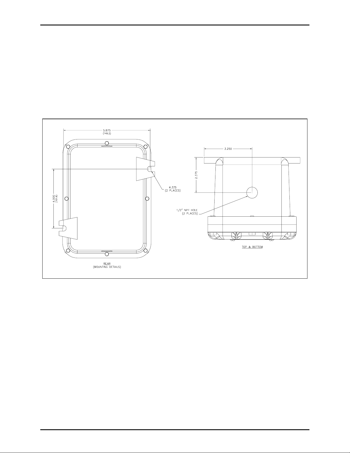
Mounting
NOTE: The mounting surface must be able to support the weight of the aluminum enclosure. See the
Specification section for the wei ght and dimen sions of t he unit.
The mounting location must be flat and provide proper clearance, rigidity and strength to support the
enclosure and all contained devices. The enclosure must be securely fastened with (customer supplied)
3/8-inch diameter steel mounting bolts and washers, or washer head bolts. Stainless steel is
recommended in corrosive environment applications.
Refer to Figure 1 for mounting dimensions.
Figure 1. Model 10438-001 Microphone I.S. Barrier Kit Mounting Details and Conduit Entries
\\s_eng\gtc proddoc s \st andard iom s - current release\42003 kit manuals \ 42003-209b.doc
06/06
Page 3
Pub. 42003-209B
M
ODEL 10438-001 INTRINSICALLY-SAFE MICROPHONE BARRIER KIT Page: 3 of 6
WARNING
Insure proper grounding to protective e art hing.
Do not disconne ct equipment whi le energized.
Inspect and clean the machined flange flame joint surfaces of both the cover and box. Surfaces must be
smooth, free of nicks, scratches, dirt or any foreign particle build-up that would prevent a proper seal.
Surfaces must seat fully against each other to provide a proper explosion-proof joint. Clean surfaces by
wiping with a clean lint-free cloth.
Make certain no cover bolts are omitted. Use only those bolts supplied with the enclosure.
N
OTE: The recommended torque setting for tightening the cover bolts is 8 ft-lbs (10.8 N-m)
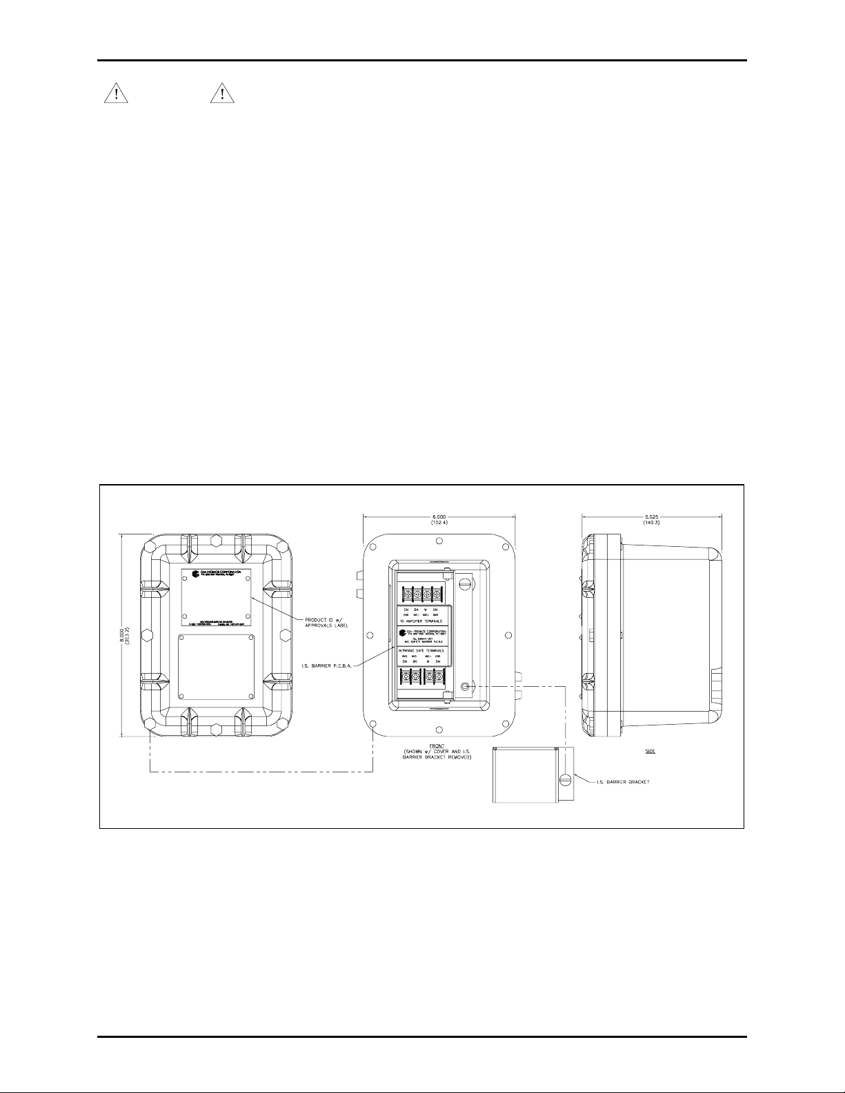
Enclosure Configuration
The Model 10438-001 I.S. barrier enclosure contains a single PCBA where all customer connections are
made. The barrier bracket covers the intrinsically-safe terminals. Remove the bracket before connecting
the I.S. wires to the PCBA. Reattach the bracket after wiring and ensure the bracket is tight against the
bott om of the enclosure. All co nnections shou ld be proper ly lugged. The enclosure itself has eight cover
mounting bolts around the perimeter. The cover of the enclosure contains all applicable approval
labeling.
Figure 2. Model 10438-001 Microphone I.S. Barrier Kit Mounting Details and Conduit Entries
\\s_eng\gtc proddoc s \st andard iom s - current release\42003 kit manuals \ 42003-209b.doc
06/06
Page 4

Pub. 42003-209B
M
ODEL 10438-001 INTRINSICALLY-SAFE MICROPHONE BARRIER KIT Page: 4 of 6
Gooseneck Microphone
The microphone is mounted to a 19-inch gooseneck and has a supplied mounting flange. The gooseneck
microphone assembly has a 25-foot cord.
Figure 3. Model 12801-001 Microphone Assembly
\\s_eng\gtc proddoc s \st andard iom s - current release\42003 kit manuals \ 42003-209b.doc
06/06
Page 5

Pub. 42003-209B
M
ODEL 10438-001 INTRINSICALLY-SAFE MICROPHONE BARRIER KIT Page: 5 of 6
Mounting the Gooseneck Microphone Assembly
Use the supplied mounting flange for mounting the gooseneck microphone assembly. A device box could
be used to mount the microphone assembly. The gooseneck should be mounted in accordance with
applicabl e el ectrical codes. R ef er t o Figure 4 for a typica l inst allation.
Figure 4. Typical Installation
\\s_eng\gtc proddoc s \st andard iom s - current release\42003 kit manuals \ 42003-209b.doc
06/06
Page 6

Pub. 42003-209B
M
ODEL 10438-001 INTRINSICALLY-SAFE MICROPHONE BARRIER KIT Page: 6 of 6
Specification s
Enclosure
Con s tru ction/ f i n ish......................................................................................... Cast al uminum/gray enamel
Mounting ...............................................................Wall or column, two 3/8-inch mounting feet with slots
Conduit entries......................................................................................................Top: one 1/2 inch NPT
Bottom: one 1/2 inch NPT
Dimensions ................................................ 8.00 H × 6.00 W × 5.52 D inches (203.2 × 152.4 × 140.3 mm)
Shipping weight ...............................................................................................................9.5 lbs. (4.3 Kg)
Temperature range (operating and storage)...........................................-4º F to +140º F (-20º C to +60º C)
Approval s
NRTL listed (USA).............................................................. Hazardous locations Class I, Div. I, Group D
when installed in accordance with GAI-Tronics Pub. 42004-381, Control Drawing # 73214
Microphone
Element:
Type ......................................................................................................... Noise-canceling, dynamic
Impedance............................................................................................................. 180 ohms, nominal
Construction/finish............................................................................................................... Steel/chrome
Connections ....................................................................................................................... Stripped wires
Dimensions ............................................................................................ 19 inches (482.6 mm) gooseneck
Supplied cable length ..................................................................................................................... 25 feet
Shipping weight ............................................................................................................ 1.25 lbs. (0.57 Kg
\\s_eng\gtc proddoc s \st andard iom s - current release\42003 kit manuals \ 42003-209b.doc
06/06
Page 7

Warranty
Equipment. GAI-Tronics warrants for a period of one (1) year from the date of shipment, that any
GAI-Tronics equipment supplied hereunder shall be free of defects in material and workmanship, shall
comply with the then-current product specifications and product literature, and if applicable, shall be fit
for the purpose specified in the agreed-upon quotation or proposal document. If (a) Seller’s goods prove
to be defective in workmanship and/or material under normal and proper usage, or unfit for the purpose
specified and agreed upon, and (b) Buyer’s claim is made within the warranty period set forth above,
Buyer may return such goods to GAI-Tronics’ nearest depot repair facility, freight prepaid, at which time
they will be repaired or replaced, at Seller’s option, without charge to Buyer. Repair or replacement shall
be Buyer’s sole and exclusive remedy. The warranty period on any repaired or replacement equipment
shall be the greater of the ninety (90) day repair warranty or one (1) year from the date the original
equipment was shipped. In no event shall GAI-Tronics warranty obligations with respect to equipment
exceed 100% of the total cost of the equipment supplied hereunder. Buyer may also be entitled to the
manufacturer’s warranty on any third-party goods supplied by GAI-Tronics hereunder. The applicability
of any such third-party warranty will be determined by GAI-Tronics.
Services. Any services GAI-Tronics provides hereunder, whether directly or through subcontractors,
shall be performed in accordance with the standard of care with which such services are normally
provided in the industry. If the services fail to meet the applicable industry standard, GAI-Tronics will
re-perform such services at no cost to buyer to correct said deficiency to Company's satisfaction provided
any and all issues are identified prior to the demobilization of the Contractor’s personnel from the work
site. Re-performance of services shall be Buyer’s sole and exclusive remedy, and in no event shall GAITronics warranty obligations with respect to services exceed 100% of the total cost of the services
provided hereunder.
Warranty Periods. Every claim by Buyer alleging a defect in the goods and/or services provided
hereunder shall be deemed waived unless such claim is made in writing within the applicable warranty
periods as set forth above. Provided, however, that if the defect complained of is latent and not
discoverable within the above warranty periods, every claim arising on account of such latent defect shall
be deemed waived unless it is made in writing within a reasonable time after such latent defect is or
should have been discovered by Buyer.
Limitations / Exclusions. The warranties herein shall not apply to, and GAI-Tronics shall not be
responsible for, any damage to the goods or failure of the services supplied hereunder, to the extent
caused by Buyer’s neglect, failure to follow operational and maintenance procedures provided with the
equipment, or the use of technicians not specifically authorized by GAI-Tronics to maintain or service the
equipment. THE WARRANTIES AND REMEDIES CONTAINED HEREIN ARE IN LIEU OF AND
EXCLUDE ALL OTHER WARRANTIES AND REMEDIES, WHETHER EXPRESS OR IMPLIED BY
OPERATION OF LAW OR OTHERWISE, INCLUDING ANY WARRANTIES OF
MERCHANTABILITY OR FITNESS FOR A PARTICULAR PURPOSE.
Return Policy
If the equipment requires service, contact your Regional Service Center for a return authorization number
(RA#). Equipment should be shipped prepaid to GAI-Tronics with a return authorization number and a
purchase order number. If the equipment is under warranty, repairs or a replacement will be made in
accordance with the warranty policy set forth above. Please include a written explanation of all defects to
assist our technicians in their troubleshooting efforts.
Call 800-492-1212 (inside the USA) or 610-777-1374 (outside the USA) for help identifying the
Regional Service Center closest to you.
(Rev. 10/06)
 Loading...