

Page 1

Pub. 42004-708L2B
GAI-TRONICS® CORPORATION
A HUBBELL COMPANY
Model 10962-001 and 10962-002
AMI Redundant Controller Modules
Confidential ity Notice
This manual is provided solely as an operational, installation, and maintenance guide and contains
sensitive business and technical information that is confidential and proprietary to GAI-Tronics.
GAI-Tronics retains all intellectual property and other rights in or to the information contained herein,
and such information may only be used in connection with the operation of your GAI-Tronics product or
system. This manual may not be disclosed in any form, in whole or in part, directly or indirectly, to any
third party.
General Information
The Model 10962-001 and 10962-002 AMI Redundant Controllers (ARC) are designed for GAI-Tronics
Page/Party
conjunction with the GAI-Tronics Model 10959-105, -106, -207, and -208 Audio Messenger Interface
(AMI) units. The AMI acts as the alarm tone/speech generator to produce emergency tones and/or prerecorded speech messages. Refer to Pub. 42004-399 for more information on the Model 10959-105 and 106 AMIs and Pub. 42004-404 for Models 10959-207 and -208 AMIs.
®
or public address systems requiring redundant alarm tone/speech generators. They work in
The ARC and AMI devices can be connected in two different configurations depending on the system
requirements. If both AMIs are to be installed at the same location, one Model 10962-002 ARC Module
can be used to control both AMIs. Refer to Figure 3. If the AMIs are to be installed at separate locations,
one Model 10960-001 ARC Module is required at each location. Each ARC will control its respective
AMI. Refer to Figure 4.
In either configuration, one AMI acts as the “active” alarm generator and the other AMI acts as the “backup.” The ARC module(s) control which AMI is active and which is back-up.
During normal alarm operation, input contacts are applied simultaneously to both the active and back-up
AMIs. The ARC module(s) allow only the active generator to play the tone/speech message over the
system speakers. The back-up AMI is held in standby mode to prevent audio mixing of the two AMI
tone/speech messages.
In the event of a failure of the active AMI, the back-up AMI becomes active and plays its tone/speech
message over the system speakers.
GAI-Tronics Corporation 400 E. Wyomissing Ave. Mohnton, PA 19540 USA
610-777-1374 800-492-1212 Fax: 610-796-5954
V
ISIT WWW.GAI-TRONICS.COM FOR PRODUCT LITERATURE AND MANUALS
Page 2

Pub. 42004-708L2B
Model 10962-001 and 10962-002 AMI Redundant Controller Modules Page: 2 of 17
Hardware Configuration
The Model 10962-001 Single Redundant Controller Module consists of one AMI Redundancy Controller
PCBA mounted to the base and one LCD module mounted to the front of the base. Model 10962-002
Dual Redundant Controller has two 69842-001 AMI Redundancy Controller PCBAs mounted to the base
and has two LCD modules mounted to the front of the base.
Figure 1. Model 10962-001 Single Redundant Controller for one AMI
Designed for installations where the active and back-up AMIs are installed at separate locations
Figure 2. Model 10962-002 Redundant Controller Module
Designed for installations where the active and back-up AMIs are installed at the same location
f:\standard ioms - current release\42004 instr. manuals\42004-708l2b.doc
06/10
Page 3

Pub. 42004-708L2B
Model 10962-001 and 10962-002 AMI Redundant Controller Modules Page: 3 of 17
Block Diagrams
Figure 3 shows the equipment block diagram when the ARC module and AMIs are installed in the same
location.
Figure 3. Model 10962-002 ARC and AMI Block Diagram
f:\standard ioms - current release\42004 instr. manuals\42004-708l2b.doc
06/10
Page 4
Pub. 42004-708L2B
Model 10962-001 and 10962-002 AMI Redundant Controller Modules Page: 4 of 17
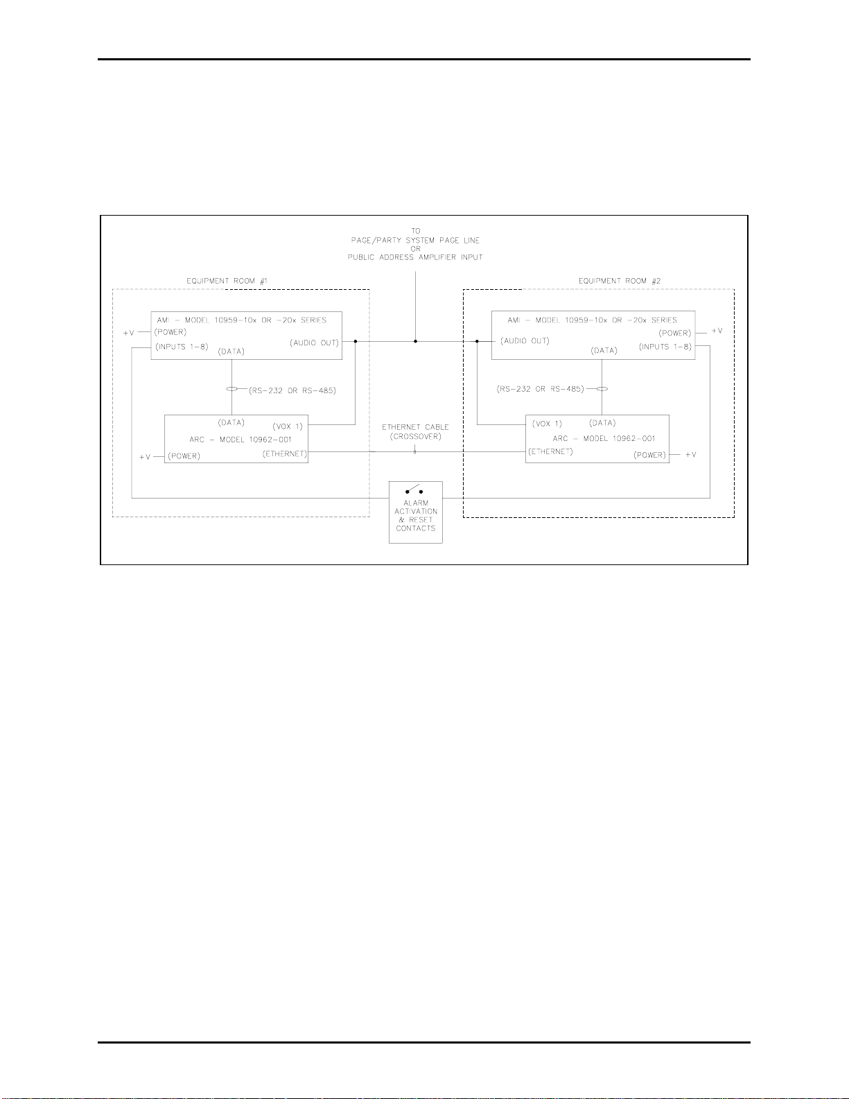
Figure 4 shows the equipment block diagram when the ARC modules and AMIs are installed in two
different locations.
OTE: When using a CAT 5 cable to directly connect the two ARC modules (as illustrated), the
N
maximum distance between ARC devices is 100 meters. The distance can be extended by using any
external Ethernet devices such as fiber optic modems, hubs, etc.
Figure 4. Model 10962-001 ARC and AMI Block Diagram
f:\standard ioms - current release\42004 instr. manuals\42004-708l2b.doc
06/10
Page 5
Pub. 42004-708L2B
Model 10962-001 and 10962-002 AMI Redundant Controller Modules Page: 5 of 17
Installation
Mounting
The Model 10962-001 and -002 Redundant Controller Modules can be mounted in a standard EIA 19inch electronic equipment rack. Each model requires 1U (1.75 inches) of rack space. Complete the
following steps for mounting in the rack:
1. Attach the mounting brackets with the eight 8-32 × 3/8-inch screws provided.
2. Mount the AMI Redundant Controller into the rack using four 10-32 × ¾-inch screws with plastic
shoulder washers.
Wiring Terminations
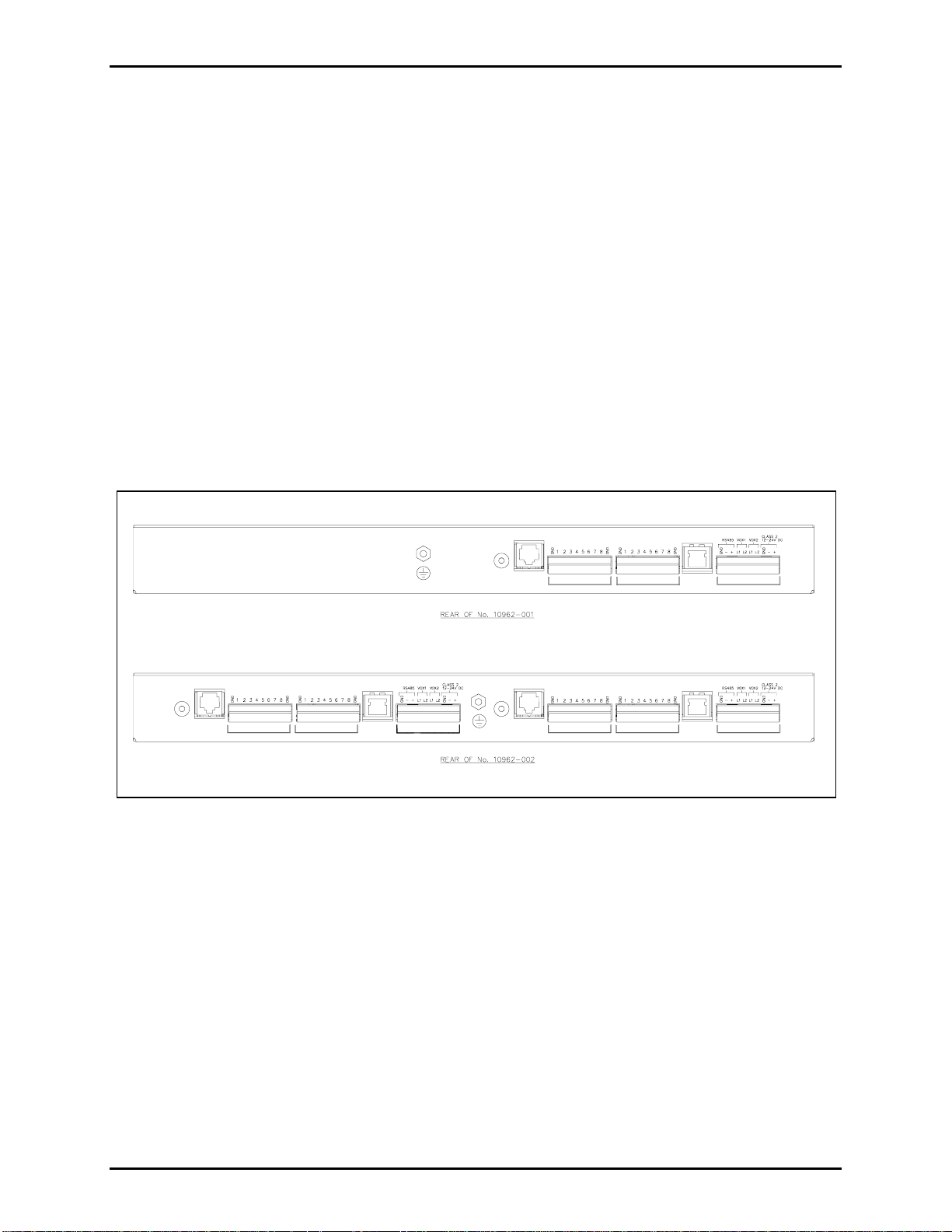
The Model 10962-001 AMI Redundant Controller provides three terminal blocks, an RJ11 receptacle
labeled RS-232,
The Model 10962-002 is equipped with two sets of terminal blocks and receptacles since it has two
PCBAs. Refer to Figure 5 below for terminal locations.
and an RJ45 receptacle labeled ETHERNET on the rear panel for wiring connections.
ADDR
RS232
LOGIC OUTPUTS
LOGIC INP UTS
ETHERNET
RS232
ADDR
LOGIC OUTPUTS LOGIC INPUTS SYSTEM
RS232
ADDR
SYSTEM
ETHERNET
ETHERNET
SYSTEMLOGIC INPUTSLOGIC OUTPUTS
Figure 5. Redundant Controllers - Rear Panels
f:\standard ioms - current release\42004 instr. manuals\42004-708l2b.doc
06/10
Page 6
Pub. 42004-708L2B
Model 10962-001 and 10962-002 AMI Redundant Controller Modules Page: 6 of 17
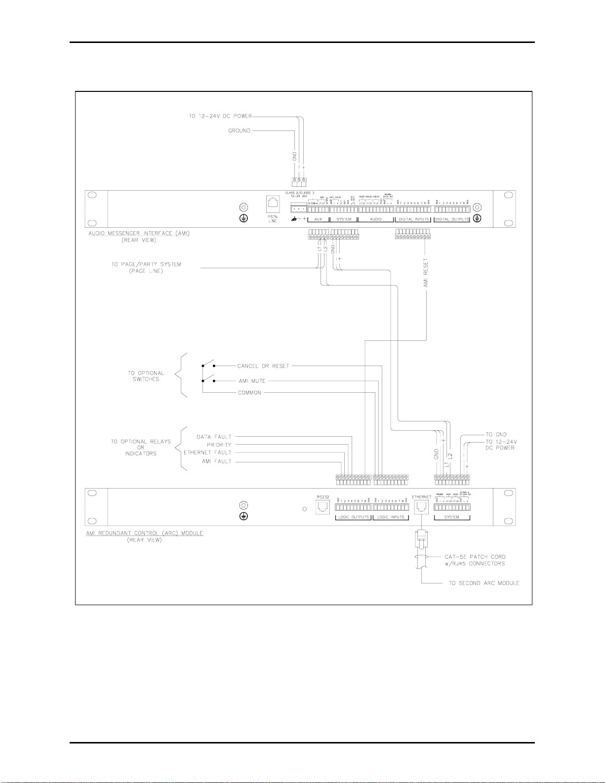
Refer to Figure 6 for a typical connection diagram between the ARC and the AMI.
Figure 6. ARC and the 100 Series AMI Connection Diagram
f:\standard ioms - current release\42004 instr. manuals\42004-708l2b.doc
06/10
Page 7

Pub. 42004-708L2B
Model 10962-001 and 10962-002 AMI Redundant Controller Modules Page: 7 of 17
Figure 7. ARC and the 200 Series AMI Connection Diagram
f:\standard ioms - current release\42004 instr. manuals\42004-708l2b.doc
06/10
Page 8

Pub. 42004-708L2B
Model 10962-001 and 10962-002 AMI Redundant Controller Modules Page: 8 of 17
System Terminals
The system terminals are used for data, audio and power connections as follows:
RS-485
VOX
1
VOX
2
12-24V
DC
The RS-485 terminals are for a serial data connection to the AMI. This RS-485 data line
allows the ARC to monitor the operating status of the AMI and control the playing of the
AMI alarm tones and messages.
Connect the RS-485 +, –, and GND terminals to the E
XT DATA terminals on the AMI.
Observe (–) and (+) polarity when connecting the data line. Refer to Figure 6.
OTE: When using the RS-485 data connection, the RS-232 cannot be used and vise
N
versa.
The VOX 1 terminals are for sampling the audio output of the AMI. When the AMI is
playing a message, these terminals verify that audio is actually being generated from the
AMI. Connect the VOX 1 terminals to either the 600-ohm or 33-ohm audio output of the
AMI using a twisted pair cable. Refer to Figure 6. (33-ohm audio is shown.)
The VOX 2 terminals are reserved for future use. Do not make any wiring connections to
these terminals.
The 12–24 V dc terminals are used to connect power to the unit. As labeled, the ARC can
operate from 12 to 24 V dc. Power the AMI from the same voltage as the ARC. Observe
(–) and (+) polarity when connecting the power. Connect the GND terminal to earth
ground. Refer to Figure 6.
f:\standard ioms - current release\42004 instr. manuals\42004-708l2b.doc
06/10
Page 9

Pub. 42004-708L2B
Model 10962-001 and 10962-002 AMI Redundant Controller Modules Page: 9 of 17
Logic Output Terminals
The logic outputs are open collector type designed to drive externally-mounted relays or other indicating
circuits. Each output can sink up to 100 mA of current when active. External circuitry (relays, indicators,
etc.) must be powered from an external power supply of the same voltage used to power the ARC module
(12 to 24 V dc). The ground (or dc common) terminals of the external power supply must be tied to either
of the GND terminals of the ARC. The following table outlines each output’s active state:
Output Function Notes
1 AMI Fault This output will become active when the ARC receives an error message
from the AMI; or
when the ARC no longer detects audio on the AMI
output during the playing of an alarm message or page.
2 Ethernet Fault This output becomes active when the Ethernet/Network connection is
broken between the ARC modules and they can no longer communicate
with each other.
3 Priority Under normal operation, this output is active only on the ARC module
that is controlling the alarm play.
If the Ethernet connection is broken between ARCs, this output will be
active on both units.
4 Data Fault This output is active when the ARC loses data communication with the
AMI. This can indicate a problem with the RS-232 or RS-485 cable
connection.
5 Spare Reserved for future use.
6 Spare Reserved for future use.
7 Spare Reserved for future use.
8 Data Fault
During Message
This output is active when the ARC loses data communication with the
AMI while the AMI is playing a message.
In this case, the output should be used as a “reset” input to the AMI. This
resolves the issue where RS-232 or RS-485 communication is lost, and the
ARC has no means to command the AMI to stop playing a message or
page.
f:\standard ioms - current release\42004 instr. manuals\42004-708l2b.doc
06/10
Page 10

Pub. 42004-708L2B
Model 10962-001 and 10962-002 AMI Redundant Controller Modules Page: 10 of 17
Logic Input Terminals
The logic inputs are designed to accept a normally open contact closure to stop the AMI from playing a
message during an active alarm or page. The input switch contact must connect the GND terminal to the
corresponding input terminal to activate. The following table outlines each input function:
Input Function Notes
1 AMI mute While this input is active (switch is closed), the audio output of the AMI is
muted or silenced.
The input is non-latching, which means the mute is only active while the input
switch is closed.
2
AMI message
silence
or
AMI message
reset
This input is programmable using the ARC’s embedded web page
configurator. It can be programmed as either a Silence input or Reset input.
Silence input:
If the AMI is playing a message, and has one or more messages in queue, and
a Silence input contact is detected, the currently playing message is reset
(stopped) and the next message in the queue is played.
Reset input:
When a Reset input contact is detected, the currently playing message and any
messages in queue are reset (stopped).
The Silence and Reset input are latching, which means the input switch
should be momentary type contact.
The factory default setting is SILENCE.
3 Spare Reserved for future use
4 Spare Reserved for future use
5 Spare Reserved for future use
6 Spare Reserved for future use
7 Spare Reserved for future use
8 Spare Reserved for future use
Ethernet Receptacle
A 100 Mb Ethernet connection is required between the two ARC Modules using the RJ45 receptacle. Use
a cross-over CAT 5 cable between the two ARC modules if connecting them directly. If an Ethernet hub
is used, connect each ARC module to the Ethernet hub using a straight pinned CAT 5 cable.
f:\standard ioms - current release\42004 instr. manuals\42004-708l2b.doc
06/10
Page 11

Pub. 42004-708L2B
Model 10962-001 and 10962-002 AMI Redundant Controller Modules Page: 11 of 17
RS-232 Receptacle
The RS-232 connector is for a serial data connection to the AMI. This data line allows the ARC to
monitor the operating status of the AMI and also to control playing of the AMI messages. The RS-232
data line is DISABLED as the factory default. Prior to using this connection, it must be enabled using the
ARC’s embedded web page configuration screen. An RJ11 type modular cab le is connec ted between thi s
connector and the accessory jack on the AMI front panel. Cable pin-out is as follows:
N
OTE 1: When using the RS-485 data connection, the RS-232 cannot be used and vise versa.
OTE 2: If the ARC and the AMI are not powered from the same source, a GND connection must be
N
made between them for the RS-232 communication to work properly. Connect the GND connection on
the Logic Inputs terminal block on the ARC to the GND connection on the Digital Inputs terminal block
on the AMI.
ARC
Pin No. Function
AMI
Pin No. Notes:
1 Spare 1
2 Data TX (to AMI) 7
3 PTT 6 Used only when paging microphone is required for
AMI.
4 Mic HI 4 Used only when paging microphone is required for
AMI.
5 Mic Lo 5 Used only when paging microphone is required for
AMI.
6 Spare
7 Data RX (from AMI) 2
8 Spare
ADDR Hex Switch
The hex switch labeled ADDR is used to set the operating mode of the ARC on initial power-up. Each
time the ADDR switch is changed, the unit must be restarted for the new setting to be recognized. Reset
the ARC by momentarily removing power.
When the ADDR switch is set to “0” the ARC is the “primary” controller meaning that in normal
operation, the AMI connected to it will be the “ACTIVE” alarm generator.
When the ADDR switch is set to “1” the ARC is the “secondary” controller meaning that in normal
operation, the AMI connected to it will be the “BACK-UP” alarm generator.
All other ADDR settings (2–F) are invalid for normal operating mode and should not be selected.
f:\standard ioms - current release\42004 instr. manuals\42004-708l2b.doc
06/10
Page 12

Pub. 42004-708L2B
Model 10962-001 and 10962-002 AMI Redundant Controller Modules Page: 12 of 17
Operation
LCD Display
A two-line LCD display is mounted on the front of the ARC to indicate operational status of the ARC
and AMI.
The first line of the display is a text message indicating various AMI operations as follows:
Message Meaning
AMI:RESPONDING
AMI:NO RESPONSE
AMI:PLAYING
AMI:MUTED
AMI:FAILED
AMI:NOT READY
AMI:MEDIA ERR
AMI:AUDIO ERR
AMI:RS485 ERR
AMI responded with IDLE status following a status request from the ARC.
The AMI has not responded to the status request from the ARC for 5 seconds.
AMI is currently playing a message or page.
The AMI’s audio output is muted, but the AMI is playing a message or a
telephone page.
The AMI has denied a request from the ARC; or the AMI has returned an
unrecognizable response.
The AMI has returned a “Not Ready” response to a status request from the ARC.
The AMI has returned a fault to the ARC, indicating that the Compact Flash
memory card has been removed.
The AMI has returned a fault to the ARC, indicating the AMI cannot detect
audio at its internal monitoring circuit.
The AMI has returned a fault to the ARC, indicating an RS-485 communications
failure with one or more modules.
AMI:DSP ERR
The AMI has returned a fault to the ARC, indicating communications with its
internal digital signal processor (DSP) has stopped.
f:\standard ioms - current release\42004 instr. manuals\42004-708l2b.doc
06/10
Page 13

Pub. 42004-708L2B
Model 10962-001 and 10962-002 AMI Redundant Controller Modules Page: 13 of 17
LCD Visual Indicators
The second line of the LCD display indicates if the ARC is set as the primary or secondary controller. It
also displays various characte rs to in dicat e opera tio ns as fo llows:
Icon Meaning
¥
This icon indicates the active ARC/AMI.
The speaker symbol appears when the AMI is playing a message or a telephone page.
The speaker icon turns solid when the AMI is playing a message or page but the output is
muted by the ARC mute input.
↕
←
→
This symbol indicates a working Ethernet connection between the two ARC modules.
Absence of the icon indicates an Ethernet problem.
This symbol indicates that messages are being sent to the AMI from the ARC via the RS-232
or RS-485 connection. This symbol should flash when messages are being actively sent to the
AMI and expected responses are being received from the AMI. If the ARC stops sending
messages to the AMI, this symbol will no longer flash.
This symbol indicates that messages are being sent to the ARC from the AMI via the RS-232
or RS-485 connection. This symbol should flash when recognized messages are received from
the AMI. If the ARC stops receiving recognized messages from the AMI, this symbol will not
be displayed.
f:\standard ioms - current release\42004 instr. manuals\42004-708l2b.doc
06/10
Page 14

Pub. 42004-708L2B
Model 10962-001 and 10962-002 AMI Redundant Controller Modules Page: 14 of 17
Maintenance
ARC Diagnostics
There are two board level diagnostic tests available that are enabled by setting the ADDR switch. The
top cover must be removed from the ARC module to allow the test LEDs to be observed.
VOX Input Test
When ADDR switch is set to “A,” followed by a board reset, the LCD will show DIAG: VOX INPUT.
This indicates that the ARC board is in diagnostic mode for the VOX1 and VOX2 inputs.
When audio is detected on VOX1, LED 3 on the PCBA illuminates. LED 3 turns off when audio is no
longer detected at the VOX1 input. Likewise, when audio is detected on VOX2 input, LED 4
illuminates. LED 4 turns off when audio is no longer detected at the VOX2 input.
Input/Output (Switch B)
When ADDR switch is set to “B,” followed by a board reset, the LCD will show DIAG: I/O. This
indicates that the ARC board is in the diagnostic mode for testing the inputs and outputs.
When Input 1 is activated, Output 1 will be activated. When Input 2 is activated, Output 2 will be
activated, etc. This sequence is true for Input 1 through Input 8.
f:\standard ioms - current release\42004 instr. manuals\42004-708l2b.doc
06/10
Page 15

Pub. 42004-708L2B
Model 10962-001 and 10962-002 AMI Redundant Controller Modules Page: 15 of 17
ARC Embedded Web Page
The ARC contains an embedded web server, which can be used for altering some of the unit’s factory
default settings. The IP address of the unit depends on the setting of the ADDR switch.
• When the ADDR switch is set to “0” the ARC is the Primary controller and the IP address is
192.168.1.151
• When the ADDR switch is set to “1” the ARC is the Secondary controller and the IP address is
192.168.1.152
Connect a computer to the Ethernet plug of the ARC using a crossover CAT5 network cable. Using
Internet Explorer open the ARC webpage by typing in the correct IP address listed above. The following
screen display is an example of the web page for the Primary Controller.
f:\standard ioms - current release\42004 instr. manuals\42004-708l2b.doc
06/10
Page 16

Pub. 42004-708L2B
Model 10962-001 and 10962-002 AMI Redundant Controller Modules Page: 16 of 17
The following functions may be changed using the web-page.
Function Meaning
Alarm Button
Mode
AMI
Communication
Audio Dropout
Time
Audio Detect
Threshold
These radio buttons select the mode assigned to Input 2.
Selecting Silence mode will cause the AMI to stop playing its current message or
page when the button is pressed.
Reset mode will cause the AMI to clear all of its alarms and pages when the button
is pressed.
This button is used to select the communication interface between the ARC Board
and the AMI (RS-232 or RS-485). RS-485 is the default communication interface.
After changing this value, the ARC board MUST be reset. The web page must be
refreshed following the board reset.
Assuming no audio is detected at the VOX 1 input, this setting value determines the
length of time (in seconds) before the ARC reports a “No Audio” condition and
switches control to the back-up AMI. The range is 5–10 seconds in 1-second
increments. The default value is 5 seconds. This parameter may need to be altered
if there are pause (silence) times in the AMI message greater than 5 seconds.
This setting specifies the threshold level at which the audio is detected by the ARC
board. Selecting the Disable option from the drop-down list will disable audio
detection. Valid values for audio detection are 1 through 10, ranging from 100 mV
to 1 V, in steps of 100 mV. The default value of this parameter is 3 (300 mV).
Set AMI Date or
Time
ARC Controller
Configuration
Allows the user to change the date and time on the corresponding AMI. N
OTE:
This is the only way to set the date/time on the AMI, and must be done separately
for each ARC board. The default web page values for date and time are set
according to the last date/time retrieved from the AMI. The data connection to the
AMI must be functioning properly to allow the date and time to be set.
Displays the network configuration data for the ARC board:
• Current MAC address
• Current IP address
• Subnet mask
• Gateway address
These values cannot be modified via the web page.
f:\standard ioms - current release\42004 instr. manuals\42004-708l2b.doc
06/10
Page 17

Pub. 42004-708L2B
Model 10962-001 and 10962-002 AMI Redundant Controller Modules Page: 17 of 17
AMI Configuration Requirements
The following parameters must set:
• The Advance Control must be enabled on the Global parameter tab.
• Input 8 must be Maintained - Normally Open switch type, and the Clear All function must be
selected. This AMI Input 8 should be wired to Output 8 on the ARC. This input causes the ARC to
reset the AMI message in the event that data communication is lost while an alarm is active.
All other settings regarding the AMI configuration can be project specific.
Specification s
Power Supply Requirements
Connection to a 12 to 24 V dc (UL-listed) Class 2 power source................................... 0.2 amps minimum
Power consumed................................................................................................................ 2 watts maximum
Electrical
Logic outputs ..................................Sink 100 mA per output to circuit common and must be powered from
an external power supply of the same voltage as the ARC module
Mechanical
Enclosure ................................................................... Steel body and cover, black fine-textured paint finish
Mounting..................................................................................................Rack-mount, IU Standard, 19-inch
Dimensions .............................................19.00 W × 5.30 D × 1.75 H inches (431 × 135 × 44 mm) nominal
Weight................................................................................................................................................... 5 lbs.
Environmental
Temperature range...................................................................................+32º F to +122º F (0º C to +50º C)
f:\standard ioms - current release\42004 instr. manuals\42004-708l2b.doc
06/10
Page 18

Warranty
Equipment. GAI-Tronics warrants for a period of one (1) year from the date of shipment, that any
GAI-Tronics equipment supplied hereunder shall be free of defects in material and workmanship, shall
comply with the then-current product specifications and product literature, and if applicable, shall be fit
for the purpose specified in the agreed-upon quotation or proposal document. If (a) Seller’s goods prove
to be defective in workmanship and/or material under normal and proper usage, or unfit for the purpose
specified and agreed upon, and (b) Buyer’s claim is made within the warranty period set forth above,
Buyer may return such goods to GAI-Tronics’ nearest depot repair facility, freight prepaid, at which time
they will be repaired or replaced, at Seller’s option, without charge to Buyer. Repair or replacement shall
be Buyer’s sole and exclusive remedy. The warranty period on any repaired or replacement equipment
shall be the greater of the ninety (90) day repair warranty or one (1) year from the date the original
equipment was shipped. In no event shall GAI-Tronics warranty obligations with respect to equipment
exceed 100% of the total cost of the equipment supplied hereunder. Buyer may also be entitled to the
manufacturer’s warranty on any third-party goods supplied by GAI-Tronics hereunder. The applicability
of any such third-party warranty will be determined by GAI-Tronics.
Services. Any services GAI-Tronics provides hereunder, whether directly or through subcontractors,
shall be performed in accordance with the standard of care with which such services are normally
provided in the industry. If the services fail to meet the applicable industry standard, GAI-Tronics will
re-perform such services at no cost to buyer to correct said deficiency to Company's satisfaction provided
any and all issues are identified prior to the demobilization of the Contractor’s personnel from the work
site. Re-performance of services shall be Buyer’s sole and exclusive remedy, and in no event shall GAITronics warranty obligations with respect to services exceed 100% of the total cost of the services
provided hereunder.
Warranty Periods. Every claim by Buyer alleging a defect in the goods and/or services provided
hereunder shall be deemed waived unless such claim is made in writing within the applicable warranty
periods as set forth above. Provided, however, that if the defect complained of is latent and not
discoverable within the above warranty periods, every claim arising on account of such latent defect shall
be deemed waived unless it is made in writing within a reasonable time after such latent defect is or
should have been discovered by Buyer.
Limitations / Exclusions. The warranties herein shall not apply to, and GAI-Tronics shall not be
responsible for, any damage to the goods or failure of the services supplied hereunder, to the extent
caused by Buyer’s neglect, failure to follow operational and maintenance procedures provided with the
equipment, or the use of technicians not specifically authorized by GAI-Tronics to maintain or service the
equipment. THE WARRANTIES AND REMEDIES CONTAINED HEREIN ARE IN LIEU OF AND
EXCLUDE ALL OTHER WARRANTIES AND REMEDIES, WHETHER EXPRESS OR IMPLIED BY
OPERATION OF LAW OR OTHERWISE, INCLUDING ANY WARRANTIES OF
MERCHANTABILITY OR FITNESS FOR A PARTICULAR PURPOSE.
Return Policy
If the equipment requires service, contact your Regional Service Center for a return authorization number
(RA#). Equipment should be shipped prepaid to GAI-Tronics with a return authorization number and a
purchase order number. If the equipment is under warranty, repairs or a replacement will be made in
accordance with the warranty policy set forth above. Please include a written explanation of all defects to
assist our technicians in their troubleshooting efforts.
Call 800-492-1212 (inside the USA) or 610-777-1374 (outside the USA) for help identifying the
Regional Service Center closest to you.
(Rev. 10/06)
 Loading...