

Page 1

Pub. 42004-371B
GAI-TRONICS® CORPORATION
A HUBBELL COMPANY
Model 10961-001
AMI Centra-Page Interface
Confidentiality Notice
This manua l is provide d sole ly as an operatio nal, installation, and ma inte nance guide and conta ins
sensitive business and t e chnical informatio n tha t is confidentia l and pr opri et ary to GAI- Tronics. GAITronics retains all intellectual property and other rights in or to the information contained herein, and
such information may on ly be u sed in conn e ction with the operatio n of you r GAI-Tr onics p rodu c t or
system. This manu al may not be dis clos e d in any form, in whole or in pa rt, direct ly or i ndir ectly, to a ny
third pa r ty.
General Information
GAI-Tronics’ Centra-Page systems provide dependable paging and party line communications for rugged
and haza rdous indust ria l f aciliti es . Cent ra- Page syste ms feature centrally loc ated elect ron ic s tha t pr ovide
environ me nta l prot e c tion and u nitiz e d amp l ificatio n for easy ma inte nance. Standard Cent ra- Page
cabinets can support up to 30 handset stations, and in most cases, up to 60 paging speakers. Alarms and
telephone interfacing can be added to Centra-Page systems with the addition of a Model 10959-006
Audio Messenger Interface (AMI) and a Model 10961-001 AMI Centra-Page Interface.
The Model 10961-001 AMI Centra-Page Interface, in combination with the AMI, can replace the Model
H97019 Programmable Tone/Speech Generator and the Model 10448-202 Telephone Interface for
Centra-Page systems or the Model B93017 Programmable Telephone Interface in CP/P II systems.
The Model 10961-001 AMI Centra-Page Interface is designed to provide five alarm inputs to activate the
Model 10959-006 AMI’s tone/speech generator when both are mounted in a Model 10468-002 CentraPa ge C entr al Cabinet and are pr operly configured.
The AMI Centra-Page Interface can provide Centra-Page systems access to the public telephone network.
The telephone line coupler is designed for loop start operation with bridged ringing. This coupler is
registered by the FCC number ADGOT01B46055. The Ringer Equivalence Number (REN) is 0.1A, with
an RJ11C connection.
GAI-Tronics Corporation P.O. Box 1060, Readi ng, PA 19607-1060 USA
610-777-1374 800-492-1212 Fax: 610-796-5954
ISIT WWW.GAI-TRONICS.COM FOR PRODUCT LITERATURE AND MANUALS
V
Page 2
Pub. 42004-371B
Model 10961-001 AMI Cent r a- P age Interface Page: 2 of 22
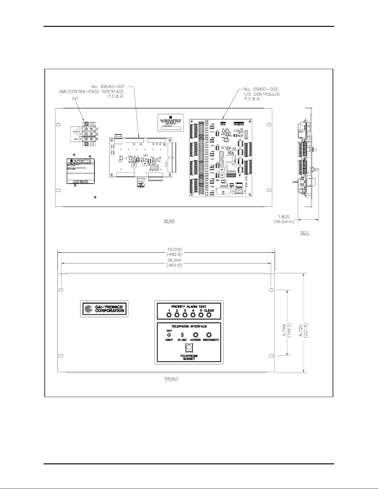
The Model 10961-001 AMI Centra-Page Interface contains a priority alarm test panel and a telephone
interface panel. The 69542-001 PCBA and 69407-002 I/O Controller PCBA are mounted on the rear
along with a power terminal block. The AMI Centra-Page Interface outline is shown in Figure 1.
Figure 1. Model 10961-001 AMI Centra-Page Interface
\\s_eng\gtc proddoc s \st andard iom s - current release\42004 instr. manuals \ 42004-371b. doc
09/05
Page 3
Pub. 42004-371B
Model 10961-001 AMI Cent r a- P age Interface Page: 3 of 22
Installation
Power Disconnect. The power cord is the main power disconnect for all un its.
Disjontion de l’alimentation. Le cordon d’alimentation est la disjonction d’alimentation principale tous les appareils.
Para Desconectar la Alimentación: El cable de alimentación es el medio principal de desconexión del equipo.
Netzanschluß. Wenn man das Netzkabel aus der Steckdose zieht, dann ist die Spannungszuführung zum Gerät vollkommen
unterbrochen.
CAUTION To reduce the risk of fire, use only No. 26 AWG or larger telecommunicat ion line cord.
ATTENTION Pour réduire le risque d’incendie, utiliser uniquement des conducteurs de télécommunications 26 AWG ou
de section sup érieure.
PRECAUCIÓN Para aminorar la posibilidad de in cendios, utili ce s olam ente cable de telecomun icaciones de calibre 26
(sistema AWG americano) o mayor.
VORSICHT Um die Brandgefahr zu verrin gern, verwenden Sie bit te nur Fernmeldekabel der Stärke Nr. 26 AWG oder
höher.
WARNING
WARNING
Do not apply power until all the connections have been wired.
Connect only to a UL-listed Class 2 power source.
If replacing existing equipment, remove the tone generator, telephone interface, and the associated wiring
prior to installing the Model 10961-001 Interface.
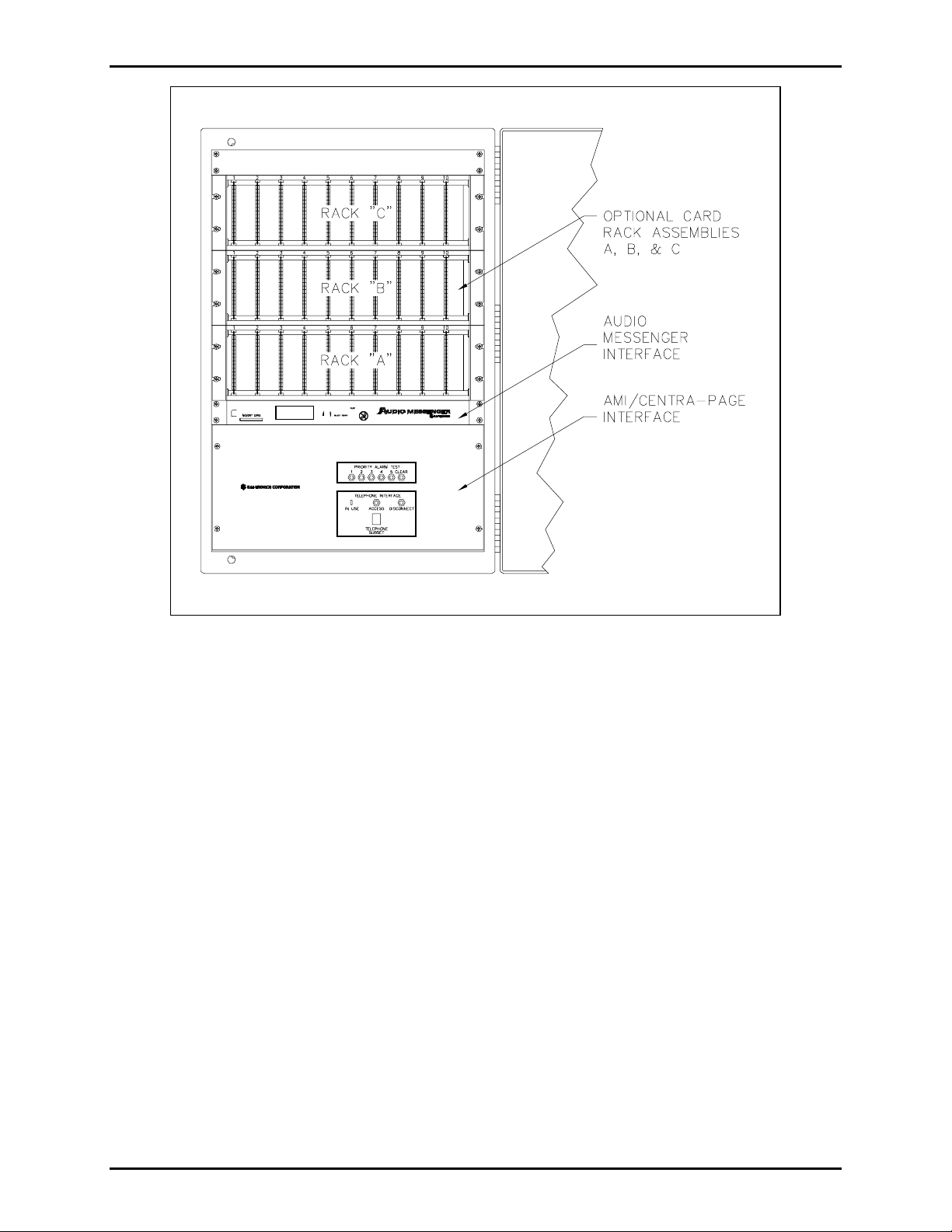
The Model 10961-001 AMI Centra-Page Interface and the Model 10959-006 AMI should be installed in
the Centra-Page central cabinet at the same time. Allow 6U of open space immediately below the Model
10461-002 Card Rack in the lowest position in the cabinet to mount the AMI, and immediately beneath it,
the Centra-Page Interface. Refer to Figure 2.
OTE: The standard lengths of the interconnecting cables do not allow for blank panel space between
N
th ese p ieces of eq uipme nt.
1. Carefully unpack and identify the various components. The Model 10959-006 AMI includes a parts
envelope containing mounting hardware, a CD, and a 12 V dc Walpac. The Model 10961-001 AMI
Centra-Page Interface includes a parts envelope containing seven cable assemblies, four mounting
screws, a SmartMedia
®
card, a modu lar RJ11 s plitter, an d a Centra- P age terminal block label. The
seven cable assemblies are:
• 61531-033 • 61531-038 • 61531-041 (9-inch green ground wire)
• 61531-034 • 61531-039
• 61531-035 • 61531-040
2. Use the mounting hardware supplied with the AMI to mount it directly below the bottom card rack.
The AMI occupies 1U of space.
3. Make all the required wiring connections before mounting the Model 10961-001 AMI Centra-Page
Interface. Refer to Figure 4 and Figure 5.
\\s_eng\gtc proddoc s \st andard iom s - current release\42004 instr. manuals \ 42004-371b. doc
09/05
Page 4
Pub. 42004-371B
Model 10961-001 AMI Cent r a- P age Interface Page: 4 of 22
Figure 2. Centra- Page C entr al Ca binet with AMI a nd AMI C entr a-P age Interf ace
(fr ont of center section)
\\s_eng\gtc proddoc s \st andard iom s - current release\42004 instr. manuals \ 42004-371b. doc
09/05
Page 5
Pub. 42004-371B
Model 10961-001 AMI Cent r a- P age Interface Page: 5 of 22
Figure 3. Centr a-P age Cent ral Cabin et
(Showing front of rear section and the rear of the center section)
\\s_eng\gtc proddoc s \st andard iom s - current release\42004 instr. manuals \ 42004-371b. doc
09/05
Page 6

Pub. 42004-371B
Model 10961-001 AMI Cent r a- P age Interface Page: 6 of 22
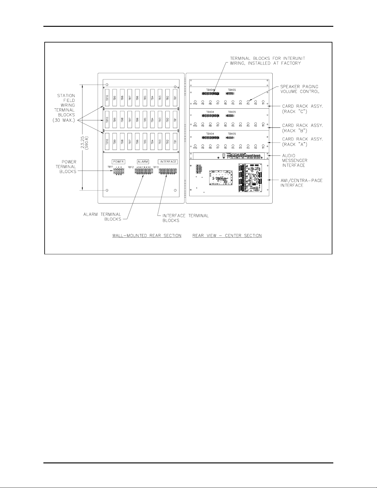
Figure 4. Wiring of Central Cabinet’s the wall-mounted section
\\s_eng\gtc proddoc s \st andard iom s - current release\42004 instr. manuals \ 42004-371b. doc
09/05
Page 7
Pub. 42004-371B
Model 10961-001 AMI Cent r a- P age Interface Page: 7 of 22
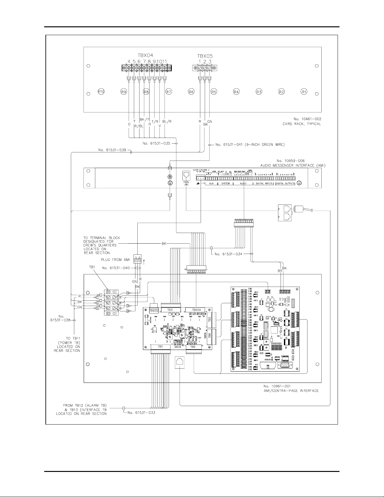
Figure 5. Wirin g of th e rear of th e C entr al Cabinet ’ s center sect ion
\\s_eng\gtc proddoc s \st andard iom s - current release\42004 instr. manuals \ 42004-371b. doc
09/05
Page 8

Pub. 42004-371B
Model 10961-001 AMI Cent r a- P age Interface Page: 8 of 22
NOTE: The connectors for TB6 (power) and TB3 (audio) from the back of the AMI must be attached
(terminated) to the cable assemblies according to the steps 4 and 5 below:
4. Remove TB3 (AUDIO) conne c tor from the back of the AM I . Attach the ma tin g end of the conne c tor
to the 61531-034 cable assembly. See Figure 6. Using this 10-position removable terminal block,
connect the six wires from positions 1 through 6 of the 61531-034 cable assembly. The brown and
black wires from positions 9 and 10 are not connected to this terminal block. Refer to Figure 5.
Figure 6. 61531-034 Cable Assembly
Connector from AMI TB3 (Audio)
Terminal Wire Color Function
TB3-1 Purple + Page or alarm from AMI
TB3-2 Blue - Page or alarm from AMI
TB3-3 Red + Party line from AMI
TB3-4 Green - Party line from AMI
TB3-5 Yellow + Party line to AMI
TB3-6 Orange - Party line to AMI
TB3-7 thru N/C
TB3-10
\\s_eng\gtc proddoc s \st andard iom s - current release\42004 instr. manuals \ 42004-371b. doc
09/05
Page 9

Pub. 42004-371B
Model 10961-001 AMI Cent r a- P age Interface Page: 9 of 22
5. Remove TB6 (power) connector plug from its socket on the back of the AMI. Attach the TB6
connector plug to the 61531-040 cable assembly conductor ends that do not have spade lugs. Refer to
Figure 7.
Figure 7. 61531-040 Cable Assembly Connector Termination
6. Connect the 61531-038 and 61531-039 cable assemblies to the outside of TB1 (mounted on the AMI
Centra-Page Interface plate) and the 61531-040 cable assembly to the inside of TB1.
TB1 on AMI Centra-Page Interface Panel
Terminal Wire Color Function
TB1-1 R ed +24 V dc
TB1-2 Black (-) of 24 V dc
TB1-3 Green Ground
7. Connect the 61531-033 cable connector to TB1 on the 69542-001 PCBA.
8. Connect the 61531-034 cable connector (the end without the brown and black wires) to TB3 on the
69542-001 PCBA. Connect the brown and black wires to TB2 on the 69407-002 PCBA.
TB2 on 69542-001
Terminal Wire Color Function
TB2-1 Brown +RS485 data
TB2-2 Black -RS485 data
9. Connect the 61531-035 cable connector to TBX04 on the 69542-001 PCBA.
\\s_eng\gtc proddoc s \st andard iom s - current release\42004 instr. manuals \ 42004-371b. doc
09/05
Page 10

Pub. 42004-371B
Model 10961-001 AMI Cent r a- P age Interface Page: 10 of 22
10. Mount the Model 10961-001 Interface directly beneath the AMI in the Centra-Page central cabinet.
11. Connect the 61531-038 cable assembly to the central cabinet’s TB11 located on the rear panel. See
Figure 4.
Centra-Page Cabinet Back Panel - Power -TB11
Terminal Wire Color Function
TB11-1 Red +24 V dc
TB11-2 Blac k (-) of 24 V dc
TB11-3 Green Ground
11. Connect the red and black wires of cable assembly 61531-039 to the TBX05 terminal block on the
card rack located in the lowest mounting position. Connect the green wire from the 61531-039 cable
assembly and one end of the 61531-041 grounding wire to the grounding lug on the back of the AMI.
Connect the other end of the 61531-041 to the card rack’s TBX05 terminal block.
Figure 8. 61531-039 Cable Assembly Termination
\\s_eng\gtc proddoc s \st andard iom s - current release\42004 instr. manuals \ 42004-371b. doc
09/05
Page 11

Pub. 42004-371B
Model 10961-001 AMI Cent r a- P age Interface Page: 11 of 22
12. Plug the 61531-040 cable’s TB6 connector (attached in step 5) back into its original location on the
rear of the AMI.
13. Ins tal l the Centra-Page ter m inal block label beneath T B13 on the central c abin et’s rear panel.
Connect the 61531-033 cable to the central cabinet’s back panel TB12 (A
NTERFACE). Refer to Figure 4.
(I
Centra-Page Cabinet Back Panel - Alarm -TB12
Terminal Wire Color Function
LARM) and TB13
TB12-4 Tan/black Priority 1
TB12-5 White/green Priority 2
TB12-6 Green/white Priority 3
TB12-7 Black/yellow Priority 4
TB12-8 Red Priority 5
TB12-9 Blue Reset
TB12-10 Black Switch common
TB12-11 NC Ground
Centra-Page Cabinet Back Panel - Interface -TB13
Terminal Wire Color Function
TB13-12 Brown Switch common
TB13-13 Yellow Access
TB13-14 White Disconnect
TB13-15 Orange Day/Night
TB13-16 NC NC
TB13-17 NC NC
TB13-18 NC NC
TB13-19 NC NC
\\s_eng\gtc proddoc s \st andard iom s - current release\42004 instr. manuals \ 42004-371b. doc
09/05
Page 12

Pub. 42004-371B
Model 10961-001 AMI Cent r a- P age Interface Page: 12 of 22
14. Connect the 61531-035 cable assembly to the bottom card rack’s TBX04 according to the table
below, except for the black wire, which goes to the position 2 of the terminal block for the crew’s
quarters.
Card Rack - TBX04
Terminal Wire Color Function
TBX04-4 Orange Alarm mute
TBX04-5 Yellow Alarm
TBX04-6 Red/blue Page
TBX04-7 Black/yellow Alarm common
TBX04-8 Red Party 2
TBX04-9 Tan/red Party common
TBX04-10 Violet Party 1
TBX04-11 Blue/red Page common
15. Install the modular RJ11 splitter into the RJ11 jack on the rear on the AMI. Connect the phone cable
from the AMI Centra-Page Interface into one of the splitter RJ11 jacks. Connect the telephone line
into the other splitter RJ11 jack.
®
16. R emove t he SmartMedi a
with t he AMI Ce n tr a-P age Int erfac e. Keep t he SmartMedia
OTE: The 12 V dc Walpac is not used in this installation.
N
ca rd from t he AM I and r eplace it w i th the Sma rt Media® card that ca me
®
card as a spar e.
17. All field wiring is brought into the terminal blocks on the cabinet back panel. After the field wiring is
connected, apply 24 V dc to TB11 on the central cabinet’s rear panel. Refer to Figure 3.
\\s_eng\gtc proddoc s \st andard iom s - current release\42004 instr. manuals \ 42004-371b. doc
09/05
Page 13

Pub. 42004-371B
Model 10961-001 AMI Cent r a- P age Interface Page: 13 of 22
Startup
The AMI begins its startup procedure when 24 V dc is applied. When the startup procedure is complete,
the AMI will be communicating with the 69407-002 I/O controller PCBA on the Model 10961-001
Interface.
“System Up” will be displayed on the AMI. When viewed from the rear of the cabinet, LED1 on the
69407-002 should be flashing. Use the display and the buttons on the front of the AMI to set the time and
date. Refer to GAI-Tronics Pub. 42004-345 for more setup and operation information for the AMI.
Quick Test
1. Press the PRIORITY 1 button on the front of the Interface panel to play the Alarm 1 tone over the
Cent ra- P age statio n and the cr e w’ s qua rter s speakers.
2. Press the CLEAR button on the front panel of the AMI Centra-Page Interface to stop the alarm tone.
3. Set the D
AY/NIGHT switch on the front of the AMI Centra-Page Interface panel to Night Mode. Call
th e AMI from an exter n al l ine or a phone wi th a dif ferent number th an the AMI.
4. When ringing can be heard through the Centra-Page system, press the ACCESS button on the front
of t he I n terface panel to a n swer the p hone.
5. From a Centra-Page station set to party line 1, take the handset off-hook. There should be two-way
audio with the c all i ng ph one.
6. Press the D
ISCONNECT button on the front of the AMI Centra-Page Interface panel to hang up the
phone.
\\s_eng\gtc proddoc s \st andard iom s - current release\42004 instr. manuals \ 42004-371b. doc
09/05
Page 14

Pub. 42004-371B
Model 10961-001 AMI Cent r a- P age Interface Page: 14 of 22
Operation
General
The Model 10959-006 AMI has an on-board MP3 player that generates pre-recorded tones and speech
messages. It stores these sound and its configuration files on a SmartMedia
telephone interface PCBA that connects to the Public Switched Telephone Network (PSTN).
The Model 10961-001 AMI Centra-Page Interface is designed to allow the capabilities of the AMI to a be
used by Centra-Page system. The AMI Centra-Page Interface contains two boards: the 69407-002 I/O
controller and the 69542-001 AMI Centra-Page Interface PCBAs. The interface connects the alarm, page,
and party audi o bet ween the AMI and t he Centra-Pa ge system. In addition, the panel and r e mote s witch e s
connect to the AMI Centra-Page Interface communicating their state to the AMI.
®
card. It also contains a
Alarms and Paging
Five alarms can be activated from the push buttons on the front panel of the AMI Centra-Page Interface or
from remote switches (momentary/N.O). The alarms can be cleared or reset using the push button on the
front panel. For convenience, a remote switch can be connected to control each alarm. Use terminal
block TB11 on the Centra-Page central cabinet’s rear panel to connect the remote switches.
Each alarm plays a different tone and each has a different priority level assigned to it. Alarm 1 has the
highest priority and Alarm 5 the lowest. If an alarm tone is playing and a higher priority alarm is
activated, the higher priority will override the lower priority alarm. Pot 15 on the 69542-001 PCBA
adjusts the alarm audio level.
If an alarm is playing and someone makes a page from a Centra-Page station the alarm will be reduced by
-7 dB and the page will play over top of the alarm. If the alarm is still active when the page is complete,
the alarm level will return to its normal level.
\\s_eng\gtc proddoc s \st andard iom s - current release\42004 instr. manuals \ 42004-371b. doc
09/05
Page 15

Pub. 42004-371B
Model 10961-001 AMI Cent r a- P age Interface Page: 15 of 22
Crew’s Q uarters Muting
The crew’s quarters sp eaker s are n ormally muted and no a larms or pa ges are broadcast. T he M odel
10961-001 Interface has an output that allows the crew’s quarters speakers to be unmuted so that selected
alarms can be heard. The output can be set up so that it is active when one or all of the first three alarms
are played.
Jumpers P1 to P3 are used to select alarms 1 to 3. Putting the jumper across positions 1 and 2 makes the
output inactive for that alarm and putting the jumper in positions 2 and 3 activates the output for that
alarm. The output is on TBX04 on the AMI Centra-Page Interface’s 69542-001 PCBA. It is position 9 of
TBX04 and will have a black wire long enough to connect to the back panel of the Crew’s Quarters
terminal block.
P1
P2
P3
Figure 9. Crew’s Quarters Jumpers on the 69542-001 PCBA in the
Model 10961-001AMI Centra-Page Interface
\\s_eng\gtc proddoc s \st andard iom s - current release\42004 instr. manuals \ 42004-371b. doc
09/05
Page 16

Pub. 42004-371B
Model 10961-001 AMI Cent r a- P age Interface Page: 16 of 22
T elephone Interf ace
The Model 10959-006 AMI connects to the PSTN, and through the Model 10961-001 AMI Centra-Page
Interface, connects to the Centra-Page system. Pressing the Interface’s front panel A
D
ISCONNECT buttons causes the AMI to take the phone line on or off-hook. Pot R10 on the 69542-001
PCBA can adjust the level of the audio from the phone line to the Centra-Page party line.
OTE: The IN USE LED on the front panel of the Interface lights when the phone line is connected to
N
party line 1.
There are two modes of operation: Day mode and Night mode. The Day/Night mode toggle switch on the
Interface’s front panel is used to switch between the two modes. If the toggle switch is put in the Night
position, a remote switch (maintained) connected to terminal block TB13 on the rear panel of the CentraPage Central Cabinet can be used.
Day Mod e
An attendant, with access to a phone on the same line as the AMI and a Centra-Page station, answers the
incoming call and pages the person being called. When that person answers on party line 1 of the CentraPage system, the attendant presses the ACCESS button to connect the phone line to the party line. Upon
completion of the call, the attendant presses the DISCONNECT button to hang up the phone line.
CCESS and
If the attendant is not there, the AMI will auto-answer after the fourth ring. The caller will hear two
beeps, and can then make a live page. When a Centra-Page station goes off-hook after the page, the
phone is connected to party line 1. The AMI will go back on-hook 15 seconds after the station goes back
on-hook.
Night Mo de
In night mode an incoming call is auto-answered after one ring. The ring message is played over the
paging system until a Centra-Page station on party line 1 goes off-hook. The page then stops and the
phone line is connected to party line 1. The AMI will go back on-hook 15 seconds after the station goes
back on-hook.
There is a one-minute time out if the page is not answered and then the AMI will hang up the call.
\\s_eng\gtc proddoc s \st andard iom s - current release\42004 instr. manuals \ 42004-371b. doc
09/05
Page 17

Pub. 42004-371B
Model 10961-001 AMI Cent r a- P age Interface Page: 17 of 22
Options
The configuration on the SmartMedia® card in the AMI conta ins all the parameters for alar m, pagi ng and
telephone operation. To change any of these operating parameters, the ACT software that comes with the
AMI must b e insta lled on a PC wit h a card reader. Using the ACT software, the c onfi guratio n c an b e
edited and th e SmartMedia
The ACT software has a Default AMI Centra-Page configuration template available from Configuration
pull down window. Select “Add New” then from the New Configuration window, select AMI Centra
Page Default, and give the new configuration a unique name. The new configuration will show up in the
list of configurations a nd can b e s el ected and edited.
Use ACT Software Version 1.5.0 or greater for creating default Centra-Page configurations.
Using O ptional I nputs an d Outputs
To u se the opti onal i nputs and outputs on t he AMI and I/O co ntrol ler PCBA, the AMI configuration must
be changed. Refer to the Model 10959-006 AMI manual, GAI-Tronics Pub. 42004-345, and online help
to set them up. The charts below show the layouts for the inputs and outputs.
®
card can be reprogrammed.
Inputs in ACT
Configuration
1 Input 1 on AMI TB2 (Audio): 2 & 1 Not used
2 Input 2 on AMI TB2 (Audio): 3 & 1 Not used
3 Input 3 on AMI TB2 (Audio): 4 & 1 Not used
4 Input 4 on AMI TB2 (Audio): 5 & 1 Not used
5 Input 5 on AMI TB2 (Audio): 6 & 10 Not used
6 Input 6 on AMI TB2 (Audio): 7 & 10 Not used
7 Input 7 on AMI TB2 (Audio): 8 & 10 Not used
8 Input 8 on AMI TB2 (Audio): 9 & 10 Not used
9 On rear panel TB12:4, 10 (PRIORITY 1, SW. COM.) Alarm 1
10 On rear panel TB12:5, 10 (PRIORITY 2, SW. COM.) Alarm 2
11 On rear panel TB12:6, 10 (PRIORITY 3, SW. COM.) Alarm 3
12 On rear panel TB12:7, 10 (PRIORITY 4, SW. COM.) Alarm 4
Input Layout for Default AMI Centra Page Configuration
Where Input Terminal is Located:
Description
13 On rear panel TB12:8, 10 (PRIORITY 5, SW. COM.) Alarm 5
14 On rear panel TB12:9, 10 (Reset, SW. COM.) Clear Alarms
15 Input 7 on I/O controller TB5:13, 14 Not used
16 Input 8 on I/O controller TB5:15, 16 Not used
17 On rear panel TB13:13, 12 (DISCON., SW. COM.) Phone Disconnect
18 On rear panel TB13:14, 12 (ACCESS, SW. COM.) Phone Access
\\s_eng\gtc proddoc s \st andard iom s - current release\42004 instr. manuals \ 42004-371b. doc
09/05
Page 18

Pub. 42004-371B
Model 10961-001 AMI Cent r a- P age Interface Page: 18 of 22
Inputs in ACT
Configuration
19 On rear panel TB13:15, 12 (MODE SEL., SW.COM.) Day/Night mode
20 Input 12 on I/O contro l l er TB6:7, 8 Station Off-Hook
21 Input 13 on I/O controller TB6:9, 10 Alarm Mute
22 Input 14 on I/O controller TB6:11, 12 Not used
23 Input 15 on I/O controller TB6:13, 14 Not used
24 Input 16 on I/O controller TB6:15, 16 Not used
25 Input 17 on I/O controller TB7:1, 2 Not used
26 Input 18 on I/O controller TB7:3, 4 Not used
27 Input 19 on I/O controller TB7:5, 6 Not used
28 Input 20 on I/O controller TB7:7, 8 Not used
29 Input 21 on I/O controller TB7:9, 10 Not used
30 Input 22 on I/O controller TB7:11, 12 Not used
31 Input 23 on I/O controller TB7:13, 14 Not used
32 Input 24 on I/O controller TB7:15, 16 Not used
Where Input Terminal is Located:
Description
33 Input 25 on I/O controller TB8:1, 2 Not used
34 Input 26 on I/O controller TB8:3, 4 Not used
35 Input 27 on I/O controller TB8:5, 6 Not used
36 Input 28 on I/O controller TB8:7, 8 Not used
37 Input 29 on I/O controller TB8:9, 10 Not used
38 Input 30 on I/O controller TB8:11, 12 Not used
39 Input 31 on I/O controller TB8:13, 14 Not used
40 Input 32 on I/O controller TB8:15, 16 Not used
\\s_eng\gtc proddoc s \st andard iom s - current release\42004 instr. manuals \ 42004-371b. doc
09/05
Page 19

Pub. 42004-371B
Model 10961-001 AMI Cent r a- P age Interface Page: 19 of 22
Output Layout for Default AMI Centra Page Configuration
Outputs in ACT
Configuration Where Input terminal is Located:
1 Output 1 on AMI TB1: 2 & 1 Not used
2 Output 2 on AMI TB1: 3 & 1 Not used
3 Output 3 on AMI TB1: 4 & 1 Not used
4 Output 4 on AMI TB1: 5 & 1 Not used
5 Output 5 on AMI TB1: 6 & 10 Not used
6 Output 6 on AMI TB1: 7 & 10 Not used
7 Output 7 on AMI TB1: 8 & 10 Not used
8 Output 8 on AMI TB1: 9 & 10 Not used
9 Output 1 on I/O controller TB10:1 Not used
10 Output 2 on I/O controller TB10:2 Not used
11 Output 3 on I/O controller TB10:3 Not used
12 Output 4 on I/O controller TB10:4 Not used
13 Output 5 on I/O controller TB10:5 Not used
14 Output 6 on I/O controller TB10:6 Not used
Description
15 Output 7 on I/O controller TB10:7 Not used
16 Output 8 on I/O controller TB10:8 Not used
17 Output 9 on I/O controller TB10:9 Not used
18 Output 10 on I/O controller TB10:10 Not used
19 Output 11 on I/O controller TB10:11 Not used
20 Output 12 on I/O controller TB10:12 Not used
21 Output 13 on I/O controller TB10:13 Not used
22 Output 14 on I/O controller TB10:14 Not used
23 Output 15 on I/O controller TB10:15 Not used
24 Output 16 on I/O controller TB10:16 Not used
25 Output 17 on I/O controller TB9:1 Not used
26 Output 18 on I/O controller TB9:2
Priority 1 Crew’s
Quarters active
27 Output 19 on I/O controller TB9:3
Priority 2 Crew’s
Quarters active
28 Output 20 on I/O controller TB9:4
Priority 3 Crew’s
Quarters active
29 Output 21 on I/O controller TB9:5 Telephone Page
\\s_eng\gtc proddoc s \st andard iom s - current release\42004 instr. manuals \ 42004-371b. doc
09/05
Page 20

Pub. 42004-371B
Model 10961-001 AMI Cent r a- P age Interface Page: 20 of 22
Outputs in ACT
Configuration Where Input terminal is Located:
Description
30 Output 22 on I/O controller TB9:6 Phone In Use LED
31 Output 23 on I/O controller TB9:7 Not used
32 Output 24 on I/O controller TB9:8 Not used
33 Output 25 on I/O controller TB9:9 Not used
34 Output 26 on I/O controller TB9:10 Not used
35 Output 27 on I/O controller TB9:11 Not used
36 Output 28 on I/O controller TB9:12 Not used
37 Output 29 on I/O controller TB9:13 Not used
38 Output 30 on I/O controller TB9:14 Not used
39 Output 31 on I/O controller TB9:15 Not used
40 Output 32 on I/O controller TB9:16 Not used
N
OTE: The ground connections for the outputs on the I/O controller are TB1:1, 2 and any unused input
ground termi nals, which are the even number ter minals of TB5, TB6, T B 7 and T B8. Refer to Figure 10.
Figure 10. I/O Module Terminal Block Layout
\\s_eng\gtc proddoc s \st andard iom s - current release\42004 instr. manuals \ 42004-371b. doc
09/05
Page 21

Pub. 42004-371B
Model 10961-001 AMI Cent r a- P age Interface Page: 21 of 22
Maintenance
If you r AMI Centra-P age Interface requires s ervice, conta c t your GAI-Tronics R e gional Service Center
for a retu rn au thorizatio n number (RA#). Equip m e nt should be shipped prepaid t o GAI-Tron i c s with a
return authorization number and a purchase order number. If the equipment is under warranty, repairs
will be made without charge. Please include a written explanation of all defects to assist our technicians
in their troubleshooting efforts.
Call 800-492-1212 inside the USA or 610-777-1374 outside the USA for help identifying the Regional
Service Center closest to y o u.
Troubl eshooting
Problem Solution
No act ivity Ch eck t he p ower on the AMI Centra-Page Interface.
The interface does not answer the
phone.
Check that the phone line is connected through the splitter to the
AMI.
Inpu ts a re not worki ng.
Auto disconnect is not working. Check for a subset that is off-hook.
Check that the AMI is running and LED1 on the I/O controller is
flashing.
\\s_eng\gtc proddoc s \st andard iom s - current release\42004 instr. manuals \ 42004-371b. doc
09/05
Page 22

Pub. 42004-371B
Model 10961-001 AMI Cent r a- P age Interface Page: 22 of 22
Specification s
Power Supply Requirements for Model 10961-001 Only
Usi ng def a ult c onf i gu r a t ion:
Connection to a 24 V dc (UL-listed) Class 2 power source.............................................200 mA minimum
Power consumed.........................................................................................................................4.8 watts
Power Supply Requirements Using Optional Outputs
Outputs are setup into four groups of eight (1-8, 9-16, 17-24, 25-32)
Each group can sink a total of 500 mA; each input within the group can sink 150 mA.
The power supply for these outputs is not on the 69407-002 I/O controller PCBA.
The external 24 V dc supplied to the 10961-001 can be used.
Maximum additional current required for optional outputs.............................................................. 2 amps
Mechanical
Enclosure........................................................................................Steel; black, fine-textured paint finish
Mounting .......................................................................................... Rack-mount; 5U in standard 19-inch
Dimensions ................................................ 8.72 H × 19.00 W × 1.82 D inches (221.5 × 482.6 × 46.2 mm)
Weight ............................................................................................................................... 5 lbs (2.27 kg)
Environmental
Temperature range...............................................................................+32° F to +122° F (0° C to +50° C)
Contact Requirements
Alarm and telephone inputs:
Priority 1–5, clear (reset), access and disconnect .....Dry contact, momentary, N.O., SPST, 5 mA minimum
Mode input: day/night..................................................... Dry contact, maintained, SPST, 5 mA minimum
Maximum loop resistance of a cable connected to an input........................................................ 200 ohms
Audio Levels Interfacing AMI to Centra-Page
Alarm audio out................................................................Adjustable 1 V to 1.5 Vrms into a 1 k-ohm load
Page audio out............................................................................ 0.775 V to 1.0 Vrms into a 1 k-ohm load
Party audio out........................................................................... 0.775 V to 1.0 Vrms into a 1 k-ohm load
Alarm/page audio in/out:
Party audio in/out....................................................................... 0.775 V to 1.0 Vrms into a 1 k-ohm load
Replaceme nt Parts
Part Numb e r Description
69542-001 Centra-Page AMI/Telephone Interface PCBA
69407-002 I/O Controller PCBA
\\s_eng\gtc proddoc s \st andard iom s - current release\42004 instr. manuals \ 42004-371b. doc
09/05
Page 23

Warranty
Equipment. GAI-Tronics warrants for a period of one (1) year from the date of shipment, that any
GAI-Tronics equipment supplied hereunder shall be free of defects in material and workmanship, shall
comply with the then-current product specifications and product literature, and if applicable, shall be fit
for the purpose specified in the agreed-upon quotation or proposal document. If (a) Seller’s goods prove
to be defective in workmanship and/or material under normal and proper usage, or unfit for the purpose
specified and agreed upon, and (b) Buyer’s claim is made within the warranty period set forth above,
Buyer may return such goods to GAI-Tronics’ nearest depot repair facility, freight prepaid, at which time
they will be repaired or replaced, at Seller’s option, without charge to Buyer. Repair or replacement shall
be Buyer’s sole and exclusive remedy. The warranty period on any repaired or replacement equipment
shall be the greater of the ninety (90) day repair warranty or one (1) year from the date the original
equipment was shipped. In no event shall GAI-Tronics warranty obligations with respect to equipment
exceed 100% of the total cost of the equipment supplied hereunder. Buyer may also be entitled to the
manufacturer’s warranty on any third-party goods supplied by GAI-Tronics hereunder. The applicability
of any such third-party warranty will be determined by GAI-Tronics.
Services. Any services GAI-Tronics provides hereunder, whether directly or through subcontractors,
shall be performed in accordance with the standard of care with which such services are normally
provided in the industry. If the services fail to meet the applicable industry standard, GAI-Tronics will
re-perform such services at no cost to buyer to correct said deficiency to Company's satisfaction provided
any and all issues are identified prior to the demobilization of the Contractor’s personnel from the work
site. Re-performance of services shall be Buyer’s sole and exclusive remedy, and in no event shall GAITronics warranty obligations with respect to services exceed 100% of the total cost of the services
provided hereunder.
Warranty Periods. Every claim by Buyer alleging a defect in the goods and/or services provided
hereunder shall be deemed waived unless such claim is made in writing within the applicable warranty
periods as set forth above. Provided, however, that if the defect complained of is latent and not
discoverable within the above warranty periods, every claim arising on account of such latent defect shall
be deemed waived unless it is made in writing within a reasonable time after such latent defect is or
should have been discovered by Buyer.
Limitations / Exclusions. The warranties herein shall not apply to, and GAI-Tronics shall not be
responsible for, any damage to the goods or failure of the services supplied hereunder, to the extent
caused by Buyer’s neglect, failure to follow operational and maintenance procedures provided with the
equipment, or the use of technicians not specifically authorized by GAI-Tronics to maintain or service the
equipment. THE WARRANTIES AND REMEDIES CONTAINED HEREIN ARE IN LIEU OF AND
EXCLUDE ALL OTHER WARRANTIES AND REMEDIES, WHETHER EXPRESS OR IMPLIED BY
OPERATION OF LAW OR OTHERWISE, INCLUDING ANY WARRANTIES OF
MERCHANTABILITY OR FITNESS FOR A PARTICULAR PURPOSE.
Return Policy
If the equipment requires service, contact your Regional Service Center for a return authorization number
(RA#). Equipment should be shipped prepaid to GAI-Tronics with a return authorization number and a
purchase order number. If the equipment is under warranty, repairs or a replacement will be made in
accordance with the warranty policy set forth above. Please include a written explanation of all defects to
assist our technicians in their troubleshooting efforts.
Call 800-492-1212 (inside the USA) or 610-777-1374 (outside the USA) for help identifying the
Regional Service Center closest to you.
(Rev. 10/06)
 Loading...