

Page 1

Pub. 42004-369B
GAI-TRONICS® CORPORATION
A HUBBELL COMPANY
10960 Series
Zone Interface Modules
Getting Started
Product Ov erview
Thank you for your purchase of the GAI-Tronics Zone Interface Module (ZIM). The 10960 Series ZIM
models provide complimentary hardware and functionality to the 10959 Series Audio Messenger
Interfaces (AMI).
Prior to installation of the ZIM, we recommend you read the entire manual and inspect the contents of the
package to ensure the following are included:
• Zone Interface Module (See model chart on page 2)
• Product Evaluation Card – Please fill out and return at your earliest convenience
Fea tures and Functions
The ZIM can be equipped with either or both of the following:
• 69502-xxx Page/Party
• 69451-xxx Amplifier Steering Module
The Model 10960-002 and 10960-003 Zone Interface Modules each include a Page/Party
Module, which provides the capability to broadcast any audio generated by the AMI on a GAI-Tronics
Page/Party
Page/Party
®
system. When coupled with an AMI equipped with a telephone interface card, the
®
Interface provides telephone callers access to full-duplex party line communications.
In the event that a Page/Party
telephone interface provides a re-page feature. If the caller enters a DTMF “#” while waiting for a party
to answer, the system prompts the caller to make another page. For example, if the original party is not
available to answer the page, the caller has the option to re-page another person.
Additionally, when the 10960 includes the Page/Party
telephone caller to direct the telephone call to a specific party line. Please see the Remote Commands
section of this manual for more details.
®
Interface Module
®
Interface
®
us er does not answer the p age withi n a reasonab le amount of time, the
®
Interface, the AMI can be configured to allow a
GAI-Tronics Corporation P.O. Box 1060, Readi ng, PA 19607-1060 USA
610-777-1374 800-492-1212 Fax: 610-796-5954
ISIT WWW.GAI-TRONICS.COM FOR PRODUCT LITERATURE AND MANUALS
V
Page 2
Pub. 42004-369B
10960 Series Zone Module Interface Page: 2 of 10
The Page/Party® Interface card is equipped with circuitry to activate GAI-Tronics’ VLC devices. VLC
receivers can be purchased as add-on units for the 700 Series amplifiers. The VLC can override volume
control settings, ensuring that the alarm is heard in all areas, regardless of the volume control adjustment
of individual amplifiers. VLC tr ansmit ter a c tivation can b e p rogrammed for any or all of th e alarm
inputs. This feature allows only the specified, higher priority alarms to override all volume control
settings, while lower priority tones do not.
The Model 10960-001 and 10960-003 ZIM units are both equipped with an Amplifier Steering Module.
The Amplifier Steering Module provides the capability for a ZIM to route audio to eight individually
controlled zones. Each zone audio output provides a 0 dBm/600-ohm output. Zones can be assigned to
zone groups via the ACT tool. A maximum of 60 zone groups can be created. Each zone group has a
unique descr i ption, and can consist of any combinat ion of output zon es. The ACT tool p rovides
conf igur atio n of zon e group s, which can the n be assigned to vari ou s events a nd messages. Via the remo te
control function, the caller has the option of choosing the zone group destination prior to making a page.
Please refer to the Remote Commands section on page 8 of this manual for more details.
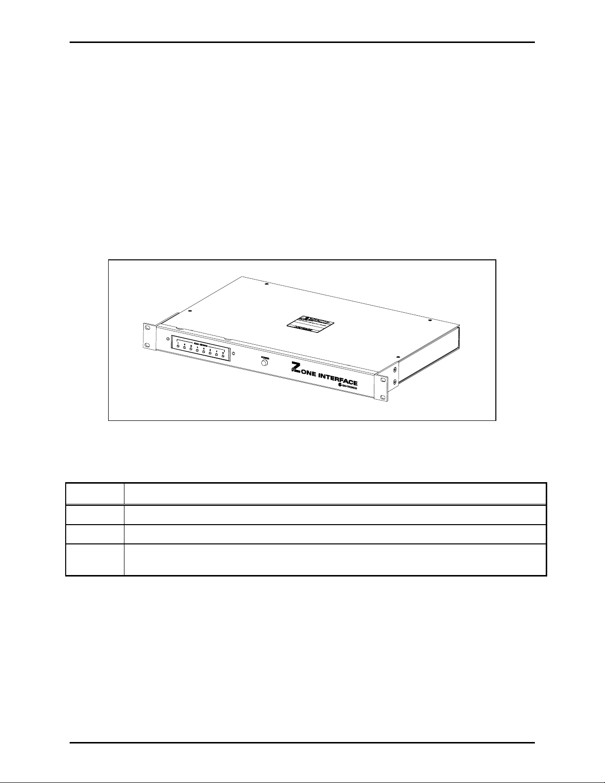
Figure 1. Zone Interface Module
GAI-Tro nics 109 60 Series Z one Inter face Mod ule Model Chart
Model Description
10960-001 Zone Interface Module with 8-Zone Amplifier Steering Module
10960-002 Zone Interface Module with 33-ohm Page/Party® Interface
10960-003
Zone Interface Module with 8-Zone Amplifier Steering Module and 33-ohm Page/Party
Interface
®
\\s_eng\gtc proddoc s \st andard iom s - current release\42004 instr. manuals \ 42004-369b. doc
08/05
Page 3
Pub. 42004-369B
10960 Series Zone Module Interface Page: 3 of 10
Specification s
Power Supply Requirements
Connection to a 12 to 24 V dc (UL listed) Class 2 power source.......................................1 amp minimum
Power consumed..........................................................................................................10 watts maximum
Mechanical
Enclosure............................................. Steel body with aluminum cover; black, fine-textured paint finish
Mounting ..........................................................................................Rack-mount; 1U in standard 19-inch
Dimensions ...................................................... 17.00 W × 11.18 D × 1.72 H inches; (432 × 284 × 44 mm)
Weight ............................................................................................................................8.5 lbs. (3.86 kg)
Enviro nmental
Temperature range................................................................................+32º F to +122º F (0º C to +50º C)
Installation
Power Disconnect. The power cord is the main power disconnect for all un its.
Disjontion de l’alimentation. Le cordon d’alimentation est la disjonction d’alimentation principale tous les appareils.
Para Desconectar la Alimentación: El cable de alimentación es el medio principal de desconexión del equipo.
Netzanschluß. Wenn man das Netzkabel aus der Steckdose zieht, dann ist die Spannungszuführung zum Gerät vollkommen
unterbrochen.
CAUTION To reduce the risk of fire, use only No. 26 AWG or larger telecommunicat ion line cord.
ATTENTION Pour réduire le risque d’incendie, utiliser uniquement des conducteurs de télécommunications 26 AWG ou
de section sup érieure.
PRECAUCIÓN Para aminorar la posibilidad de in cendios, utili ce s olam ente cable de telecomun icaciones de calibre 26
(sistema AWG americano) o mayor.
VORSICHT Um die Brandgefahr zu verrin gern, verwenden Sie bit te nur Fernmeldekabel der Stärke Nr. 26 AWG oder
höher.
\\s_eng\gtc proddoc s \st andard iom s - current release\42004 instr. manuals \ 42004-369b. doc
08/05
Page 4

Pub. 42004-369B
10960 Series Zone Module Interface Page: 4 of 10
Mounting
The Model 10960 Series Rack-Mount ZIM units can be placed on a table or desk, or it can be mounted in
a standar d EIA 19-i nc h electronic equ ipment rack. The ZIM units require 1U (1.75 inches) in a standard
19-inch rack. If the ZIM is installed in an electronic equipment rack, complete the following steps:
1. Install the mounting brackets with the eight 8–32 × 3/8-inch screws provided.
2. Mount the ZIM into the rack using the four 10–32 × ¾-inch screws provided.
Tablet op Mounti ng
If the ZIM is to be placed on a table or desk, install the five stabilizing feet and use the four #4
countersunk toothed washers when attaching the top to the base. These washers help to provide good
contact bet w een the two to ensure ad equa te grounding.
Wiring
WARNING
WARNING
Do not apply power until all the connections have been wired.
Connect only to a UL-listed Class 2 power source.
Figure 2. Power connections
Label Description Function
+ Power (+) 12 to 24 V dc power supply positive terminal
- Power (-) 12 to 24 V dc power supply negative terminal
Ground Earth ground
\\s_eng\gtc proddoc s \st andard iom s - current release\42004 instr. manuals \ 42004-369b. doc
08/05
Page 5

Pub. 42004-369B
10960 Series Zone Module Interface Page: 5 of 10
Figu re 3. ZIM Rear Pan el
Audio ( Communicat ion)
Terminal Labeled Description Function
1 - Data (-) Connect to AMI Models 10959-xxx (TB3-9)
2 + Data (+) Connect to AMI Models 10959-xxx (TB3-10)
3 GND Data (Gnd) Connect to AMI Models 10959-xxx (TB3-8)
4 PG MON Page monitor No connection (future use)
5 PGND Power ground Connect to AMI Models 10959-xxx (TB3-7)
6 SPARE Spare No connection
7 SPARE Spare No connection
8 SPARE Spare No connection
Audio
Terminal Labeled Description Function
1
2
600Ω
600Ω
(L1)
(L2)
Page (L1) Connect to AMI Models 10959-xxx (TB3-1)
Page (L2) Connect to AMI Models 10959-xxx (TB3-2)
3 AUDIO2 (L1) Audio 2 (L1) C onnect to AMI Models 10959-xxx (TB3-3)
4 AUDIO2 (L2) Audio 2 (L2) C onnect to AMI Models 10959-xxx (TB3-4)
5 AUDIO1 (L1) Audio 1 (L1) C onnect to AMI Models 10959-xxx (TB3-5)
6 AUDIO1 (L2) Audio 1 (L2) C onnect to AMI Models 10959-xxx (TB3-6)
\\s_eng\gtc proddoc s \st andard iom s - current release\42004 instr. manuals \ 42004-369b. doc
08/05
Page 6

Pub. 42004-369B
10960 Series Zone Module Interface Page: 6 of 10
Line Audi o Output s 1
Terminal Labeled Description Function
1 GND Power ground
2 OUT 1 (L1) Audio out Zone 1 (L1)
Zone 1 Output Balanced 600 Ω
3 OUT 1 (L2) Audio out Zone 1 (L2)
4 OUT 2 (L1) Audio out Zone 2 (L1)
Zone 2 Output Balanced 600 Ω
5 OUT 2 (L2) Audio out Zone 2 (L2)
6 OUT 3 (L1) Audio out Zone 3 (L1)
Zone 3 Output Balanced 600 Ω
7 OUT 3 (L2) Audio out Zone 3 (L2)
8 OUT 4 (L1) Audio out Zone 4 (L1)
Zone 4 Output Balanced 600 Ω
9 OUT 4 (L2) Audio out Zone 4 (L2)
10 GND Power ground
Line Audi o Output s 2
Terminal Labeled Description Function
1 GND Power ground
2 OUT 5 (L1) Audio out Zone 5 (L1)
3 OUT 5 (L2) Audio out Zone 5 (L2)
4 OUT 6 (L1) Audio out Zone 6 (L1)
5 OUT 6 (L2) Audio out Zone 6 (L2)
6 OUT 7 (L1) Audio out Zone 7 (L1)
7 OUT 7 (L2) Audio out Zone 7 (L2)
8 OUT 8 (L1) Audio out Zone 8 (L1)
9 OUT 8 (L2) Audio out Zone 8 (L2)
10 GND Power ground
Zone 5 Output - Balanced - 600 Ω
Zone 6 Output - Balanced - 600 Ω
Zone 7 Output - Balanced - 600 Ω
Zone 8 Output - Balanced - 600 Ω
\\s_eng\gtc proddoc s \st andard iom s - current release\42004 instr. manuals \ 42004-369b. doc
08/05
Page 7

Pub. 42004-369B
10960 Series Zone Module Interface Page: 7 of 10
Page/Party® System
Terminal Labeled Description Function
1 PG (L1) Page (L1)
Connects to the page line of Page/Party
®
system
2 PG (L2) Page (L2)
3 PTY1 (L1) Party 1 (L1)
4 PTY1 (L2) Party 1 (L2)
5 PTY2 (L1) Party 2 L1)
6 PTY2 (L2) Party 2 (L2)
7 PTY3 (L1) Party 3 (L1)
8 PTY3 (L2) Party 3 (L2)
9 PTY4 (L1) Party 4 (L1)
10 PTY4 (L2) Part y 4 (L2)
11 PTY5 (L1) Part y 5 (L1)
12 PTY5 (L2) Part y 5 (L2)
Connects to the party 1 line of Page/Party
system
Connects to the party 2 line of Page/Party
system
Connects to the party 3 line of Page/Party
system
Connects to the party 4 line of Page/Party
system
Connects to the party 5 line of Page/Party
system
®
®
®
®
®
Setup
Preparation
When the unit is ready for testing, please ensure the ZIM is installed and connections are made consistent
with the Wiring section on page 4. Please verify the following:
• DC power connect ed a nd polarity is correct
• Inputs are connected
• Outputs are connected
• Phone line is connected (if applicable)
• Page and party lines are connected (if applicable)
• Paging amplifier is connected (if using 600-ohm output)
• Resistive line balance is installed to support the Page line.
• Existing party line resistive line balancing is disconnected.
\\s_eng\gtc proddoc s \st andard iom s - current release\42004 instr. manuals \ 42004-369b. doc
08/05
Page 8

Pub. 42004-369B
10960 Series Zone Module Interface Page: 8 of 10
Operation
Remote Commands
After a ca ll has b een conn ected to the AMI with a ZIM , t he call er can enter a valid remot e co mmand
using the DTMF keypad of the telephone. During the greeting message, the caller must enter a DTMF
“*” t o access re mote contro l. The greeting messa ge wil l be halted, and two consecutive beeps w ill sound,
indi c atin g the unit has ent ered re mo te contr ol mode.
Callers can direct a page to a specific zone group by entering a DTMF “#”, followed by the two-digit
zone group number. Valid zone group numbers are 01 - 60. Entering #00 selects the all-call feature.
Additional remote commands are available for wall-mount AMI units equipped with the 33-ohm
Page/Party
conversation. After entering remote control mode, the caller enters a DTMF “*”, followed by the singledigit party line (1 through 5). The AMI will continue with live page or recorded paging, depending upon
the configured page mode. When the page is answered, the caller is connected to the selected party line.
The Off-hook Timeout setting for the Telephone Interface in the ACT tool limits the duration of a party
conversation. Approximately 20 seconds prior to the configured timeout expiration, the AMI will emit a
warning tone, indicating that the connected call is about to be terminated. If the caller enters the DTMF
“*” key, the AMI extends the conversation by the length of time defined by the Off-hook Timeout
parameter. Two consecutive beeps a re sounded when the AMI t i meou t has b een su ccessfully ext en ded.
While a caller is waiting for the paged party to respond, entering the DMTF “#” causes the AMI to restart
paging. Caller s can either reissue a page f or th e original p art y, or ma ke a page for anoth er pa r ty.
OTE: The caller does not access remote control mode to extend the connected party conversation or to
N
reissue a page.
®
Interface. Callers can choose the party line that will be connected for a subsequent telephone
Maintenance
If your ZIM unit requires service, contact your GAI-Tronics Regional Service Center for a return
authorization nu mber ( RA#). Equipment should be shippe d prepaid t o GAI-Tron i c s with a return
authorization number and a purchase order number. If the equipment is under warranty, repairs will be
made without charge. Please include a written explanation of all defects to assist our technicians in their
tr oubleshootin g e f for ts.
Call 800-492-1212 inside the USA or 610-777-1374 outside the USA for help identifying the Regional
Service Center closest to y o u.
\\s_eng\gtc proddoc s \st andard iom s - current release\42004 instr. manuals \ 42004-369b. doc
08/05
Page 9

Pub. 42004-369B
10960 Series Zone Module Interface Page: 9 of 10
Description of Major Components
Internal Components
The ZI M cont ains the PCBAs a s listed below. Refer to Figu re 4 for mounting locations.
• Amplifier Steering Module PCBA
• LED Module
• Power Supply PCBA
®
• Page/Party
Interface PCBA
Figure 4. Model 10960-003 Zone Interface Module - Interior
Internal Cable Connecti ons
The following is a matrix showing the connections for the ZIM internal components:
PCBA/Component Connector Matrix
Amplifier Steering Module PCBA
LED Module
Power Supply PCBA
Page/Party® Interface PCBA
Enclosure
\\s_eng\gtc proddoc s \st andard iom s - current release\42004 instr. manuals \ 42004-369b. doc
08/05
P4 P2 P3
P5
P4 P41 PS501 PS502 P6
P5 P4 TB1
(Rear)
P/P
system
(Front)
Power
LED
Page 10

Pub. 42004-369B
10960 Series Zone Module Interface Page: 10 of 10
Figure 5. ZIM Front Panel
Audio O utput LEDs
The front panel Audio Output LEDs (1 through 8) indicate which of the ZIM’s eight audio paths are
currently open.
Power LED
The ZIM unit’s front panel power LED indicates that an external power supply (12 to 24 V dc) is
connected.
Replaceme nt Parts
Part Numb e r Description
69451-001 Amplifier Steering Module
69452-001 Auxiliary Power Module
69502-101 Page/Party® Interface Module
Wall Pack 120 V ac/12 V dc @ 1 A
Confidentiality Notice
This manua l is provide d sole ly as an operatio nal, installation, and ma inte nance guide and conta ins
sensitive business and t e chnical informatio n tha t is confidentia l and pr opri et ary to GAI- Tronics.
GAI-Tr on ic s ret ains a ll intellec tua l prop erty and other ri ghts in or t o the informa tion c onta ined herei n, and
such information may on ly be u sed in conn e ction with the operatio n of you r GAI-Tr onics p rodu c t or
system. This manu al may not be dis clos e d in any form, in whole or in pa rt, direct ly or i ndir ectly, to a ny
third pa r ty.
\\s_eng\gtc proddoc s \st andard iom s - current release\42004 instr. manuals \ 42004-369b. doc
08/05
 Loading...