

Page 1

Pub. 42004-404G
GAI-TRONICS®
A H U B B E L L C O M P A N Y
Models 10959-207 and -208 Rack-Mount
Audio Messenger Interface
T A B L E O F C O N T E N T S
Confidentiality Notice .....................................................................................................................1
Product Overview ............................................................................................................................1
Features .................................................................................................................................................... 1
Options ..................................................................................................................................................... 2
Functions .................................................................................................................................................. 2
Alarms ................................................................................................................................................... 2
Inputs/Outputs ....................................................................................................................................... 2
Timed Events ........................................................................................................................................ 2
Optional Telephone Operation (Model 10959-208 only) ..................................................................... 3
Page/Party® Operation .......................................................................................................................... 3
Optional ADVANCE Operation ........................................................................................................... 3
Optional Zone Operation ...................................................................................................................... 4
Optional AMI Redundancy ................................................................................................................... 4
Installation ......................................................................................................................................4
Mounting .................................................................................................................................................. 5
Desktop installations ............................................................................................................................. 5
Rack Installations .................................................................................................................................. 5
Field Wiring ............................................................................................................................................. 6
Digital Outputs ...................................................................................................................................... 6
Digital Inputs ........................................................................................................................................ 7
Audio..................................................................................................................................................... 8
System ................................................................................................................................................... 8
Ethernet ................................................................................................................................................. 9
Power .................................................................................................................................................... 9
Optional PBX Connection (Model 10959-208 only) ............................................................................ 9
Page/Party® ........................................................................................................................................... 9
Auxiliary Microphone ......................................................................................................................... 10
Settings and Adjustments ..............................................................................................................11
Opening the Unit ................................................................................................................................... 11
Level Adjustments ................................................................................................................................ 12
Display Brightness .............................................................................................................................. 12
Phone Line Levels ............................................................................................................................... 12
Party Line Levels ................................................................................................................................ 12
Page Line Levels ................................................................................................................................. 12
Jumper Settings ..................................................................................................................................... 12
600-Ohm Line Termination ................................................................................................................ 12
AUDBUS1 Termination ..................................................................................................................... 12
GAI-TRONICS 3030 KUTZTOWN RD. READING, PA 19605 USA
610-777-1374 800-492-1212 Fax: 610-796-5954
VISIT WWW.GAI-TRONICS.COM FOR PRODUCT LITERATURE AND MANUALS
Page 2

Table of Contents Pub. 42004-404G
AUDBUS2 Termination ..................................................................................................................... 12
Audio Contact Supervision ................................................................................................................. 12
Date and Time Set Up ........................................................................................................................... 14
Date Set Up ......................................................................................................................................... 14
Time Set Up ........................................................................................................................................ 14
AMI Configuration Tool (ACT) ...................................................................................................14
Overview ................................................................................................................................................ 14
System Requirements ........................................................................................................................... 14
Configurable Parameters ..................................................................................................................... 15
Fragments ............................................................................................................................................ 15
Messages ............................................................................................................................................. 15
Inputs................................................................................................................................................... 15
Outputs ................................................................................................................................................ 15
Event Scheduling ................................................................................................................................ 15
Optional Telephone Interface .............................................................................................................. 16
Page/Party® Interface .......................................................................................................................... 16
Optional Zone Groups ......................................................................................................................... 16
CompactFlash® ...................................................................................................................................... 16
Operation .......................................................................................................................................17
LCD Display at Initial Power Up......................................................................................................... 17
LCD Display during Operation ........................................................................................................... 18
Push-Button Menu Operation ............................................................................................................. 19
Stop Message ...................................................................................................................................... 19
Play Message ...................................................................................................................................... 19
Firmware Update ................................................................................................................................ 19
Reset AMI ........................................................................................................................................... 19
Return .................................................................................................................................................. 19
Specifications ................................................................................................................................20
Power Supply ......................................................................................................................................... 20
Audio ...................................................................................................................................................... 20
Communications ................................................................................................................................... 20
I/O Control ............................................................................................................................................ 20
Environmental ....................................................................................................................................... 21
FCC Information .................................................................................................................................. 21
Approvals .......................................................................................................................................21
Replacement Parts.........................................................................................................................21
GAI-TRONICS 3030 KUTZTOWN RD. READING, PA 19605 USA
610-777-1374 800-492-1212 Fax: 610-796-5954
VISIT WWW.GAI-TRONICS.COM FOR PRODUCT LITERATURE AND MANUALS
Page 3
Pub. 42004-404G
GAI-TRONICS®
A HUBBELL COMPANY
Models 10959-207 and -208 Rack-Mount
Audio Messenger Interface
Confidential ity Notice
This manual is provided solely as an installation, operation, and maintenance guide and contains sensitive
business and technical information that is confidential and proprietary to GAI-TRONICS. GAITRONICS retains all intellectual property and other rights in or to the information contained herein, and
such information may only be used in connection with the operation of your GAI-TRONICS product or
system. This manual may not be disclosed in any form, in whole or in part, directly or indirectly, to any
third party.
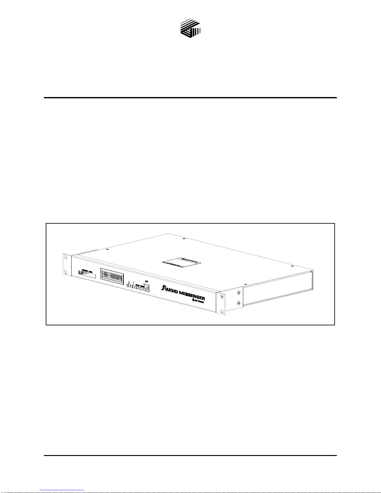
Product Overview
The GAI-TRONICS AMI (Audio Messenger Interface) tone/speech generator broadcasts live pages,
telephone pages, pre-recorded alarm tones, pre-recorded speech messages, etc., for use in virtually any
application.
Figure 1. Rack-Mount Audio Messenger Interface
Fea tures
recorded alarm tones
eight inputs and eight outputs upgradeable to
40 inputs and outputs
600-ohm, 1 V
CompactFlash
audio output
RMS
®
memory
ACT (AMI Configuration Tool) PC software
scheduled events
day/night modes
live/recorded speech messages
®
integration to Page/Party
systems
GAI-TRONICS 3030 KUTZTOWN RD. READING, PA 19605 USA
610-777-1374 800-492-1212 Fax: 610-796-5954
ISIT WWW.GAI-TRONICS.COM FOR PRODUCT LITERATURE AND MANUALS
V
Page 4

Pub. 42004-404G
Model
Description
10959-207
AMI, rack-mount with Page/Party® interface
10959-208
AMI, rack-mount with Page/Party® and telephone interfaces
12584-001
I/O control module option
XDM002A
desktop paging microphone
10960-001
zone interface module
10962-00x
AMI redundancy controller
Models 10959-207 and -208 Rack-Mount Audio Messenger Interface Page 2 of 21
Options
telephone access
desktop paging microphone
up to 40 general inputs and 40 general outputs
routability to eight controlled audio zones
AMI redundancy for system reliability
integration to ADVANCE systems
Table 1. Rack-Mount AMI Models and Accessories
Functions
Alarms
The ACT tool includes pre-recorded tones suitable for almost any application. The tones include typical
emergency tones (i.e., a siren, slow whoop, etc.) and signaling or process tones (i.e., a gong, steady tone,
etc.). All of the tones and speech messages broadcast by the AMI are stored in MP3 file format. For
applications where a required tone is not supplied, any tone recorded or stored in an MP3 file format can
be used with the AMI.
Inputs/Outputs
The AMI includes eight configurable inputs and outputs. Inputs are typically configured to activate tones
and/or speech messages, mute audio playback, or reset alarms. Outputs are typically used to activate
external signaling devices, interface to automated control systems, or interface to paging system
equipment.
An I/O control module can be added to the system if the standard eight inputs and outputs are not
sufficient for an application. The I/O control module provides an additional 32 inputs and 32 digital
outputs expanding the total possible inputs and outputs to 40 of each.
Timed Events
The AMI has the capability to perform several functions based on the time of day. Events can be
scheduled to occur at any interval (hourly, daily, weekly, and monthly, etc.). Scheduled events are
configured using the ACT software.
P:\Standard IOMs - Current Release\42004 Instr. Manuals\42004-404G.docx
08/18
Page 5

Pub. 42004-404G
Models 10959-207 and -208 Rack-Mount Audio Messenger Interface Page 3 of 21
Optional Telephone Operation (Model 10959-208 only)
The Model 10959-208 AMI can provide passcode-protected telephone access to the system to allow
telephone access only if the correct Remote Access Security Code is entered. The remote access code is
used to prevent unwanted callers from directly accessing the system. Callers must enter the correct
security code to gain access to the system if the system is configured to use a security code. Day and
night modes can have different security codes.
The telephone interface has multiple operational modes. Configure the appropriate mode using the ACT
software application.
The operational modes of operation are as follows:
Page/Party®—Delivers live voice pages (not pre-recorded) to the page line output.—The party line is
held open following the page.
Record Page—Records each page before delivery to the page line output.
Mixed Mode—Records a page, delivers it to the page line output, and holds the party line open
following the page.
Live Page Mode—Delivers a live voice page (not pre-recorded) to the page line output. The party
line is not open following the page.
Ring Mode—Plays a preconfigured message on the page line to signal an incoming call.
Manual/Disabled—The telephone interface does not automatically answer a phone call. However, an
input can be configured for manual access to allow an attendant to manually answer the phone, and
transfer calls to a party line.
The AMI can support two temporal modes of operation: day mode and night mode. The day mode and
night mode can be configured independently of each other. As an example of different day and night
modes; the day mode may be configured to allow callers to page and wait for a subsequent party line
communication, while the night mode is configured to play a tone over the paging system alerting
personnel of an incoming call. The call can be answered at any Page/Party® station in this mode.
Page/Party® Operation
Page/Party® operation allows the AMI to play messages/alarms and connect phone calls (Model 10959-
208) to a Page/Party® system.
Page/Party® operation has the ability to generate the VLC tone during a message/alarm that gives
Page/Party® stations a signal to change the volume of the message/alarm being played.
The operation of the Model 10959-209 telephone interface works as described above when the AMI is
interfaced to a Page/Party® system. The party line used for telephone operation in a Page/Party® system
is hardwired in the system, and cannot be changed by the caller or the AMI configuration.
A user on a Page/Party® system can also initiate a call using a feature called party hot dial. Party hot dial
is configure with the ACT tool and allows the AMI to recognize when a station has gone off-hook on a
designated party line. The AMI then connects that party line to the telephone interface and automatically
dials a preprogrammed telephone number. The call is terminated after a hang-up delay when the station is
placed back on-hook.
Optional ADVANCE Operation
Page/Party® operation allows an AMI to play messages/alarms and connect phone calls to an ADVANCE
system. The operation of the telephone interface includes all page modes as described above when the
Model 10959-209 AMI is interfaced to an ADVANCE system.
P:\Standard IOMs - Current Release\42004 Instr. Manuals\42004-404G.docx
08/18
Page 6

Pub. 42004-404G
DANGER
DANGER
DANGER
DANGER
DANGER
DANGER
DANGER
DANGER
DANGER
DANGER
DANGER
DANGER
Models 10959-207 and -208 Rack-Mount Audio Messenger Interface Page 4 of 21
Scheduled events and live pages can be played through the ADVANCE system to a specified zone group.
Zone groups are configured using the ACT tool and the ADVANCE system configuration software.
Configured zone groups can be assigned to individual events, messages, or the AMI auxiliary microphone
jack.
NOTE: Party lines one and two must be used in an ADVANCE system, and cannot be changed by the
caller or the AMI configuration.
Refer to the Jumper Settings section when the AMI is used in an ADVANCE system.
Optional Zone Operation
The optional zone interface module allows the AMI to route audio to eight individually controlled zones.
Each zone provides a 0 dBm/600-ohm output. Use the ACT tool to assign zones to zone groups. A zone
group is assigned a unique description and can consist of any combination of zones. A maximum of 60
zone groups can be created. Use the ACT tool to assign various events and messages to each zone group.
Telephone callers can use DTMF signaling to select the zone group prior to making a page.
Optional AMI Redundancy
The optional ARC (AMI Redundant Controller) provides the capability to increase system reliability by
using two AMI units; one as the primary, and one as a backup. The ARC module(s) control which AMI
is active and which is the backup.
During normal alarm operation, input contacts are applied simultaneously to both the active and back-up
AMIs. The ARC module(s) allow only the active generator to play the tone/speech message over the
system speakers. The backup AMI is held in standby mode to prevent audio mixing of the two AMI
tone/speech messages.
In the event of a failure of the active AMI, the backup AMI becomes active and plays its tone/speech
message over the system speakers.
Installation
—Power Disconnect—The power cord is the main power disconnect for all units.
—Disjontion de l’alimentation—Le cordon d’alimentation est la disjonction d’alimentation principale tous les appareils.
—Para Desconectar la Alimentación—El cable de alimentación es el medio principal de desconexión del equipo.
—Netzanschluß—Wenn man das Netzkabel aus der Steckdose zieht, dann ist die Spannungszuführung zum Gerät vollkommen
CAUTION
unterbrochen.
—To reduce the risk of fire, use only No. 26 AWG or larger telecommunication line cord.
ATTENTION
PRECAUCIÓN
VORSICHT
P:\Standard IOMs - Current Release\42004 Instr. Manuals\42004-404G.docx
08/18
—Pour réduire le risque d’incendie, utiliser uniquement des conducteurs de télécommunications 26 AWG ou de
section supérieure.
—Para aminorar la posibilidad de incendios, utilice solamente cable de telecomunicaciones de calibre 26
(sistema AWG americano) o mayor.
—Um die Brandgefahr zu verringern, verwenden Sie bitte nur Fernmeldekabel der Stärke Nr. 26 AWG oder höher.
Page 7
Pub. 42004-404G
Models 10959-207 and -208 Rack-Mount Audio Messenger Interface Page 5 of 21
Mounting
The Model 10959-207 and -208 Rack-Mount AMI units can be placed on a table or desk, or can be
mounted in a standard EIA 19-inch electronic equipment rack.
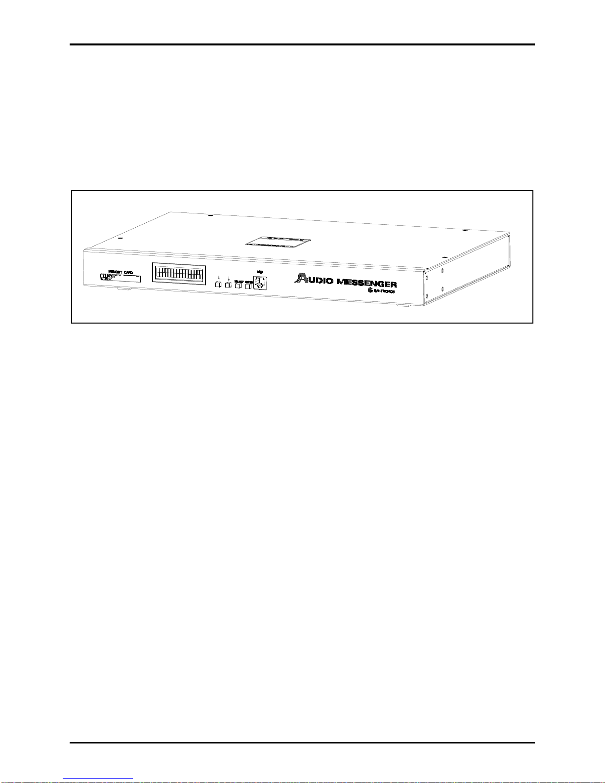
Desktop installations
1. Install the five stabilizing feet.
2. Attach the top to the base with the four #4 countersink toothed washers and screws. These washers
help provide good contact to ensure adequate grounding.
Figure 2. AMI with feet for tabletop
Rack Installations
The 10959-207/-208 AMI requires 1U (1.75 inches) in a standard 19-inch rack.
1. Install the mounting brackets with the eight 8–32 × 3/8-inch screws provided.
2. Mount the AMI into the rack using the four 10–32 × ¾-inch screws provided.
P:\Standard IOMs - Current Release\42004 Instr. Manuals\42004-404G.docx
08/18
Page 8
Pub. 42004-404G
Models 10959-207 and -208 Rack-Mount Audio Messenger Interface Page 6 of 21
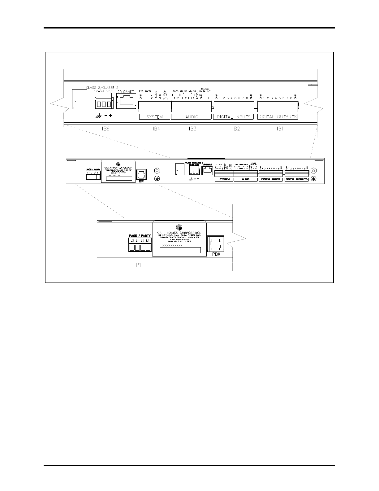
Field Wiring
Figure 3. Back of rack with connections labeled
Digital Outputs
Terminal block TB1, labeled DIGITAL
OUTPUTS, is located on the rear of the AMI. It provides eight
digital common ground outputs. The outputs are open collector active low. The controlled circuit must
use the same voltage used to power the AMI. The ground or dc common terminals for the controlled
circuits must be tied to GND on the terminal block. Each output can supply 100 mA maximum current.
P:\Standard IOMs - Current Release\42004 Instr. Manuals\42004-404G.docx
08/18
Page 9

Pub. 42004-404G
Metalwork
Label
Internal
Terminal Pin-Out
Function or ACT
Description
GND
TB1-1
Ground or dc common
1
TB1-2
Output 1
2
TB1-3
Output 2 3 TB1-4
Output 3
4
TB1-5
Output 4
5
TB1-6
Output 5 6 TB1-7
Output 6
7
TB1-8
Output 7
8
TB1-9
Output 8
GND
TB1-10
Ground or dc common
Metalwork
Label
Internal
Terminal Pin-Out
Function or ACT
Description
GND
TB2-1
Ground or dc common
1
TB2-2
Input 1 2 TB2-3
Input 2
3
TB2-4
Input 3
4
TB2-5
Input 4
5
TB2-6
Input 5 6 TB2-7
Input 6
7
TB2-8
Input 7
8
TB2-9
Input 8
GND
TB2-10
Ground or dc common
Models 10959-207 and -208 Rack-Mount Audio Messenger Interface Page 7 of 21
Table 2. Digital Output Connections
Digital Inputs
Terminal block TB2, labeled DIGITAL INPUTS, is located on the rear of the AMI. It provides eight
digital common ground inputs. The input contacts are configured as any combination of momentary
(pulsed) switches and maintained (latched) switches. They can be either NO (normally open) or NC
(normally closed) dry contacts rated at 5 mA or better. The ground or dc common terminals for the
controlled circuits must be tied to GND on the terminal block.
NOTE: The cable loop resistance connecting the relay/switch contact closures cannot exceed 200 ohms
for the inputs to operate reliably.
Table 3. Digital Input Connections
P:\Standard IOMs - Current Release\42004 Instr. Manuals\42004-404G.docx
08/18
Page 10

Pub. 42004-404G
Metalwork
Label
Internal Terminal
Pin-Out
Function or ACT Description
600 OHM L1
TB3-1
page output audio to public address amplifier,
ADVANCE system, or zone interface module
600 OHM L2
TB3-2
AUDBUS2 L1
TB3-3
internal audio bus and ADVANCE, ARC, or
party audio from AMI
AUDBUS2 L2
TB3-4
AUDBUS1 L1
TB3-5
internal audio bus and ADVANCE party audio to
AMI
AUDBUS1 L2
TB3-6
PGND
TB3-7
power supply ground
RS485 INT GND
TB3-8
no connection
RS485 INT −
TB3-9
data/ground connection for I/O control module
RS485 INT +
TB3-10
Metalwork
Label
Internal Terminal
Pin-Out
Function or ACT Description
EXT DATA GND
TB4-1
no connection
EXT DATA-
TB4-2
data connection for ADVANCE or external CPU
control
EXT DATA+
TB4-3
FLT
TB4-4
active high signal representing a fault with AMI
REBOOT
TB4-5
momentary active low signal to reboot AMI
GND
TB4-6
ground reference for FLT and REBOOT
AUD ACT 1
TB4-7
isolated SSR—closed during AMI page
On resistance = 30 ohms
AUD ACT 2
TB4-8
Models 10959-207 and -208 Rack-Mount Audio Messenger Interface Page 8 of 21
Audio
Terminal block TB3, labeled AUDIO, is located on the rear of the AMI. It provides connections for audio
inputs, audio outputs, and local RS-485 data connections. Audio connections to a public address
amplifier require shielded pair conductors. Local data connections are used with the I/O control module
and/or the zone interface module.
Table 4. Audio/RS485 Connections
System
Terminal block TB4, labeled SYSTEM, is located on the rear of the AMI. It provides connections for
system applications such as system reboot, fault indicator, and external data communications.
Table 5. System Connections
P:\Standard IOMs - Current Release\42004 Instr. Manuals\42004-404G.docx
08/18
Page 11

Pub. 42004-404G
Termination
PCBA Label
Internal
Terminal Pin-Out
Function or ACT Description
+
TB6-1
positive terminal of external power supply
(black wire with white stripe from power supply)
−
TB6-2
negative terminal of external power supply
(solid black wire from power supply)
GND
TB6-3
frame ground
PPI PCBA
Label
Internal
Terminal Pin-Out
Function or ACT Description
PARTY L1
P1-1
33-ohm line interface to GAI-TRONICS party line
internal 33-ohm termination
PARTY L2
P1-2
PAGE L1
P1-3
33-ohm line interface to GAI-TRONICS page line
external 33-ohm termination required
PAGE L2
P1-4
Models 10959-207 and -208 Rack-Mount Audio Messenger Interface Page 9 of 21
Ethernet
The Ethernet connector is reserved for future implementation.
Power
Terminal block TB6, labeled CLASS 2 12 –24 VDC, is located on the rear of the AMI. It provides the
required 12–24 V dc power connection to the AMI.
Table 6. Input Power Connection
Optional PBX Connection (Model 10959-208 only)
The connector labeled PBX on the rear of the AMI provides connectivity to a standard PBX analog
station port. Connect the telephone cable to the PBX jack with an RJ11 plug.
Page/Party®
Connector P1, labeled PAGE/PARTY, is located on the back of the AMI and provides connectivity to a
Page/Party® system.
Table 7. Page/Party® Connections
NOTE: Pin 1 on this connector is on the right side.
P:\Standard IOMs - Current Release\42004 Instr. Manuals\42004-404G.docx
08/18
Page 12

Pub. 42004-404G
Pin
Label
Function
1
HEADSET_RX_AUD
headset receive audio
2
RS232_RXD
RS-232 receive
3
PTT
Push-to-Talk
4
MIC_HI
microphone high
5
MIC_LO
microphone low
6
MONITOR
Monitor
7
RS232_TXD
RS-232 transmit
8
PGND
Ground
Models 10959-207 and -208 Rack-Mount Audio Messenger Interface Page 10 of 21
Auxiliary Microphone
Jack J1, located on the front panel of the AMI, provides connectivity for an auxiliary microphone. The
pinout for the microphone jack is as follows:
Table 8. Auxiliary Microphone Jack Pinout
P:\Standard IOMs - Current Release\42004 Instr. Manuals\42004-404G.docx
08/18
Page 13

Pub. 42004-404G
Models 10959-207 and -208 Rack-Mount Audio Messenger Interface Page 11 of 21
Settings and Adjustments
Opening the Unit
Rack Installations:
1. Label and disconnect all wiring to the AMI.
2. Remove the four 10-32 ¾-inch screws holding the unit in the rack.
3. Pull the unit out of the rack.
All Installations:
4. Remove the four screws securing the cover to the enclosure.
5. Remove the cover from the AMI enclosure.
Figure 4. Model 10959-208 AMI without cover (all boards installed).
P:\Standard IOMs - Current Release\42004 Instr. Manuals\42004-404G.docx
08/18
Page 14

Pub. 42004-404G
Models 10959-207 and -208 Rack-Mount Audio Messenger Interface Page 12 of 21
Level Adjustments
Display Brightness
Adjust potentiometer R237, on the main PCBA, to change the brightness of the LCD display on the front
of the assembly.
Phone Line Levels
Two potentiometers on the optional telephone interface PCBA adjust the telephone audio levels:
Volume level from telephone line—Adjust the receiver volume potentiometer, R36.
Volume to telephone line—Adjust the transmit volume potentiometer, R1.
Party Line Levels
Two potentiometers on the Page/Party® Interface PCBA adjust the party line audio levels:
Volume level to party line—Adjust the party volume potentiometer, R66.
Sidetone level from party line—Adjust the party sidetone potentiometer, R30.
Page Line Levels
Two potentiometers on the Page/Party® Interface PCBA adjust the page line audio levels:
Volume level to the page line—Adjust the page volume potentiometer, R39.
Page line audio monitor level—Adjust the page monitor potentiometer, R69.
Jumper Settings
600-Ohm Line Termination
Terminate the 600-ohm audio lines with 600 ohms for impedance matching. Use jumper P5, located on
the termination board (see Figure 5), to configure impedance matching on the 600-ohm audio line
connections (see Table 9).
AUDBUS1 Termination
Terminate the AUDBUS1 connection with 600 ohms for impedance matching. Use jumper P1, located
on the termination board (see Figure 5), to configure impedance matching on the AUDBUS1 connection
(see Table 9).
AUDBUS2 Termination
Terminate the AUDBUS2 connection with 600 ohms for impedance matching. Use jumper P6, located
on the termination board (see Figure 5), to configure impedance matching on the AUDBUS2 connection
(see Table 9).
Audio Contact Supervision
Configure the audio contact (AUD ACT) as supervised or unsupervised. Use jumper P11, locate on the
termination board (see Figure 5), to configure the audio contact as supervised for use with an ADVANCE
cabinet, or as an isolated SSR contact (see Table 9).
P:\Standard IOMs - Current Release\42004 Instr. Manuals\42004-404G.docx
08/18
Page 15

Pub. 42004-404G
Models 10959-207 and -208 Rack-Mount Audio Messenger Interface Page 13 of 21
Figure 5. Termination PCBA
Table 9. Termination PCBA Jumper Functions
Jumper Output Position
P1
P5
P6
P11
TB3-5, 6
Audio bus 1
TB3-1, 2
600 ohms
TB3-3, 4
Audio bus 2
TB4-7, 8
Audio contact
1-2 600-ohm resistor connected (ADVANCE position)
2-3 Default: unterminated
1-2 600-ohm resistor connected (ADVANCE position)
2-3 Default: unterminated
1-2 600-ohm resistor connected (ADVANCE position)
2-3 Default: unterminated
1-2
2-3 Default: unsupervised
Function
Supervision resistor network, 4.7k in series, 15k in
parallel (ADVANCE position)
P:\Standard IOMs - Current Release\42004 Instr. Manuals\42004-404G.docx
08/18
Page 16

Pub. 42004-404G
Models 10959-207 and -208 Rack-Mount Audio Messenger Interface Page 14 of 21
Date and Time Set Up
Date Set Up
Use the push buttons located on the front of the AMI to set the date (see Figure 4 for the push-button
locations). Complete the following procedure to set the date:
1. Press <ENTER>, PB4, to enter the menu system.
2. Press <SELECT>, PB3, to scroll to the DATE: display.
3. Press <ENTER>, PB4, to enter the DATE set up.
4. Press <ENTER>, PB4, to confirm choice.
5. Press <UP>, PB1 or <DOWN>, PB2 to select the desired day.
6. Press <SELECT>, PB3, to scroll to the month.
7. Press <UP>, PB1 or <DOWN>, PB2 to select the desired month.
8. Press <SELECT>, PB3, to scroll to the year.
9. Press <UP>, PB1 or <DOWN>, PB2 to select the desired year.
10. Press <ENTER>, PB4, to accept the DATE setting.
Time Set Up
Use the push buttons located on the front of the AMI to set the time (see Figure 4 for the push-button
locations). Complete the following procedure to set the time:
1. Press <ENTER>, PB4, to enter the menu system.
2. Press <SELECT>, PB3, to scroll to the TIME: display.
3. Press <ENTER>, PB4, to enter the TIME: set up.
4. Press <ENTER>, PB4, to confirm choice.
5. Press <UP>, PB1 or <DOWN>, PB2 to select the desired hour.
6. Press <SELECT>, PB3, to scroll to the minute.
7. Press <UP>, PB1 or <DOWN>, PB2 to select the desired minute.
8. Press <Enter>, PB4, to accept the TIME: setting.
AMI Configuration Tool (ACT)
Overview
The ACT (Audio Messenger Interface Configuration Tool) software is used to define and change
configurations for the AMI, and is included with all models of AMI. To retrieve configurations and play
audio messages, the AMI accesses a CompactFlash® card. Each AMI is shipped with a CompactFlash®
card pre-programmed with the AMI Factory Default configuration.
Please refer to the ACT software online help for specific instructions.
System Requirements
The ACT software must be installed on a Windows PC (Windows® XP/7/10) equipped with a USB port.
A reader/writer capable of programming CompactFlash® memory cards must be connected to the USB
port. The CompactFlash® reader/writer is not included with the AMI.
P:\Standard IOMs - Current Release\42004 Instr. Manuals\42004-404G.docx
08/18
Page 17

Pub. 42004-404G
Models 10959-207 and -208 Rack-Mount Audio Messenger Interface Page 15 of 21
Configurable Parameters
Fragments
All tones and voice messages are digitally recorded and stored on the CompactFlash® card as audio
fragments stored in MP3 files.
Messages
Each message is a collection of fragments. The content of each message must be defined by selecting the
fragment(s) to be incorporated into the message. Other message parameters include:
message title
priority
volume
play mode and repeat interval
Inputs
Input circuits must be enabled or disabled. Program each enabled input circuit with the following
parameters:
title containing a brief text description of the input and its use
type of switch contact being used to activate the input (NO, NC)
action of the switch (maintained, momentary, toggle on/off)
function of the input (activate a message, reboot, mute, etc.)
Outputs
Output circuits must be enabled or disabled. Program each enabled output circuit with the following
parameters:
title containing a brief text description of the output and its use
mode of operation when active (maintained, flash, momentary, flicker)
activation assignment from an input or scheduled event
Event Scheduling
Use the event-scheduling feature to set up messages to automatically play at certain dates and times. Set
the following parameters when scheduling events:
start and stop times
start and stop dates
event duration and intervals
P:\Standard IOMs - Current Release\42004 Instr. Manuals\42004-404G.docx
08/18
Page 18

Pub. 42004-404G
Models 10959-207 and -208 Rack-Mount Audio Messenger Interface Page 16 of 21
Optional Telephone Interface
Configure the following parameters if using the telephone interface:
number of rings before answer
paging mode (live or recorded)
page delay, if recorded
maximum page duration
selection of a greeting message to be played to the caller
selection of a pre-announcement tone to be played to the PA system
Page/Party® Interface
The following parameters can be set for the Page/Party® Interface:
VLC activation
party hot dial
Optional Zone Groups
Zone groups are configured with a unique description, and assigned any combination of the eight
available output zones.
CompactFlash®
The CompactFlash® memory card stores the system configuration, speech messages, and alarm tones.
Complete the following instructions to install the memory card:
1. Insert the memory card through the rectangular MEMORY CARD slot on the AMI main board with
the label on the memory card facing up.
2. Slide the memory card in until it is fully seated in the slot.
When seated properly, the card protrudes approximately ¼ inch from the front of the socket.
NOTE: The memory card and its socket are keyed for proper insertion—do not force the card into the
socket.
3. Reboot the system so the AMI unit can read the memory card.
P:\Standard IOMs - Current Release\42004 Instr. Manuals\42004-404G.docx
08/18
Page 19

Pub. 42004-404G
Models 10959-207 and -208 Rack-Mount Audio Messenger Interface Page 17 of 21
Operation
The AMI operates based on system inputs and outputs or by manual operation after the CompactFlash®
has been programmed and installed in the unit.
LCD Display at Initial Power Up
The AMI completes a self-diagnostic of its settings at initial power up. The LCD display cycles through
the following messages:
AMI firmware version
boot DSP
media detected
EEPROM firmware version
DSP firmware version
progress bar/LOAD CONFIG
configuration version
configuration date and time
configuration file name
HIO (I/O control module) board firmware version or “HIO not installed.”
ASM (Zone Interface Module) board firmware version or “ASM not installed.”
Page/Party® board firmware version
AMI main board firmware version
telephone interface mode (if telephone interface installed)
telephone interface board firmware version or “Telephone Interface not installed.”
telephone interface greeting file name (if recording a new greeting)
AMI ready
time, page symbol/date
P:\Standard IOMs - Current Release\42004 Instr. Manuals\42004-404G.docx
08/18
Page 20

Pub. 42004-404G
The VU meter indicates the volume of a page playing.
Mute indicates the page audio is muted.
Progress bar indicates remaining time for the party line connection timeout.
Telephone handset indicates the AMI unit is being accessed via a telephone connection.
Microphone indicates a page from the auxiliary jack.
Off hook indicates that a digital input designated as party line off hook is active.
Right/left arrows indicate transmit and receive activity on the auxiliary jack or external RS-485.
Text display (scrolling) displays current system status, such as the name of the current message
playing, telephone connection status, and party connection status.
Rotating slash, when visible, indicates the AMI has a lower priority message pending, ready to be
played.
MIN
MAX
MAX
MIN
MID
Models 10959-207 and -208 Rack-Mount Audio Messenger Interface Page 18 of 21
LCD Display during Operation
The LCD uses various symbols to indicate AMI activity:
P:\Standard IOMs - Current Release\42004 Instr. Manuals\42004-404G.docx
08/18
Page 21

Pub. 42004-404G
Models 10959-207 and -208 Rack-Mount Audio Messenger Interface Page 19 of 21
Push-Button Menu Operation
Front panel push buttons provide menu access for various control features including; play a message, stop
a message, and firmware update.
Stop Message
This menu item halts the currently playing message. The button sequence is:
1. Press <ENTER>, PB4, to enter the menu system.
2. Press <ENTER>, PB4, to select the STOP: item.
3. Press <ENTER>, PB4, to confirm the selection.
Play Message
This menu item plays a specific message. Messages are grouped by priority (1 through 7). The button
sequence allows the user to select a message to be played from a specific priority group:
1. Press <ENTER>, PB4, to enter the menu system.
2. Press <SELECT>, PB3, to scroll to the PLAY: item.
3. Press <ENTER>, PB4, to enter the PLAY: item.
4. Press <SELECT>, PB3, to scroll to the message.
5. Press <ENTER>, PB4, to play the selected message.
Firmware Update
This menu item facilitates updating the firmware of the AMI main board. The button sequence used is:
1. Press <ENTER>, PB4, to enter the menu system.
2. Press <SELECT>, PB3, to scroll the menu to the FIRMWARE UPDATE: item.
3. Press <ENTER>, PB4, to select the FIRMWARE UPDATE: item.
4. Press <ENTER>, PB4, to confirm the selection.
Reset AMI
Complete the following menu sequence to restart the AMI:
1. Press <ENTER>, PB4, to enter the menu system.
2. Press <SELECT>, PB3, to scroll the menu to the SYSTEM REBOOT: item.
3. Press <ENTER>, PB4, to select the SYSTEM REboot: item.
4. Press <ENTER>, PB4, to confirm the selection.
Return
Select this menu item to return the system to normal operation mode:
1. Press <ENTER>, PB4, to enter the menu system
2. Press <SELECT>, PB3, to scroll the menu to the RETURN item
3. Press <ENTER>, PB4, to select the RETURN menu item and return to normal operating mode.
P:\Standard IOMs - Current Release\42004 Instr. Manuals\42004-404G.docx
08/18
Page 22

Pub. 42004-404G
Models 10959-207 and -208 Rack-Mount Audio Messenger Interface Page 20 of 21
Specifications
Power Supply
Voltage ................................................................................. 12 to 24 V dc (UL listed) Class 2 power source
(plug-in 12 V dc power supply included with AMI)
Current ................................................................................................................................... 1 A (minimum)
Power consumed ................................................................................................................. 10 W (maximum)
Audio
Speech capacity ........................................................................... 500 min with 512 Mb CompactFlash® card
Scheduled events ........................................................................................................................ 29 maximum
Frequency response ............................................................................. 250–6500 Hz, +0/−3 dB ref. to 1 kHz
Distortion ........................................................................................ <1% THD @ 1 kHz @ nominal settings
Outputs
600-ohm output ...................................................................................................................... 1 V
33-ohm page output ............................................................................................................ 1.5 V
33-ohm party output ............................................................................................................ 1.5 V
Telephone line output ........................................................................................................ −10 dBm nominal
nominal
RMS
nominal
RMS
nominal
RMS
Inputs
Telephone line input .......................................................................................................... −10 dBm nominal
33-ohm party input .............................................................................................................. 1.5 V
Microphone
nominal
RMS
Type ........................................................................................................................................... passive input
Input impedance ................................................................................................................................... > 2 kΩ
Nominal input level .......................................................................................................................... −20 dBm
Input Adjustment Range .......................................................................................................................... N/A
Communications
ADVANCE ......................................................................................................................................... RS-485
Phone line ............................................................................................................................................ DTMF
I/O Control
Digital outputs .......................................................................................................................... open collector
Maximum output sinks current ......................................................................................... 100 mA per output
Maximum output voltage ...................................................................................................AMI input voltage
Isolated output .......................................................... dry contact or GAI-TRONICS proprietary supervision
Digital inputs ..................................................................................................... open collector or dry contact
Mechanical
Material ................................................... steel body with aluminum cover; black, fine-textured paint finish
Mounting ........................................................................................................... 1-U in standard 19-inch rack
Connections....................................................................................... screw-type terminal blocks, phone jack
Dimensions ............................................................... 17.00 W × 11.18 D × 1.72 H in, (432 × 284 × 44 mm)
Weight .................................................................................................................................... 8.5 lb (3.86 kg)
P:\Standard IOMs - Current Release\42004 Instr. Manuals\42004-404G.docx
08/18
Page 23

Pub. 42004-404G
Model Number
Description
69517-204
Termination PCBA
69462-001
Telephone Interface PCBA
69463-001
AMI Single-Party Interface
49100-007
CompactFlash® Card (blank)
Models 10959-207 and -208 Rack-Mount Audio Messenger Interface Page 21 of 21
Environmental
Temperature range ................................................................................... +32 ºF to +122 ºF (0 ºC to +50 ºC)
FCC Information
Complies with CFR47, Part 15 ........................................................................................................... Class A
Approvals
Safety of Information Technology Equipment.......UL 60950, CAN/CSA-C22.2 No. 60950-00, IEC 60950
Replacement Parts
Table 10. Replacement Parts
P:\Standard IOMs - Current Release\42004 Instr. Manuals\42004-404G.docx
08/18
Page 24

Warranty
Equipment. GAI-Tronics warrants for a period of one (1) year from the date of shipment, that any
GAI-Tronics equipment supplied hereunder shall be free of defects in material and workmanship, shall
comply with the then-current product specifications and product literature, and if applicable, shall be fit
for the purpose specified in the agreed-upon quotation or proposal document. If (a) Seller’s goods prove
to be defective in workmanship and/or material under normal and proper usage, or unfit for the purpose
specified and agreed upon, and (b) Buyer’s claim is made within the warranty period set forth above,
Buyer may return such goods to GAI-Tronics’ nearest depot repair facility, freight prepaid, at which time
they will be repaired or replaced, at Seller’s option, without charge to Buyer. Repair or replacement shall
be Buyer’s sole and exclusive remedy. The warranty period on any repaired or replacement equipment
shall be the greater of the ninety (90) day repair warranty or one (1) year from the date the original
equipment was shipped. In no event shall GAI-Tronics warranty obligations with respect to equipment
exceed 100% of the total cost of the equipment supplied hereunder. Buyer may also be entitled to the
manufacturer’s warranty on any third-party goods supplied by GAI-Tronics hereunder. The applicability
of any such third-party warranty will be determined by GAI-Tronics.
Services. Any services GAI-Tronics provides hereunder, whether directly or through subcontractors,
shall be performed in accordance with the standard of care with which such services are normally
provided in the industry. If the services fail to meet the applicable industry standard, GAI-Tronics will
re-perform such services at no cost to buyer to correct said deficiency to Company's satisfaction provided
any and all issues are identified prior to the demobilization of the Contractor’s personnel from the work
site. Re-performance of services shall be Buyer’s sole and exclusive remedy, and in no event shall GAITronics warranty obligations with respect to services exceed 100% of the total cost of the services
provided hereunder.
Warranty Periods. Every claim by Buyer alleging a defect in the goods and/or services provided
hereunder shall be deemed waived unless such claim is made in writing within the applicable warranty
periods as set forth above. Provided, however, that if the defect complained of is latent and not
discoverable within the above warranty periods, every claim arising on account of such latent defect shall
be deemed waived unless it is made in writing within a reasonable time after such latent defect is or
should have been discovered by Buyer.
Limitations / Exclusions. The warranties herein shall not apply to, and GAI-Tronics shall not be
responsible for, any damage to the goods or failure of the services supplied hereunder, to the extent
caused by Buyer’s neglect, failure to follow operational and maintenance procedures provided with the
equipment, or the use of technicians not specifically authorized by GAI-Tronics to maintain or service the
equipment. THE WARRANTIES AND REMEDIES CONTAINED HEREIN ARE IN LIEU OF AND
EXCLUDE ALL OTHER WARRANTIES AND REMEDIES, WHETHER EXPRESS OR IMPLIED BY
OPERATION OF LAW OR OTHERWISE, INCLUDING ANY WARRANTIES OF
MERCHANTABILITY OR FITNESS FOR A PARTICULAR PURPOSE.
Return Policy
If the equipment requires service, contact your Regional Service Center for a return authorization number
(RA#). Equipment should be shipped prepaid to GAI-Tronics with a return authorization number and a
purchase order number. If the equipment is under warranty, repairs or a replacement will be made in
accordance with the warranty policy set forth above. Please include a written explanation of all defects to
assist our technicians in their troubleshooting efforts.
Call 800-492-1212 (inside the USA) or 610-777-1374 (outside the USA) for help identifying the
Regional Service Center closest to you.
(Rev. 10/06)
 Loading...