

Page 1

Pub.: 42004-398E
GAI-TRONICS® CORPORATION
A HUBBELL COMPANY
Wall-Mount Audio Messenger Interface
Models 10959-101, -102, -103, and -104
TABLE OF C ONTENTS
Getting Started.................................................................................................................................1
Product Overview...................................................................................................................................1
Features and Functions..........................................................................................................................1
Specifications...........................................................................................................................................6
Installation ......................................................................................................................................7
Mounting..................................................................................................................................................8
Wiring......................................................................................................................................................8
TB1 - Digital Output Connections........................................................................................................................9
TB2 - Digital Input Connections.........................................................................................................................10
TB3 - Audio Output and Data Connections........................................................................................................11
TB4 - Reboot and Fault Output...........................................................................................................................12
TB5 - Auxiliary Audio........................................................................................................................................13
TB6 - Power Connections...................................................................................................................................14
69517-202 Jumper Settings.................................................................................................................................14
Telephone Line Connection................................................................................................................................15
Page/Party® System Connections........................................................................................................................16
Setup..............................................................................................................................................18
Preparation............................................................................................................................................ 18
Setting the Date and Time....................................................................................................................19
Initiating a Page....................................................................................................................................19
Verifying Telephone-to-Page/Party® Operation................................................................................20
Operation.......................................................................................................................................21
LCD Display and Push-button Operation.......................................................................................... 21
Working with CompactFlash®.............................................................................................................25
CompactFlash® Memory Card Installation.........................................................................................................25
Saving Configurations to a CompactFla sh® Card...............................................................................................25
CompactFlash
®
Card Formatting.......................................................................................................................25
Overview of the AMI Configuration Tool (ACT).............................................................................. 26
Remote Commands...............................................................................................................................27
Maintenance..................................................................................................................................28
Description of Major Components......................................................................................................28
Internal Components...........................................................................................................................................28
GAI-Tronics Corporation 400 E. Wyomissing Ave. Mohnton, PA 19540 USA
610-777-1374 800-492-1212 Fax: 610-796-5954
V
ISIT WWW.GAI-TRONICS.COM FOR PRODUCT LITERATURE AND MANUALS
Page 2

Table of Contents Pub. 42004-398E
MODEL 10959-10X WALL-MOUNT AUDIO MESSENGER INTERFACE
Internal Cable Connections.................................................................................................................................29
External Components..........................................................................................................................................30
CompactFlash
®
Card Slot..................................................................................................................................30
LCD Display.......................................................................................................................................................30
Replacement Parts................................................................................................................................30
Confidentiality Notice...................................................................................................................30
f:\standard ioms - current release\42004 instr. manuals\42004-398e.doc
10/09
Page 3

PUB. 42004-398E
Wall-Mount Audio Messenger Interface
Models 10959-101, -102, -103, and -104
Getting Started
Product Overview
Thank you for your purchase of the GAI-Tronics Audio Messenger Interface. The Audio Messenger
Interface (AMI) tone/speech generator broadcasts live pages, telephone pages, pre-recorded alarm tones,
pre-recorded speech messages, etc., for use in virtually any application. For application examples, please
see the “Application Notes” on the AMI Configuration Tool CD.
Prior to installation of the AMI, we recommend you read the entire manual and inspect the contents of the
package to ensure the following are included:
• Audio Messenger Interface (See model chart on page 5.)
®
• CompactFlash
• AMI Configuration Tool (ACT) CD
• Product Evaluation Card – Please fill out and return at your earliest convenience
memory card
Features and Functions
The Audio Messenger Interface (AMI) is a tone/speech generator that can be tailored to broadcast
tones/speech messages for many applications. The following is a sample of the included and optional
features:
• AMI Configuration Tool Software,
complete with:
- Pre-recorded alarm tones
- Pre-recorded speech messages
• 8 inputs/outputs plus expansion option
• Real-time clock
• Option to route audio to 8 individually
controlled zones
The Audio Messenger Interface Configuration Tool (ACT) software is used to define and change
configurations for the Audio Messenger Interface (AMI), and is included with all models of AMI. To
retrieve configurations and play audio messages, the AMI accesses a CompactFlash
shipped with a CompactFlash
®
card pre-programmed with the AMI Factory Default configuration.
Using the ACT software, custom configurations are created. After a custom configuration is created, it
must be saved to the local hard drive (typically in the <drive>:\Program Files\AMI Configuration
Tool\AMI Configs folder). After the configuration is saved to the hard drive, it must be moved or copied
to the CompactFlash
OTE: Custom configurations cannot be saved directly to a CompactFlash
N
®
card using Windows Explorer.
• Scheduled events
• Live speech messages
• Telephone access with built-in feedback eliminator
• Secure telephone access
®
• Integration to Page/Party
systems
• Day/Night modes
• Integration to ADVANCE systems
• VLC Activation
®
card. Each AMI is
®
card.
GAI-Tronics Corporation 400 E. Wyomissing Ave. Mohnton, PA 19540 USA
610-777-1374 800-492-1212 Fax: 610-796-5954
V
ISIT WWW.GAI-TRONICS.COM FOR PRODUCT LITERATURE AND MANUALS
Page 4

Pub. 42004-398E
ODEL 10959-10X WALL-MOUNT AUDIO MESSENGER INTERFACE PAGE 2 of 31
M
The ACT tool includes pre-recorded tones suitable for almost any application. The tones include typical
emergency tones (i.e., a siren, slow whoop, etc.) and signaling or process tones (i.e., a gong, steady tone,
etc.). All of the tones and speech messages broadcast by the AMI are stored in MP3 file format. For
applications where a needed tone is not supplied, any tone recorded or stored in an MP3 file format can be
used with the AMI. Using the ACT software, any MP3 audio file can be configured for use with the
AMI.
Additionally, because all audio is in MP3 format, custom speech messages can be recorded and
configured for use with the AMI. Using commercially available audio editing software, custom
fragments can be recorded onto the PC and stored in MP3 format. For example, to play a speech message
and alarm tone simultaneously, the speech can be recorded on the right channel and the tone on the left
channel. When broadcast by the AMI, the result will be a speech-over-tone message.
The ACT software must be installed on a Windows PC (Windows 98 SE/XP/2000) equipped with a USB
port. A reader/writer capable of programming CompactFlash
USB port. The CompactFlash
®
reader/writer is not included with the AMI.
®
memory cards must be connected to the
The AMI includes eight configurable inputs and outputs. Typically, the inputs are configured to activate
alarm/process tones and/or pre-recorded speech messages, mute audio playback, and reset alarms. The
outputs are typically used to activate remote alarm systems, interface to automated processes, interface to
paging system equipment, etc.
If the standard eight inputs are not sufficient for an application, the AMI can support the addition of one
Model 12584-001 I/O Control Module. The I/O control module includes 32 inputs and 32 digital outputs
expanding the total I/O to 40 each.
The “Real Time Clock” provides the AMI the capability to broadcast any recorded audio, activate any
output, etc., based on the time of day. With the ACT software, scheduled events can be set up to occur at
any interval (hourly, daily, weekly, monthly, etc.).
To provide the system with the capability of broadcasting live speech messages, the AMI includes a
connection for an external push-to-talk (PTT) microphone. The microphone input can be configured to
have any level of priority. For example, the live speech pages can be configured to perform emergency
pages by assigning the microphone input to the highest priority level of “0” (zero).
®
The AMI has a 33-ohm page interface that can connect to the page line of a Page/Party
system for live or
recorded paging.
AMIs equipped with the optional 69501-xxx Telephone Interface provide the ability to perform live
speech pages from a telephone. For this feature to function, the AMI must be connected to an analog
station port of a PBX type telephone system, or directly to a Central Office telephone line on the public
switched telephone network (PSTN). See the Specifications section for telephone line requirements.
With telephone paging, acoustical feedback, or howling, is a common problem. To prevent feedback, the
AMI includes a built-in feedback eliminator. If the system is configured to use the feedback eliminator,
incoming telephone pages are recorded and stored until the telephone connection is terminated. After the
telephone connection is terminated, the AMI broadcasts the page. The delay between the recording and
the playback of the page eliminates any possibility of feedback.
f:\standard ioms - current release\42004 instr. manuals\42004-398e.doc
10/09
Page 5

Pub. 42004-398E
ODEL 10959-10X WALL-MOUNT AUDIO MESSENGER INTERFACE PAGE 3 of 31
M
The telephone interface has multiple operational modes. The appropriate mode is configurable by the
AMI Configuration Tool software application. Not all modes are available to all models of AMI.
Page/Party
33-ohm Page/Party
• Page/Party
®
, Mixed, and Manual/Disable modes are available for wall-mount AMI units equipped with
®
Interface card. The modes of operation are as follows:
®
- Delivers a live voice page (not pre-recorded) to the page line output. The party line is
held open following the page.
• Record Page - Records a page, and delivers it to the page line output.
• Mixed Mode - Records a page, delivers it to the page line output, and holds the party line open
following the page.
• Live Page Mode - Delivers a live voice page (not pre-recorded) to the page line output. The party
line is not open following the page.
• Ring Mode – Does not deliver a page, but instead plays a configured message on the page line to
signal the incoming call.
• Manual/Disabled – The telephone interface does not automatically answer a phone call. However,
an input can be configured for “Manual Access” to allow an attendant to manually answer the phone,
and transfer calls to a party line.
The AMI can provide secure telephone access to the system. Using the ACT software, the AMI can be
configured to allow telephone access only if the correct Remote Access Security Code is entered. The
remote access code is used to prevent unwanted callers from directly accessing the system. If the system
is configured to use a security code, callers are required to enter the correct code to gain access to the
system. Day and Night modes can have different security codes.
®
The Models10959-101 and 10959-103 include a Page/Party
provides the capability to broadcast any audio generated by the AMI on a GAI-Tronics Page/Party
system. When coupled with a telephone interface card, the Page/Party
system Interface card. This interface card
®
card provides telephone callers
®
access to full-duplex party line communications.
In the event that a Page/Party
®
user does not answer the page within a reasonable amount of time, the
Telephone Interface provides a re-page feature. If the caller enters a DTMF “#” while waiting for a party
to answer, the system prompts the caller to make another page. For example, if the original party is not
available to answer the page, the caller has the option to re-page another person.
The AMI supports two modes of operation: Day and Night Mode. The day and night modes are
configured independently of each other. See the ACT on-line help for more details regarding configuring
day and night modes.
As an example of the Day and Night modes, day mode may be configured to allow callers the ability of
paging and subsequent party line communications. The night mode may be configured to play a tone over
the paging system alerting personnel of an incoming call. In this mode, the call can be answered at any
Page/Party
®
station.
With an AMI that includes both a telephone interface and a Model 10960 Series option with the amplifier
steering module, a telephone caller can direct a page to a specific zone or zones. Please see the Remote
Commands section of this manual for more details.
®
Additionally, on wall-mount AMI models that include the 33-ohm Page/Party
Interface card, the AMI
can be configured to allow a telephone caller to direct the telephone call to a specific party line. Please
see the Remote Commands section of this manual for m ore details .
f:\standard ioms - current release\42004 instr. manuals\42004-398e.doc
10/09
Page 6

Pub. 42004-398E
ODEL 10959-10X WALL-MOUNT AUDIO MESSENGER INTERFACE PAGE 4 of 31
M
When the AMI is interfaced to an ADVANCE system, the operation of the telephone interface is as
described above, and includes all page modes. The selection of a party line is hardwired in the
ADVANCE system, and cannot be changed by the caller or the AMI configuration.
Scheduled events and live pages can be played through the ADVANCE system to a specified zone group.
Zone groups are configured using the ACT tool. Configured zone groups can be assigned to individual
events, messages, or the AMI auxiliary microphone jack.
The optional 10960-001 Zone Interface Module provides the capability for the AMI to route audio to
eight individually controlled zones. Each zone provides a 0 dBm/600-ohm output. Zones can be
assigned to zone groups via the ACT tool. A maximum of 60 zone groups can be created. Each zone
group has a unique description, and can consist of any combination of output zones. The ACT tool
provides configuration of zone groups, which can then be assigned to various events and messages. Via
the remote control function, the caller has the option of choosing the zone group destination prior to
making a page. Please refer to the Remote Commands section of this manual.
®
The AMI Page/Party
Interface card is equipped with circuitry to activate GAI-Tronics’ VLC devices.
VLC receivers can be purchased as add-on units for the 700 Series amplifiers. The VLC can override
volume control settings, ensuring that the alarm is heard in all areas, regardless of the volume control
adjustment of individual amplifiers. VLC transmitter activation can be programmed for any or all of the
alarm inputs. This feature allows only the specified, higher priority alarms to override all volume control
settings, while lower priority tones do not.
f:\standard ioms - current release\42004 instr. manuals\42004-398e.doc
10/09
Page 7
Pub. 42004-398E
ODEL 10959-10X WALL-MOUNT AUDIO MESSENGER INTERFACE PAGE 5 of 31
M
US
C
LISTED
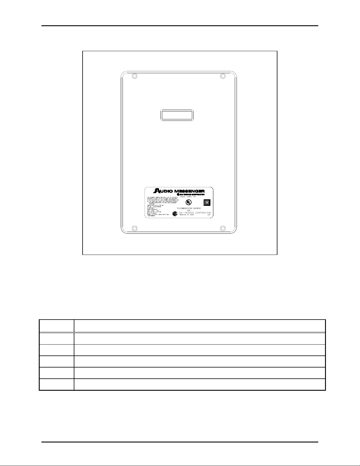
Figure 1. Wall-mount Audio Messenger Interface
The AMI is available in two enclosures, one for wall-mount installations and one for rack-mount
installations. Refer to the Model Chart below for the available models and options.
Table 1. Model Chart and Options
Model Description
10959-101 AMI Wall-Mount Tone/Speech Generator, 33-ohm Page/Party® Interface
10959-102 AMI Wall-Mount Tone/Speech Generator, 600-ohm Interface
10959-103 AMI Wall-Mount Tone/Speech Generator, Telephone Interface, 33-ohm Page/Party® Interfac e
10959-104 AMI Wall-Mount Tone/Speech Generato r, Teleph one Interface, 600-ohm Interface
10960-001 Zone Interface Module including the Amplifier Steering Module
The wall-mount AMI includes a front panel status display. The user controls, audio accessory jack, and
memory card access slot are all internal to the enclosure.
f:\standard ioms - current release\42004 instr. manuals\42004-398e.doc
10/09
Page 8

Pub. 42004-398E
ODEL 10959-10X WALL-MOUNT AUDIO MESSENGER INTERFACE PAGE 6 of 31
M
Specifications
Power Supply Requirements
Connection to a 12 to 24 V dc (UL-listed) Class 2 power source........................................ 1 amp minimum
Power consumed.............................................................................................................. 10 watts maximum
Mechanical
Enclosure material..................................................................High-impact, glass-reinforced polyester, gray
Mounting.......................................................................................Wall mounting; four 0.28 mounting holes
Connections........................................................................................Four drill spots for location of conduit
Dimensions ....................................................... 13.00 H × 9.25 W × 4.00 D inches; (330 × 235 × 102 mm)
Weight.................................................................................................................................... 5 lbs. (2.27 kg)
Environmental
Temperature range...................................................................................+32º F to +122º F (0º C to +50º C)
Approvals
Safety of Information Technology Equipment ......UL 60950, CAN/CSA-C22.2 No. 60950-00, IEC 60950
FCC Information
Complies with CFR47, Part 15...........................................................................................................Class A
FCC Registration Number ........................................................................................ US: ADGOT01B46055
Ringer Equivalence (REN)..................................................................................................................... 0.1B
Telephone Network Interface...........................................................Telephone Central Office Line or PBX,
(USOC) RJ11 jack, using 2-wire loop start (bridged ringing) circuit
IC Information (Canada)
IC Certification Number................................................................................................................ 82211853
Ringer Equivalence Number................................................................................................................... 0.1B
Connecting method..........................................................................Telephone Central Office Line or PBX,
(CA11A) using 2-wire loop start (bridged ringing) circuit
AMI Main PCBA
Speech capacity.........................................................Up to 500 minutes with 512 Mb CompactFlash
Audio output level...................................................................................Nominal 1 V
into 600-ohm load
RMS
®
card
Auxiliary outputs ...............................................................Sink 100 mA max. per output to circuit common
and pulled up to the power input voltage
Memory...........................................................................................................CompactFlash
®
memory card
AMI Termination PCBA
33-ohm page line.......................................................................................33 ohms nominal load impedance
Page line output level...................................................................................... Adjustable; 1.4 V
nominal
RMS
Telephone Interface Main PCBA
Inputs ..........................Telephone line audio from SPRLM-3 Module, below –40 dBm to –10 dBm typical
Audio from AMI Main PCBA—voice level, 1 V
Outputs.................................................................................................Audio to telephone line, 1 V
Audio to AMI PCBA, 1 V
f:\standard ioms - current release\42004 instr. manuals\42004-398e.doc
10/09
RMS
RMS
RMS
max.
max.
max.
Page 9

Pub. 42004-398E
ODEL 10959-10X WALL-MOUNT AUDIO MESSENGER INTERFACE PAGE 7 of 31
M
Controls......................................................................................................................S1: data address switch
R120: audio level from telephone line
R122: audio level to telephone line
Network signaling.......................................................................(via Registered SPRLM-3 Module) DTMF
Supervision ..................................... Telephone line battery wink or polarity reversal or audio silence timer
Minimum required loop current........................................................................................................... 25 mA
Registered Telephone Line Module (SPRLM-3 Module)
Trade name...............................SPRLM-3 Registered Line Module Equipment Type: Analog Line Module
Controls................................................................................................Access, Off-hook detect level jumper
Connections......................................................................................Telephone Line: E1-E2 screw terminals
Power and control: 9-pin female inline, for mating with
0.1 inch pitch × 0.025 inch square pin header
®
Page/Party
Interface
Page line..................................................................................................... 33-ohm nominal load impedance
Party line........................................................................................... 33-ohm nominal ac source impedance
Page line output level...................................................................................... Adjustable; 1.5 V
Inputs/outputs......................................................... Page line, 5 party lines, audio level 1.5 V
Audio to/from AGI Main and Page/Party
®
PCBA 1.0 V
nominal
RMS
maximum
RMS
maximum
RMS
Controls..........................................................................................................POT1: audio level to party line
POT2: audio level to page line
Installation
Power Disconnect. The power cord is the main power disconnect for all units.
Disjontion de l’alimentation. Le cordon d’alimentation est la disjonction d’alimentation
principale tous les appareils.
Para Desconectar la Alimentación: El cable de alimentación es el medio principal de
desconexión del equipo.
Netzanschluß. Wenn man das Netzkabel aus der Steckdose zieht, dann ist die
Spannungszuführung zum Gerät vollkommen unterbrochen.
CAUTION To reduce the risk of fire, use only No. 26 AWG or larger telecommunication
line cord.
ATTENTION Pour réduire le risque d’incendie, utiliser uniquement des conducteurs de
télécommunications 26 AWG ou de section supérieure.
PRECAUCIÓN Para aminorar la posibilidad de incendios, utilice solamente cable de
telecomunicaciones de calibre 26 (sistema AWG americano) o mayor.
VORSICHT Um die Brandgefahr zu verringern, verwenden Sie bitte nur Fernmeldekabel
der Stärke Nr. 26 AWG oder höher.
f:\standard ioms - current release\42004 instr. manuals\42004-398e.doc
10/09
Page 10
Pub. 42004-398E
ODEL 10959-10X WALL-MOUNT AUDIO MESSENGER INTERFACE PAGE 8 of 31
M
Mounting
1. Loosen the four screws on the front cover. Open the front cover of the enclosure to the left.
2. Remove the cable connections between the front panel and rear enclosure.
3. Pull on the left side of the enclosure until the hinge pins pull loose to separate the front and rear
sections. Set the front half of the enclosure aside.
4. Determine the conduit or cable gland location on the rear enclosure. Drill spots have been provided
on top and bottom for use with either a chassis punch or hole saw. Cut or punch the appropriate size
hole(s) in the enclosure.
5. Use Myers ST-4 (1.25 inches) Scru-Tite hubs or equivalent. Reducers must be used for smaller
conduit sizes to ensure proper contact with the supplied grounding plates. The hub(s) must be
connected to the conduit before being connected to the enclo sur e.
6. Each mounting hole in the enclosure is 0.280 inch in diameter. Secure the rear enclosure on the wall
with screws or appropriate fasteners.
7. Route the dc power, audio, input/output control, and phone line throug h the conduit and into the
enclosure allowing adequate cable length to access terminal blocks.
8. Re-install the hinged front cover and re-connect the cables to the front panel. Refer to the connector
matrix on page 29 to reconnect AMI internal components, if needed.
Wiring
WARNING
WARNING
Do not apply power until all the connections have been wired.
Connect only to a UL-listed Class 2 power source.
f:\standard ioms - current release\42004 instr. manuals\42004-398e.doc
10/09
Page 11
Pub. 42004-398E
ODEL 10959-10X WALL-MOUNT AUDIO MESSENGER INTERFACE PAGE 9 of 31
M
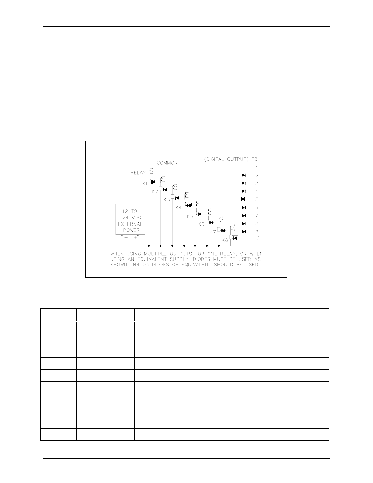
TB1 - Digital Output Connections
The TB1 connector (labeled DIGITAL OUTPUTS) provides eight digital (common ground) output
connections designed to drive externally-mounted relays or other indicating circuits. Each output can
sink up to 100 mA of the current. External circuitry (relays, indicators, etc.) must be powered from an
external power supply of the same voltage used to power the AMI (12 to 24 V dc). The ground (or dc
common) terminals of the external power supply must be tied to TB1-1 and/or TB1-10. Refer to the TB1
terminal block assignment chart and Figure 2 below.
If the application includes the Model 12584-001 I/O Control Module, please refer to Pub. 42004-359 for
installation, connection and specification details.
OTE: All outputs are programmed using AMI Configuration software. Each output must be
N
programmed before it can activate.
Figure 2. Typical digital output relay wiring
Table 2. Terminal Block 1 Assignments
Terminal Labeled Function Type
TB1-1
TB1-2
TB1-3
TB1-4
TB1-5
TB1-6
TB1-7
TB1-8
TB1-9
TB1-10
COMMON
AUX OUTPUT #1
AUX OUTPUT #2
AUX OUTPUT #3
AUX OUTPUT #4
AUX OUTPUT #5
AUX OUTPUT #6
AUX OUTPUT #7
AUX OUTPUT #8
COMMON
Ground DC power supply common
Output 1 Idle = +V dc, active (low) = sink100 mA maximum
Output 2 Idle = +V dc, active (low) = sink100 mA maximum
Output 3 Idle = +V dc, active (low) = sink100 mA maximum
Output 4 Idle = +V dc, active (low) = sink100 mA maximum
Output 5 Idle = +V dc, active (low) = sink100 mA maximum
Output 6 Idle = +V dc, active (low) = sink100 mA maximum
Output 7 Idle = +V dc, active (low) = sink100 mA maximum
Output 8 Idle = +V dc, active (low) = sink100 mA maximum
Ground DC power supply common
f:\standard ioms - current release\42004 instr. manuals\42004-398e.doc
10/09
Page 12

Pub. 42004-398E
ODEL 10959-10X WALL-MOUNT AUDIO MESSENGER INTERFACE PAGE 10 of 31
M
TB2 - Digital Input Connections
The TB2 connector (labeled DIGITAL INPUTS) provides connection for eight contact closure inputs for
activation AMI alarms or events. Switches or relay contact closures are used to activate the AMI inputs.
The input contacts may be any combination of momentary (pulsed) switches and maintained (latched)
switches. They can be either N.O. or N.C. dry contacts rated at 5 mA or better. Inputs 1 through 8 are
programmed using the AMI Configuration Tool software.
If the application includes the Model 12584-001 I/O Control Module, please refer to Pub. 42004-359 for
installation, connection and specification details.
OTE: For the inputs to operate reliably, the cable loop resistance connecting the relay/switch contact
N
closures cannot exceed 200 ohms. For example, using No. 24 AWG cable, the maximum cable length for
connection of the relay/switch contact closures cannot exceed 1,500 feet. Refer to the TB2 terminal block
assignment chart and Figure 3 below.
Figure 3. Typical input switch wiring
Table 3. Terminal Block 2 Assignments
Terminal Labeled Function Type of Source
TB2-1
TB2-2
TB2-3
TB2-4
TB2-5
TB2-6
TB2-7
TB2-8
TB2-9
TB2-10
COMMON
INPUT
INPUT
INPUT
INPUT
INPUT
INPUT
INPUT
INPUT
COMMON
Ground Ground reference for inputs 1 through 8
Input 1 Activates input #1 (as programmed)
#1
Input 2 Activates input #2 (as programmed)
#2
Input 3 Activates input #3 (as programmed)
#3
Input 4 Activates input #4 (as programmed)
#4
Input 5 Activates input #5 (as programmed)
#5
Input 6 Activates input #6 (as programmed)
#6
Input 7 Activates input #7 (as programmed)
#7
Input 8 Activates input #8 (as programmed)
#8
Ground Ground reference for inputs 1 through 8
f:\standard ioms - current release\42004 instr. manuals\42004-398e.doc
10/09
Page 13

Pub. 42004-398E
ODEL 10959-10X WALL-MOUNT AUDIO MESSENGER INTERFACE PAGE 11 of 31
M
TB3 - Audio Output and Data Connections
The TB3 connector (labeled AUDIO) provides connections for audio inputs and outputs, and for local
RS485 data connections. Data connections are used when the AMI alarms are being controlled remotely
from a CPU or when the Model 12584-001 I/O Control Module is used to expand the inputs and outputs
to 40 each. A 600-ohm balanced audio output is provided to drive a power amplifier. Refer to the TB3
terminal block assignment chart and Figure 4 below.
OTE: If only 600-ohm audio will be used, ensure that jumper P7 is installed in po sition 1-2 to properly
N
terminate the 33-ohm output. Refer to Table 8, 69517-202 PCBA Jumper Functions, on page 14.
Figure 4. Typical amplifier input wiring
Table 4. Terminal Block 3 Assignments
Terminal Labeled Description Function
TB3-1
LINE
-
Page (L1)
Audio output (line level) to public address amplifier.
TB3-2
TB3-3
TB3-4
TB3-5
TB3-6
TB3-7
TB3-8
TB3-9
TB3-10
LINE
L1
L2
L1
L2
POWER
DATA
DATA-
DATA+
+
GND
GND
Page (L2)
Audio 2 (L1)
Audio 2 (L2)
Audio 1 (L1)
Audio 1 (L2)
Refer to Figure 4.
No customer connections – used for internal
connections to Telephone Interface PCBA
No customer connections – used for internal
connection to Telephone Interface PCBA.
Power ground Power supply common
Data ground N/C
Data (-) To Model 12584-001 I/O Control Module (TB2-2)
Data (+) To Model 12584-001 I/O Control Module (TB2-1)
f:\standard ioms - current release\42004 instr. manuals\42004-398e.doc
10/09
Page 14

Pub. 42004-398E
ODEL 10959-10X WALL-MOUNT AUDIO MESSENGER INTERFACE PAGE 12 of 31
M
TB4 - Reboot and Fault Output
Reboot
The reboot terminals (TB4-5 and TB4-6) override and abort any activity in progress. To control the
reboot function, a user-supplied, remote, momentary, normally open (N.O.) switch contact closure must
be connected between TB4-5 and TB4-6 (or other GND return). Refer to the TB4 terminal block
assignment chart and Figure 5 below.
Fault Output
If the AMI processor is operating, the fault output is on (TB4-4 active low) and can be used to energize
external relays or indicating devices. If a fault is detected that prevents the AMI processor from
functioning, or if the CompactFlash
®
card is removed, or if communication is lost with one of the
auxiliary boards, the output is turned off (pulled high). Refer to Figure 6 and TB4 (SYSTEM) terminal
block assignments below, which provide the following external control functions:
OTE: For the inputs to operate reliably, the cable loop resistance connecting any relay/switch contact
N
closures cannot exceed 200 ohms. For example, using No. 24 AWG cable, the maximum cable length for
connection of the relay/switch contact closures cannot exceed 1,500 feet.
Figure 5. Typical reboot switch wiring
Figure 6. Typical fault configuration shown using
external relay with dry contact
f:\standard ioms - current release\42004 instr. manuals\42004-398e.doc
10/09
Page 15

Pub. 42004-398E
ODEL 10959-10X WALL-MOUNT AUDIO MESSENGER INTERFACE PAGE 13 of 31
M
Table 5. Terminal Block 4 Assignments
Terminal Labeled Description Function
TB4-1
TB4-2
TB4-3
TB4-4
GND
-
+
FLT
Data (Gnd)
Data (-)
No customer connections
Data (+)
Fault (output) If the AMI is operating normally, this output is active low
and can sink 100 mA maximum to external relay or
monitoring circuit. If fault is detected within the AMI, this
output switches off and stops current flow to the external
device. Refer to Figure 6 for typical connection.
TB4-5
REBOOT
System reboot When AMI is operating, this pin is 5 V dc. To reboot the
AMI, momentarily connect this pin to TB4-6.
Refer to Figure 5 for typical connection.
TB4-6
TB4-7
TB4-8
GND
.
Power ground Power supply common.
Relay (N.O.)
Relay (com)
Solid state relay closure. On resistance = 30 ohms
When AMI is playing a message, this contact is closed.
TB5 - Auxiliary Audio
The TB5 connector (labeled AUX) provides connections for the following auxiliary audio inputs and a 33ohm page line output. Jumper P7 can be used to provide 33-ohm termination for the page line if desired.
Refer to Table 8, 69517-202 PCBA Jumper Functions, on page 14.
Table 6. Terminal Block 5 Assignments
Terminal Labeled Description Function
TB5-1
TB5-2
TB5-3
IN
COM
Mic Input (hi)
Mic Input (low)
Ground Microphone cable shield termination.
Reserved for future connection for external noise-sensing
microphone.
TB5-4
TB5-5
TB5-6
L1
L2
Page L1
Page L2
Spare
Connects to the page line of the Page/Party
®
system
f:\standard ioms - current release\42004 instr. manuals\42004-398e.doc
10/09
Page 16

Pub. 42004-398E
ODEL 10959-10X WALL-MOUNT AUDIO MESSENGER INTERFACE PAGE 14 of 31
M
TB6 - Power Connections
The AMI requires a dc power supply. The dc power supply voltage must be between 12 and 24 V dc.
TB6 is used for power connections. Please refer to Figure 7 and Table 7 below.
Figure 7. Power connections at TB6
Table 7. Terminal Block 6 Assignments
Terminal Labeled
TB6-1
+
Description
Function
Power (+) 12 to 24 V dc power supply positive terminal
(Black wire with white stripe from power supply)
TB6-2
-
Power (-) 12 to 24 V dc power supply negative terminal
(Solid black wire from power supply)
TB6-3
Ground Earth ground
69517-202 Jumper Settings
Table 8. 69517-202 PCBA Jumper Functions
Jumper Output Position Function
1-2 600-ohm termination resistor connected P1 TB3-5, 6
Audio bus 1
2-3 Default - unterminated
1-2 600-ohm termination resistor connected P5 TB3-1, 2
600 ohms
2-3 Default - unterminated
1-2 600-ohm termination resistor connected P6 TB3-3, 4
Audio bus 2
2-3 Default - unterminated
1-2 33-ohm termination resistor connected P7 TB5-4, 5
33 ohms
2-3 Default - unterminated
1-2 33-ohm page output always active P9 TB5-4, 5
33 ohms
2-3 Default – 33-ohm page output active with audio
1-2 Supervision resistor network, 4.7k in series, 15k in parallel P11 TB4-7, 8
Audio
contact
f:\standard ioms - current release\42004 instr. manuals\42004-398e.doc
10/09
2-3 Default - unsupervised
Page 17

Pub. 42004-398E
ODEL 10959-10X WALL-MOUNT AUDIO MESSENGER INTERFACE PAGE 15 of 31
M
NOTES: P1, P5, P6, and P11 are for use with ADVANCE systems.
P9: Use the 33-ohm termination resistor only if there is not a termination resistor already on the page
line.
Figure 8. Jumper Locations on Termination PCBA
Telephone Line Connection
For AMI units equipped with a Telephone Interface board 69501-xxx (Models 10959-103 and 10959-
104), connections are made to a standard PBX analog station port, or directly to a central office (CO)
telephone line.
For Models 10959-103 and 109-104, the incoming telephone line must be connected to the tip (E1) and
ring (E2) of the Registered Line Module (SPRLM-3). A telephone cord with a modular RJ-11 plug is
provided.
N
OTE: The telephone interface requires a minimum loop current of 25 mA.
f:\standard ioms - current release\42004 instr. manuals\42004-398e.doc
10/09
Page 18

Pub. 42004-398E
ODEL 10959-10X WALL-MOUNT AUDIO MESSENGER INTERFACE PAGE 16 of 31
M
Page/Party® System Connections
NOTE: These connections apply to Models 10959-101 and 10959-103 only, and are only used when the
AMI is installed in a GAI-Tronics Page/Party
All connections are made to TB1 on the 69502-xxx Page/Party
®
system.
®
Interface PCBA. Refer to Figure 9 for
connection locations and to Figure 10 for the terminal block location. The connections to the page and
party audio lines of the system should be made to the nearest handset or speaker station in the Page/Party
system. For the Model 10959-101, only the page line is connected. See Figure 9.
For Model 10959-103, the page and five party lines can be connected. The party line associated with the
telephone interface is configured using the ACT software.
®
®
Figure 9. Page/Party
wiring diagram with Telephone Interface
Figure 10. 69502-xxx Page/Party
®
Interface PCBA
f:\standard ioms - current release\42004 instr. manuals\42004-398e.doc
10/09
Page 19

Pub. 42004-398E
ODEL 10959-10X WALL-MOUNT AUDIO MESSENGER INTERFACE PAGE 17 of 31
M
The Page/Party® Interface TB1 terminal block assignments are as follows:
Table 9. Page/Party
Terminal Description Function
TB1-1 Page (L1)
Connects to the page line of Page/Party
TB1-2 Page (L2)
TB1-3 Party 1 (L1)
Connects to party line 1 of the Page/Party
TB1-4 Party 1 (L2)
TB1-5 Party 2 (L1)
Connects to party line 2 of the Page/Party® system.
TB1-6 Party 2 (L2)
TB1-7 Party 3 (L1)
Connects to party line 3 of the Page/Party
TB1-8 Party 3 (L2)
TB1-9 Party 4 (L1)
Connects to party line 4 of the Page/Party
TB1-10 Party 4 (L2)
TB1-11 Party 5 (L1)
Connects to party line 5 of the Page/Party® system.
TB1-12 Party 5 (L2)
®
Interface Terminal Block 1
®
system.
®
system.
®
system.
®
system.
Resistive line balancing is required for the page line. If the AMI is installed in an existing or new
Page/Party
®
system with a Model 305-001 Line Balance, no additional line balancing is required.
However, if no resistive line balance exists, a 33-ohm resistor must be installed in parallel with the page
line.
®
The 69502-xxx Page/Party
party lines. If the AMI is installed in an existing or new Page/Party
Interface PCBA includes the 33-ohm resistive line balancing required for
®
system with a Model 305-001 Line
Balance for each connected party line, the corresponding 33-ohm resistors in the Model 305-001 must be
removed to maintain proper audio levels.
f:\standard ioms - current release\42004 instr. manuals\42004-398e.doc
10/09
Page 20

Pub. 42004-398E
ODEL 10959-10X WALL-MOUNT AUDIO MESSENGER INTERFACE PAGE 18 of 31
M
Setup
Preparation
When the AMI configuration is completed and the unit is ready for testing, please ensure the AMI is
installed and connections are made consistent with the Installation section on page 7. Please verify the
following:
• DC power connected and polarity is correct
• Inputs are connected
• Outputs are connected
• Phone line is connected (if applicable)
• Page and party lines are connected (if applicable)
• Paging amplifier is connected (if using 600-ohm output)
• Resistive line balance is installed to support the Page line.
• Existing party line resistive line balancing is disconnected.
f:\standard ioms - current release\42004 instr. manuals\42004-398e.doc
10/09
Page 21

Pub. 42004-398E
ODEL 10959-10X WALL-MOUNT AUDIO MESSENGER INTERFACE PAGE 19 of 31
M
When power is applied to the AMI and the power up sequence begins, the LCD display begins cycling
through the following messages:
• AMI x.x.x (x.x.x AMI Main board firmware version)
• Boot DSP
• CompactFlash
®
detected (CompactFlash® card detected)
• EEPROM xxx (xxx AMI Main board EPROM format)
• DSP VER:x.x.x
• Flash OK (Successfully read whole CompactFlash
®
card)
• Progress bar
CFG Loading (Configuration loading)
• Configuration Version
• Configuration Date and Time
• Configuration file name (i.e., AMI factory default)
• Time and Page Symbol (page symbol is a speaker)
HIO board firmware version (if HIO controller board installed)
• Time and Page Symbol (page symbol is a speaker)
ASM board firmware version (if ASM board installed)
®
• Time, Party Line and Page Symbol (default party line is 1, if Page/Party
Page/Party
®
board firmware version (if Page/Party® board installed)
board installed)
• Time, Party Line and Page Symbol
AMI Main board firmware version
• ## Time, Party Line and Page Symbol
Telephone Interface Mode (default is Page/Party
®
mode)
• Time, Party Line and Page Symbol
Telephone Interface Board firmware version (if Telephone Interface Board installed)
• ## Time, Party Line and Page Symbol (default is no greeting)
Telephone Interface Greeting file name (this prompt is not displayed.)
• Time, Party Line and Page Symbol
AMI ready (System is now running, displayed for two seconds only)
• Time, Party Line and Page Symbol
Date (date will display on the start of the next minute)
## Will only be displayed if a Telephone Interface board option is installed
Setting the Date and Time
To set the time and date, please refer to LCD Display and Push-button Operation on page 21.
Initiating a Page
Using one of the connected inputs or the AMI push buttons, initiate a page. After the page is initiated,
verify the proper message is played to the proper audio system (i.e., Page/Party
combination is asserted. If using the AMI Factory Default configuration, a message and corresponding
output are assigned to each of the first seven inputs.
f:\standard ioms - current release\42004 instr. manuals\42004-398e.doc
10/09
®
) and the proper output
Page 22

Pub. 42004-398E
ODEL 10959-10X WALL-MOUNT AUDIO MESSENGER INTERFACE PAGE 20 of 31
M
Verifying Telephone-to-Page/Party® Operation
If you have both the Telephone Interface and the Page/Party® boards installed and are planning to use the
telephone-to-party line feature, the Page/Party
Page/Party
®
board must be balanced. Use the following procedure to balance the Page/Party® board:
• Move switch (S1) on the Page/Party
• Press the reset button on the Page/Party
The Data LED (LED1) stops flashing and the party line LEDs (LEDs 2 through 6) lights one at a time
with LED 7 flashing once for each party line. When the Page/Party
®
system page and party lines must be connected and the
®
board to position “C”.
®
board (PB1).
®
board has completed the line
balancing, LED 6 and LED 7 will be on.
®
• Move switch (S1) on the Page/Party
• Press the reset button on the Page/Party
board to position “3”.
®
board (PB1).
The Data LED starts flashing again and LED 6 goes off. Party line 1 LED (LED 2) will come on.
®
Figure 11. 69502-xxx Page/Party
After the telephone and Page/Party
®
system interconnections have been made, call the AMI. The AMI
Interface PCBA
auto answers after two rings. Using the AMI factory default configuration, a high-low tone is played to
let you know to start making your page. When the party line is picked up, a dual tone is played to let you
know to start your party conversation.
There are three potentiometers allowing minor adjustments to the audio levels for the two-way phone-toparty line audio. The potentiometers are factory set and should not need to be changed. If the audio
levels are not sufficient for your applicati on, we suggest contacting the GAI-Tronics Service Department.
The service technicians will guide you through adjusting the following audio levels.
®
• POT1 on Page/Party
board – adjusts level of audio to the party lines.
• R120 on the Telephone Interface board – adjusts level of audio from the phone line.
• R122 on the Telephone Interface board – adjusts level of audio to the phone line.
• POT2 on the Page/Party
f:\standard ioms - current release\42004 instr. manuals\42004-398e.doc
10/09
®
board - adjusts level of audio to the page line.
Page 23

Pub. 42004-398E
ODEL 10959-10X WALL-MOUNT AUDIO MESSENGER INTERFACE PAGE 21 of 31
M
Operation
LCD Display and Push-button Operation
The front panel of the AMI Unit contains a two-line LCD display that reflects the current operational
status of the unit. During normal operation, the display shows the current time, default page line
selection, and the current date. Time is displayed in the HH:MM format. A flashing “:” between the hour
and minute display indicates the unit is active and running. The date displays in the MM-DD-YYYY
format. The LCD uses various symbols to visually indicate AMI activity. They are:
• VU Meter – indicates relative volume of a playing message.
• Progress Bar – indicates remaining time for the party line connection timeout (configured in ACT).
• Telephone Handset – indicates the AMI unit is being accessed via a telephone connection, for a page
or for a telephone-to-party conversation.
• Microphone – indicates a page from the auxiliary jack.
• Speaker – indicates a page is being sent to the page output of the AMI.
• Right/Left Arrow Indicators – indicate transmit and receive activity on the auxiliary jack.
• Text Display (scrolling) – displays current system status, such as the name of the current message
playing, telephone connection status, paging status, and party connection status.
• Rotating Slash – when visible, indicates the AMI has a lower priority message pending, ready to be
played.
In addition to the display providing system status, control buttons provide a way to access the AMI menu
to control various functions of the system. The wall-mount units include the control buttons inside of the
enclosure. The functions of the four push buttons are as follows:
Push button PB1 = Scroll UP function
Push button PB3 = Scroll DOWN function
Push button PB3 = SELECT function
Push button PB4 = ENTER function
Pressing the ENTER button puts the AMI into the program selection mode. The SELECT button scrolls
through all available menu options. The buttons marked with up and down arrows allow you to scroll to
select settings.
f:\standard ioms - current release\42004 instr. manuals\42004-398e.doc
10/09
Page 24

Pub. 42004-398E
ODEL 10959-10X WALL-MOUNT AUDIO MESSENGER INTERFACE PAGE 22 of 31
M
These options are available via the AMI menu system:
Cancel Outputs - This menu item turns off the outputs. This button sequence is used:
<ENTER> to enter the menu system
<SELECT> to scroll the menu to the Cancel Outputs item
<ENTER> to select the Ca ncel Outputs item and turn off the outputs.
Time - This menu selection is used to set the system time for the AMI. This button sequence allows the
user to set the desired time:
<ENTER> to enter the menu system
<SELECT> to scroll the menu to the Time: item
<ENTER> to select the Time: item
<ENTER> to confirm selection
↑ to select desired hour value
↓,
<SELECT> to scroll to minute value
↑ to select desired m inute value
↓,
<ENTER> to accept the new time setting.
Date - This menu selection is used to set the date for the AMI. This button sequence allows the user to
set the current date:
<ENTER> to enter the menu system
<SELECT> to scroll the menu to the Date: item
<ENTER> to select the Date: item
<ENTER> to confirm selection
↑ to select the desired day value
↓,
<SELECT> to scroll to the month value
↑ to select desired the month value
↓,
<SELECT> to scroll to the year value
↓,
↑ to select desired the year value
<ENTER> to accept the new date setting.
f:\standard ioms - current release\42004 instr. manuals\42004-398e.doc
10/09
Page 25

Pub. 42004-398E
ODEL 10959-10X WALL-MOUNT AUDIO MESSENGER INTERFACE PAGE 23 of 31
M
Play - This menu item is selected to play a specific message. Messages are grouped by priority
(1 through 7). This button sequence allows the user to select a message to be played from a specific
priority group:
<ENTER>
<SELECT>
<ENTER>
<SELECT>
<ENTER>
<SELECT>
<ENTER>
to enter the menu system
to scroll the menu to the Play: item
to select the Play: item
to scroll to the desired priority group
to select messages associated with the priority group
to scroll available messages within the group
to play the selected message.
Stop - This function halts the currently playing message. This button sequence is used:
<ENTER>
<SELECT>
<ENTER>
<ENTER>
to enter the menu system
to scroll the menu to the Stop: item
to select the Stop: item
to confirm the selection
P/P 50KHz VLC Tone – This menu item is used to enable or disable a sustained 50 kHz VLC tone on
®
the Page/Party
<ENTER>
<SELECT>
board
to enter the menu system
to scroll the menu to the PP 50KHz VLC Tone: item
<ENTER>
to select the PP 50KHz VLC Tone: item. Toggle 50KHz VLC Tone scrolls across the
display.
<SELECT>
<ENTER>
to scroll to select Start PP 50KHz VLC Tone or Cancel 50KHz VLC Tone
to select the desired 50 kHz VLC tone action. The display shows Starting 50KHz VLC
Tone or Canceling 50KHz VLC Tone, depending upon the selected action.
Phone Mode – This menu item is used to select Day or Night mode operation for the AMI.
<ENTER>
<SELECT>
<ENTER>
to enter the menu system
to scroll the menu to the Phone Mode: item
to select the Phone Mode: item, Toggle Phone Mode will scroll across the display
<SELECT> to scroll to select Night Mode Phone Mode or Day Mode Phone Mode
<ENTER> to select the desired mode. The display will show Phone Mode Switched
f:\standard ioms - current release\42004 instr. manuals\42004-398e.doc
10/09
Page 26

Pub. 42004-398E
ODEL 10959-10X WALL-MOUNT AUDIO MESSENGER INTERFACE PAGE 24 of 31
M
Firmware Update – This menu item provides the means for updating the firmware of the AMI main
board. This button sequence is used:
<ENTER>
<SELECT>
<ENTER>
<ENTER>
to enter the menu system
to scroll the menu to the Firmware Update: item
to select the Firmware Update: item
to confirm the selection.
The display will show updating, followed by complete when the firmware update has been
successfully completed. The unit will then reboot, using the updated firmware.
Reset AMI - This menu item reboots the AMI main board. This button sequence allows the user to
reboot the system:
<ENTER>
<SELECT>
<ENTER>
<ENTER>
to enter the menu system
to scroll the menu to the System Reboot: item
to select the System Reboot: item
to confirm the selection.
Return - Selecting this menu item returns the system to normal operation mode.
<ENTER> to enter the menu system
<SELECT> to scroll the menu to the Return item
<ENTER> to select the Return menu item and return to normal operating mode.
f:\standard ioms - current release\42004 instr. manuals\42004-398e.doc
10/09
Page 27

Pub. 42004-398E
ODEL 10959-10X WALL-MOUNT AUDIO MESSENGER INTERFACE PAGE 25 of 31
M
Working with CompactFlash®
CompactFlash® Memory Card In stallation
The CompactFlash® memory card stores the system configuration, speech messages, and alarm tones.
When the memory card is being installed, complete the following instructions:
Insert the memory card into the card reader on the 69449-xxx AMI Main Board. Ensure the label on the
memory card faces up and slide the memory card in until it is fully seated in the slot. When seated
properly, the card protrudes approximately ¼ inch.
OTE: The memory card and its socket are keyed for proper insertion – do not force the card into the
N
socket.
Follow the instructions on page 24 to reboot the system so the memory card will be read by the AMI unit.
Saving Configurations to a CompactFlash® Card
Custom configurations are created using the ACT software. After a custom configuration is created, it
must be compiled to the local hard drive (typically in the “C:\Program Files\AMI Configuration
Tool\AMI Configs” folder). After the configuration is compiled to the hard drive, it must be moved or
copied to the CompactFlash
N
OTE: Custom configurations cannot be compiled directly to a CompactFlash
®
card using Windows Explorer.
®
card.
CompactFlash
®
Card Formatting
All new CompactFlash® memory cards must be formatted specifically for use with the AMI. Formatting
is accomplished using the following DOS format command from the Windows command prompt:
Format <drive>: /a:16K
®
where <drive> is the drive letter of the PC’s CompactFlash
OTE: Successful formatting of the CompactFlash
N
®
card can be performed only on Windows 2000 and
reader/writer.
Windows XP workstations.
f:\standard ioms - current release\42004 instr. manuals\42004-398e.doc
10/09
Page 28

Pub. 42004-398E
ODEL 10959-10X WALL-MOUNT AUDIO MESSENGER INTERFACE PAGE 26 of 31
M
Overview of the AMI Configuration Tool (ACT)
When programmed, the CompactFlash® memory card provides the custom configuration for the AMI.
The CompactFlash
provided with the unit. The application must be installed on a Windows PC (Windows 98/XP/2000)
equipped with a USB-connected reader/writer capable of programming CompactFlash
®
card is programmed using the AMI Configuration Tool software application
®
memory cards.
Please refer to the online help for specific instructions. Some of the configurable parameters are:
®
1. Fragments: All tones and voice messages are digitally recorded and stored on the CompactFlash
card as MP3 files.
2. Messages: Each message is a collection of fragments. The content of each message must be defined
by selecting the fragment(s) to be incorporated into the message. Other message parameters include:
• Message title
• Priority
• Volume
• Play mode and repeat interval
• Activation of the 50 kHz VLC tone
3. Inputs: Each input circuit must be enabled or disabled. If enabled, it must be programmed with
several parameters such as:
• Title containing a brief text description of the input and its use
• The type of switch contact being used to activate the input (norm ally open, closed )
• The action of the switch (maintained, momentary, toggle on/off)
• Function of the input (activate a message, reboot, mute, etc.)
4. Output: Each output circuit must be enabled or disabled. If enabled, it must be programmed with
several parameters such as:
• Title, which contains a brief text description of the output describing its use
• Mode of operation when active (maintained, flash, momentary, flicker)
• Activation assignment from an input or scheduled event
5. Telephone Interface: If using the telephone interface, several parameters must be set:
• The number of rings before answer
• Paging mode (live or recorded)
• Page delay, if recorded
• Maximum page duration
• Selection of a greeting message to be played to the caller
• Selection of a pre-announcement tone to be played to the PA system
6. Event Scheduling: Using the event-scheduling feature, messages can be set up to automatically play
at certain dates and times. When scheduling events several parameters must be set:
• Start and stop times
• Start and stop dates
• Event duration and intervals
7. Zone Groups: Zone groups are configured with a unique description, and assigned any combination
of the eight available output zones.
f:\standard ioms - current release\42004 instr. manuals\42004-398e.doc
10/09
Page 29

Pub. 42004-398E
ODEL 10959-10X WALL-MOUNT AUDIO MESSENGER INTERFACE PAGE 27 of 31
M
Remote Commands
After a call has been connected to the AMI, the caller can enter a valid remote command using the DTMF
keypad of the telephone. During the greeting message, the caller must enter a DTMF “*” to access
remote control. The greeting message will be halted, and two consecutive beeps will sound, indicating
the unit has entered remote control mode.
After entering remote control mode, callers can direct a page to a specific zone group by entering a
DTMF “#”, followed by the two-digit zone group number. Valid zone group numbers are 01–60.
Entering #00 selects the all-call feature.
Additional remote commands are available for wall-mount AMI units equipped with the 33-ohm
Page/Party
®
Interface. Callers can choose the party line that will be connected for a subsequent telephone
conversation. After entering remote control mode, the caller enters a DTMF “*”, followed by the singledigit party line (1–5). The AMI will continue with live page or recorded paging, depending upon the
configured page mode. When the page is answered, the caller is connected to the selected party line.
The Off-hook Timeout setting for the Telephone Interface in the ACT tool limits the duration of a party
conversation. Approximately 20 seconds prior to the configured timeout expiration, the AMI will emit a
warning tone, indicating that the connected call is about to be terminated. If the caller enters the DTMF
“*” key, the AMI extends the conversation by the length of time defined by the Off-hook Timeout
parameter. Two consecutive beeps are sounded when the AMI timeout has been successfully extended.
While a caller is waiting for the paged party to respond, entering the DMTF “#” causes the AMI to restart
paging. Callers can either reissue a page for the original party, or make a page for another party.
OTE: The caller does not access remote control mode to extend the connected party conversation or to
N
reissue a page.
f:\standard ioms - current release\42004 instr. manuals\42004-398e.doc
10/09
Page 30

Pub. 42004-398E
ODEL 10959-10X WALL-MOUNT AUDIO MESSENGER INTERFACE PAGE 28 of 31
M
Maintenance
If your AMI Interface requires service, contact your GAI-Tronics Regional Service Center for a return
authorization number (RA#). Equipment should be shipped prepaid to GAI-Tronics with a return
authorization number and a purchase order number. If the equipment is under warranty, repairs will be
made without charge. Please include a written explanation of all defects to assist our technicians in their
troubleshooting efforts.
Call 800-492-1212 inside the USA or 610-777-1374 outside the USA for help identifying the Regional
Service Center closest to you.
Description of Major Components
Internal Components
The AMI contains the PCBAs as listed below. Refer to Figure 12 and Figure 13 for mounting locations.
69449-xxx AMI Main Board contains the CompactFlash
buttons, and the audio accessory jack.
69517-xxx Termination PCBA contains six plug-in connectors accessible through the rear panel, and an
internal power terminal strip.
®
memory card reader, the four user push
69501-xxx Telephone Interface (Models 10959-103 and -104 only) provides telephone callers several
methods of access to the communications and alarm system.
69404-xxx Registered Line Module (SPRLM-3) (Models 10959-103 and -104 only) and contains an
interface to either a PBX or public switched telephone network and is used in conjunction with the
Telephone Interface.
®
69502-xxx Page/Party
GAI-Tronics Page/Party
Interface (Models 10959-101 and –103 only) contains an interface to the
®
system.
Figure 12. Inside Enclosure Front Cover
f:\standard ioms - current release\42004 instr. manuals\42004-398e.doc
10/09
Page 31

Pub. 42004-398E
ODEL 10959-10X WALL-MOUNT AUDIO MESSENGER INTERFACE PAGE 29 of 31
M
Figure 13. Rear Enclosure – Location of PCBAs
Internal Cable Connections
The following is a matrix showing the connections for the AMI internal components:
Table 10. AMI Internal Component Connection Matrix
PCBA/Component Connector Matrix
AMI Main PCBA
AMI Telephone Main Module
Page/Party® Interface PCBA
Display Module
AMI Termination PCBA
P501 P502 P3 P4 P70 P8 P10
P4
P4
P3
P5
P8 *P1
CABLE
P10
*NOTE: P1 cable/connector is not keyed. Please ensure the red striped wire in the ribbon cable is
adjacent to pin 1 of the ribbon cable socket.
f:\standard ioms - current release\42004 instr. manuals\42004-398e.doc
10/09
Page 32

Pub. 42004-398E
ODEL 10959-10X WALL-MOUNT AUDIO MESSENGER INTERFACE PAGE 30 of 31
M
External Components
The AMI front panel contains an LCD display. The memory card port, auxiliary jack used for a desk mic,
and four user control buttons are located on the 69449-xxx AMI Main PCBA inside the enclosure.
↓ ↑
SELECT ENTER
The four buttons are used to access the AMI menu and to scroll through and select the system options.
Refer to the Operation section on page 21 for further information.
CompactFlash
®
Card Slot
The CompactFlash® memory card contains the system configuration, pre-recorded speech messages, and
pre-defined alarm tones for the AMI. The memory card is programmed using the GAI-Tronics AMI
Configuration Tool application. A programmed memory card must remain in the AMI memory card slot
during operation. See Working with CompactFlash
LCD Display
®
on page 25.
The LCD display on the front panel indicates the current day and time, along with the AMI status. Please
refer to the Power Up section on page 19 and the LCD Display and Push-button Operation section on
page 21 for details regarding display messages.
Replacement Parts
Table 11.
Model Number Description
69517-202 Termination PCBA
69501-101 Telephone Interface PCBA
69404-002 Register Line Module PCBA (SPRLM-3)
69502-201 Page/Party® Interface PCBA
49100-007 CompactFlash® Card (Blank)
Confidential ity Notice
This manual is provided solely as an operational, installation, and maintenance guide and contains
sensitive business and technical information that is confidential and proprietary to GAI-Tronics.
GAI-Tronics retains all intellectual property and other rights in or to the information contained herein, and
such information may only be used in connection with the operation of your GAI-Tronics product or
system. This manual may not be disclosed in any form, in whole or in part, directly or indirectly, to any
third party.
f:\standard ioms - current release\42004 instr. manuals\42004-398e.doc
10/09
Page 33

Pub. 42004-398E
ODEL 10959-10X WALL-MOUNT AUDIO MESSENGER INTERFACE PAGE 31 of 31
M
User Instructions (USA)
This equipment complies with Part 68 of the FCC rules and the requirements adopted by the ACTA. On this
equipment is a label that contains, among other information, a product identifier in the format
US:AAAEQ##TXXXX. If requested, this number must be provided to the telephone company.
A plug and jack used to connect this equipment to the premises wiring and telephone network must comply with the
applicable FCC Part 68 rules and requirements adopted by the ACTA. A compliant telephone cord and modular
plug is provided with this product. It is designed to be connected to a compatible modular jack that is also
compliant. See installation instructions for details.
The REN is used to determine the number of devices that may be connected to a telephone line. Excessive RENs on
the telephone line may result in the devices not ringing in response to an incoming call. In most but not all areas, the
sum of the RENs should not exceed five (5.0). To be certain of the number of devices that may be connected to a
line, as determined by the total RENs, contact the local telephone company. For products approved after July 23,
2001, the REN for this product is part of the product identifier that has the format US:AAAEQ##TXXXX. The
digits represented by ## are the REN without a decimal point (e.g., 03 is an REN of 0.3). For earlier products, the
REN is separately shown on the label.
If this equipment [GAI-Tronics telephone] causes harm to the telephone network, the telephone company will notify
you in advance that temporary discontinuance of service may be required. But if advance notice isn’t practical, the
telephone company will notify the customer as soon as possible. Also, you will be advised of your right to file a
complaint with the FCC if you believe it is necessar y.
The telephone company may make changes in its facilities, equipment, operations, or pro cedures that could affect
the operation of the equipment. If this happens the telephone company will provide advance notice in order for you
to make necessary modifications to maintain uninterrupted service.
If trouble is experienced with this equipment [GAI-Tronics telephone], for repair or warranty information, please
contact GAI-Tronics Corporation at 800-492-1212 or www.gai-tronics.com. If the equipment is causing harm to the
telephone network, the telephone company may request that you disconnect the equipment until the problem is
resolved.
Connection to party line service is subject to state tariffs. Contact the state public utility commission, public service
commission or corporation commission for information.
This equipment uses a telephone handset and it is hearing aid compatible.
User Instructions (Canada) CP -01, Issue 8, Part I: Section 14.1
NOTICE: The Industry Canada label identifies certified equipment. This certification means that the equip ment
meets certain telecommunications network protective, operational and safety requirements as prescribed in the
appropriate Terminal Equipment Technical Requirements document (s). The Department does not guarantee the
equipment will operate to the user's satisfaction. Before installing this equipment, users should ensure that it is
permissible to be connected to the facilities of the local telecommunications compan y. The equipment must also be
installed using an acceptable method of connection. The customer should be aware that compliance with the above
conditions may not prevent degradation of service in some situations. Rep airs to certified equipment should be
coordinated by a representative designated by the supplier. Any repairs or alterations made by the user to this
equipment, or equipment malfunctions, may gi ve the telecommunications company cause to request the user to
disconnect the equipment. Users should ensure for their own protection that the electrical ground connections of the
power utility, telephone lines and internal metallic water pipe system, if present, are connected together. This
precaution may be particularly important in rural areas.
CAUTION
Users should not attempt to make such connections themselves, but should contact the appropriate electric
inspection authority, or electrician, as appropriate.
CP-01, Issue 8, Part I: Section 1 4.2
NOTICE: The Ringer Equivalence Number (REN) assigned to each terminal device provides an indication of the
maximum number of terminals allowed to be connected to a telephone interface. The termination on an interface
may consist of any combination of devices subject only to the requirement that the sum of the Ringer Equivalence
Numbers of all the devices does not exceed 5.
f:\standard ioms - current release\42004 instr. manuals\42004-398e.doc
10/09
Page 34

Warranty
Equipment. GAI-Tronics warrants for a period of one (1) year from the date of shipment, that any
GAI-Tronics equipment supplied hereunder shall be free of defects in material and workmanship, shall
comply with the then-current product specifications and product literature, and if applicable, shall be fit
for the purpose specified in the agreed-upon quotation or proposal document. If (a) Seller’s goods prove
to be defective in workmanship and/or material under normal and proper usage, or unfit for the purpose
specified and agreed upon, and (b) Buyer’s claim is made within the warranty period set forth above,
Buyer may return such goods to GAI-Tronics’ nearest depot repair facility, freight prepaid, at which time
they will be repaired or replaced, at Seller’s option, without charge to Buyer. Repair or replacement shall
be Buyer’s sole and exclusive remedy. The warranty period on any repaired or replacement equipment
shall be the greater of the ninety (90) day repair warranty or one (1) year from the date the original
equipment was shipped. In no event shall GAI-Tronics warranty obligations with respect to equipment
exceed 100% of the total cost of the equipment supplied hereunder. Buyer may also be entitled to the
manufacturer’s warranty on any third-party goods supplied by GAI-Tronics hereunder. The applicability
of any such third-party warranty will be determined by GAI-Tronics.
Services. Any services GAI-Tronics provides hereunder, whether directly or through subcontractors,
shall be performed in accordance with the standard of care with which such services are normally
provided in the industry. If the services fail to meet the applicable industry standard, GAI-Tronics will
re-perform such services at no cost to buyer to correct said deficiency to Company's satisfaction provided
any and all issues are identified prior to the demobilization of the Contractor’s personnel from the work
site. Re-performance of services shall be Buyer’s sole and exclusive remedy, and in no event shall GAITronics warranty obligations with respect to services exceed 100% of the total cost of the services
provided hereunder.
Warranty Periods. Every claim by Buyer alleging a defect in the goods and/or services provided
hereunder shall be deemed waived unless such claim is made in writing within the applicable warranty
periods as set forth above. Provided, however, that if the defect complained of is latent and not
discoverable within the above warranty periods, every claim arising on account of such latent defect shall
be deemed waived unless it is made in writing within a reasonable time after such latent defect is or
should have been discovered by Buyer.
Limitations / Exclusions. The warranties herein shall not apply to, and GAI-Tronics shall not be
responsible for, any damage to the goods or failure of the services supplied hereunder, to the extent
caused by Buyer’s neglect, failure to follow operational and maintenance procedures provided with the
equipment, or the use of technicians not specifically authorized by GAI-Tronics to maintain or service the
equipment. THE WARRANTIES AND REMEDIES CONTAINED HEREIN ARE IN LIEU OF AND
EXCLUDE ALL OTHER WARRANTIES AND REMEDIES, WHETHER EXPRESS OR IMPLIED BY
OPERATION OF LAW OR OTHERWISE, INCLUDING ANY WARRANTIES OF
MERCHANTABILITY OR FITNESS FOR A PARTICULAR PURPOSE.
Return Policy
If the equipment requires service, contact your Regional Service Center for a return authorization number
(RA#). Equipment should be shipped prepaid to GAI-Tronics with a return authorization number and a
purchase order number. If the equipment is under warranty, repairs or a replacement will be made in
accordance with the warranty policy set forth above. Please include a written explanation of all defects to
assist our technicians in their troubleshooting efforts.
Call 800-492-1212 (inside the USA) or 610-777-1374 (outside the USA) for help identifying the
Regional Service Center closest to you.
(Rev. 10/06)
 Loading...