

Page 1

Pub. 42004-222D
GAI-TRONICS® CORPORATION
A HUBBELL COMPANY
Model 10468-002
Centra-Page System Central Cabinet
Confidential ity Notice
This manual is provided solely as an operational, installation, and maintenance guide and contains
sensitive business and technical information that is confidential and proprietary to GAI-Tronics. GAITronics retains all intellectual property and other rights in or to the information contained herein, and
such information may only be used in connection with the operation of your GAI-Tronics product or
system. This manual may not be disclosed in any form, in whole or in part, directly or indirectly, to any
third party.
Introduction
The GAI-Tronics Centra-Page System provides dependable paging and party line communications for
rugged and hazardous industrial facilities. It features centrally located electronics providing
environmental protection and unitized amplification for easy maintenance.
The Model 10468-002 Central Cabinet, a central component of a Centra-Page System, is designed to
house up to three Model 10461-002 Card Racks. A Model 10959-208 Audio Messenger Interface (AMI)
and a Model 10961-101 AMI Centra-Page Interface can also be added. Each of the three card racks can
support up to 10 line cards, and each line card supports one station. For ease of wiring, the central cabinet
offers terminal blocks for power and for remote connection of alarm and interface activation switches.
General Information
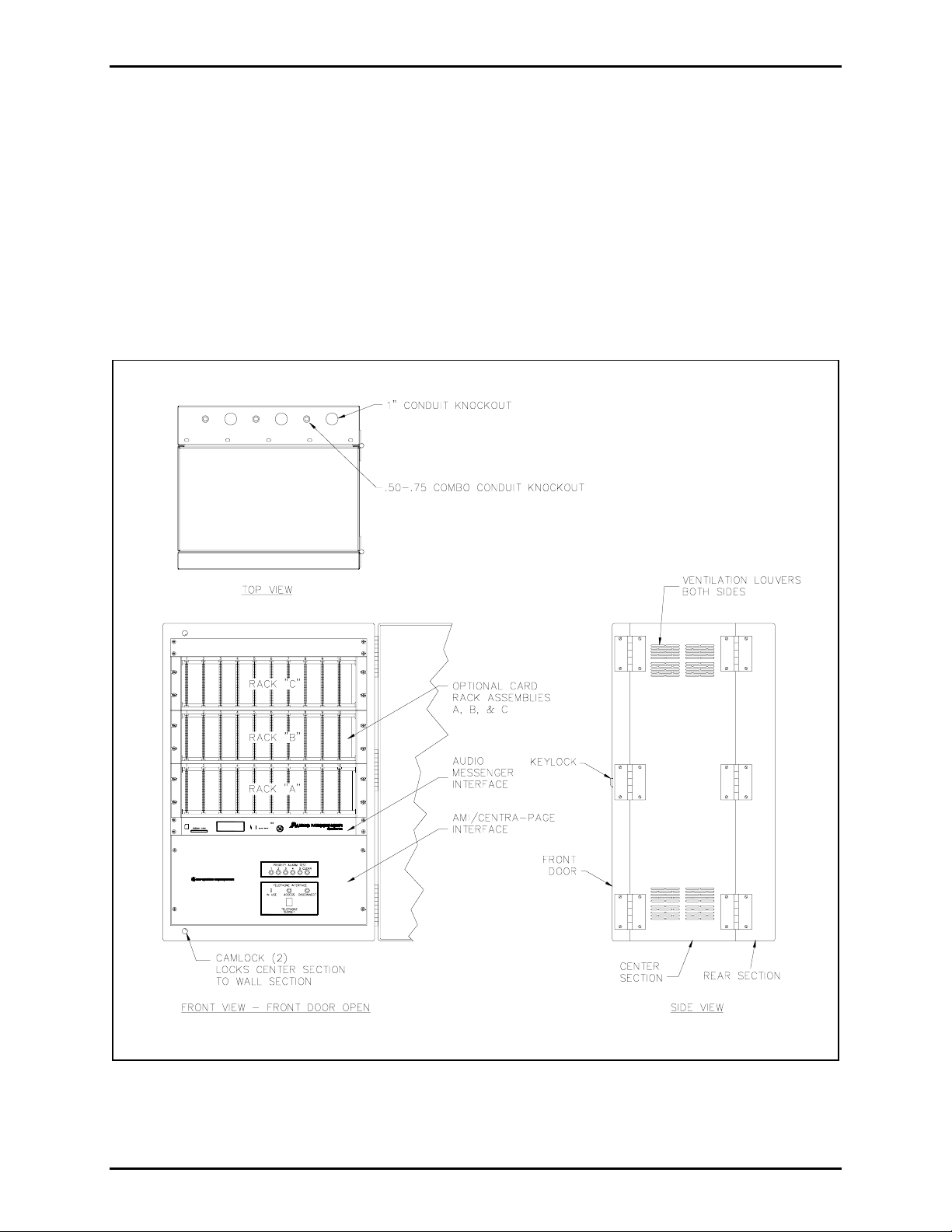
The Model 10468-002 Central Cabinet is a double-hinged, three-section, wall-mounted cabinet measuring
20.625 W × 18.5 D × 31 H inches. Use the supplied key to open the lockable front door and expose the
front of the center section.
The center section contains the card rack assemblies and has space for an optional Model 10959-208 AMI
and a Model 10961-101 AMI Centra-Page Interface. Swing the hinged center section open for easy
access to the rear of these components, cable connections, and individual volume adjustments.
See Figure 3 for the dimensions of the cabinet mounting holes located in the rear section. Ensure that the
mounting structure selected is sufficient to support the 165 lbs. (74.8 kg) weight of the fully equipped
cabinet. The rear section contains the term inal block s for the ind iv idual stat ion fi e ld wiring.
The cabinet is designed for input and output cables to enter at the top and bottom of the rear section. The
top and bottom each contain six knockouts for cable glands.
GAI-Tronics Corporation 400 E. Wyomissing Ave. Mohnton, PA 19540 USA
610-777-1374 800-492-1212 Fax: 610-796-5954
V
ISIT WWW.GAI-TRONICS.COM FOR PRODUCT LITERATURE AND MANUALS
Page 2

Pub. 42004-222D
Model 10468-002 Centra-Page System Central Cabinet Page: 2 of 8
Hazardous Areas
The Model 10468-002 Central Cabinet must
be mounted in a non-hazardous area, although other portions
of the Centra-Page system may be located in Div. I or Div. II hazardous areas if appropriate wiring
configurations and barriers are used. Refer to Pub. 42004-356, Control Drawing 72979, for proper
installation of stations for intrinsically safe operation in Class I, Div. I, Group C and D hazardous areas.
A typical Centra-Page System with components in both hazardous and non-hazardous areas is shown in
Figure 1.
Figure 1. Typical Centra-Page System Diagram
f:\standard ioms - current release\42004 instr. manuals\42004-222d.doc
02/10
Page 3
Pub. 42004-222D
Model 10468-002 Centra-Page System Central Cabinet Page: 3 of 8
Installation
Install the Model 10468-002 Central Cabinet as follows:
1. Carefully unpack and identify the various components. A parts envelope is included containing
screws and washers for mounting cabinet components. Two front door keys are packaged separately.
2. Determine which of cabling knockouts will be used and remove them before mounting the cabinet.
Refer to Figure 2.
3. Mount the cabinet to the wall using the mounting holes in the rear section. A fully-equipped cabinet
weighs approximately 165 lbs. (74.8 kg) and must be mounted accordingly.
Figure 2. Model 10468-002 Centra-Page Central Cabinet - outline
(shown fully-loaded for clarity)
f:\standard ioms - current release\42004 instr. manuals\42004-222d.doc
02/10
Page 4

Pub. 42004-222D
Model 10468-002 Centra-Page System Central Cabinet Page: 4 of 8
4. The standard cabinet is factory assembled and pre-wired. Wiring for power must be provided to the
cabinet, along with any associated loudspeaker and handset stations cables. Bring all field wiring into
the terminal blocks in the rear section through the cable knockouts.
5. Connect the individual handset stations (L1, L2, P, A) and the paging speakers (C, 8 ohm, 70 V) to
the terminal blocks in the wall-mounted rear section of the Model 10468-002 Central Cabinet. The
three rows of ten terminal blocks can support a total of 30 stations. Refer to Figure 4 for an example
of the typical terminal block wiring connections.
6. Make the necessary connections to the three terminal blocks located in the rear wall-mounted section
of the central cabinet labeled P
OWER, ALARM, and INTERFACE. Refer to Figure 4 and Figure 5 for
the wire color-coding. Their functions are as follows:
• TB11 (P
OWER) provides connection of the 21 to 28 V dc negative ground power supply (35
amps maximum).
• TB12 (A
• TB13 (I
LARM) is for remotely mounted alarm switches (normally open/momentary contact).
NTERFACE) is for remotely mounted switches (normally open/momentary contact) for
telephone access, disconnect, and mode select.
N
OTE: If the central cabinet is in a location where the equipment front panels can not be accessed,
remote auxiliary switches can be connected to perform the access, disconnect, and mode select functions.
Since the currents and voltages are very low, almost any kind of momentary, normally-open switch can be
used.
f:\standard ioms - current release\42004 instr. manuals\42004-222d.doc
02/10
Page 5

Pub. 42004-222D
Model 10468-002 Centra-Page System Central Cabinet Page: 5 of 8
Figure 3. View of the rear section and the rear of center section of central cabinet
f:\standard ioms - current release\42004 instr. manuals\42004-222d.doc
02/10
Page 6

Pub. 42004-222D
Model 10468-002 Centra-Page System Central Cabinet Page: 6 of 8
Figure 4. Terminal block connections on the central cabinet’s wall-mounted rear section
f:\standard ioms - current release\42004 instr. manuals\42004-222d.doc
02/10
Page 7

Pub. 42004-222D
Model 10468-002 Centra-Page System Central Cabinet Page: 7 of 8
Figure 5. Terminal block connections on the rear of the central cabinet’s center section
(shown fully-loaded for clarity)
f:\standard ioms - current release\42004 instr. manuals\42004-222d.doc
02/10
Page 8

Pub. 42004-222D
Model 10468-002 Centra-Page System Central Cabinet Page: 8 of 8
If you are assembling the Centra-Page system in the field, refer to the specific instruction manuals for
individual components. These manuals explain in detail how to install and connect the various
components of a Centra-Page system to the Model 10468-002 Centra-Page Central Cabinet.
The manuals for these components are listed below:
Pub. Number Component/Title
42004-214 Model 473-002 Centra-Page Outdoor Wall Station
42004-215 Model 472-002 Centra-Page Permanent Indoor 2-Party Station
42004-216 Model 476-002 Centra-Page Flush-Mount Station
42004-220 Model 10461-002 Centra-Page Card Rack
42004-221 Model 69037-101 Centra-Page Station Card
42004-227 Model C83018 Centra-Page Station Crew’s Quarters Muting Card
42004-401 Model 10961-101 AMI Centra-Page Interface
42004-404 Model 10959-208 Rack-Mount Audio Messenger Interface
Operation
The central cabinet itself has no user operation functions. Refer to the individual component manuals for
specific operational instructions.
Specification s
Construction..................................................... 16-gauge cold rolled steel with polyurethane enamel finish
Dimensions .................................. 20.625 W × 18.5 D × 31 H inches (523.9 mm × 469.9 mm × 787.4 mm)
Connections.............................................................................. All connections are made to terminal blocks
located on the wall-mounted rear section
Weight................................................................................................................... 165 lbs. (74.8 kg) approx.
Power requirements .......................................................................................... 22–28 V dc negative ground
35 amps maximum; 3 amps idle
Operating temperatures......................................................................... -22º F to +140º F (-30º C to +60º C)
f:\standard ioms - current release\42004 instr. manuals\42004-222d.doc
02/10
Page 9

Warranty
Equipment. GAI-Tronics warrants for a period of one (1) year from the date of shipment, that any
GAI-Tronics equipment supplied hereunder shall be free of defects in material and workmanship, shall
comply with the then-current product specifications and product literature, and if applicable, shall be fit
for the purpose specified in the agreed-upon quotation or proposal document. If (a) Seller’s goods prove
to be defective in workmanship and/or material under normal and proper usage, or unfit for the purpose
specified and agreed upon, and (b) Buyer’s claim is made within the warranty period set forth above,
Buyer may return such goods to GAI-Tronics’ nearest depot repair facility, freight prepaid, at which time
they will be repaired or replaced, at Seller’s option, without charge to Buyer. Repair or replacement shall
be Buyer’s sole and exclusive remedy. The warranty period on any repaired or replacement equipment
shall be the greater of the ninety (90) day repair warranty or one (1) year from the date the original
equipment was shipped. In no event shall GAI-Tronics warranty obligations with respect to equipment
exceed 100% of the total cost of the equipment supplied hereunder. Buyer may also be entitled to the
manufacturer’s warranty on any third-party goods supplied by GAI-Tronics hereunder. The applicability
of any such third-party warranty will be determined by GAI-Tronics.
Services. Any services GAI-Tronics provides hereunder, whether directly or through subcontractors,
shall be performed in accordance with the standard of care with which such services are normally
provided in the industry. If the services fail to meet the applicable industry standard, GAI-Tronics will
re-perform such services at no cost to buyer to correct said deficiency to Company's satisfaction provided
any and all issues are identified prior to the demobilization of the Contractor’s personnel from the work
site. Re-performance of services shall be Buyer’s sole and exclusive remedy, and in no event shall GAITronics warranty obligations with respect to services exceed 100% of the total cost of the services
provided hereunder.
Warranty Periods. Every claim by Buyer alleging a defect in the goods and/or services provided
hereunder shall be deemed waived unless such claim is made in writing within the applicable warranty
periods as set forth above. Provided, however, that if the defect complained of is latent and not
discoverable within the above warranty periods, every claim arising on account of such latent defect shall
be deemed waived unless it is made in writing within a reasonable time after such latent defect is or
should have been discovered by Buyer.
Limitations / Exclusions. The warranties herein shall not apply to, and GAI-Tronics shall not be
responsible for, any damage to the goods or failure of the services supplied hereunder, to the extent
caused by Buyer’s neglect, failure to follow operational and maintenance procedures provided with the
equipment, or the use of technicians not specifically authorized by GAI-Tronics to maintain or service the
equipment. THE WARRANTIES AND REMEDIES CONTAINED HEREIN ARE IN LIEU OF AND
EXCLUDE ALL OTHER WARRANTIES AND REMEDIES, WHETHER EXPRESS OR IMPLIED BY
OPERATION OF LAW OR OTHERWISE, INCLUDING ANY WARRANTIES OF
MERCHANTABILITY OR FITNESS FOR A PARTICULAR PURPOSE.
Return Policy
If the equipment requires service, contact your Regional Service Center for a return authorization number
(RA#). Equipment should be shipped prepaid to GAI-Tronics with a return authorization number and a
purchase order number. If the equipment is under warranty, repairs or a replacement will be made in
accordance with the warranty policy set forth above. Please include a written explanation of all defects to
assist our technicians in their troubleshooting efforts.
Call 800-492-1212 (inside the USA) or 610-777-1374 (outside the USA) for help identifying the
Regional Service Center closest to you.
(Rev. 10/06)
 Loading...