

Page 1

Pub. 42004-220B
GAI-TRONICS® CORPORATION
A HUBBELL COMPANY
Model 10461-002
Centra-Page Card Rack
Confidentiality Notice
This manua l is provide d sole ly as an operatio nal, installation, and ma inte nance guide and conta ins
sensitive business and t e chnical informatio n tha t is confidentia l and pr opri et ary to GAI- Tronics.
GAI-Tronics retains all intellectual property and other rights in or to the information contained herein,
and such information may only be used in connection with the operation of your GAI-Tronics product or
system. This manu al may not be dis clos e d in any form, in whole or in pa rt, direct ly or i ndir ectly, to a ny
third pa r ty.
Introduction
The GAI-Tronics Centra-Page system provides dependable paging and party line communications for
rugged and hazardou s industrial f aciliti es . Centra- P age f eatures c e ntrally loc ated elect ron ic s tha t pr ovide
environmental protection for components. Standard Centra-Page cabinets can support up to 30 handset
stations. Alarms and telephone interfacing can also be added to Centra-Page systems.
General Information
The Model Centra-Page 10461-002 Card Rack is one of the primary components of a Centra-Page
system. All Ce ntra-Pa ge s yste ms requir e at least one card rac k, which houses the indivi du al line ca rds
that correspond to specific handset stations and speakers in the system. The card rack contains
termination points for 22 to 28.8 V dc power as well as the alarm/tone generator and the telephone
interface connections.
Each card rack has the capacity for holding up to ten GAI-Tronics Model 69037-101 Line Cards. These
cards plug easily into the rack with the card ejectors at the top and components to the right. The cards are
keyed so that they cannot be plugged in backwards. Centra-Page systems using the Model 10468-002
Centra-Page Central Cabinet have maximum capacity of three card racks and therefore 30 line cards (and
stations). Some large Centra-Page systems involve custom cabinets or other customer-designed
installations.
All of the hands et statio ns and speakers in a Centra-Pa ge syst e m are h omerun (in dividual ly) w ired back to
the card rack(s). Terminations for each station and associated speaker are found in the rear of the card
rack. For wiring information, refer to Figure 1, which illustrates a typical Centra-Page system, to the
Model 10468-002 Centra-Page Central Cabinet manual, Pub. 42004-222, and the individual component
manuals.
When a Model 10961-001 AMI Centra-Page Interface is used in a Centra-Page system, priority encoded
tones are sent over all speakers in the system through the line cards. Refer to Pub. 42004-345 and 42004371 for details of operation. Additionally, a telephone line can be connected to the system allowing offsite personnel to communicate to those in the plant or facility.
GAI-Tronics Corporation P.O. Box 1060, Readi ng, PA 19607-1060 USA
610-777-1374 800-492-1212 Fax: 610-796-5954
ISIT WWW.GAI-TRONICS.COM FOR PRODUCT LITERATURE AND MANUALS
V
Page 2
Pub. 42004-220B
Model 10461-002 Centr a- P age Car d Rac k Page: 2 of 7
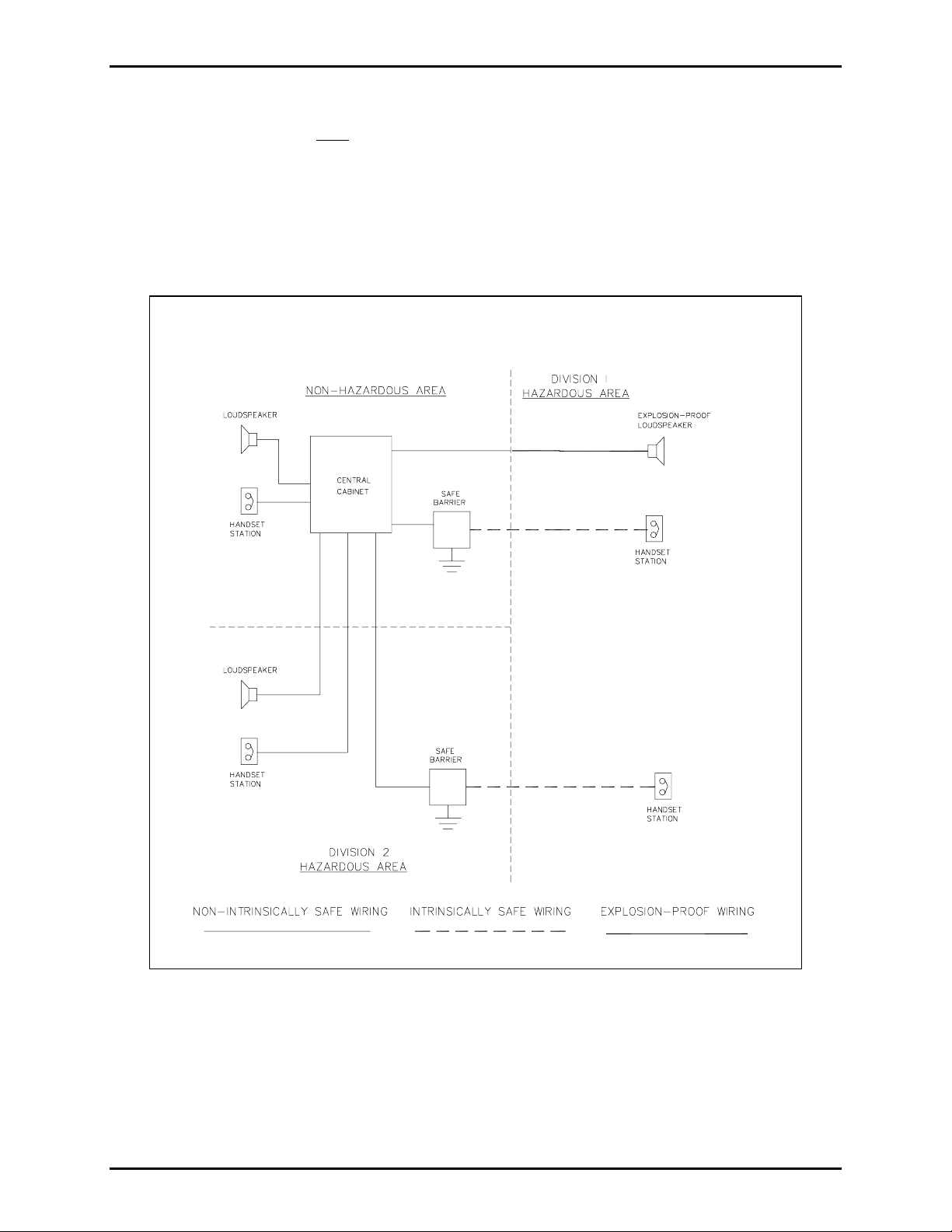
Hazard ous Areas
The Model 10461 Card Rack must
be mounte d in a no n-haz ardous a rea, although other port ions of the
Cent ra- P age syste m may be l ocated in D iv. I or Div. II haz ardous areas if app ropriate wiring
configurations and barriers are used. Refer to Pub. 42004-356, Control Drawing 72979, for proper
installa tion of sta tions f or int rins ic ally saf e operatio n in Class I, D i v. I, Group C and D hazardous areas.
A typ i c al C e ntra-Pa ge s yste m w ith c omponents in both hazardous and non-haz ardou s areas is shown in
Figure 1.
Figure 1. Typical Centra-Page System Diagram
\\s_eng\gtc proddoc s \st andard iom s - current release\42004 instr. manuals \ 42004-220b. doc
08/05
Page 3
Pub. 42004-220B
Model 10461-002 Centr a- P age Car d Rac k Page: 3 of 7
Installation
Po wer Requirements
This equipment is designed for nominal 24 V dc operation (22 to 28.8 V) with the negative side
grounded, 20 amps maximum, 2 amps idle. However, neither power supply lead is actually wired to the
ground termi nal.
The Centra-Page system may be used with negative ground, positive ground, or ungrounded power
sources. The card rack must be mounted in a non- haza rdous area.
If installing a station and line card as an add-on, please consult the following chart to ensure proper power
will be supplied.
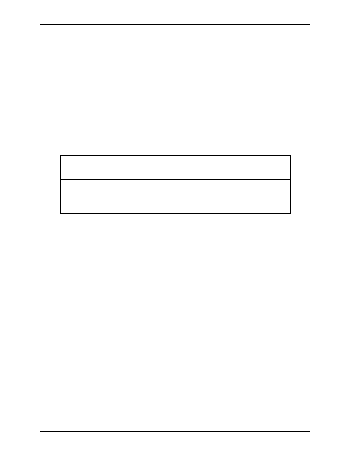
Power Supply Current Requirements
Mode 10 Cards 20 Cards 30 Cards
Standby 0.8 amp 1.5 amps 2.3 amps
Page (maximum load) 5.7 amps 11.4 amps 17.1 amps
Alarm (typical) 3.8 amps 7.5 amps 11.3 amps
Alarm (maximum level) 12.5 amps 25.0 amps 37.5 amps
Notes regarding power supply current requirements listed above:
1. Ra tings at 27.0 V dc at the central cabin et. Add 8% for page and ala rm at 2 8.8 V dc.
2. Full load is defined as 15-watt load on all cards with levels adjusted at factory; 2-watt alarm output.
3. Typical load is defined as 7.5-watt load (such as 16-ohm loudspeaker connected to 8-ohm output).
4. Maximum level is defined as 15-watt loads and level control adjusted for 15-watt alarm level on all
cards.
5. Ratings for alarm based on continuous tones. Pulse tone reduces current to about 60%.
\\s_eng\gtc proddoc s \st andard iom s - current release\42004 instr. manuals \ 42004-220b. doc
08/05
Page 4
Pub. 42004-220B
Model 10461-002 Centr a- P age Car d Rac k Page: 4 of 7
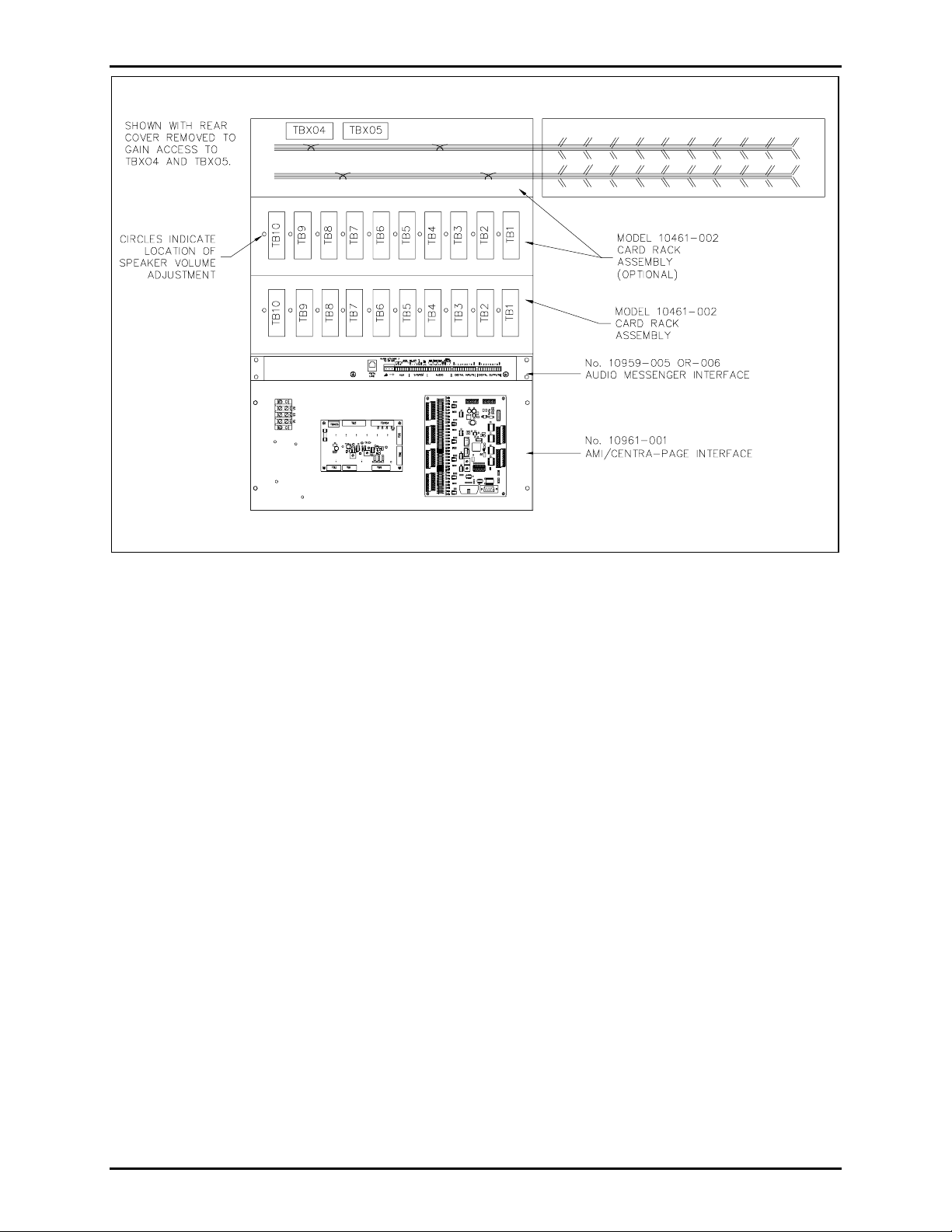
Figure 2. General Outline Details
Installa tion Procedure
1. Carefully unpack and identify the components. A parts envelope containing the mounting screws and
11 jumper wires is includ e d.
2. Refer to Figure 2. The Model 10461-002 Card Rack(s) is mounted in a Model 10468-002
Centra-Page Central Cabinet, or similar 19-inch cabinet. If mounting more than one card rack or a
Model 10961-001 AMI Centra-Page Interface, all components should be kept together. There should
be no blank panel space between these pieces of equipment or the interconnecting jumpers will not be
long e nough.
3. For easy access to TBX04 and TBX05, remove the four screws that hold the back panel on the card
rack. This is the panel with TB1 through TB10 mounted on it. Refer to Figure 2 for details.
4. Carefully swing the panel to the right as if the right side (as viewed from the rear) were hinged. Do
not put excessive strain on the wiring harnesses. TBX04 and TBX05 are now exposed.
5. Connect 22 to 28.8 V dc power to TBX05. If more than one card rack is being used, connect the
TBX05 terminal blocks with the three thick jumpers provided.
6. Connect signal and control conductors to TBX04. Be sure the wiring scheme is consistent from one
rack to the next rack.
7. When reassembling after the jumpers are in place, be certain all harnesses are returned to their
previous locations. Mount the panel to the rear, stationary portion of the Model 10468-002 Central
Cabinet.
\\s_eng\gtc proddoc s \st andard iom s - current release\42004 instr. manuals \ 42004-220b. doc
08/05
Page 5

Pub. 42004-220B
Model 10461-002 Centr a- P age Car d Rac k Page: 5 of 7
8. Wiring from the terminal blocks (TB1 through TB10) on the rear of the card rack to the associated
handset s tation and speaker c an be a c comp lished in several ways. S e e Figure 1. I n each wi ring
option, terminal connections L1, L2, P, and A on the card rack correspond to L1, L2, P, and A on the
terminal strips on each handset station. The remaining two conductors are connected to C and either
70.7 V or 8 ohm for loudspeaker wiring. See the Cabling section below for additional information.
9. Plug the Model 69037-101 Line Cards into the card rack with the card ejectors at the top, and the
components on the right.
10. Adjust the speaker level using a small standard screwdriver inserted into the hole labeled
LEVEL
.
SPKR.
If you are assembling the Centra-Page system in the field, refer to the specific instruction manuals for
individu al c ompon e nts. These manuals ex plai n in detai l how to install and connect the variou s
components of a Centra-Page system to the Model 10468-002 Central Cabinet. The manuals for these
components are listed below:
Pub. Number Component/Ti tle
42004-214 Model 473-002 Centra-Page Outdoor Wall Station
42004-215 Model 472-002 Centra-Page Permanent Indoor 2-Party Station
42004-216 Model 476-002 Centra-Page Flush Mount Station
42004-220 Model 10461-002 Centra-Page Card Rack
42004-221 Model 69037-101 Centra-Page Station Card
42004-227 Model C83018 Centra-Page Station Crew’s Quarters Mute Card
42004-371 Model 10961-001 AMI Centra-Page Interface
42004-345 Model 10959-006 Rack-Mount Audio Messenger Interface
Cabling Req uirements
GAI-Tronics recommends the use of three 18 AWG twisted pairs, with each pair of conductors
individually shielded (GAI-Tronics Model 60051 Series cable). However, as longer cable distances are
requ ired, lar ger wire s izes ma y be ap propriate. The table b e lo w lists distance limitations for 1 dB loss for
paging/speaker output.
Wire Size 8-Ohm Output 70.7 V Output
18 AWG 75 feet (25 m) 6250 feet (1900 m)
16 AWG 120 feet (35 m) 9900 feet (3000 m)
14 AWG 200 feet (60 m) 15, 800 feet (4800 m)
\\s_eng\gtc proddoc s \st andard iom s - current release\42004 instr. manuals \ 42004-220b. doc
08/05
Page 6

Pub. 42004-220B
Model 10461-002 Centr a- P age Car d Rac k Page: 6 of 7
Wiring Driv ers/Loudspeak ers to Centra-Page System
When using the common and 70.7 V output from the Centra-Page card rack, the driver unit for the
louds peaker must c onta in a 70 .7 V line-matchi ng tr ansformer . GAI-Tr onics offers the f ollow ing dr iver
products that can be used in this situation.
Hazardous Areas
Div. 2:
Model 13314-002
Model 13314-003 (70.7 volt transformer)
Div. 1:
Model 13310-201
Model 13310-203 (70.7 volt transformer)
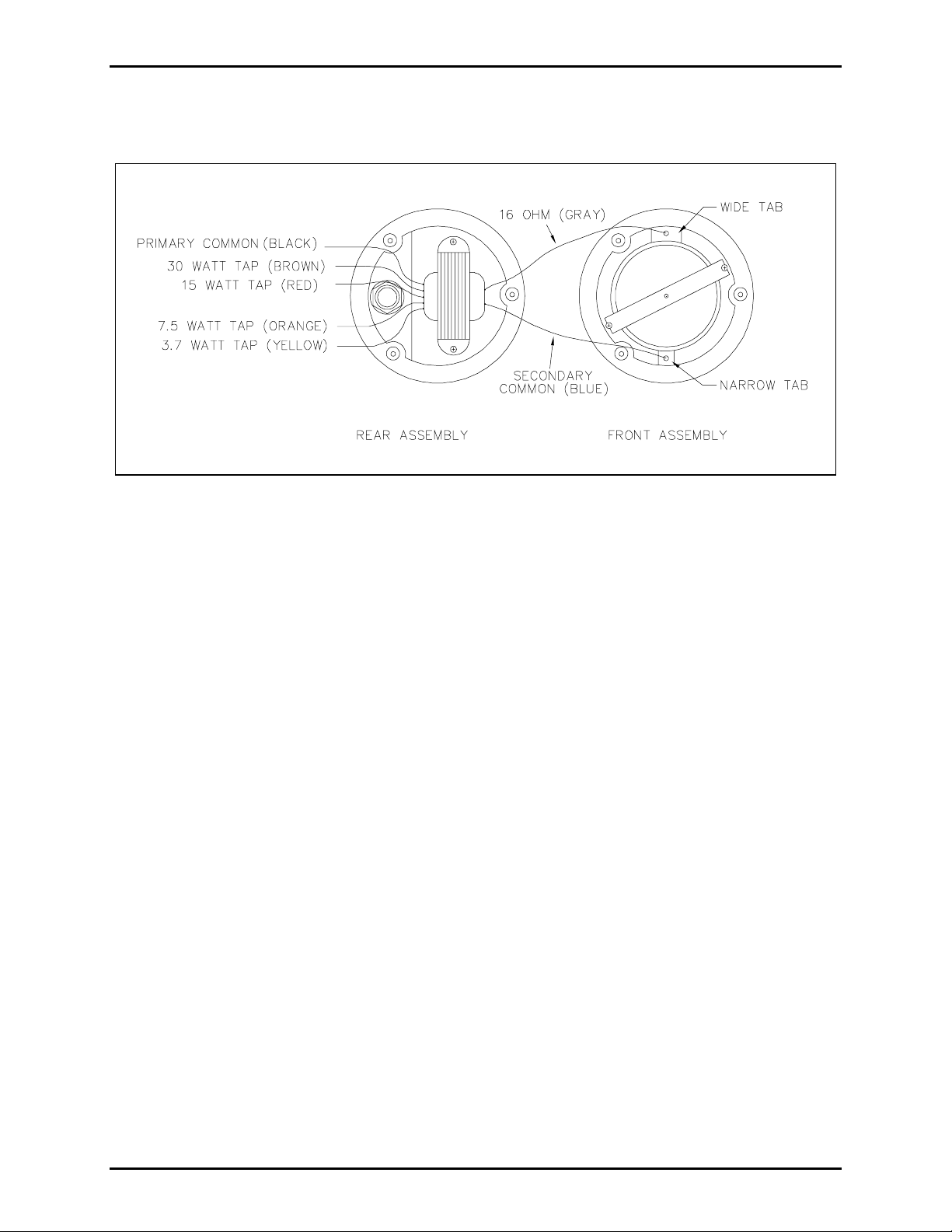
When wiring the Model 13314-003 with 70.7 V transformer driver:
• Connect the incoming common conductor to the black common conductor on the primary side of the
transformer.
• Connect the incoming 70.7 V conductor to the red, 15-watt conductor for maximum output
.
• To reduce the sound pressure level by 3 dB, connect the incoming 70.7 V conductor to the orange 7.5
watt tap.
• To reduce the SPL by another 3 dB, use the yellow 3.7-watt tap.
Please see Figure 3 for further wiring details.
When wiring the Model 13310-203 Driver:
• Connect the incoming common conductor to the white common on the primary side of the
transformer.
• Connect the incoming 70.7 V conductor to the black conductor.
• On the secondary side, connect the gray common conductor to the white conductor on the remaining
half of the driver, and the desired watt conductor to the remaining black conductor. See the table
below:
Wattage Color
30 Purple
15 Blue
10 Green
5 Orange
2.5 Brown
1.5 Yellow
\\s_eng\gtc proddoc s \st andard iom s - current release\42004 instr. manuals \ 42004-220b. doc
08/05
Page 7
Pub. 42004-220B
Model 10461-002 Centr a- P age Car d Rac k Page: 7 of 7
When using the GAI-Tronics Model 13351 Integral Speaker, connect the incoming conductors to the
labeled terminal block inside the unit according to the desired wattage tap.
Figure 3. Wiring Details for Model 13314-003
Speake r Muting
The Model 10461-002 Card Rack and Model 69037-101 Line Cards are factory-set so that all associated
spea kers broa dc ast pages made on the syste m. However , if a spea ker is located too close to a hands et ,
acou stic coupling may occ ur du rin g a page from that handset and c ause fee dback over the entire system.
To eliminate this problem, the speaker can be muted by cutting the blue wire that loops from pin 2 to pin
10 on the connector that the station card plugs into. These blue jumpers are found on each connector in
the rack.
NOTE: This muting procedure affects handset pages only, and does not affect alarm signals.
This procedure is permanent once completed. If temporary muting is required, contact your GAI-Tronics
Service Cent er for addit ional information.
Operation
The card rack it self ha s no user op erat ion fu nc tions. Refer t o the in dividual compo nent manuals for
specific op er a tio na l inst r u ct i ons .
\\s_eng\gtc proddoc s \st andard iom s - current release\42004 instr. manuals \ 42004-220b. doc
08/05
Page 8

Warranty
Equipment. GAI-Tronics warrants for a period of one (1) year from the date of shipment, that any
GAI-Tronics equipment supplied hereunder shall be free of defects in material and workmanship, shall
comply with the then-current product specifications and product literature, and if applicable, shall be fit
for the purpose specified in the agreed-upon quotation or proposal document. If (a) Seller’s goods prove
to be defective in workmanship and/or material under normal and proper usage, or unfit for the purpose
specified and agreed upon, and (b) Buyer’s claim is made within the warranty period set forth above,
Buyer may return such goods to GAI-Tronics’ nearest depot repair facility, freight prepaid, at which time
they will be repaired or replaced, at Seller’s option, without charge to Buyer. Repair or replacement shall
be Buyer’s sole and exclusive remedy. The warranty period on any repaired or replacement equipment
shall be the greater of the ninety (90) day repair warranty or one (1) year from the date the original
equipment was shipped. In no event shall GAI-Tronics warranty obligations with respect to equipment
exceed 100% of the total cost of the equipment supplied hereunder. Buyer may also be entitled to the
manufacturer’s warranty on any third-party goods supplied by GAI-Tronics hereunder. The applicability
of any such third-party warranty will be determined by GAI-Tronics.
Services. Any services GAI-Tronics provides hereunder, whether directly or through subcontractors,
shall be performed in accordance with the standard of care with which such services are normally
provided in the industry. If the services fail to meet the applicable industry standard, GAI-Tronics will
re-perform such services at no cost to buyer to correct said deficiency to Company's satisfaction provided
any and all issues are identified prior to the demobilization of the Contractor’s personnel from the work
site. Re-performance of services shall be Buyer’s sole and exclusive remedy, and in no event shall GAITronics warranty obligations with respect to services exceed 100% of the total cost of the services
provided hereunder.
Warranty Periods. Every claim by Buyer alleging a defect in the goods and/or services provided
hereunder shall be deemed waived unless such claim is made in writing within the applicable warranty
periods as set forth above. Provided, however, that if the defect complained of is latent and not
discoverable within the above warranty periods, every claim arising on account of such latent defect shall
be deemed waived unless it is made in writing within a reasonable time after such latent defect is or
should have been discovered by Buyer.
Limitations / Exclusions. The warranties herein shall not apply to, and GAI-Tronics shall not be
responsible for, any damage to the goods or failure of the services supplied hereunder, to the extent
caused by Buyer’s neglect, failure to follow operational and maintenance procedures provided with the
equipment, or the use of technicians not specifically authorized by GAI-Tronics to maintain or service the
equipment. THE WARRANTIES AND REMEDIES CONTAINED HEREIN ARE IN LIEU OF AND
EXCLUDE ALL OTHER WARRANTIES AND REMEDIES, WHETHER EXPRESS OR IMPLIED BY
OPERATION OF LAW OR OTHERWISE, INCLUDING ANY WARRANTIES OF
MERCHANTABILITY OR FITNESS FOR A PARTICULAR PURPOSE.
Return Policy
If the equipment requires service, contact your Regional Service Center for a return authorization number
(RA#). Equipment should be shipped prepaid to GAI-Tronics with a return authorization number and a
purchase order number. If the equipment is under warranty, repairs or a replacement will be made in
accordance with the warranty policy set forth above. Please include a written explanation of all defects to
assist our technicians in their troubleshooting efforts.
Call 800-492-1212 (inside the USA) or 610-777-1374 (outside the USA) for help identifying the
Regional Service Center closest to you.
(Rev. 10/06)
 Loading...