

Page 1

Pub. 42004-415B
GAI-TRONICS® CORPORATION
A HUBBELL COMPANY
Model 10458-10x
600-Ohm/RF Electronics Paging Module
T ABLE OF C ONTENTS
Confidentiality Notice .....................................................................................................................1
General Information .......................................................................................................................1
Product Overview ................................................................................................................................... 1
Features .................................................................................................................................................... 1
Available Models ..................................................................................................................................... 2
System Layout Considerations .............................................................................................................. 2
Operating Modes .............................................................................................................................2
Generic Operation .................................................................................................................................. 2
Selective Operation ........................................................................................................... ...................... 3
DTMF Selective with Manual Switch .................................................................................................................. 3
DTMF Selective with Audio Switch ..................................................................................................................... 3
Two-Tone Selective .............................................................................................................................................. 3
Volume Adjustment ................................................................................................................................ 4
Output Relay ........................................................................................................................................... 4
Programming ..................................................................................................................................4
Programming Accessories ...................................................................................................................... 5
Opening the Paging Module ................................................................................................................... 5
Audio Line Termination Jumper .......................................................................................................... 6
LED Indicators ........................................................................................................................................ 6
Fuses ......................................................................................................................................................... 7
Card Suite Software ................................................................................................................................ 7
Installation ............................................................................................................................................................ 7
Connecting the Programming Cable ..................................................................................................................... 7
Programming the Paging Module ......................................................................................................................... 8
Generic Mode ..................................................................................................................................................... 10
DTMF with Manual Switch ................................................................................................................................ 12
DTMF with Voice Switch ................................................................................................................................... 14
RF Programming Software .................................................................................................................. 16
Installation .......................................................................................................................................................... 16
Connecting the Programming Cable ................................................................................................................... 16
Programming the Radio ...................................................................................................................................... 17
Installation ....................................................................................................................................20
Safety and General Information .......................................................................................................... 20
GAI-Tronics Corporation 400 E. Wyomissing Ave. Mohnton, PA 19540 USA
610-777-1374 800-492-1212 Fax: 610-796-5954
V
ISIT WWW.GAI-TRONICS.COM FOR PRODUCT LITERATURE AND MANUALS
Page 2

TABLE OF CONTENTS P UB. 42004-415B
Outdoor Installation Product ............................................................................................................................... 20
Antenna Care ...................................................................................................................................................... 20
Electromagnetic Interference/Compatibility ....................................................................................................... 20
Mounting ................................................................................................................................................ 21
Wiring and Connections ....................................................................................................................... 23
Specifications ................................................................................................................................25
Appendix A: Speaker Zoning Example .......................................................................................27
GAI-Tronics Corporation 400 E. Wyomissing Ave. Mohnton, PA 19540 USA
610-777-1374 800-492-1212 Fax: 610-796-5954
V
ISIT WWW.GAI-TRONICS.COM FOR PRODUCT LITERATURE AND MANUALS
Page 3
Pub. 42004-415B
GAI-TRONICS® CORPORATION
A HUBBELL COMPANY
Model 10458-10x
600-Ohm/RF Electronic Paging Module
Confidential ity Notice
This manual is provided solely as an operational, installation, and maintenance guide and contains sensitive business and
technical information that is confidential and proprietary to GAI-Tronics. GAI-Tronics retains all intellectual property and other
rights in or to the information contained herein, and such information may only be used in connection with the operation of your
GAI-Tronics product or system. This manual may not be disclosed in any form, in whole or in part, directly or indirectly, to any
third party.
General Information
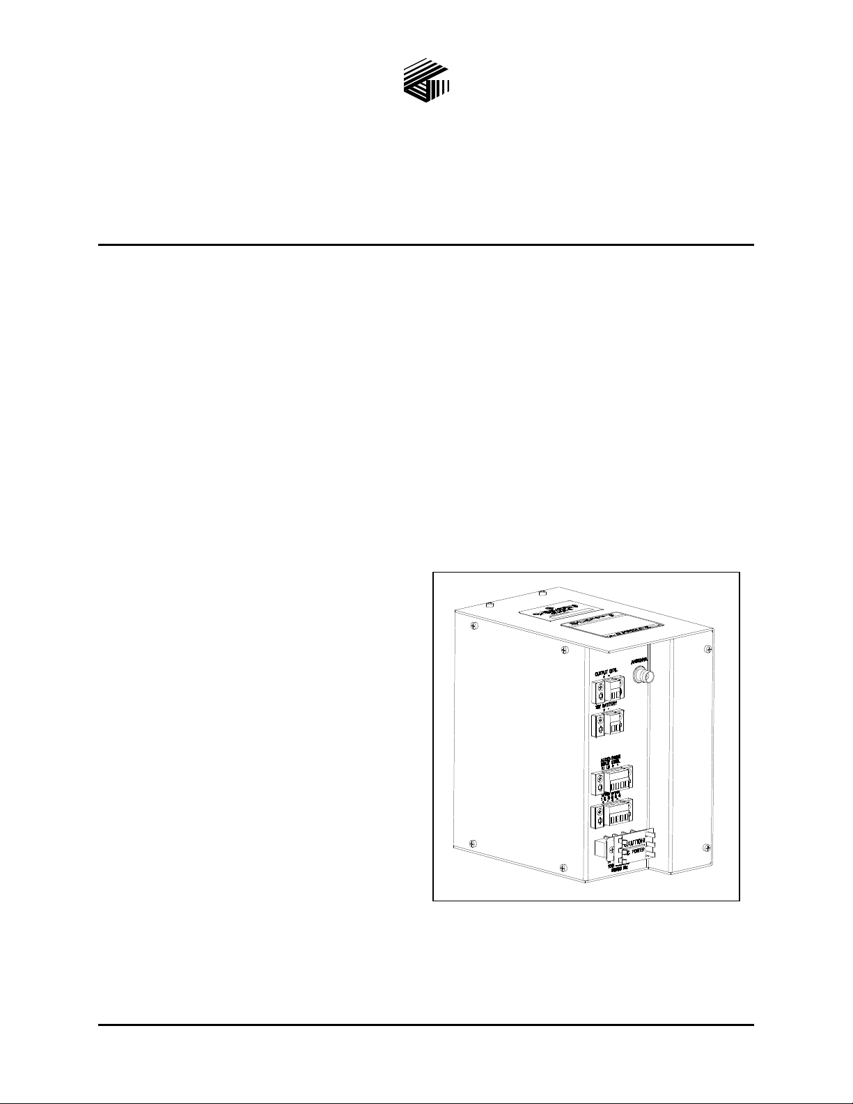
Product Overview
GAI-Tronics’ Electronics Paging Modules are mechanically designed for mounting to the access panel in
Model 234 Series Stanchions. Each paging module can be used with the Model 234SBM Stanchion
Broadcast Module or Model 234SBA Stanchion Broadcast Assembly to supply an amplified broadcast to
stanchion speakers.
Fea tures
Hardwired (600-ohm) and RF audio delivery
to amplifier.
One-way page broadcasts over system
speakers.
A high-efficiency (>80%) Class D amplifier to
provide up to 10 watts into a 4-ohm load (>110
dB SPL from each speaker, measured at 1
meter on axis).
Generic Operation - (common broadcast) using
input contact closure.
Selective Operation - addressability for
individual unit, group/zone, or system-wide
broadcasts using DTMF or 2-Tone signaling
access.
Remote volume control using DTMF
signaling.
Universal ac input power supply provided.
Battery trickle charge during normal operation.
Programmable output control for strobe activation.
PC programmable using the CARD Suite Programming Software Application.
Figure 1.
GAI-Tronics Corporation 400 E. Wyomissing Ave. Mohnton, PA 19540 USA
610-777-1374 800-492-1212 Fax: 610-796-5954
V
ISIT WWW.GAI-TRONICS.COM FOR PRODUCT LITERATURE AND MANUALS
Page 4

Pub. 42004-415B
Model 10458-10x 600-Ohm/RF Electronics Paging Module Page 2 of 28
Available Mode ls
Part No. Description
10458-101 Hardwired 600-ohm audio input
10458-102 Hardwired 600-ohm input and/or VHF radio receiver input (154–174 MHz)
10458-103 Hardwired 600-ohm input and/or UHF radio receiver input (450–470 MHz)
System Layout C onsiderations
The installer must consider the system layout to assure proper audio delivery to the Electronics Paging
Module.
For hardwired installations, each paging module requires a balanced 600-ohm, 0 dBm input audio
signal. A contact closure may be required depending on the selected operating mode. Cabling
(telephone cable, cat-5/6, etc.) must be distributed appropriately to attain the necessary audio level
and balance. Audio distribution apparatus may be necessary to accomplish this task.
For RF installations, each paging module must be located within range of the RF transmitting device.
Operating Modes
The Electronics Paging Modules can operate in two different modes, referred to as Generic and Selective.
The mode of operation determines if the paging module’s speakers will broadcast all audio transmissions
or only “selective” audio transmissions. Each operating mode is described below.
Generic Operation
Generic Mode requires an external control input to activate (wake up) the paging module. Once active,
the unit will broadcast any audio received from the transmitting device. Removal of the activation input
returns the paging module to the inactive (sleep) mode.
For hardwired installations, the control input activation must be in the form of a voltage–free (dry)
contact closure.
For RF installations, the control input activation is provided from the “RF carrier detect” control
circuit of the integral radio receiver.
All paging modules are factory programmed for Generic Operation.
e:\standard ioms - current release\42004 instr. manual s\42004-415b.doc
03/15
Page 5

Pub. 42004-415B
Model 10458-10x 600-Ohm/RF Electronics Paging Module Page 3 of 28
Selective Operation
Selective operation allows “addressable” access to each paging module using DTMF signaling (DTMF
Selective) or Two-Tone signaling (Two-Tone Selective). Each paging module can be programmed with
up to eight different addresses. Upon receiving a valid DTMF or Two-Tone code, the paging module
becomes active and will broadcast any audio received from the transmitting device. The paging module
returns to the inactive (sleep) mode when the transmission is complete and a pre-programmed hold time
expires.
By assigning a combination of addresses to each device, the overall system can be segregated into
multiple broadcast zones. In a typical multi-zone system, three access codes are assigned to each module.
Address 1 – is always a unique address assigned to only that paging module. By using this access
code, an individual paging module is activated.
Address 2 – could be an address assigned to a group of paging modules located in the same speaker
broadcast zone. When received, the group of paging modules is activated simultaneously. This
access method is used when an audio broadcast is required to a particular broadcast zone.
Address 3 – could be an address assigned to all paging modules in the system. By using this access
code, all paging modules are activated simultaneously when a system-wide audio broadcast is
required.
DTMF Selective with Manual Switch
Requires an external control input to activate (wake up) the paging module. Once active, the unit must
receive a valid DTMF address. Upon receiving a valid address, the paging module will broadcast any
audio received from the transmitting device. Removal of the activation input returns the paging module
to the inactive (sleep) mode.
For hardwired installations, the control input activation must be in the form of a voltage–free (dry)
contact closure.
For RF installations, the control input activation is provided from the “RF carrier detect” control
circuit of the integral radio receiver.
GAI-Tronics CARD Suite Programming Software is used to assign the operating mode and DTMF
addresses. Valid DTMF addresses can contain up to eight digits (0–9) followed by the “#” symbol. The
“#” symbol is automatically inserted by the programming software. Each paging module can be
programmed with up to eight different addresses.
DTMF Selective with Audio Switch
This mode is used for hardwired installation where a contact closure is not available from the transmitting
device. In this case, the paging module ignores the input contact and constantly monitors the audio line
for a valid DTMF address. Upon receiving a valid address, the paging module will broadcast any
subsequent audio received from the transmitting device. The paging module returns to the inactive
(sleep) mode after audio from the transmitting device stops for a pre-programmed time.
Two-Tone Selective
GAI-Tronics CARD Suite Programming Software is used to assign Two-Tone access codes. Valid access
codes contain two frequencies in the 400–2700 Hz range. Each paging module can be programmed with
up to eight different codes. By assigning a combination of access codes to each device, the overall system
can be segregated into different speaker broadcast zones as described above for DTMF signaling. TwoTone signaling is only applicable for RF installations. Contact the Service Center for instructions in using
CARD Suite to set up Two-Tone Selective.
e:\standard ioms - current release\42004 instr. manual s\42004-415b.doc
03/15
Page 6

Pub. 42004-415B
Model 10458-10x 600-Ohm/RF Electronics Paging Module Page 4 of 28
Volume Adjustment
The paging module’s speaker volume can be adjusted remotely using DTMF signaling. To change the
speaker volume, the paging module must first be accessed using either Generic or Selective operating
modes as described above.
Once active, the operator must enter the “*” symbol from the DTMF keypad on the transmitting device
(telephone, radio, etc.). Upon receiving the “*”, the paging module activates a test tone that is broadcast
from speakers at the current volume setting.
To increase the volume, the operator enters another “*” symbol while the test tone is broadcasting.
Each time the “*” symbol is pressed, the test tone volume will increase slightly.
To decrease the volume, the operator enters the “#” symbol while the test tone is broadcasting. Each
time the “#” symbol is pressed, the test tone volume will decrease slightly.
When the desired volume has been reached, disconnect from the system and allow the paging module to
time out and return to inactive (sleep) mode. The speaker volume level will remain at the new setting for
all subsequent broadcasts until changed again.
Output Relay
The Electronics Paging Module is capable of providing a low current relay output designed for activating
a GAI-Tronics Model 530-001 Strobe Light. This output is programmable for activation via all or
selected DTMF addresses and can be programmed for maintained or time-out operation. Contacts can be
normally-open or normally-closed. The output’s maximum current capability is 100 mA if used for
activation of an external device other than the Model 530-001 Strobe Light. Items requiring higher
current will require an interposing relay between the paging module output and the actual device.
Programming
The Electronics Paging Module requires software configuration to set the operating parameters. It is
highly recommended to program and bench-test the unit prior to field installation into the GAI-Tronics
234 Series Stanchion.
A computer with a COM port (RS-232) and Windows95 or newer operating system is required to
program the paging module. Windows NT operating system is not supported. If the PC contains only
USB ports, a USB to RS-232 converter is also required. Programming accessories are sold separately.
They are as described below:
The CARD Suite Programming Software (Version 4.3.2 or newer) and programming cable are used to
program the operating parameters of the Model 10458-101, 10458-102 and 10458-103 Electronics Paging
Modules.
The Model 10458-102 and -103 RF Electronics Paging Modules also require the radio receiver to be
programmed. The RF programming kit includes the software and cable for programming the desired
frequency and optional PL code into the radio receiver.
e:\standard ioms - current release\42004 instr. manual s\42004-415b.doc
03/15
Page 7
Pub. 42004-415B
Model 10458-10x 600-Ohm/RF Electronics Paging Module Page 5 of 28
Programming Accessories
Part No. Description
XAC4000B CARD Suite Programming Software Flash - Version 4.3.2 or newer (needed for all
models)
XAC0004A Programming Cable (needed for all models)
19101-024 RF Module Programming Kit (needed for Models 10458-102 and -103 only) consists of:
Ritron DTX L-Series Programming CD
9/RTC-PAS Cable
DTXP-PAC Cable Adaptor
2147C001 9-pin to 25-pin Sub D Adaptor
Opening the P aging Module
The paging module must be opened for programming, setting an internal jumper, and mounting the
paging module to the Model 234 Stanchion. Each is described in more detail later in this manual. The
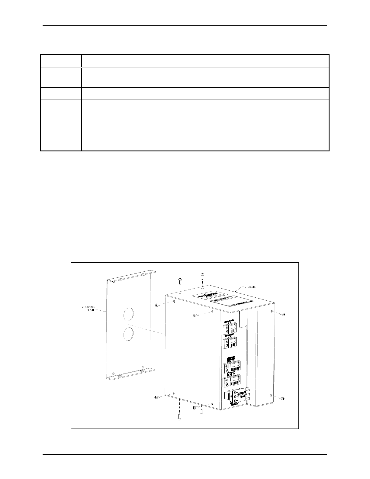
following steps describe how to open the paging module:
1. Remove the four screws (two on top and two on bottom) holding the mounting plate to the chassis.
The mounting plate has two finger holes that can be used to remove the mounting plate from the
chassis.
2. Remove the six screws that are holding the chassis together (two on the rear and four on the side).
Refer to Figure 2 below.
Figure 2. Electronic Paging Module Assembly.
e:\standard ioms - current release\42004 instr. manual s\42004-415b.doc
03/15
Page 8
Pub. 42004-415B
Model 10458-10x 600-Ohm/RF Electronics Paging Module Page 6 of 28
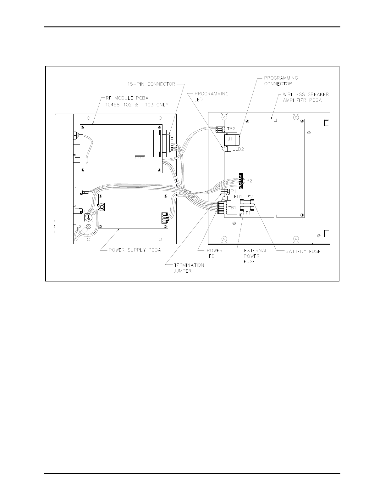
3. Carefully open the chassis, keeping the U-bracket to the right. The Speaker Amplifier PCBA is
mounted on the U-bracket and is where the settings and adjustments exist. Refer to Figure 3.
Figure 3. Electronics Paging Module (opened)
Audio Line T ermination J umper
For hardwired installations the paging module contains a jumper to terminate the audio line cable.
Jumper P1 on the speaker amplifier PCBA configures the unit for 600-ohm or 15k-ohm line termination.
Shorting pins 1 and 2 set the line termination to 15k ohms (default setting). Shorting pins 2 and 3 set the
line termination to 600 ohms. The settings options are labeled next to the jumper on the PCBA. See
Figure 3 for location of P1.
For RF installations, this jumper has no function.
LED Indica tors
Two LED indicators are located on the speaker amplifier PCBA, but are visible only when the module is
opened. The Power LED is activated when the unit is powered. The Programming LED indicates when
the unit is properly connected to a programming computer using CARD Suite Programming Software.
Refer to Figure 3 for LED locations.
e:\standard ioms - current release\42004 instr. manual s\42004-415b.doc
03/15
Page 9

Pub. 42004-415B
Model 10458-10x 600-Ohm/RF Electronics Paging Module Page 7 of 28
Fuses
There are two fuses (F1 and F2) located on the speaker amplifier PCBA
Fuse F1 is a 3-amp fuse that limits the current draw from the 12 V dc power supply. Replace F1 with
Littelfuse (3 amp) 5 × 20 mm or Cooper Bussman (3 amp) 5 × 20 mm fuses only.
Fuse F2 is a 5-amp fuse that limits the current draw from the 12 V dc battery. Replace F2 with Littelfuse
(5 amp) 5 × 20 mm or CooperBussman (5 amp) 5 × 20 mm fuses only.
Card Suite Softw are
Installation
Exit all other programs that are running until the installation is complete.
Place the flash drive in the computer USB port.
If the installation does not start up automatically, it can be run from the Start menu. Select the Start
button; then select Run. At the prompt, type x:\Software Select Menu.exe where x represents the
drive letter that is associated with your flash drive. A CARD Suite icon should appear on the desktop
display after successful installation.
Connecting the Programming Cable
1. Attach the programming cable to the COM1 or COM2 serial port connector on the computer using
the 9-pin adaptor supplied with the cable.
OTE: If using a USB-to-RS-232 converter, connect the converter to the computer’s USB port and
N
then connect the programming cable to the 9-pin mating receptacle on the converter.
2. After opening the paging module (as previously described), plug the programming cable into the
programming connector J1 on the speaker amplifier PCBA. Refer to Figure 3.
3. Connect a 12 V dc power source to the terminal block labeled BATTERY, located on the front
section of the paging module assembly. Be sure to observe the voltage polarity.
4. Verify the Power LED and the Programming LED illuminate on the speaker amplifier PCBA. The
Power LED indicates the 12 V dc is properly connected and the Programming LED verifies the
computer and programming cable are connected properly.
e:\standard ioms - current release\42004 instr. manual s\42004-415b.doc
03/15
Page 10
Pub. 42004-415B
Model 10458-10x 600-Ohm/RF Electronics Paging Module Page 8 of 28
Programming the Paging Module
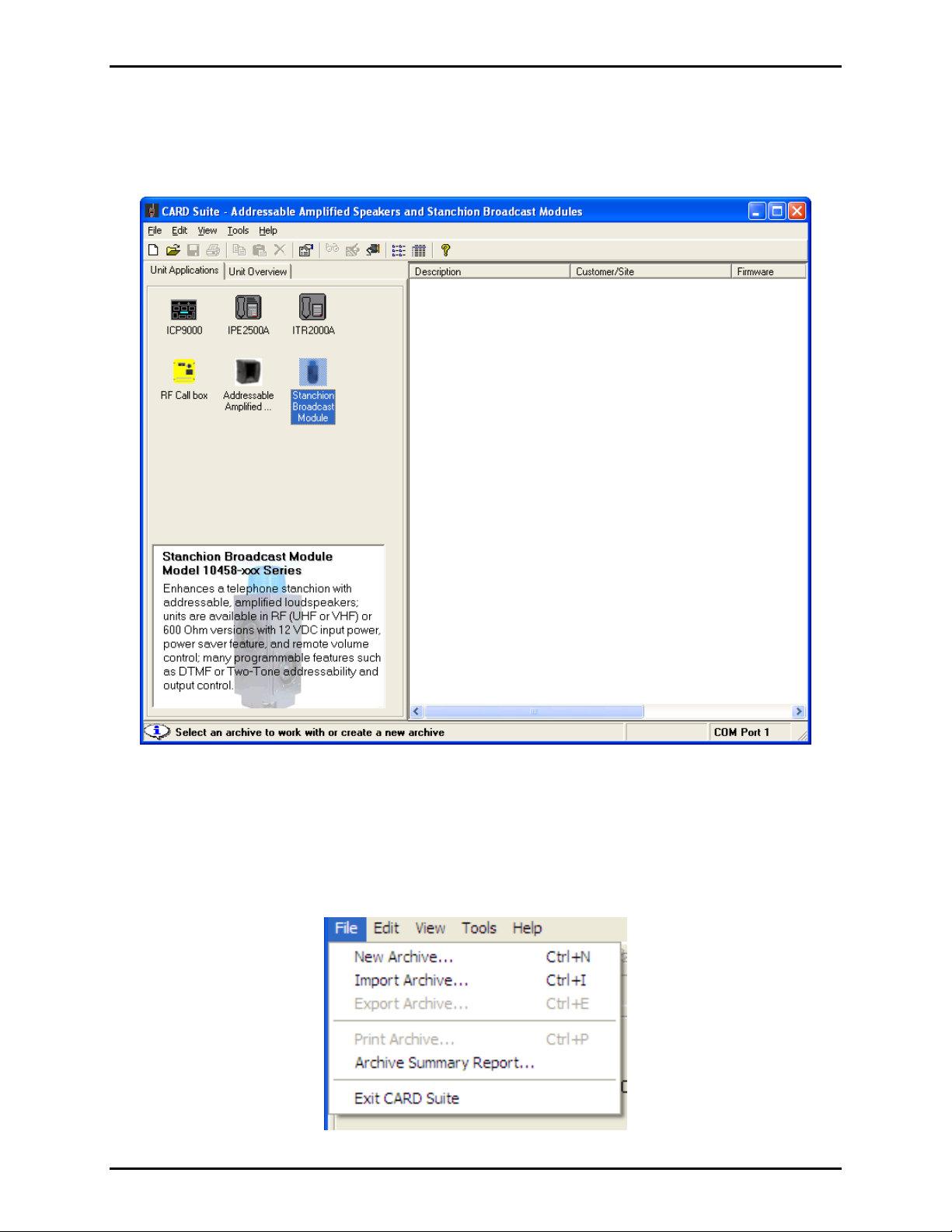
Run the CARD Suite Programming Software on the PC. The following screen will appear:
Select the Stanchion Broadcast Module icon on the left pane of the screen.
Any existing stanchion module archives or speaker archives that are stored in CARD Suite on this PC are
shown in the pane on the right side of the screen. These archives can be modified by double-clicking the
archive entry in the right pane.
To add a new speaker archive, select File New Archive from the tool bar as shown below. One
archive is required for each paging module in the system.
e:\standard ioms - current release\42004 instr. manual s\42004-415b.doc
03/15
Page 11

Pub. 42004-415B
Model 10458-10x 600-Ohm/RF Electronics Paging Module Page 9 of 28
The following screen will be displayed when adding a new archive:
1. Enter an Archive Description
for the paging module archive as shown above. The description is
generally the device’s location within the end-user’s facility or a tag number identification assigned
by the system installer.
2. Enter the Customer/Site description. This is generally the facility name. This entry is useful when
managing speakers at multiple facilities. It will allow the system administrator to easily sort the
speaker entries when making changes or updates to the speaker programming.
3. Select the archive creation Method using the radio buttons. To upload an existing configuration
from the connected paging module, select Create new unit
archive by reading connected
unit.
If a paging module is not connected or the programmer wants to create a new archive starting with
default values, select: Create new unit archive using defalt values.
4. Select OK. The archive will be created and then opened for editing. (The “reading connected unit”
creation requires about 15 seconds.)
5. Enter a name or initials in Last Modified By field (optional). This is a method to track
programming changes by date and user.
e:\standard ioms - current release\42004 instr. manual s\42004-415b.doc
03/15
Page 12

Pub. 42004-415B
Model 10458-10x 600-Ohm/RF Electronics Paging Module Page 10 of 28
6. Select the Configuration tab to display the Configuration screen where all the paging module’s
operation parameters are set.
7. Select the Operation Mode from the pull-down menu. The screen will change appearance based on
the selection made. Each selection is shown below.
Generic Mode
Volume Level - Select the speaker output level using the slide bar. The valid range is 4 mW to 8 W in
doubling increments (4 mW, 8 mW, 16 mW, etc.).
Automatic Level Adjust – This feature is not compatible with the 10458-10x series Paging Modules.
Always use the setting Disabled.
Volume Adjust Address – enter the DTMF Address code to be used for making volume changes from
a remote touch-tone device. The address should be a code unique to this unit. This address code may
include digits 0–9 as well as the extended DTMF digits A, B, C, and D. It can contain up to eight digits.
By using one or more of the DTMF digits A, B, C, or D, broadcast access will be restricted to equipment
capable of generating these DTMF digits.
e:\standard ioms - current release\42004 instr. manual s\42004-415b.doc
03/15
Page 13

Pub. 42004-415B
Model 10458-10x 600-Ohm/RF Electronics Paging Module Page 11 of 28
Test Tone Volume Adjust – The unit will generate a tone at the current volume setting when it enters
the test tone mode. This entry sets the duration of the test tone. When the unit volume is adjusted (in test
tone mode), the unit will generate a tone at the newly selected level. The valid range is 0.5–6.0 seconds
in 0.5-second increments.
Output Contact
These settings control the activation of the paging module’s contact closure output. The settings are in
effect only when the paging module is activated. Use the pull-down menu to make one of the following
selections:
No Change – Disables the output contact.
Activate – The output contact will change state when the input control contact is received and the
module becomes active. The output contact returns to the normal state when the input contact opens.
Activate + Hold – The output contact will change state when the input control contact is received.
The output contact returns to the normal state after the input contact opens and the Hold Time
duration expires.
Use the slide bar to set the Hold Time. Valid range is 1 second to 30 minutes.
Using the radio button, select the normal state of the relay contact with power applied to the paging
module. When power is removed, the contact will always be in the OPEN state.
Normally Open – relay contact is OPEN when the unit is inactive and CLOSED when active.
Normally Closed - relay contact is CLOSED when the unit is inactive and OPEN when active.
Low Battery Alert
Battery Checking – Select this checkbox to set the unit to test the battery voltage every 4 minutes.
If the battery voltage is low when the battery test occurs, the unit will broadcast a short alert tone.
The factory default “low battery” threshold is 11.5 V. If a backup battery is not connected to the
Paging Module, do not enable the Battery Checking.
Alert Tone Volume – Selects the volume of the “low” alert tone as a fraction of the unit’s speaker
output level. The factory default setting is 50%.
e:\standard ioms - current release\42004 instr. manual s\42004-415b.doc
03/15
Page 14

Pub. 42004-415B
Model 10458-10x 600-Ohm/RF Electronics Paging Module Page 12 of 28
DTMF with Manual Switch
Volume Level - Select the speaker output level using the slide bar. The valid range is 4 mW to 8 W in
doubling increments (4 mW, 8 mW, 16 mW, etc.).
Automatic Level Adjust – This feature is not compatible with the 10458-10x series Paging Modules.
Always use the setting Disabled.
Test Tone Volume Adjust – The unit will generate a tone at the current volume setting when it enters
the test tone mode. This entry sets the duration of the test tone. When the unit volume is adjusted (in test
tone mode), the unit will generate a tone at the newly selected level. The valid range is 0.5–6.0 seconds
in 0.5-second increments.
DTMF Address & Description 1–8
Enter the DTMF addresses to activate the paging module. A description of up to 12 characters can be
entered for each address. Each address can contain up to eight digits. Up to eight different addressed can
be programmed.
Address 1 is always a unique address assigned only to this paging module. It is used for individual
paging module access, and speaker volume control using additional DTMF commands. Refer to Volume
Adjustment section.
e:\standard ioms - current release\42004 instr. manual s\42004-415b.doc
03/15
Page 15

Pub. 42004-415B
Model 10458-10x 600-Ohm/RF Electronics Paging Module Page 13 of 28
Addresses 2 through 8 are typically assigned to groups of paging modules to create speaker broadcast
zones thought out the system. Paging modules assigned to the same group or zone address will activate
simultaneously when the address is received.
A typical programming scenario is to use one address for individual access, two to six addresses for zone
access, and one address for system-wide (all-call) access. The all-call address would be programmed into
every paging module.
Each address code may include digits 0–9, *, as well as the extended DTMF digits A, B, C, D. It can
contain up to eight digits. By using one or more of the DTMF digits A, B, C, or D, broadcast access will
be restricted to equipment capable of generating these extended DTMF digits.
Output Contact Function
These settings control the activation of the paging module’s contact closure output for each DTMF
address. The settings are in effect only then the paging module is activated. Use the pull-down menu to
make one of the following selections:
No Change – The output contact will be unaffected when the corresponding DTMF address is
received.
Activate – The output contact will change state when the corresponding DTMF address is received.
The output contact returns to the normal state when the Standby Time duration (3 seconds) expires.
Activate+Hold – The output contact will change state when the corresponding DTMF address is
received. The output contact returns to the normal state when the Standby Time and the Hold Time
durations expire.
De-Activate – If active, the relay will reset to its normal state immediately after receiving the
corresponding DTMF address. This is a function used to override the Standby Time and Hold Time
assigned to other DTMF addresses.
Use the slide bar to set the Hold Time. Valid range is 1 second to 30 minutes.
Using the radio button, select the normal state of the relay contact. This will be the relay state when
power is applied to the paging module. When power is removed, the contact will always be in the OPEN
state.
Normally Open – Relay contact is OPEN when the unit is inactive and CLOSED when active.
Normally Closed - Relay contact is CLOSED when the unit is inactive and OPEN when active.
Low Battery Alert
Battery Checking – Select this checkbox to set the unit to test the battery voltage every 4 minutes.
If the battery voltage is low when the battery test occurs, the unit will broadcast a short alert tone.
The factory default “low battery” threshold is 11.5 V. If a backup battery is not connected to the
Paging Module, do not enable the Battery Checking.
Alert Tone Volume – Selects the volume of the “low” alert tone as a fraction of the unit’s speaker
output level. The factory default setting is 50%.
e:\standard ioms - current release\42004 instr. manual s\42004-415b.doc
03/15
Page 16

Pub. 42004-415B
Model 10458-10x 600-Ohm/RF Electronics Paging Module Page 14 of 28
DTMF with Voice Switch
Volume Level - Select the speaker output level using the slide bar. The valid range is 4 mW to 8 W in
doubling increments (4 mW, 8 mW, 16 mW, etc.).
Automatic Level Adjust – This feature is not compatible with the 10458-10x series Paging Modules.
Always use the setting Disabled.
Test Tone Volume Adjust – The unit will generate a tone at the current volume setting when it enters
the test tone mode. This entry sets the duration of the test tone. When the unit volume is adjusted (in test
tone mode), the unit will generate a tone at the newly selected level. The valid range is 0.5–6.0 seconds
in 0.5-second increments.
Voice Switch
- Select the silence limit using the slide bar. The unit will return to inactive (sleep) mode
if audio is not received in this amount of time. The valid range is 3–10 seconds in 0.5 second increments.
DTMF Address & Description 1–8
Enter the DTMF addresses to activate the paging module. A description of up to 12 characters can be
entered for each address. Each address can contain up to eight digits. Up to eight different addressed can
be programmed.
e:\standard ioms - current release\42004 instr. manual s\42004-415b.doc
03/15
Page 17

Pub. 42004-415B
Model 10458-10x 600-Ohm/RF Electronics Paging Module Page 15 of 28
Address 1 is always a unique address assigned only to this paging module. It is used for individual
paging module access, and speaker volume control using additional DTMF commands. Refer to Volume
Adjustment section.
Addresses 2 through 8 are typically assigned to groups of paging modules to create speaker broadcast
zones thought out the system. Paging modules assigned to the same group or zone address will activate
simultaneously when the address is received.
A typical programming scenario is to use one address for individual access, two to six addresses for zone
access, and one address for system-wide (all-call) access. The all-call address would be programmed into
every paging module.
Each address code may include digits 0–9, *, as well as the extended DTMF digits A, B, C, D. It can
contain up to eight digits. By using one or more of the DTMF digits A, B, C, or D, broadcast access will
be restricted to equipment capable of generating these extended DTMF digits.
Output Contact Function
These settings control the activation of the paging module’s contact closure output for each DTMF
address. The settings are in effect only then the paging module is activated. Use the pull-down menu to
make one of the following selections:
No Change – The output contact will be unaffected when the corresponding DTMF address is
received.
Activate – The output contact will change state when the corresponding DTMF address is received.
The output contact returns to the normal state when the Standby Time duration (3 seconds) expires.
Activate+Hold – The output contact will change state when the corresponding DTMF address is
received. The output contact returns to the normal state when the Standby Time and the Hold Time
durations expire.
De-Activate – If active, the relay will reset to its normal state immediately after receiving the
corresponding DTMF address. This is a function used to override the Standby Time and Hold Time
assigned to other DTMF addresses.
Use the slide bar to set the Hold Time. Valid range is 1 second to 30 minutes.
Using the radio button, select the normal state of the relay contact. This will be the relay state when
power is applied to the paging module. When power is removed, the contact will always be in the OPEN
state.
Normally Open –relay contact is OPEN when the unit is inactive and CLOSED when active.
Normally Closed - relay contact is CLOSED when the unit is inactive and OPEN when active.
Low Battery Alert
Battery Checking – Select this checkbox to set the unit to test the battery voltage every 4 minutes.
If the battery voltage is low when the battery test occurs, the unit will broadcast a short alert tone.
The factory default “low battery” threshold is 11.5 V. If a backup battery is not connected to the
Paging Module, do not enable the Battery Checking.
Alert Tone Volume – Selects the volume of the “low” alert tone as a fraction of the unit’s speaker
output level. The factory default setting is 50%.
e:\standard ioms - current release\42004 instr. manual s\42004-415b.doc
03/15
Page 18

Pub. 42004-415B
Model 10458-10x 600-Ohm/RF Electronics Paging Module Page 16 of 28
RF Programming Software
Installation
Exit all other programs that are running until the installation is complete.
Place the CD in the computer CD-ROM drive. If the “auto-run” feature on your CD-ROM drive is
enabled, the CARD Suite menu screen should appear within a few seconds.
If the installation does not start up automatically, it can be run from the Start menu. Select the Start
button; then select Run. At the prompt, type x:\fscommand\setup.exe where x represents the drive
letter that is associated with your CD-ROM drive. A CARD Suite icon should appear on the desktop
display after successful installation.
Connecting the Programming Cable
1. Unplug the paging module’s 15-pin D-connector from the radio.
2. Connect the DTXP-PAC cable assembly’s 15-pin D-connector into the radio.
3. Connect the RJ11-style plug of the 9/RTC-PAS cable into the mating receptacle on DTXP-PAC
cable.
4. Connect the DB-9 to DB-25 adaptor to the other end of the 9/RTC-PAS cable.
5. Connect the DB-9 connector of the of the cable assembly to the computer serial port.
OTE: If using a USB-to-RS-232 converter, connect the converter to the computer’s USB port and
N
then connect the cable to the 9-pin mating receptacle on the converter.
6. Connect the red and black leads of the 9/RTC-PAS cable to a 12 V dc source (battery or power
supply), observing the polarity (red +, black-).
e:\standard ioms - current release\42004 instr. manual s\42004-415b.doc
03/15
Page 19

Pub. 42004-415B
Model 10458-10x 600-Ohm/RF Electronics Paging Module Page 17 of 28
Programming the Radio
1. Make sure the radio to be programmed is powered and connected to the PC (as described above)
before starting the programming software on the PC.
OTE: If the Ritron software does not read the type of the connected radio, unplug the programming
N
cable and re-insert.
2. The radio’s current programming will be displayed. Below is an example:
OTE: The Electronic Paging Module uses only the frequency programmed for channel 8. Be sure
N
to program channel 8 with the licensed frequency. The RF Module is capable of being
programmed for channels 1–8.
e:\standard ioms - current release\42004 instr. manual s\42004-415b.doc
03/15
Page 20

Pub. 42004-415B
Model 10458-10x 600-Ohm/RF Electronics Paging Module Page 18 of 28
3. Enter the Receive (Rx) frequency into channel 8. This is the only frequency that must be
programmed. To enter the frequency, select channel 8 then the Edit button on the left to display the
following screen:
4. Enter the Rx Frequency, and select a Quiet Call (QC) frequency or Digital Quiet Call (DQC)
code, if desired.
e:\standard ioms - current release\42004 instr. manual s\42004-415b.doc
03/15
Page 21

Pub. 42004-415B
Model 10458-10x 600-Ohm/RF Electronics Paging Module Page 19 of 28
5. After entering the frequency and optional QC or DQC, program the radio by selecting File >
Program Radio from the tool bar.
6. After the radio is programmed (time bar will disappear), disconnect the programming cable and
reconnect the DB-15 cable to the speaker amplifier PCBA.
e:\standard ioms - current release\42004 instr. manual s\42004-415b.doc
03/15
Page 22

Pub. 42004-415B
Model 10458-10x 600-Ohm/RF Electronics Paging Module Page 20 of 28
Installation
Safety and General Info rmation
Installation should only be performed by qualified service personnel in accordance with the National
Electrical Code or applicable local codes.
Read, follow, and retain instructions – All safety and operating instructions should be read and followed
before operating the unit. Retain instructions for future reference.
Heed warnings – Adhere to all warnings on the unit and in the operating instructions.
Attachments – Attachments not recommended by the product manufacturer should not be used, as they
may cause hazards.
Servicing – Do not attempt to service this unit by yourself. Opening or removing covers may expose you
to dangerous voltage or other hazards. Refer all servicing to qualified service personnel.
This permanently connected apparatus must have an ALL-POLE MAINS switch with a contact separation
of at least 3mm in each pole incorporated in the electrical installation of the building.
Outdoor Installation Product
Power lines - An outdoor system should not be located in the vicinity of overhead power lines, electric
lights, or power circuits, where it may contact such power lines or circuits, as this contact might be fatal.
Refer to the National Electrical Code Article 800 regarding installation.
Antenna Care
Unauthorized antennas, modifications, or attachments could damage the radio and may violate FCC
regulations.
Electromagnetic Interference/Compatibility
Electronic equipment may be susceptible to electromagnetic interference. If you experience interference,
visit the FCC website at http://www.fcc.gov for possible solutions.
e:\standard ioms - current release\42004 instr. manual s\42004-415b.doc
03/15
Page 23

Pub. 42004-415B
Model 10458-10x 600-Ohm/RF Electronics Paging Module Page 21 of 28
Mounting
1. Remove access panel from the Model 234 Stanchion (if applicable).
2. Remove the back plate from the paging module by removing the four #6-32 screws. Refer to Figure
4.
Figure 4. Exploded View of Paging Module
e:\standard ioms - current release\42004 instr. manual s\42004-415b.doc
03/15
Page 24

Pub. 42004-415B
Model 10458-10x 600-Ohm/RF Electronics Paging Module Page 22 of 28
3. The Model 12510-002 or Model 12510-003 Access Panel Kit (sold separately) contains four #6-32
studs to attach the paging module. Attach the plate to the #6-32 studs with the provided #6 keps nuts.
Be sure to note the orientation of the access panel when attaching the plate. Refer to Figure 5.
Figure 5. Electronics Paging Module Attachment to Front Panel
4. Attach the remainder of the paging module to the back plate/access panel assembly with the four #6-
32 screws. Note orientation of the module.
5. Attach the access panel/paging module to the Model 234 Stanchion.
e:\standard ioms - current release\42004 instr. manual s\42004-415b.doc
03/15
Page 25

Pub. 42004-415B
Model 10458-10x 600-Ohm/RF Electronics Paging Module Page 23 of 28
Wiring and Connections
The paging module provides terminal blocks on the front of the assembly for all field wiring. Each
terminal block is labeled to indicate the functionality. Refer to Figure 6 for a sample wiring diagram.
1. After installing all speaker kits and antenna kit (for RF installations), make sure all wires & cables
from the components are at the bottom of the 234 Series Stanchion.
2. Connect the black/white and white/black speaker wires to the 4-point speaker connector. Speakers 1
and 2 are parallel wired onto terminals labeled 1
terminals labeled 3
& 4.
3. For hardwired audio installations:
& 2. Speakers 3 and 4 are parallel wired onto
Connect the audio input wires to the terminals labeled A
UDIO INPUT L1&L2. Polarity for the
audio wires is not important. The audio cable must be a twisted pair to prevent noise pickup on
the line.
Connect the contact closure input wires (if used) across the terminals labeled
AGE CTRL + and –.
P
4. For RF installations, plug in the BNC connector on the antenna cable into the paging module.
5. Connect the battery wires to the battery connector observing the + (red) and (-) black polarity.
6. Connect the violet and orange wires from the GAI-Tronics Model 530-001 Strobe Light to the
terminals labeled O
UTPUT CTRL + and -. Polarity is important: violet wire (+), and orange wire (-).
7. Remove the cover from the power terminal block. Connect the 120/240 V ac power wires observing
the H, N and GND labels. Replace the cover before applying power.
e:\standard ioms - current release\42004 instr. manual s\42004-415b.doc
03/15
Page 26

Pub. 42004-415B
Model 10458-10x 600-Ohm/RF Electronics Paging Module Page 24 of 28
Figure 6. Typical Electronics Paging Module Wiring Diagram
e:\standard ioms - current release\42004 instr. manual s\42004-415b.doc
03/15
Page 27

Pub. 42004-415B
Model 10458-10x 600-Ohm/RF Electronics Paging Module Page 25 of 28
Specification s
Power Requirements
AC power supply
Input voltage .................................................................................. 120/230 V ac (nominal), 50/60 Hz
Power factor @ nominal 120 V ac ................................................................................................... 0.5
Battery Backup
Voltage ...................................................................................................................................... 12 V dc
Minimum Capacity .................................................................................................................... 2.8 Ah
Battery life ............................................................................................................. 1 hour at full output
Mechanical
Physical dimensions ......................................... 4.5 W 7 D 7.63 H inches (0.11 W 0.18 D 0.19 H m)
Construction/finish ................................................................................................. 0.62 inch thick aluminum
Termination connections ..................................................................................... Screw-type terminal blocks
Shipping weight
Model 10458-101 ....................................................................................................... 2.5 lbs. (1.13 kg)
Models 10458-102 and -103 ...................................................................................... 3.0 lbs. (1.36 kg)
Control Output
Type ................................................................................................................. Opto-coupled sold state relay
Current Rating .................................................................................................................................... 100 mA
Environmental
Temperature range ................................................................................... -4º F to +140º F (-20º C to +60º C)
Humidity ....................................................................................................................... 95% non-condensing
Amplifier
Input impedance ......................................................................................... 600 Ω +/-10% with 600 Ω setting
15 kΩ minimum with 15 kΩ setting
Minimum input level for rated output .............................................................................................. 0.7 Vrms
Output power ................................................................................................. 4 mW to 8 W (default 16 mW)
Maximum sound pressure level (SPL) ........................................................................ 110 dB SPL at 1 meter
(when used with
Frequency response ............................................................................. 250–6,500 Hz, +0/-3 dB ref. to 1 kHz
Distortion ......................................................................................................................... <1% THD @1 kHz
e:\standard ioms - current release\42004 instr. manual s\42004-415b.doc
03/15
Page 28

Pub. 42004-415B
Model 10458-10x 600-Ohm/RF Electronics Paging Module Page 26 of 28
RF Module (Mo dels 10458-102 and -103 only)
General
Frequency range ............................................................................................................. VHF: 154–174 MHz
UHF: 450–470 MHz
Antenna impedance ................................................................................................................................ 50 Ω
Antenna connector .................................................................................................................................. BNC
Operating voltage .............................................................................................. 9–18 V dc, 12 V dc nominal
Decoder ................................................................................................................................. CTCSS/CDCSS
Receiver (measurement procedures made per ANSI/TIA/EIA-603)
Sensitivity (12 dB SINAD) ............................................................................................................... 0.25 V
Inter-modulation ................................................................................................................................... 60 dB
Spurious response ................................................................................................................................. 55 dB
Audio output ............................................................................................................................... 900 mVrms
3.5 kHz deviated signal
Approvals
FCC Identifier ............................................................................................................... VHF: AIERT 17-142
UHF: AIERT 17-442
FCC Compliance .................................................................................................................................. Part 90
e:\standard ioms - current release\42004 instr. manual s\42004-415b.doc
03/15
Page 29

Pub. 42004-415B
Model 10458-10x 600-Ohm/RF Electronics Paging Module Page 27 of 28
Appendix A: Speak er Zoning Exam ple
This is an example of a typical 4-zone system containing a total of eight modules.
Each stanchion paging module has a unique address for individual stanchion paging and volume control,
a zone address for group paging and an all zone address for system wide paging.
Module 1 Module 2 Module 3 Module 4 Module 5 Module 6 Module 7 Module 8
Zone 1 Zone 2 Zone 3 Zone 4
Figure 7. System Layout
Table 1. - Address Allocation
Module Module
Address
1
2
3
4
5
6
7
8
101# 01# 99#
102# 01# 99#
103# 02# 99#
104# 02# 99#
105# 03# 99#
106# 03# 99#
107# 04# 99#
108# 04# 99#
Module Access Address
Zone 1
Address
Zone 2
Address
Zone 3
Address
Zone 4
Address
All Zone
Address
e:\standard ioms - current release\42004 instr. manual s\42004-415b.doc
03/15
Page 30

Pub. 42004-415B
Model 10458-10x 600-Ohm/RF Electronics Paging Module Page 28 of 28
CARD Suite Information for Module 4.
In this example, Module 4 can be accessed through addresses 104#, 02#, and 99#. If any other code is
entered, Module 4 will remain inactive.
e:\standard ioms - current release\42004 instr. manual s\42004-415b.doc
03/15
Page 31

Warranty
Equipment. GAI-Tronics warrants for a period of one (1) year from the date of shipment, that any
GAI-Tronics equipment supplied hereunder shall be free of defects in material and workmanship, shall
comply with the then-current product specifications and product literature, and if applicable, shall be fit
for the purpose specified in the agreed-upon quotation or proposal document. If (a) Seller’s goods prove
to be defective in workmanship and/or material under normal and proper usage, or unfit for the purpose
specified and agreed upon, and (b) Buyer’s claim is made within the warranty period set forth above,
Buyer may return such goods to GAI-Tronics’ nearest depot repair facility, freight prepaid, at which time
they will be repaired or replaced, at Seller’s option, without charge to Buyer. Repair or replacement shall
be Buyer’s sole and exclusive remedy. The warranty period on any repaired or replacement equipment
shall be the greater of the ninety (90) day repair warranty or one (1) year from the date the original
equipment was shipped. In no event shall GAI-Tronics warranty obligations with respect to equipment
exceed 100% of the total cost of the equipment supplied hereunder. Buyer may also be entitled to the
manufacturer’s warranty on any third-party goods supplied by GAI-Tronics hereunder. The applicability
of any such third-party warranty will be determined by GAI-Tronics.
Services. Any services GAI-Tronics provides hereunder, whether directly or through subcontractors,
shall be performed in accordance with the standard of care with which such services are normally
provided in the industry. If the services fail to meet the applicable industry standard, GAI-Tronics will
re-perform such services at no cost to buyer to correct said deficiency to Company's satisfaction provided
any and all issues are identified prior to the demobilization of the Contractor’s personnel from the work
site. Re-performance of services shall be Buyer’s sole and exclusive remedy, and in no event shall GAITronics warranty obligations with respect to services exceed 100% of the total cost of the services
provided hereunder.
Warranty Periods. Every claim by Buyer alleging a defect in the goods and/or services provided
hereunder shall be deemed waived unless such claim is made in writing within the applicable warranty
periods as set forth above. Provided, however, that if the defect complained of is latent and not
discoverable within the above warranty periods, every claim arising on account of such latent defect shall
be deemed waived unless it is made in writing within a reasonable time after such latent defect is or
should have been discovered by Buyer.
Limitations / Exclusions. The warranties herein shall not apply to, and GAI-Tronics shall not be
responsible for, any damage to the goods or failure of the services supplied hereunder, to the extent
caused by Buyer’s neglect, failure to follow operational and maintenance procedures provided with the
equipment, or the use of technicians not specifically authorized by GAI-Tronics to maintain or service the
equipment. THE WARRANTIES AND REMEDIES CONTAINED HEREIN ARE IN LIEU OF AND
EXCLUDE ALL OTHER WARRANTIES AND REMEDIES, WHETHER EXPRESS OR IMPLIED BY
OPERATION OF LAW OR OTHERWISE, INCLUDING ANY WARRANTIES OF
MERCHANTABILITY OR FITNESS FOR A PARTICULAR PURPOSE.
Return Policy
If the equipment requires service, contact your Regional Service Center for a return authorization number
(RA#). Equipment should be shipped prepaid to GAI-Tronics with a return authorization number and a
purchase order number. If the equipment is under warranty, repairs or a replacement will be made in
accordance with the warranty policy set forth above. Please include a written explanation of all defects to
assist our technicians in their troubleshooting efforts.
Call 800-492-1212 (inside the USA) or 610-777-1374 (outside the USA) for help identifying the
Regional Service Center closest to you.
(Rev. 10/06)
 Loading...