

Page 1

Pub. 42004-722L2A
GAI-TRONICS CORPORATION
A HUBBELL COMPANY
10457-050 Redundant
Backplane Card Rack Assembly
Confidentiality Notice
This manual is provided s olely as an operational, installation, and maint enance guide and contains sensitive
bus ines s and technic al infor ma tion that is confident i al and p ropr ietar y to GAI-Tronics . GAI-Tronics
retains a ll intellectua l property a nd other ri ghts in or to the infor ma tion contained herein, a nd such
informa tion may only be used in connection with the opera tion of your GAI-Tronics product or system.
This ma nual may not be disclos ed in any form, in whole or in pa rt, directly or indirectly, to a ny third p art y.
General Information
The 10457-050 Redundant Backplane Card Rack Assembly is a component of the SmartSeries system that
is us ed for public address, intercommunica tion, a nd emergency notification.
How to Use the Assembly
Application
The 10457-050 Redundant Backplane Card Rack contains an internal ac power supply. The card rack is
split into two 10 - slot sections. Each s ection is ca pable of housing one master cont rol unit ( MCU) a nd up to
eight Sma rtS eries printed cir c uit board assemblies (PCBAs). The quantity of PCBAs varies dep ending on
the system architect ure.
The 10457-050 mounts into a standard EIA 19-inch rack and occupies 6U of rack space. The card rack’s
two power supplies require input voltage of 120 V ac/240 V ac (auto-switchable), 50/60 Hz.
There are no user contro ls on the card ra ck assemb ly.
GAI-T r onics Corporation 400 E. Wyomissing Ave. Mohnton, P A 19540 US A
610-777-1374 800-492-1212 Fax : 610-796-5954
ISIT WWW.GAI-TRONICS.COM FOR PRODUCT LITERATURE AND MANUALS
V
Page 2
Pub. 42004-722L2A
10457-050 REDUNDANT BACKPLANE CARD RACK ASSEMBLY Page 2 of 5
Hardware Configuration
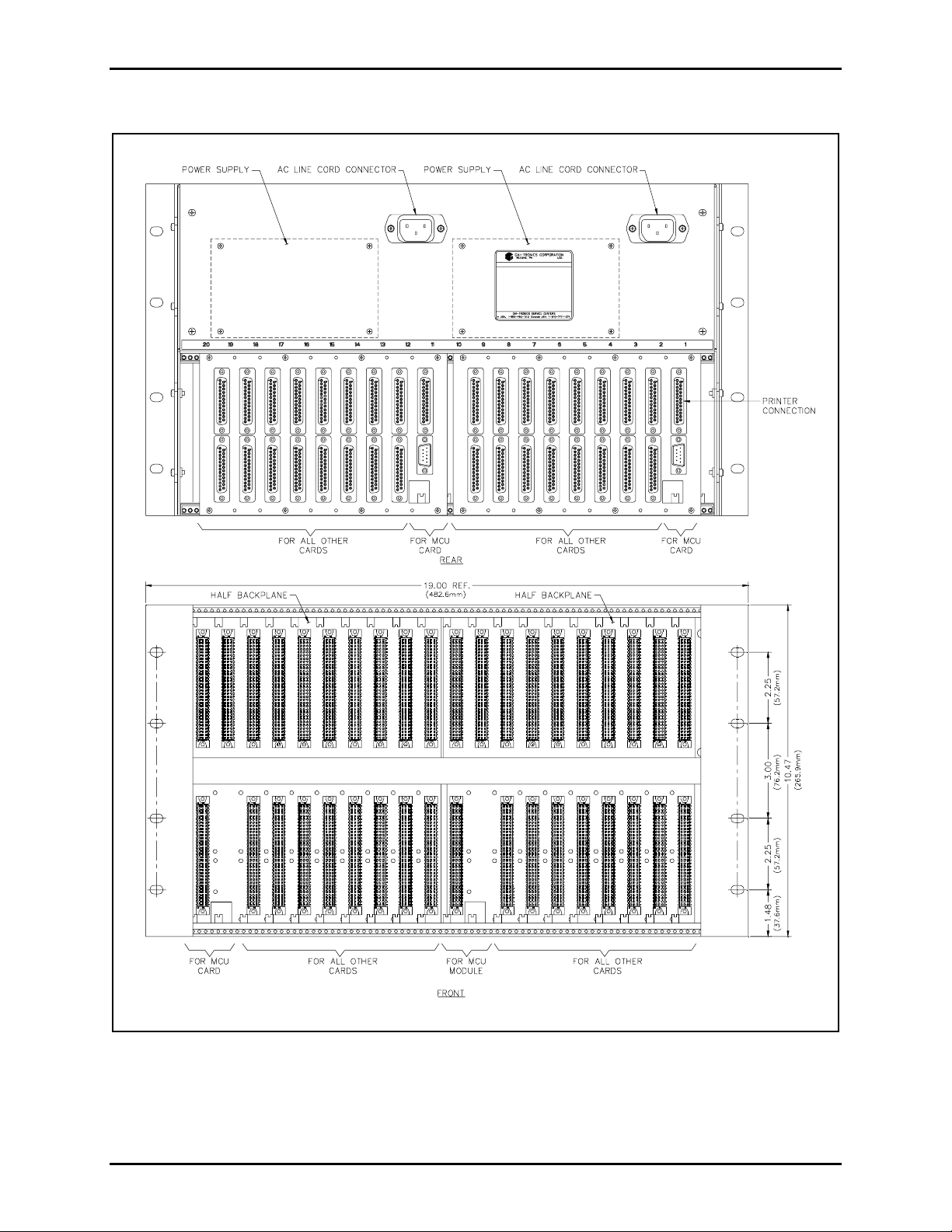
Figure 1. 10457-050 Re dund ant Backplane Card Rack Assembly
f:\standard ioms - current release\ 42004 ins t r. m anuals \ 42004-722l2a.doc
02/09
Page 3

Pub. 42004-722L2A
10457-050 REDUNDANT BACKPLANE CARD RACK ASSEMBLY Page 3 of 5
Installation
Direct questions about installation of this product to GAI-Tronics’ Field Service Department at 800-4921212 inside the USA or 610-777-1374 outside the USA.
Installation Guidelines
Please adhere to all warnings, safety, and operating instructions on the unit and in the installation
manual.
WARNING
• Disconnect powe r befor e inst alling o r re moving the plug-in card modules.
OTE: Removal and replacement of the card rack modules while the card rack has power
N
applied will
result in electrical damage to the respective module.
• Do not force plug-in cards into the backplane connectors on PCBAs.
• Secure plug-in cards with screws.
• Avoid servicing the unit during electrical storms.
• Do not t ouch uninsulated wire s.
• Do not remove power supply cover. There are no user-serviceable parts inside.
• Ensure that the installation is in accordance with local electrical codes.
Mounting
NOTE: Mounting ha rdware is not included and must be purcha sed separately.
1. Remove the 10457-050 Card Rack from its protective packing.
2. Position the card rack in the 19-inch EIA enclosure and secure the card ra ck with the appropriate
screws. When installed correctly, the power supply assembly is at the top rear of the enclosure.
The two VME-style backplanes on the card rack mate with the upper connector of each ca rd. The card’s
lower connect or mat es with the 64 -pin connect or on the lower backp l ane PCB As in the ca rd rack. Card
ra c k slots are nu mbered to aid in identifying the r es pective connect ions on the rear of the card ra c k.
Power
The power supplies are mounted on the rear of the 10457-050 Redundant Backplane Card Rack Assembly.
AC power is su pplied to the card rack via the two ac line cord c onnectors .
OTE: Two power cords (GAI-Tronics Part No. 61002-007) are included. They are packaged as part of
N
the 10457-050 Card Rack Assembly.
f:\standard ioms - current release\ 42004 ins t r. m anuals \ 42004-722l2a.doc
02/09
Page 4

Pub. 42004-722L2A
10457-050 REDUNDANT BACKPLANE CARD RACK ASSEMBLY Page 4 of 5
Maintenance
Troubleshooting
Problem Action
Power lights on the M CU
PCBA do not illuminate.
Plug-in cards do not opera te
in one of the slots.
1. Verify c onnection of a c power cord.
2. Verify ac p ower is app lied.
3. Verify the MCU is fully seated in the card rack.
4. Call for service of the applicable power supply.
1. Check sl ot with a known good plug-in card.
2. Call fo r servic e o f the bac k pla n e PCBA.
Specifications
Electrical
Power supply...................................................... Each supply is fused at 2 A, 250 V (not user-serviceable)
Input voltage................................................................................................................ 120 V ac/240 V ac
Total power consumed (card dependent)............................................................ 336 VA, 212 W maximum
Input frequency range................................................................................................................. 50/60 Hz
Input surge current (cold start)............................................................................Less than 40 A peak max.
Output current available: (max. not to exceed each power supply’s total output power):
(current based on c onvection cooling)
5 V / +/-12 V power supply .................................................................output 1 = 10 A @ +5 V dc
output 2 = 3 A @ +12 V dc
output 4 = 3 A @ -12 V dc
Total output power of each supply (50º C ambient temp. continuous)
Convection.................................................................................................................. 80 W max.
Conduc ted EMI ................................................................................................... Compliance to EN55022
AC input power connector (r ear) .................................................................................IEC 320-style, 3-pin
f:\standard ioms - current release\ 42004 ins t r. m anuals \ 42004-722l2a.doc
02/09
Page 5

Pub. 42004-722L2A
10457-050 REDUNDANT BACKPLANE CARD RACK ASSEMBLY Page 5 of 5
Environmental
Temperature operating....................................................................... +32° F to +122° F (0° C to +50° C)
Temperature storage....................................................................................................... -40° C to +85° C
Relative humidity...................................................................................................Non-conde nsing 5–85%
Mechanical
Unit dimensions................................. 10.47 H × 19.00 W × 13.88 D inches (265.9 × 482.6 × 352.55 mm)
Unit weight............................................................................................................................ 21 lbs. max.
Replacement Parts
Model No Description
40414-024 5 V / +/-12 V Power Supply
61002-007 AC Power Cord
f:\standard ioms - current release\ 42004 ins t r. m anuals \ 42004-722l2a.doc
02/09
Page 6

Warranty
Equipment. GAI-Tronics warrants for a period of one (1) year from the date of shipment, that any
GAI-Tronics equipment supplied hereunder shall be free of defects in material and workmanship, shall
comply with the then-current product specifications and product literature, and if applicable, shall be fit
for the purpose specified in the agreed-upon quotation or proposal document. If (a) Seller’s goods prove
to be defective in workmanship and/or material under normal and proper usage, or unfit for the purpose
specified and agreed upon, and (b) Buyer’s claim is made within the warranty period set forth above,
Buyer may return such goods to GAI-Tronics’ nearest depot repair facility, freight prepaid, at which time
they will be repaired or replaced, at Seller’s option, without charge to Buyer. Repair or replacement shall
be Buyer’s sole and exclusive remedy. The warranty period on any repaired or replacement equipment
shall be the greater of the ninety (90) day repair warranty or one (1) year from the date the original
equipment was shipped. In no event shall GAI-Tronics warranty obligations with respect to equipment
exceed 100% of the total cost of the equipment supplied hereunder. Buyer may also be entitled to the
manufacturer’s warranty on any third-party goods supplied by GAI-Tronics hereunder. The applicability
of any such third-party warranty will be determined by GAI-Tronics.
Services. Any services GAI-Tronics provides hereunder, whether directly or through subcontractors,
shall be performed in accordance with the standard of care with which such services are normally
provided in the industry. If the services fail to meet the applicable industry standard, GAI-Tronics will
re-perform such services at no cost to buyer to correct said deficiency to Company's satisfaction provided
any and all issues are identified prior to the demobilization of the Contractor’s personnel from the work
site. Re-performance of services shall be Buyer’s sole and exclusive remedy, and in no event shall GAITronics warranty obligations with respect to services exceed 100% of the total cost of the services
provided hereunder.
Warranty Periods. Every claim by Buyer alleging a defect in the goods and/or services provided
hereunder shall be deemed waived unless such claim is made in writing within the applicable warranty
periods as set forth above. Provided, however, that if the defect complained of is latent and not
discoverable within the above warranty periods, every claim arising on account of such latent defect shall
be deemed waived unless it is made in writing within a reasonable time after such latent defect is or
should have been discovered by Buyer.
Limitations / Exclusions. The warranties herein shall not apply to, and GAI-Tronics shall not be
responsible for, any damage to the goods or failure of the services supplied hereunder, to the extent
caused by Buyer’s neglect, failure to follow operational and maintenance procedures provided with the
equipment, or the use of technicians not specifically authorized by GAI-Tronics to maintain or service the
equipment. THE WARRANTIES AND REMEDIES CONTAINED HEREIN ARE IN LIEU OF AND
EXCLUDE ALL OTHER WARRANTIES AND REMEDIES, WHETHER EXPRESS OR IMPLIED BY
OPERATION OF LAW OR OTHERWISE, INCLUDING ANY WARRANTIES OF
MERCHANTABILITY OR FITNESS FOR A PARTICULAR PURPOSE.
Return Policy
If the equipment requires service, contact your Regional Service Center for a return authorization number
(RA#). Equipment should be shipped prepaid to GAI-Tronics with a return authorization number and a
purchase order number. If the equipment is under warranty, repairs or a replacement will be made in
accordance with the warranty policy set forth above. Please include a written explanation of all defects to
assist our technicians in their troubleshooting efforts.
Call 800-492-1212 (inside the USA) or 610-777-1374 (outside the USA) for help identifying the
Regional Service Center closest to you.
(Rev. 10/06)
 Loading...