

Page 1

Pub. 42003-237B
GAI-TRONICS® CORPORATION
A HUBBELL COMPANY
Intrinsically-Safe Microphone
Barrier Kit
Model 10438-101
Confidential ity Notice
This manual is provided solely as an operational, installation, and maintenance guide and contains
sensitive business and technical information that is confidential and proprietary to GAI-Tronics.
GAI-Tronics retains all intellectual property and other rights in or to the information contained herein,
and such information may only be used in connection with the operation of your GAI-Tronics product or
system. This manual may not be disclosed in any form, in whole or in part, directly or indirectly, to any
third party.
General Information
The Model 10438-101 Microphone Intrinsically-Safe Barrier Kit is designed for connection exclusively to
a GAI-Tronics Model 400-003 or 400-004 Rigcom Zone 1 Station in order to utilize a remote gooseneck
microphone in a hazardous area. The kit provides an intrinsically safe barrier. This allows the use of the
microphone at a location other than the station to which it is connected. The enclosure must be used in
applications where the microphone is mounted remotely from a station.
The Model 10438-101 Microphone Intrinsically-Safe Barrier Kit includes the following components:
Qty Description
1
No. 12801-001 Gooseneck Microphone Assembly with Mounting Flange
1
No. 69544-001 Enclosure with I.S. Barrier PCBA
Installation
This enclosure must be installed by trained, qualified and competent personnel. Installation must comply
with state and national regulations, as well as safety practices for this type of equipment.
CAUTION
must be installed in separate cables or in one cable having suitable insulation in accordance with the
requirements of BS EN 60079-25 / IEC 60079-25.
Where multiple circuits extend from the same piece of associated apparatus, they
CAUTION
approval listing in the “Specifications” section. Such installation may cause a safety hazard and
consequent injury or property damage.
GAI-Tronics Corporation 400 E. Wyomissing Ave. Mohnton, PA 19540 USA
Do not install this equipment in hazardous areas other than those indicated on the
610-777-1374 800-492-1212 Fax: 610-796-5954
V
ISIT WWW.GAI-TRONICS.COM FOR PRODUCT LITERATURE AND MANUALS
Page 2
Pub. 42003-237B
ODEL 10438-101 Intrinsically-Safe Microphone Barrier Kit Page 2 of 6
M
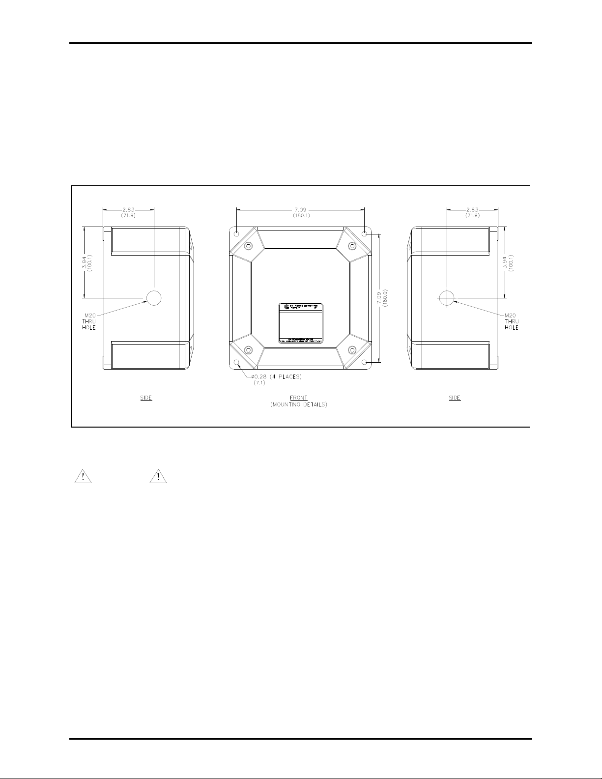
Mounting
Mount the enclosure using the four 0.28-inch (7-mm) diameter holes located on the mounting flanges
with 5/16-inch (M6) hardware. One M20 thru hole is provided on the left and right sides of the enclosure.
The suggested mounting height for the enclosure is 48 inches (1219 mm) to the center of the bottom
mounting holes of the enclosure.
Refer to Figure 1 for mounting dimensions.
Figure 1. Model 10438-101 Microphone I.S. Barrier Kit Mounting Details
WARNING
Insure proper grounding to protective earthing.
Do not disconnect equipment while energized.
After all wiring and cable connections have been completed, place the front cover on the rear enclosure,
being careful not to pinch any cables. Secure the front cover using the four screws and washers provided.
Torque the screws to 50 in-lbs (5.65 N-m).
e:\standard ioms - current release\42003 kit manuals\420 03-237b.doc
04/14
Page 3
Pub. 42003-237B
ODEL 10438-101 Intrinsically-Safe Microphone Barrier Kit Page 3 of 6
M
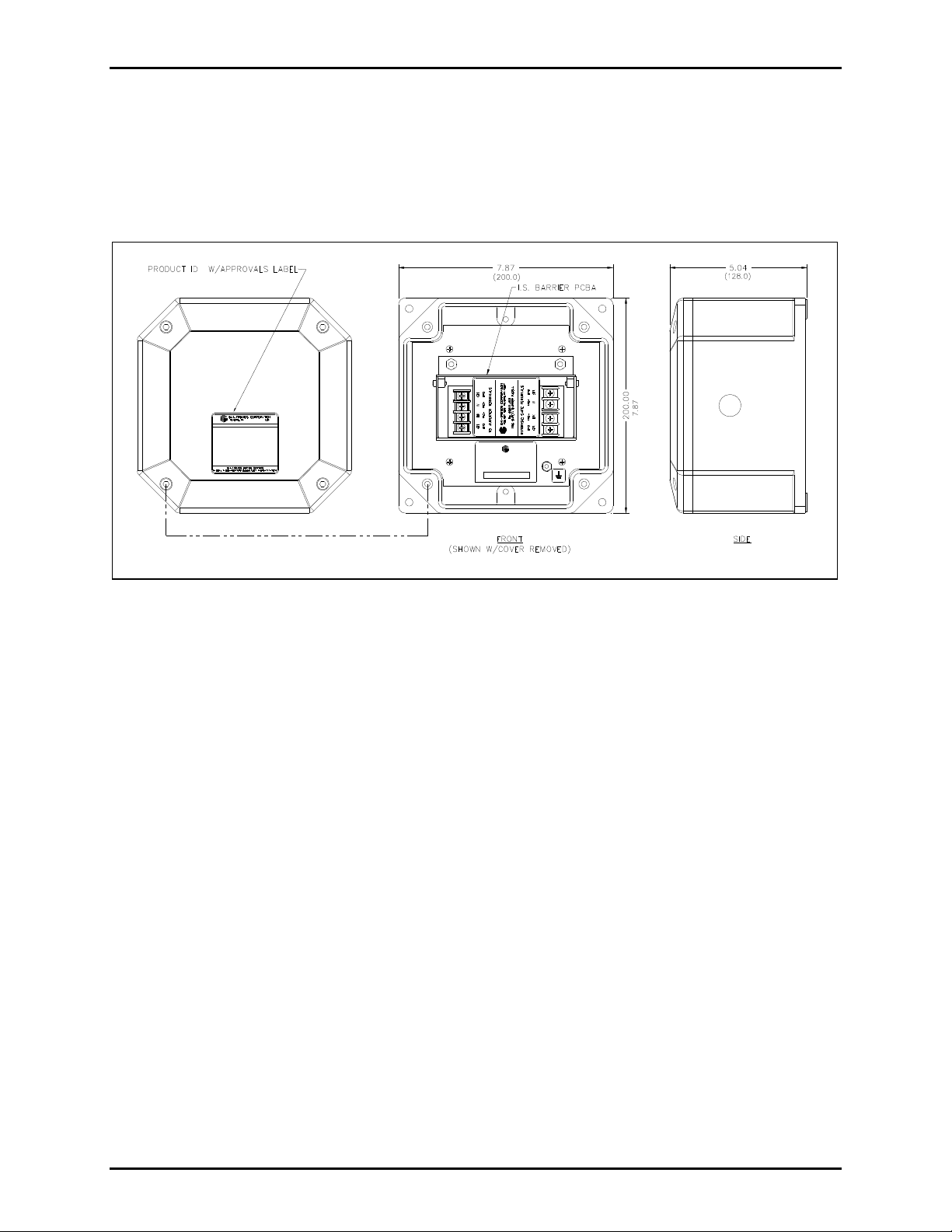
Enclosure Configuration
The Model 10438-101 I.S. Barrier Enclosure contains a single No 69544-001 PCBA where all customer
connections are made. Use one conductor (0.50–1.5 mm
2
) per screw terminal. Apply torque for wire
binding screws to 1.35 N-m. For wire clamps, apply torque to 2.36 N-m. All connections should be
properly lugged. The front cover of the enclosure contains all applicable approval labeling.
Figure 2. Model 10438-101 Microphone I.S. Barrier Outline Drawing
e:\standard ioms - current release\42003 kit manuals\420 03-237b.doc
04/14
Page 4

Pub. 42003-237B
ODEL 10438-101 Intrinsically-Safe Microphone Barrier Kit Page 4 of 6
M
Gooseneck Microphone
The microphone is mounted to a 19-inch gooseneck and has a supplied mounting flange. The gooseneck
microphone assembly has a 25-foot cord.
Figure 3. Model 12801-001 Microphone Assembly
e:\standard ioms - current release\42003 kit manuals\420 03-237b.doc
04/14
Figure 4.
Page 5

Pub. 42003-237B
ODEL 10438-101 Intrinsically-Safe Microphone Barrier Kit Page 5 of 6
M
Mounting the Gooseneck Microphone Assembly
Use the supplied mounting flange for mounting the gooseneck microphone assembly. A device box could
be used to mount the microphone assembly. The gooseneck should be mounted in accordance with
applicable electrical codes.
OTE: The path between the Model 400-003 or 400-004 Zone 1 RigCom Station and the Model 10438-
N
101 IS Barrier Enclosure must have type “d” flameproof cable gland. The path between the IS barrier
enclosure and the microphone must have a type “e” increased safety cable gland. Refer to Figure 5 for a
typical installation.
Figure 5. Typical Installation
e:\standard ioms - current release\42003 kit manuals\420 03-237b.doc
04/14
Page 6

Pub. 42003-237B
ODEL 10438-101 Intrinsically-Safe Microphone Barrier Kit Page 6 of 6
M
Specification s
Enclosure
Construction/finish ............................................................. Black, carbon loaded glass-reinforced polyester
Mounting ............................................................... Wall or column, four 0.28-inch (7-mm) mounting holes
Conduit entries ............................................................................. One M20 thru hole on two opposite sides
Dimensions .............................................. 7.87 H 7.87 W 5.04 D inches (200 H 200 W 128 D mm)
Shipping weight ..................................................................................................................... 6.5 lbs (2.9 kg)
Temperature range (operating and storage) .......................................... −4º F to +140º F (−20º C to +60º C)
Microphone
Element:
Type ................................................................................................................ Noise-canceling, dynamic
Impedance ................................................................................................................. 180 ohms, nominal
Construction/finish .................................................................................................................... Steel/chrome
Connections............................................................................................................................. Stripped wires
Dimensions ............................................................................................... 19 inches (482.6 mm) gooseneck
Supplied cable length .......................................................................................................................... 25 feet
Shipping weight ................................................................................................................ 1.25 lbs. (0.57 kg)
Approvals
CE Mark
Certificate No.
Notified Body ID No. 0539
UL International DEMKO A/S
Lyskear 8
DL-2730 Herlev
Denmark
DEMKO 12 ATEX 1116051 ..................................................................... II 2 G Ex e [ia] IIB + H
T6 Gb
2
IECEx UL 12.0012 ............................................................................................... Ex e [ia] IIB + H
T6 Gb
2
e:\standard ioms - current release\42003 kit manuals\420 03-237b.doc
04/14
Page 7

Warranty
Equipment. GAI-Tronics warrants for a period of one (1) year from the date of shipment, that any
GAI-Tronics equipment supplied hereunder shall be free of defects in material and workmanship, shall
comply with the then-current product specifications and product literature, and if applicable, shall be fit
for the purpose specified in the agreed-upon quotation or proposal document. If (a) Seller’s goods prove
to be defective in workmanship and/or material under normal and proper usage, or unfit for the purpose
specified and agreed upon, and (b) Buyer’s claim is made within the warranty period set forth above,
Buyer may return such goods to GAI-Tronics’ nearest depot repair facility, freight prepaid, at which time
they will be repaired or replaced, at Seller’s option, without charge to Buyer. Repair or replacement shall
be Buyer’s sole and exclusive remedy. The warranty period on any repaired or replacement equipment
shall be the greater of the ninety (90) day repair warranty or one (1) year from the date the original
equipment was shipped. In no event shall GAI-Tronics warranty obligations with respect to equipment
exceed 100% of the total cost of the equipment supplied hereunder. Buyer may also be entitled to the
manufacturer’s warranty on any third-party goods supplied by GAI-Tronics hereunder. The applicability
of any such third-party warranty will be determined by GAI-Tronics.
Services. Any services GAI-Tronics provides hereunder, whether directly or through subcontractors,
shall be performed in accordance with the standard of care with which such services are normally
provided in the industry. If the services fail to meet the applicable industry standard, GAI-Tronics will
re-perform such services at no cost to buyer to correct said deficiency to Company's satisfaction provided
any and all issues are identified prior to the demobilization of the Contractor’s personnel from the work
site. Re-performance of services shall be Buyer’s sole and exclusive remedy, and in no event shall GAITronics warranty obligations with respect to services exceed 100% of the total cost of the services
provided hereunder.
Warranty Periods. Every claim by Buyer alleging a defect in the goods and/or services provided
hereunder shall be deemed waived unless such claim is made in writing within the applicable warranty
periods as set forth above. Provided, however, that if the defect complained of is latent and not
discoverable within the above warranty periods, every claim arising on account of such latent defect shall
be deemed waived unless it is made in writing within a reasonable time after such latent defect is or
should have been discovered by Buyer.
Limitations / Exclusions. The warranties herein shall not apply to, and GAI-Tronics shall not be
responsible for, any damage to the goods or failure of the services supplied hereunder, to the extent
caused by Buyer’s neglect, failure to follow operational and maintenance procedures provided with the
equipment, or the use of technicians not specifically authorized by GAI-Tronics to maintain or service the
equipment. THE WARRANTIES AND REMEDIES CONTAINED HEREIN ARE IN LIEU OF AND
EXCLUDE ALL OTHER WARRANTIES AND REMEDIES, WHETHER EXPRESS OR IMPLIED BY
OPERATION OF LAW OR OTHERWISE, INCLUDING ANY WARRANTIES OF
MERCHANTABILITY OR FITNESS FOR A PARTICULAR PURPOSE.
Return Policy
If the equipment requires service, contact your Regional Service Center for a return authorization number
(RA#). Equipment should be shipped prepaid to GAI-Tronics with a return authorization number and a
purchase order number. If the equipment is under warranty, repairs or a replacement will be made in
accordance with the warranty policy set forth above. Please include a written explanation of all defects to
assist our technicians in their troubleshooting efforts.
Call 800-492-1212 (inside the USA) or 610-777-1374 (outside the USA) for help identifying the
Regional Service Center closest to you.
(Rev. 10/06)
 Loading...