

Page 1

Pub. 42006-011E
GAI-TRONICS® CORPORATION
A HUBBELL COMPANY
Field Maintenance Bulletin
Handset/Cord Replacement Procedure
Part No. 10108-107, 10108-10715 & 10108-10725
FOR MODEL 780 AND 7805 SERIES DIV. 1 HAZARDOUS AREA STATIONS
Confidentiality Notice
This manual is provided solely as an operational, installation, and maintenance guide and contains
sensitive business and technical information which is confidential and proprietary to GAI-Tronics. GAITronics retains all intellectual property and other rights in or to the information contained herein, and
such information may only be used in connection with the operation of your GAI-Tronics product or
system. This manual may not be disclosed in any form, in whole or in part, directly or indirectly, to any
third party.
T ools Required
7/16-inch hex socket or combination wrench
Phillips screwdriver
Pipe wrench or channel-lock pliers
Hammer
Nail set or hardened 1/8-inch diameter rod, approximately 4 inches long
Torque wrench
Liability Disclaimer
NOTICE: Follow all the steps in the procedure outlined below to ensure personnel safety, to avoid
equipment damage, and to maintain agency approvals.
GAI-Tronics Corporation 400 E. Wyomissing Ave. Mohnton, PA 19540 USA
610-777-1374 800-492-1212 Fax: 610-796-5954
ISIT WWW.GAI-TRONICS.COM FOR PRODUCT LITERATURE AND MANUALS
V
Page 2
Pub. 42006-011E
M
ODEL 780 AND 7805 SERIES DIV. 1 HAZARDOUS AREA HANDSET/CORD REPLACEMENT Page 2 of 3
Procedure
WARNING
OTE: The internal outer edge of the front cover is machined. Take precautions to ensure that the finish
N
Disconnect power before making any repairs to a hazardous area station.
is preserved. If damaged, the explosion-proof integrity can be lost.
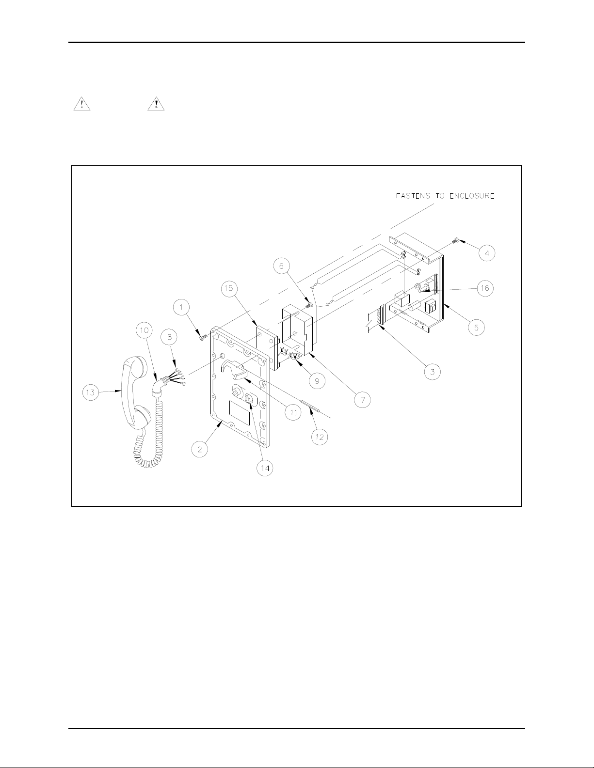
Figure 1. Replacement Handset with Cord and Amplifier Assembly
1. Turn off power.
2. Remove the 14 bolts (Ref. 1 typ.) from the front cover (Ref. 2) using a socket or a combination
wrench.
3. Lift off the front cover, and disconnect the flat ribbon cable (Ref. 3).
4. Remove the four screws (Ref. 4) that hold the amplifier assembly (Ref. 5) to the front cover (Ref. 2).
e:\standard ioms - current release\42006 field maint bulletins \42006-011e.doc
02/15
Page 3

Pub. 42006-011E
M
ODEL 780 AND 7805 SERIES DIV. 1 HAZARDOUS AREA HANDSET/CORD REPLACEMENT Page 3 of 3
5. Remove the four screws (Ref. 6 typ.) that hold the cover (Ref. 7) on the safety barrier (Ref. 15).
Remove the cover. Disconnect the four wires from the safety barrier to the amplifier assembly (Ref.
9) and the four handset cord wires (Ref. 8) from the safety barrier.
6. In order to rotate and remove the elbow (Ref. 10), the station handset hook (Ref. 11) must be
removed by driving out the metal retaining pin (Ref. 12).
OTE: The pin is tapered and can only be removed in one direction by driving it from the elbow side
N
of the hookswitch (when viewed from the front) using a nail set or 1/8-inch diameter rod.
7. Using a pipe wrench or channel-lock pliers, unscrew the elbow (Ref. 10) of the broken handset
assembly (Ref. 13).
8. Install the new handset assembly by feeding the wires on the elbow end of the handset assembly
through the threaded hole.
9. Secure the elbow (Ref. 10) to the front cover (Ref. 2) with a wrench. The handset elbow bushing
must be secured with 5 to 7 full threads. This is critical to the explosion-proof integrity. When
complete, the elbow should point downward.
10. Reconnect the four handset wires (Ref. 8) on the safety barrier inside the front cover to the terminals
labeled H
labeled A
ANDSET TERMINALS. Reconnect the amplifier assembly wires (Ref. 9) to the terminals
MPLIFIER TERMINALS. Ensure that the wire colors match the terminal markings.
11. Replace the safety barrier cover (Ref. 7) and secure with the four screws (Ref. 6 typ.).
12. Replace the amplifier assembly (Ref. 5) on the front cover, aligning the flat of the party line knob
shaft (Ref. 14) with the switch shaft (Ref. 16). Replace the four screws (Ref. 4 typ.).
13. Replace the handset hook and pin (Ref 11 and 12).
14. Carefully inspect the front cover’s machined edge for chips or gouges that could compromise
explosion-proof integrity.
15. Connect the flat ribbon cable (Ref. 3) and mount the station’s front cover (Ref. 2) onto the enclosure
and replace the 14 bolts (Ref. 1 typ.). Tighten each to a torque of 8 ft-lb.
16. Restore power and test for proper operation.
e:\standard ioms - current release\42006 field maint bulletins \42006-011e.doc
02/15
Page 4

Warranty
Equipment. GAI-Tronics warrants for a period of one (1) year from the date of shipment, that any
GAI-Tronics equipment supplied hereunder shall be free of defects in material and workmanship, shall
comply with the then-current product specifications and product literature, and if applicable, shall be fit
for the purpose specified in the agreed-upon quotation or proposal document. If (a) Seller’s goods prove
to be defective in workmanship and/or material under normal and proper usage, or unfit for the purpose
specified and agreed upon, and (b) Buyer’s claim is made within the warranty period set forth above,
Buyer may return such goods to GAI-Tronics’ nearest depot repair facility, freight prepaid, at which time
they will be repaired or replaced, at Seller’s option, without charge to Buyer. Repair or replacement shall
be Buyer’s sole and exclusive remedy. The warranty period on any repaired or replacement equipment
shall be the greater of the ninety (90) day repair warranty or one (1) year from the date the original
equipment was shipped. In no event shall GAI-Tronics warranty obligations with respect to equipment
exceed 100% of the total cost of the equipment supplied hereunder. Buyer may also be entitled to the
manufacturer’s warranty on any third-party goods supplied by GAI-Tronics hereunder. The applicability
of any such third-party warranty will be determined by GAI-Tronics.
Services. Any services GAI-Tronics provides hereunder, whether directly or through subcontractors,
shall be performed in accordance with the standard of care with which such services are normally
provided in the industry. If the services fail to meet the applicable industry standard, GAI-Tronics will
re-perform such services at no cost to buyer to correct said deficiency to Company's satisfaction provided
any and all issues are identified prior to the demobilization of the Contractor’s personnel from the work
site. Re-performance of services shall be Buyer’s sole and exclusive remedy, and in no event shall GAITronics warranty obligations with respect to services exceed 100% of the total cost of the services
provided hereunder.
Warranty Periods. Every claim by Buyer alleging a defect in the goods and/or services provided
hereunder shall be deemed waived unless such claim is made in writing within the applicable warranty
periods as set forth above. Provided, however, that if the defect complained of is latent and not
discoverable within the above warranty periods, every claim arising on account of such latent defect shall
be deemed waived unless it is made in writing within a reasonable time after such latent defect is or
should have been discovered by Buyer.
Limitations / Exclusions. The warranties herein shall not apply to, and GAI-Tronics shall not be
responsible for, any damage to the goods or failure of the services supplied hereunder, to the extent
caused by Buyer’s neglect, failure to follow operational and maintenance procedures provided with the
equipment, or the use of technicians not specifically authorized by GAI-Tronics to maintain or service the
equipment. THE WARRANTIES AND REMEDIES CONTAINED HEREIN ARE IN LIEU OF AND
EXCLUDE ALL OTHER WARRANTIES AND REMEDIES, WHETHER EXPRESS OR IMPLIED BY
OPERATION OF LAW OR OTHERWISE, INCLUDING ANY WARRANTIES OF
MERCHANTABILITY OR FITNESS FOR A PARTICULAR PURPOSE.
Return Policy
If the equipment requires service, contact your Regional Service Center for a return authorization number
(RA#). Equipment should be shipped prepaid to GAI-Tronics with a return authorization number and a
purchase order number. If the equipment is under warranty, repairs or a replacement will be made in
accordance with the warranty policy set forth above. Please include a written explanation of all defects to
assist our technicians in their troubleshooting efforts.
Call 800-492-1212 (inside the USA) or 610-777-1374 (outside the USA) for help identifying the
Regional Service Center closest to you.
(Rev. 10/06)
 Loading...