

Page 1
Pub. 42004-480B
GAI-TRONICS® CORPORATION
A HUBBELL COMPANY
Model 013-02-0095-002
Elemec3
Confidential ity Notice
This manual is provided solely as an operational, installation, and maintenance guide and contains
sensitive business and technical information that is confidential and proprietary to GAI-Tronics.
GAI-Tronics retains all intellectual property and other rights in or to the information contained herein,
and such information may only be used in connection with the operation of your GAI-Tronics product or
system. This manual may not be disclosed in any form, in whole or in part, directly or indirectly, to any
third party.
General Information
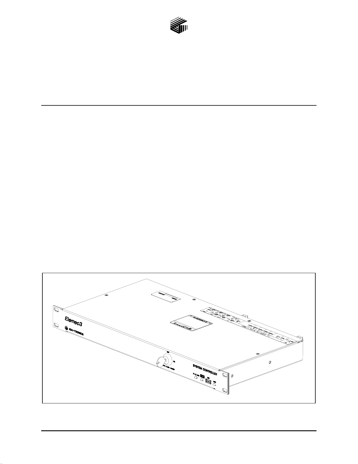
The Model 013-02-0095-002 Elemec3 System Controller is the central component of an Elemec3 central
amplifier system, processing all operations through its highly configurable system software. It is
designed to be installed in a standard (19-inch) Elemec3 system control cabinet.
System Controller
The Elemec3 System Controller provides continuous monitoring functions for up to 16 Microphone
Access Panels and sends/receives data from the Elemecplus Power Amplifiers, to provide complete high
integrity system monitoring, from microphone panel to loudspeaker. The integral software audio players
and the Elemec3 System Controller to amplifier audio paths are also monitored.
Figure 1. Elemec3 System Controller
GAI-Tronics Corporation 400 E. Wyomissing Ave. Mohnton, PA 19540 USA
610-777-1374 800-492-1212 Fax: 610-796-5954
V
ISIT WWW.GAI-TRONICS.COM FOR PRODUCT LITERATURE AND MANUALS
Page 2
Pub. 42004-480B
Model 013-02-0095-002 Elemec3 System Controller Page 2 of 11
The system provides two internal audio paths to enable simultaneous broadcast of audio to distinct output
zones. For ease of installation and maintenance all cabinet internal connections are on a plug/socket
basis.
The software control is designed to be as flexible as possible, and can easily be configured via the TCP/IP
network connection on the rear of the Elemec3 System Controller using the Elemec3 Console software
application. Hot standby amplifier control is provided so that a powered spare amplifier(s) is
automatically connected to the loudspeaker network of the failed amplifier(s).
®
PABX access and Page/Party
access are configured so that telephone/intercom inputs can be digitally
stored and replayed to completely eliminate the possibility of acoustic feedback between telephone/
intercom and local loudspeaker.
Up to 256 individually programmed relay outputs and 256 input contact points are available through the
LAN interface on the rear of the Elemec3 System Controller. Duplicate Elemec3 System Controller can
be used for additional redundancy. System status, including current audio activity, faults, input, output
and amplifier states, are monitored via the TCP/IP network connection using the Elemec3 Portal software
application.
The Elemec3 System Controller is exclusively designed for use in an Elemec3 system and is not intended
for use with other types of equipment.
Important Safety Instructions
1. Read these instructions.
2. Keep these instructions.
3. Heed all warnings.
4. Follow all instructions.
5. Do not use this apparatus near water.
6. Clean only with dry cloth.
7. Do not block any ventilation openings. Install in accordance with the manufacturer’s instructions.
8. Do not defeat the safety purpose of the polarized or grounding-type plug. A polarized plug has two
blades with one wider than the other. A grounding type plug has two blades and a third grounding
prong. The wide blade or the third prong is provided for your safety. If the provided plug does not fit
into your outlet, consult an electrician for replacement of the obsolete outlet.
e:\standard ioms - current release\42004 i nstr. manuals\4 2004-480b.doc
05/14
Page 3
Pub. 42004-480B
Model 013-02-0095-002 Elemec3 System Controller Page 3 of 11
9. Only use attachments/accessories specified by the manufacturer.
10. Use only with the cart, stand, tripod, bracket, or table specified by the manufacturer, or sold with the
apparatus. When a cart is used, use caution when moving the cart/apparatus combination to avoid
injury from tip-over.
11. Refer all servicing to qualified service personnel. Servicing is required when the apparatus has been
damaged in any way, such as power-supply cord or plug is damaged, liquid has been spilled or
objects have fallen into the apparatus, the apparatus has been exposed to rain or moisture, does not
operate normally, or has been dropped.
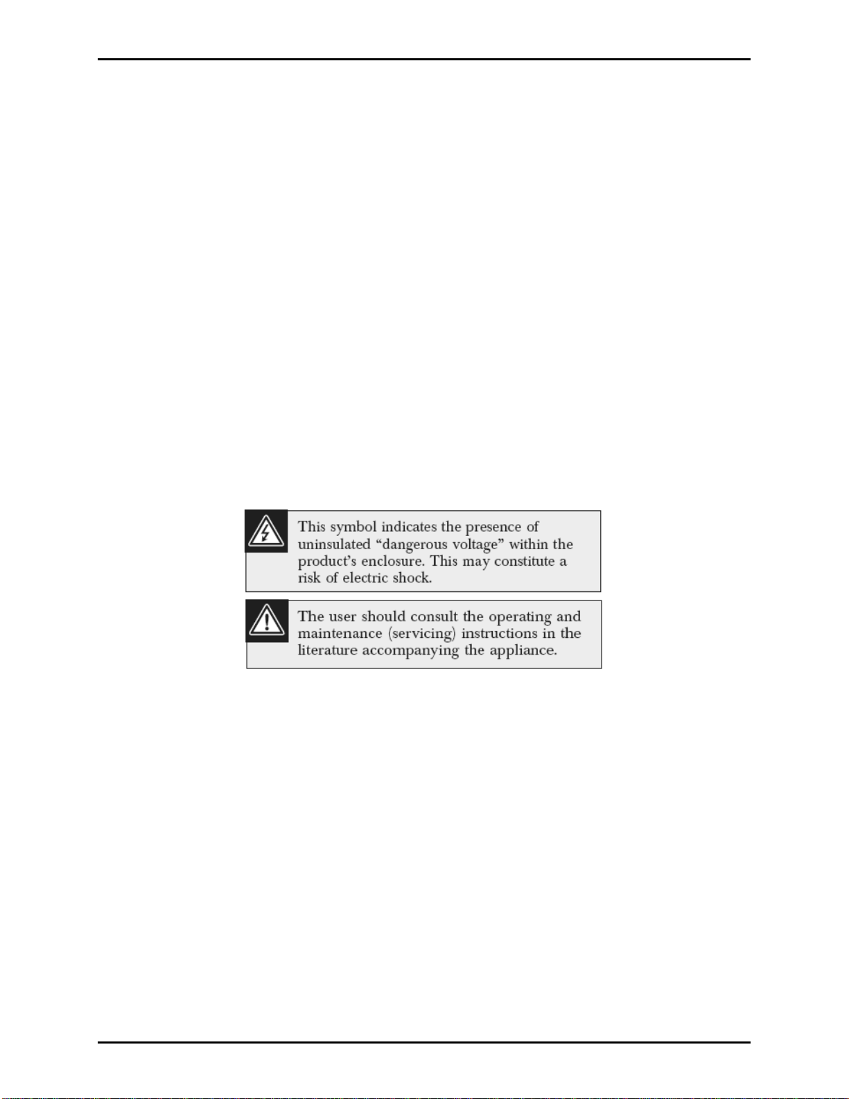
Front P anel Indicato rs & Control
The Elemec3 System Controller front panel is equipped with an alarm switch, three LED indicators and a
USB port (reserved for future use). The switch allows the operator to switch off and on specific inputs.
The LEDs indicate whether the page system is in use, the power is applied to the unit, and whether the
system is operating normally or has a fault condition.
Figure 2. Elemec3 System Controller – Front View
e:\standard ioms - current release\42004 i nstr. manuals\4 2004-480b.doc
05/14
Page 4
Pub. 42004-480B
Model 013-02-0095-002 Elemec3 System Controller Page 4 of 11
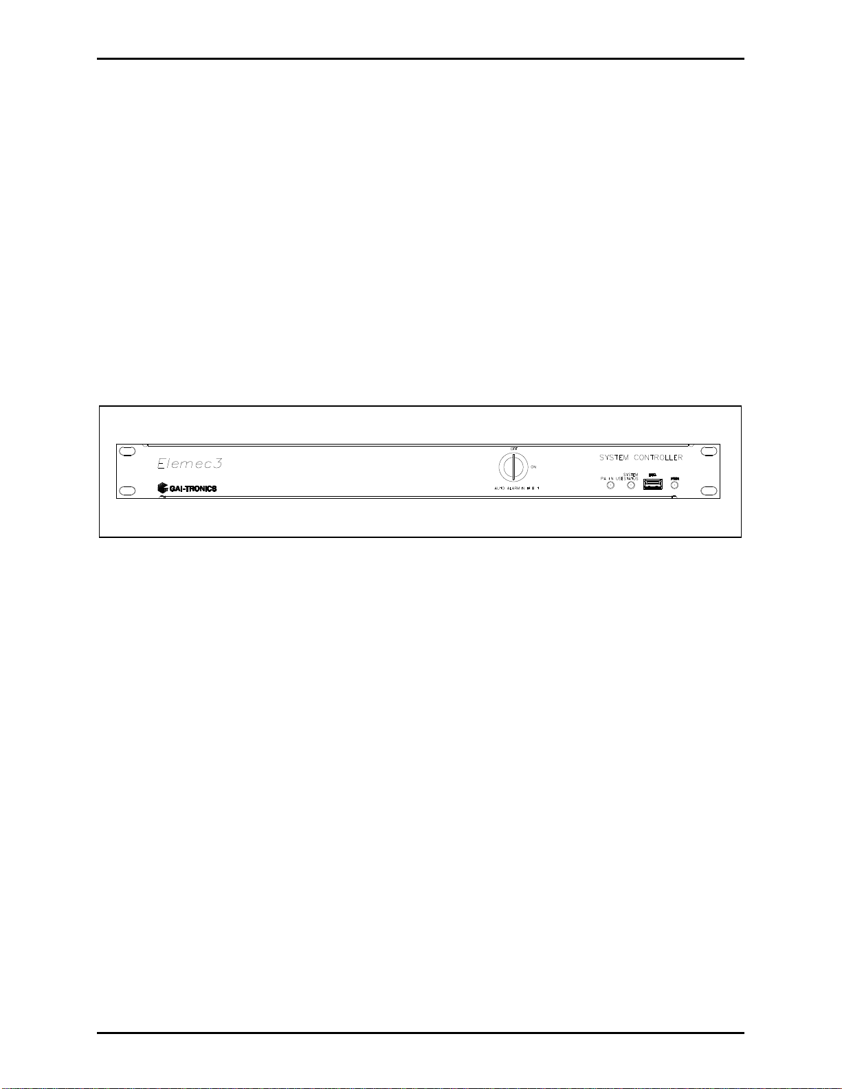
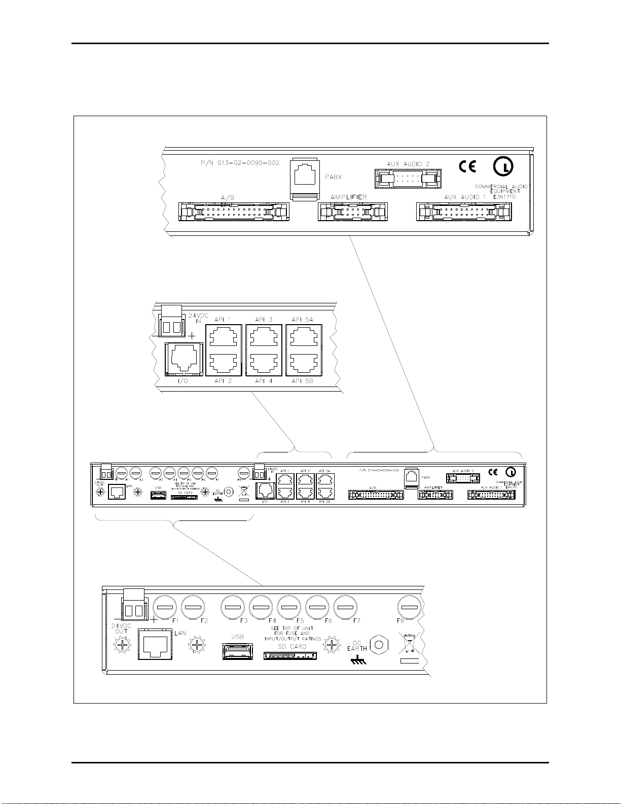
Rear P anel Connections
Refer to Figure 3. System connections are made to the rear of the Elemec3 System Controller.
U
USC
LISTED
Figure 3. Elemec3 System Controller – Rear View
LISTED
U
USC
e:\standard ioms - current release\42004 i nstr. manuals\4 2004-480b.doc
05/14
Page 5

Pub. 42004-480B
Model 013-02-0095-002 Elemec3 System Controller Page 5 of 11
Internal Connections
All internal connections are plug and socket connections.
Figure 4. Elemec3 System Controller – Internal Components – Top View
The main internal components are listed in Table 1 below:
Table 1. Elemec3 System Controller – Internal Components
Component Description
Digital PCBA Central processing unit and digital communications
Analog PCBA Provides speech recording and play-back to eliminate feedback.
Telephone Interface PCBA Interface from Elecmec3 System Controller to telephone system
Elemec3 Fuse PCBA See “Specification” section for description
The Elemec3 System Controller contains an internal clock that continually runs in the background. It is
has a battery back-up and the time is used as a time stamp on event logs when the status of the system
changes, such as an alarm event.
e:\standard ioms - current release\42004 i nstr. manuals\4 2004-480b.doc
05/14
Page 6

Pub. 42004-480B
Model 013-02-0095-002 Elemec3 System Controller Page 6 of 11
Installation
Mount the Elemec3 System Controller in the 19-inch rack using the supplied hardware.
The following is a discussion of the types of Elemec3 systems that can be configured. Refer to your
system manual for complete information.
Single System
In a single type system, the Elemec3 System Controller is typically installed in the top position of a
standard EIA 19-inch Elemec3 system equipment rack. It requires 1U (1.75 inches) of height.
Duplicate Sys tem
In a “duplicated” or redundant system, two Elemec3 System Controllers, designated as A and B, are
located in system racks at different location. In this type of system there are two sets of amplifiers (also
designated as A and B) with the two speaker loops run in different routes. If one Elemec3 System
Controller should fail, there would be a 50% loss of audible coverage.
Hot Standby (N+ 1) System
In a different type of redundant system, referred to as a Hot Standby (N+1), two Controllers, designated
as A and B, are located in the same cabinet and control a single set of amplifiers. The advantage to this
type of system is that there is no loss of coverage if one Elemec3 System Controller should fail.
e:\standard ioms - current release\42004 i nstr. manuals\4 2004-480b.doc
05/14
Page 7

Pub. 42004-480B
Model 013-02-0095-002 Elemec3 System Controller Page 7 of 11
Operation
NOTE: Each Elemec3 System Controller is custom-configured for a specific application via the Elemec3
software application. Please refer to your system manual for more information.
The Elemec3 System Controller front panel contains a rotary key switch, three LEDs and a USB port
(reserved for future use).
The key switch provides the capability to turn on or off previously configured inputs.
The LEDs operate in accordance with the following table:
Table 2. Front Panel LED Indications
LED Indication
PA IN USE
Green – Indicates the PA system is in use.
Off – Not in use
Green – Normal operation
Red – Fault condition – Refer to the display for additional information.
SYSTEM STATUS
Blinking Red – Fault acknowledged
Amber – Non-critical fault
Blue – Power is on.
PWR
Off – No power
The E3 Controller has been designed so that it can be monitored over an IP based data network either
locally or remotely. The loss of connection to the data network therefore constitutes a fault condition
which will be duly indicated by the SYSTEM
STATUS LED on the front of the Controller. For the
correct operation of the E3 Controller it should be connected at all times to a network.
e:\standard ioms - current release\42004 i nstr. manuals\4 2004-480b.doc
05/14
Page 8

Pub. 42004-480B
Model 013-02-0095-002 Elemec3 System Controller Page 8 of 11
Wi rin g
Connections
24VDC IN – Power is supplied to the Elemec3 System Controller via the 24VDC IN connector.
DC Earth – A green-yellow conductor shall be installed between the DC
EARTH terminal on the rear of
the unit to the Telecoms Earth Bar inside the cabinet.
LAN connection – The Elemec3 System Controller receives its initial programming and subsequent
updates and modifications via the LAN connection on the rear panel.
PABX connection – The interface to the telephone system is made via the PABX
connector on the rear
panel.
API 1–API 4 – Access panel interface connections. Provides the ability to connect to four access panel
termination PCBAs, which can each be connected to four user access panels with microphones, for a total
of 16 possible.
API 5A–API 5B – Reserved for future use.
SD Card – Reserved for use by a qualified technician.
USB – Reserved for use by a qualified technician.
I/O – Input/output signals that can be used for applications, such as the site Fire & Gas system,
monitoring systems, beacons, or loudspeakers.
24VDC Out – Power can be supplied to other components in the system cabinet.
e:\standard ioms - current release\42004 i nstr. manuals\4 2004-480b.doc
05/14
Page 9

Pub. 42004-480B
Model 013-02-0095-002 Elemec3 System Controller Page 9 of 11
Specification s
Electrical
Power supply requirements ................................................................................................. 24 V dc +/− 10%
Current consumed .............................................................................................................. 6.8 A (maximum)
Controller current consumed .......................................................................................... <0.76 A (unit itself)
Access Panel Interface Groups 1–4 .............................................................................. 460 mA (maximum)
Access Panel Interface Group 5B .................................................................................. 460 mA (maximum)
Input /output ........................................................................................................................1.4 A (maximum)
Auxiliary power output .....................................................................................................2.24 A (maximum)
Fuse Ratings (250 V)
(F2) Controller ....................................................................................................................................... T1 A
Additional fused power feeds provided for:
(F3) Group 1 Access Panel Interface cards ............................................................................. T500 mA*
(F4) Group 2 Access Panel Interface cards ............................................................................. T500 mA*
(F5) Group 3 Access Panel Interface cards ............................................................................. T500 mA*
(F6) Group 4 Access Panel Interface cards ............................................................................. T500 mA*
(F7) Group 5B Access Panel Interface cards .......................................................................... T500 mA*
(F8) Input / Output Cards ................................................................................................................... T1.6 A
(F1) Auxiliary Power Output ............................................................................................................. T2.5 A
*Power to access panels is fused to 100 mA on Access Panel Interface cards.
Access Panel Interfaces
Access panels per system .......................................................................................................... 16 maximum
One Type II Access Panel Interface card
Up to four Type I Access Panel Interface cards
Audio Pair
Operating level ................................................................................................... 2.2 Vpp maximum at 1 kHz
Input impedance ........................................................................................... 600 ohm +/− 50 ohms at 1 kHz
3-dB bandwidth ................................................................................. 200 Hz–20 kHz (input to zone output)
Data Pair
Operating Speed .............................................................................................................................. 57.6 kbps
Isolated RS-485 duplex data
Input / Output Interface
Inputs / outputs per system ..................................................................................................... 240 maximum
16-input / 16-output I/O cards per system ................................................................................ 15 maximum
16-input / 16-output I/O cards daisy chained on I/O Interface connector ................................... 5 maximum
N
OTE: Additional I/O cards can be powered via auxiliary power output.
Zone Audio Outputs
Isolation ....................................................................................................................................... >500 Vrms
Output Level ......................................................................... 2.2 Vpp maximum at 1 kHz into 17-ohm load
THD ......................................................................................... <1% at 1 kHz at 2.2 Vpp into 600-ohm load
S/N (Access Panel input) ........................................................................................ >60 dB (10 Hz–10 kHz)
e:\standard ioms - current release\42004 i nstr. manuals\4 2004-480b.doc
05/14
Page 10

Pub. 42004-480B
Model 013-02-0095-002 Elemec3 System Controller Page 10 of 11
Additional Facilities on Zone Outputs
Relay switching to A/B audio input
Page/Party
®
Audio Interface
Isolation................................................................................. 500 Vrms (input/output and output/output)
Input level ....................................................................................................... 1.5 Vrms maximum 1 kHz
3 dB bandwidth ............................................................................ 200 Hz–20 kHz (input to zone output)
Amplifier Data Links
Number ......................................................................... Two (one local amplifier, one remote amplifier)
Type ......................................................................................................................... RS-485 semi-duplex
Isolation............................................................................................................... 1500 Vrms (link – unit)
Un-isolated link-link and link-A/B data link
Operating speed.......................................................................................................................... 57.6 kbps
A/B Interlinks
Audio Input
Operating level .............................................................................................. 2.2 Vpp maximum at 1 kHz
Input impedance ...................................................................................................... >60 k-ohms at 1 kHz
3-dB bandwidth ............................................................................ 200 Hz–20 kHz (input to zone output)
Data Link
Type .......................................................................................................................... RS-485 fully duplex
Isolation.................................................................................................................. 2500 Vrms (link unit)
Operating speed.......................................................................................................................... 57.6 kbps
Auxiliary Audio Inputs
Audio Input
Operating level .............................................................................................. 2.2 Vpp maximum at 1 kHz
Input impedance ...................................................................................................... >80 k-ohms at 1 kHz
3-dB bandwidth ............................................................................ 200 Hz–20 kHz (input to zone output)
Aux 1 Control Input
Type ..................................................................................................... Normally open pulled-up contact
O/C voltage .................................................................................................................... 3.3 V dc nominal
Current source ............................................................................................................. 300 uA +/−100 uA
Auxiliary Audio Output
Audio Output
Output level .................................................................... 2.2 Vpp maximum at 1 kHz into 600-ohm load
3-dB bandwidth ................................................................................................................ 200 Hz–20 kHz
Monitor Au dio Output
Audio Output
Output level .................................................................... 2.2 Vpp maximum at 1 kHz into 600-ohm load
3-dB bandwidth ................................................................................................................ 200 Hz–20 kHz
e:\standard ioms - current release\42004 i nstr. manuals\4 2004-480b.doc
05/14
Page 11

Pub. 42004-480B
Model 013-02-0095-002 Elemec3 System Controller Page 11 of 11
Event Audio Outputs
Audio Output
Output Level .................................................................. 2.2 Vpp maximum at 1 kHz into 600-ohm load
3-dB bandwidth ................................................................................................................ 200 Hz–20 kHz
Key switch ................................................................................................................... Auto alarm inhibit
Status LEDs ................................................................................................................................. Unit Power
PA In Use
System Status
Status Monitor ....................................................................................................................... Elemec3 Portal
Ports
Ethernet Port ................................................................................................................... RJ45 Connector
USB Device Port - Front ............................................................................................................... Type A
USB Device Port - Rear ................................................................................................................ Type A
O/C Voltage ........................................................................................................................ 5.1 V dc nominal
Current .......................................................................................... 500 mA (maximum) +/−10 mA per port
Memory card type .............................................................................................................. SD Memory Card
Environmental
Operating temperature range .................................................................................................. 20
o
C to +50o C
Relative humidity .................................................................................................................................... 95%
Mechanical
Unit dimensions ............................................ 482.6 W 43.7 H 226.3 D mm (19.0 1.72 8.91 inches)
Unit weight............................................................................................................................ 2.4 kg (5.2 lbs.)
Approval
CE Mark
NRTL ..................................................................................................................................... UL/CSA 60065
e:\standard ioms - current release\42004 i nstr. manuals\4 2004-480b.doc
05/14
 Loading...