

Page 1
Operation, Maintenance and Installation Manual
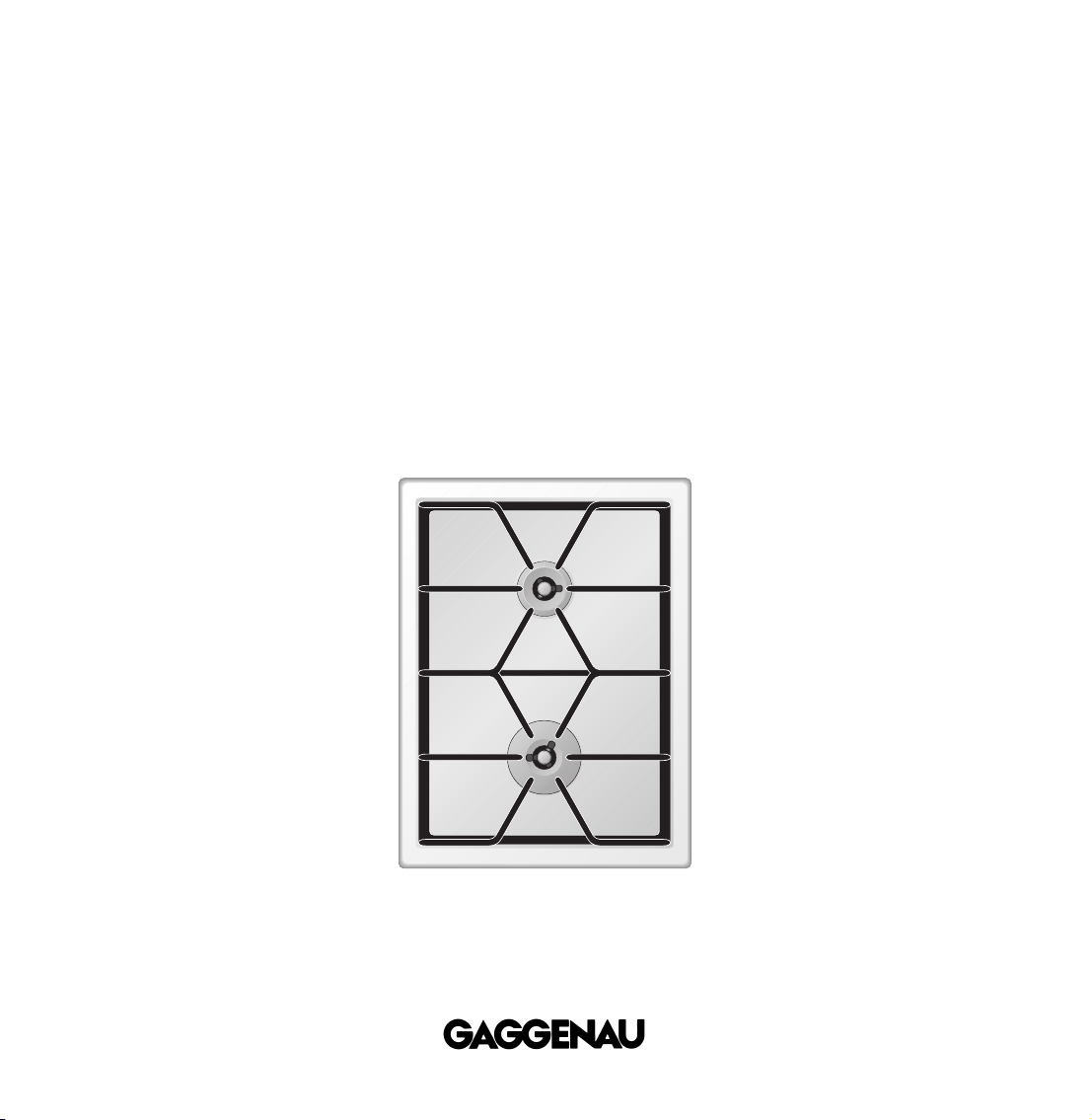
VG 421 AU
Built-in gas hob
Page 2

1
VG 421 AU
FOR YOUR SAFETY Page 2
Warnings Page 3
1. Important Notes Page 5-6
For Your Safety Page 5
Operating for the First Time Page 5
About Use Page 6
2. Features Page 7
Features of the Appliance Page 7
Control Knobs Page 7
Burner Parts Page 7
3. Operating Principle Page 8
4. Operation Page 9
5. Settings Table Page 10
6. Cookware Recommendations Page 11
7. Cleaning and Care Page 12-13
8. Maintenance Page 14
9. Trouble Shooting Page 15
10. Technical Data / Nozzle Table Page 16-17
11. Installation Instructions Page 18-26
Important Notes on Installation Page 18
Connecting the Appliance Page 19
Preparing the Cabinet Page 20
Installing the Hob Page 21
Installing the Spindles Page 22-23
Nozzle Replacement Page 24-25
Fitting the Appliance Cover Page 26
Page 3
2
FOR YOUR SAFETY
WARNING: If the information in this manual is not followed exactly,
a fire or explosion may result causing property damage, personal
injury or death.
Do not store articles on or against this appliance.
Do not use or store flammable materials near this appliance.
Do not spray aerosols in the vicinity of this appliance while it is in
operation.
WHAT TO DO IF YOU SMELL GAS:
– Do not try to light any appliance.
– Do not touch any electrical switch;
do not use any phone in your building.
– Immediately call your gas supplier from a neighbor’s phone.
Follow the gas supplier’s instructions.
– If you cannot reach your gas supplier, call the fire department.
Installation and service must be performed by an authorised
person.
Where this appliance is installed in a marine craft or in caravans,
for safety reasons it shall not
be used as a space heater.
This appliance is not intended for the use of young children or
infirm persons without supervision. Young children should be
supervised to ensure they do not play with this appliance.
Page 4

1. Do not allow the flame to extend beyond the
edge of the cooking utensil. This instruction is
based on safety considerations.
2. Do not forget that the unit becomes hot when in
use. Common sense is important. Just because
the flame is out, it does not mean parts still
cannot be hot.
3. This appliance shall not be used for space
heating. This instruction is based on safety
considerations.
4. Be sure to disconnect the electrical supply
before disassembly of the appliance.
5. Keep the appliance area clear and free from
combustible materials, gasoline and other
flammable vapors and liquids.
6. Do not obstruct the flow of combustion and
ventilation air.
7. Do not install the appliance under a suspended
cabinet. For installation under a vapour extractor
hood, a minimum clearance of 650 mm from the
top edge of the pot stand to the bottom edge of
the extractor hood must be observed.
8. The gas pressure regulator supplied with the
appliance must be installed in line with the gas
pipe.
9. The appliance and its individual shutoff valve
must be disconnected from the gas supply
piping system during any pressure testing of the
system at test pressures in excess of 3.5 kPa
(1/2 psig). The appliance must be isolated from
the gas supply piping system by closing its
individual manual shutoff valve during any
pressure testing of the gas supply piping system
at test pressures equal to or less than 3.5 kPa
(1/2 psig).
10.Important:
When using a very large pot, leave a gap of at
least 50 mm (2") to avoid damaging any parts in
counter top wood, plastic or other non-heatresistant materials. Never leave oil or hot fat
unattended.
Note:
To avoid jeopardising the electrical safety of the
appliance, it is forbidden to use high-pressure or
steam jet cleaning devices.
Note:
The name plate is attached to the bottom of the unit
and to the inside of the housing.
This appliance shall be installed in accordance with
the manufacturer’s installation instructions, local
gas fitting regulations, municipal building codes,
electrical wiring regulations, the Installation Code
for gas burning appliances, AS 5601 and any other
statutory regulation. Refer to the AGA Installation
Code for pipe sizing details.
3
Warnings
Page 5
4
Congratulations on buying your new
“Vario” appliance.
Before switching your appliance on for the first
time, we would like you to familiarize yourself with
your new appliance. In this manual you will find
important notes on safety and operation. These
will serve to ensure your personal safety and the
lasting value of your appliance. Keep the
instruction manual near your appliance for further
reference.
You will find notes on Page 5 that you ought to
observe before operating the appliance for the
first time.
The chapters entitled “Features" and “Operation"
tell you all about what your appliance can do and
how you operate it.
The chapter entitled “Cleaning and Care" gives
tips on how to keep your appliance looking good.
And now we wish you lots of fun cooking.
Page 6

5
For Your Safety
You must not operate the appliance if it is damaged.
When connecting electrical appliances in the proxi-
mity of the appliance, make sure that connecting
leads do not come into contact with hot cooking
surfaces!
As the user, you yourself are responsible for
maintenance and proper use in the household.
Only ever operate the appliance under supervision.
Do not operate the appliance without pots and pans
placed on it. Make sure that all the burner parts are
correctly fitted.
Caution: the appliance heats up during operation.
Keep children away.
Do not clean the appliance with a steam cleaning
apparatus or with water pressure - risk of short-
circuits!
Isolate the appliance from the mains during every
maintenance operation. To do this, remove the
mains plug or switch off the corresponding
household fuse. Close the gas supply.
Repairs must be carried out by an authorised
person.
No warranty claims can be lodged for any damage
resulting from failure to observe these instructions.
Observe caution with oils and fats. They may
overheat and burn easily.
Foodstuffs that are prepared in fat and oil must only
be prepared under constant supervision!
Technical modifications reserved.
Operating for the First Time
Remove the packaging from the appliance and
dispose of it according to local regulations. Be
careful to remove all accessories from the
packaging. Keep packaging elements and plastic
bags away from children.
Check the appliance for transport damage before
installing it.
The appliance must be installed and connected by
an authorised specialist before operation. The
installation must conform with all current regulations
of the gas supply companies and the regional
construction regulations.
Turn all control knobs to the OFF position before
connecting the appliance to the power supply.
The serial number of the appliance can be found on
the quality control slip which is included with these
instructions. This quality control slip should be kept,
for guarantee reasons, together with your operating
and assembly instructions.
Read through these instructions carefully before
operating your appliance for the first time.
Thoroughly clean the appliance and accessories
before using them for the first time. This will
eliminate any 'newness’ smells and soiling (see
chapter “Cleaning and Care”).
1. Important Notes
Page 7

6
About Use
The appliance is intended solely for use in the
household and must not be put to any other uses.
Use the appliance to prepare meals only. It must not
be used to heat up the room in which it is installed.!
Use of a gas hob generates heat and humidity in
the room where it is installed. This is why attention
must be paid to good kitchen ventilation.
The natural ventilation openings must be kept
unobstructed. Prolonged use of the appliance
with several or all rings may call for additional
ventilation such as opening a window or a door,
or stronger air extraction by an extractor hood.
To guarantee good combustion, the room in
which the appliance is installed must have
a minimum volume of 20 m
3
and must possess
a door that opens outdoors or a window that
can be opened.
Keep the ventilation openings at the back of the
appliance free at all times.
Only use the burners after placing pots and
pans on them. Do not heat up any empty pots
or pans; this may result in a build-up of heat. Use
pots and pans with thicker bottoms because heat
distribution is particularly improved in the low
setting. Using pots and pans which are adapted to
the burner size increases the efficiency of the heat
from the gas flame, thereby reducing power costs.
It is not permitted to use roasting pans, frying pans
or grill stones heated simultaneously by several
burners because the resulting heat build-up may
damage the appliance.
Pots with a diameter of less than 90 mm or more
than 280 mm should not be used. When using large
pots, pay attention to keeping to a minimum
distance of 50 mm between the cooking vessel and
combustible surroundings.
In the event of a spill or boil over the burner ring
and head may need to be removed and cleaned.
Perform when burner is cold. For identification of
burner ring and head see page 7.
Switch the burners to the low setting whenever you
remove pots or pans briefly. In this way, you reduce
the risk of burns when working next to naked
flames; you also save gas and reduce pollution.
Whenever the gas hob is fitted under an extractor
hood, always cover the rings with pots or pans.
Otherwise, parts of the extractor hood may become
damaged by the extreme heat development or
grease residues in the filter may ignite.
Ensure an adequate supply of air when using
an extractor hood operating in the extraction
mode !
The appliance cannot be used during a power
failure.
In the event of malfunctions, please inform your
specialist dealer or your nearest Gaggenau aftersales service.
Page 8
7
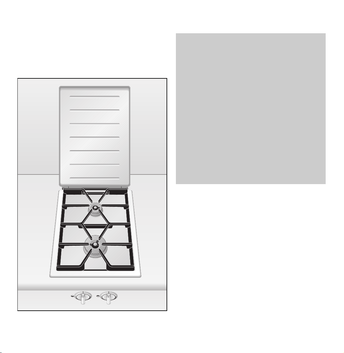
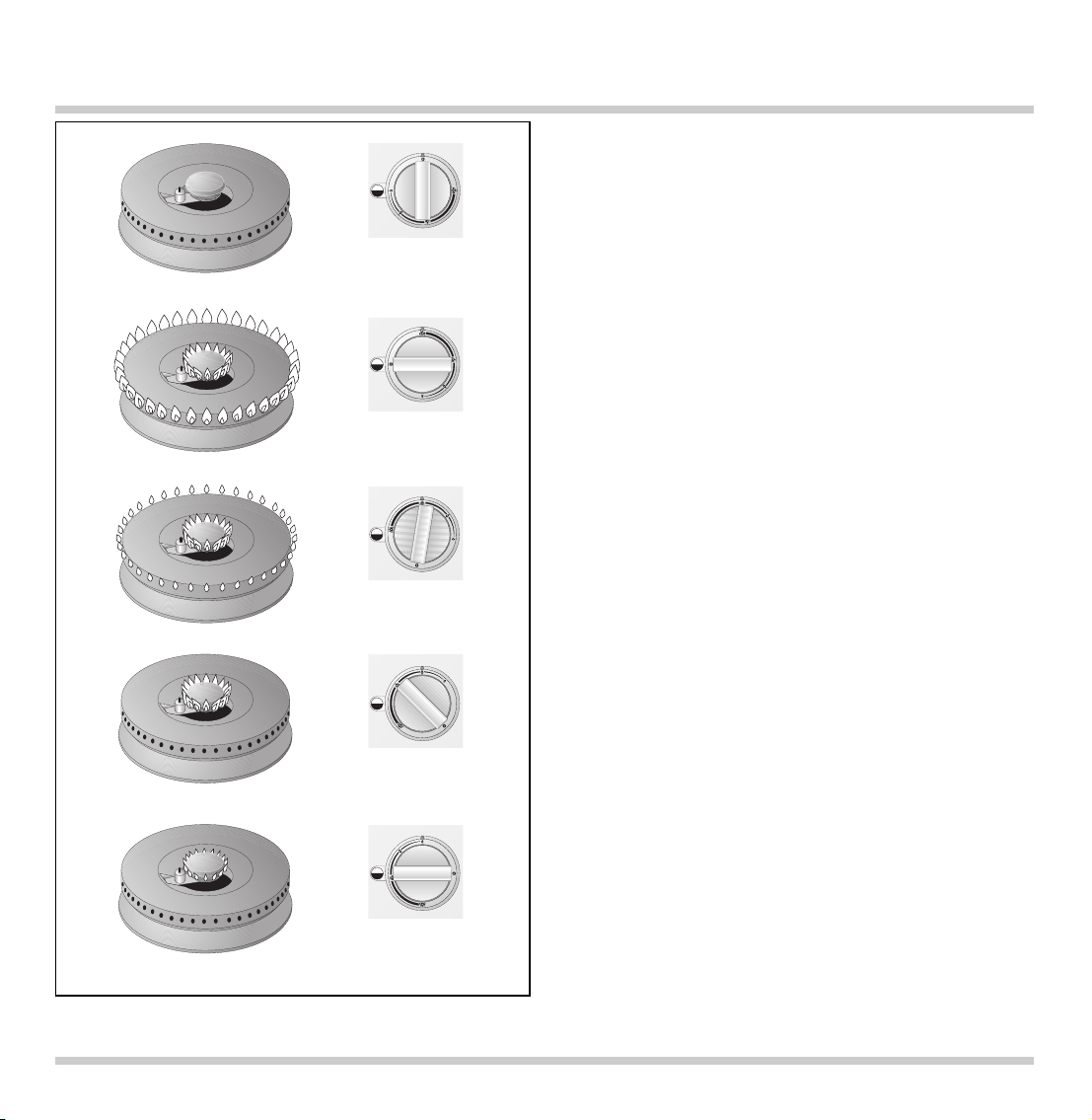
Features of the Appliance
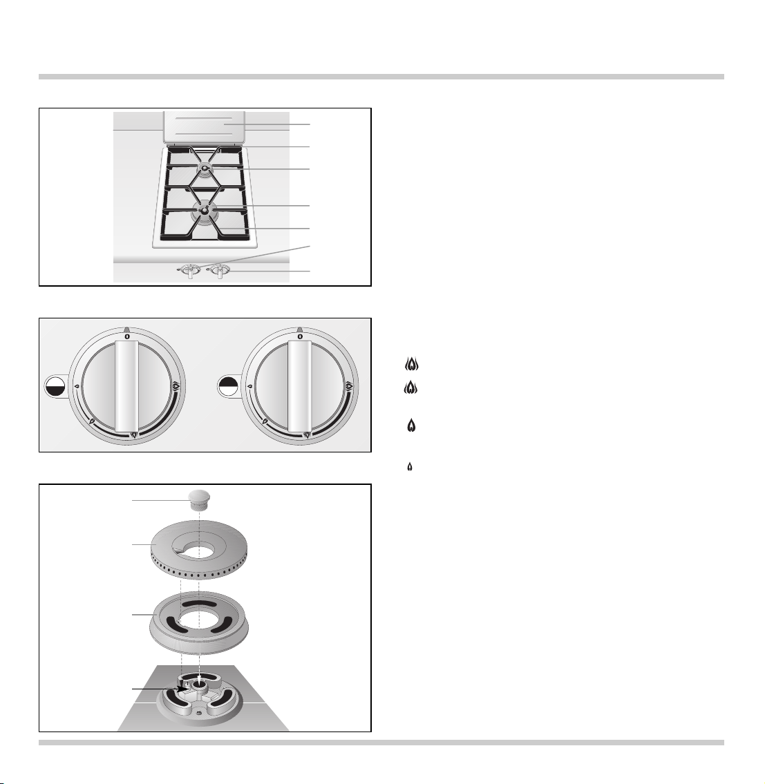
Control Knobs
Burner Parts
1 Appliance cover
2 Ventilation openings
3 Normal burner
4 Large burner
5 Pot grid
6 Control knob for front cooking zone
7 Control knob for rear cooking zone
Flame setting:
0 OFF
High setting of outer and inner flame ring
Low setting of outer flame ring
High setting of inner flame ring
Outer flame ring off
High setting of inner flame ring
Outer flame ring off
Low setting of inner flame ring
1 Burner head cover
2 Burner ring
3 Burner head
4 Electrode for automatic ignition,
flame detection and flame control
You can order the following special accessory:
VV 400-000 Connecting trim
SV 402-090 Spindle extension up to 140 mm
SV 402-205 Spindle extension up to 300 mm
LS 330-000 Air baffle for installation next to
VL 430/431
2. Features
2
1
3
4
1
2
3
4
5
6
7
Page 9
8
3. Operating Principle
The appliance features one-hand operation, flame
detection and automatic re-ignition. The ignition is
activated when the control knob is turned.
Should the flame go out during operation, the
appliance will automatically re-ignite the burner.
During a disturbance, the appliance will cut off
the gas supply as a safety measure, to prevent
unburned gas escaping.
The flame setting is infinitely variable between high
and low.
The total rated thermal load amounts to:
20.5 MJ (5.69 kW) for natural gas
22.5 MJ (6.16 kW) for propane gas
The specified rated load is defined by installation
of the fixed nozzles.
The gas hob is converted to a different gas
type by nozzle replacement (full and low-burning
nozzles) (see nozzle table on page 16-17).
Off
High
Low
Page 10

9
Switching on
• Place a suitable pot or a pan on the corresponding
cooking position.
• Press down the control knob for the cooking
position and turn it to the required position
between the and symbols. The burner ignites
automatically.
• When using large pots or pans you should ignite
the burner in the low position.
• Every time the gas hob is switched on, the
electronics run an auto test. The electrode fires
and the burner ignites after a few seconds.
• When being switched on, a short sound may be
heard when the electronic of the gas hob opens
the gas supply valve. This is a normal condition.
The flame size can be set continuously between full
and low by slowly turning the control knob.
Should the flame go out during operation (e.g.
because of a draught), the appliance will
automatically re-ignite the burner.
Should the re-ignition be unsuccessful (e.g. burner
is soiled by spilled over food or liquid), the gas
supply is switched off automatically and a signal is
sounded. Turn the control knob to the OFF position.
After the appliance has cooled down sufficiently,
check if all the burner parts have been assembled
correctly. Check if the burner or the electrode have
been soiled.
Switching off
Fully turn the control knob to the OFF position.
The electronics of the appliance switch the gas
supply off.
4. Operation
Only light a burner if all burner parts are dry, and
assembled correctly. Otherwise, malfunctions may
occur or the appliance may switch off.
Page 11

10
5. Settings Table
Cooking Cooking method Examples
level
High Boiling Water
Searing Meat
Heating Fat, liquids
Boiling Soup, sauce
Blanching Vegetables
Roasting Meat, fish, potatoes
From Browning Flour, onions
Roasting Almonds, breadcrumbs
Baking Pancakes, egg dishes
to Boiling in open pot Liquids
Simmering in open pot Dumplings, sausages, soup garnish,
meat stock, poached eggs
Simmering Sweet sauces
From Boiling with closed lid Pasta, soup, sauces
Steaming Vegetables, potatoes, fish
to Stewing Vegetables, fruit, fish
Braising Goulash, rolled beef steaks, roasts,
vegetables
Low Thawing Frozen foods
Slow cooking Rice, pulses
Reheating Soup, casserole, vegetables in a sauce
Switch to the high setting in order to reach the required temperature quickly. Then switch back to a lower
setting.
The values given above must be looked upon as recommended values. The heat required depends not
only on the type and condition of the food, but also the size and contents of the pot.
Due to the high performance of the cooktop, fat and oil will heat up quickly. Never leave the cooktop
unattended, fat can ignite, food can burn.
Page 12

Pots with a diameter of less than 90 mm or more
than 280 mm should not be used. When using large
pots, pay attention to keeping to a minimum
distance of 50 mm between the cooking vessel and
combustible surroundings.
When buying pots, pay attention to the fact
that the manufacturer frequently specifies the top
pot diameter, which is generally larger than the
diameter of the base.
Observe the manufacturer’s specifications! Use
cooking utensils that the manufacturer states as
being “suitable for gas". Use pots with heat resistant
handles.
Use pots and pans with a thick base, because heat
distribution is particularly improved in the low
setting. Using the correct size of pots and pans for
the burner ensures improved cooking performance
and energy efficiency.
To ensure an even distribution of heat, center the
pot above the burner. The flames should be
covered by the pot base.
Place the pot or pan securely and level on the pot
grid. Turn the pan handle to the side, it should not
point to the front. In order to guarantee a secure
position on the pot grid, the pot base should be flat
and not warped or dented.
Placing a fitting lid on the pot will shorten cooking
times. Through a glass lid you can watch the
cooking progress without having to take the lid off.
11
6. Cookware Recommendations
VG 421 Recommended Minimum
pot diameter pot diameter
Normal Burner 200 - 240 mm 90 mm
Large Burner 240 - 280 mm 90 mm
Page 13

12
Keep the ventilation openings on the rear of the
appliance clean. Do not block the ventilation
openings.
The burners (burner head cover, burner ring and
burner head) will change their color during
operation and become darker. This change in color
will not influence the use-value.
Please thoroughly clean the appliance before
operating it for the first time and after every use.
Do not use scouring agents, abrasives or chemically
aggressive cleaners (for example oven cleaner)!
Do not use any nitro polishing agents for cleaning!
Do not use any abrasive sponges either.
Before cleaning, please wait until the cooktop
has cooled to hand-warm !
• First lift the pot grid with both hands (be careful
not to scratch the base).
• Remove the burner head cover, the burner
rings and the burner head.
• Important! Only clean the burner parts when
cold!
• Soak burnt-in remainders in a little water and
detergent. This loosens even the most stubborn of
soiling. Do not use any abrasive agents and
abrasive sponges.
• Only use very little water to clean your cooktop.
Be careful that no water enters the burner base.
• As the result of heat development, slight discoloration can appear on the stainless steel
surface. Do not attempt to scrape away such
discoloration. This damages the surface.
Distribute stainless steel care agents uniformly
and thinly on the hob. This will ensure an even
surface and will keep your hob in a good
condition for a long period of time.
• Make sure the burner parts are dry before
assembly. Only operate the appliance with all
parts dry. Damp burner parts will cause
malfunctions when igniting or unstable flames.
• When assembling the burner parts, make sure
that the burner ring and burner head are placed
in such a way that the locking lugs fit in the
corresponding recesses.
7. Cleaning and Care
Note: to avoid jeopardising the electrical safety of
the appliance, do not use high-pressure or steam
jet cleaning devices – risk of short circuits!
Caution, risk of burns! Before cleaning,
please wait until the cooktop has cooled to
hand-warm. Never switch on the cooktop
while cleaning.
burner head
cover
burner ring
burner head
electrode
burner base
burner assembly
Page 14

13
Part / Material Suggested Cleaning Procedure Important Reminders
Pot Grid Take pot grids off for cleaning. Do not clean in a dishwasher.
(enamel on Soak in sink. Soak burnt-in remainders in sink.
cast iron) Clean with detergent and brush. Abrasive cleaners, used too vigorously or
too often can eventually mar the enamel.
Burner Head Cover, Remove coarse soiling with damp Do not clean in a dishwasher.
Burner Ring, cloth and detergent. Port openings must be kept free.
Burner Head Use brass polish to keep the Be careful not to loose the small parts.
(brass) original shiny surface.
Electrode Clean with brush, fine glass-paper Soiled electrodes may cause malfunctions
or scouring pad. when igniting or flame control disturbance.
Be careful when cleaning electrodes,
they are fragile, do not turn.
Caution: never switch on cooktop while
cleaning electrodes.
Base Cloth with detergent and hot water. To prevent marring the polished stainless
(stainless steel, Soak burnt-in remainders with a steel trough, always polish in the direction
shot blasted, little detergent solution. of the polish lines.
brushed) After cleaning, polish dry with a Light discolorations may form if the
soft cloth to prevent water stains natural oxidation is removed together
forming on the surface. with the soiling. Put some commercially
For heavy soiling, you can order available stainless steel polish on a cloth
our stainless steel cleaner (Order and polish the whole cooktop after cleaning
No. 310631) from your Gaggenau to get an even stainless steel surface.
dealer. Never allow food stains or salt to remain
Caution: no liquid should enter on stainless steel for any length of time.
the housing of the cooktop Important: certain stainless steel cleaners
through the burner base. will scratch the surface. Chlorine or
chlorine compounds in some cleaners are
corrosive to stainless steel. Check
ingredients on label.
Control knob Wipe with a damp cloth. Cloth should not be too wet, as moisture
could penetrate behind the control knob.
Page 15

The appliance must be disconnected from the
power and gas supply during all repair work.
In the event of malfunctions, check whether the gas
and electricity supplies are in proper working
order.
The hob cannot be used during a power failure.
If the hob is being used when the power failure
occurs, turn the burner control knob to the OFF
position. The hob will not turn back on after a
power failure until the control knob is first turned
OFF and then turned back on again.
Before calling the service engineer, check the
trouble-shooting guide on page 15 to see, if you can
rectify the problem yourself. If your appliance still
does not work, please contact your dealer or your
local Gaggenau customer service agency. Specify
the appliance type (see rating plate).
Repairs may only be carried out by authorised
technicians, in order to guarantee the safety of the
appliance.
Unauthorised tampering with the appliance will
invalidate any warranty claims.
Only use original spare parts.
Abnormal Operation
Flames are normally blue and sharply defined.
If flames are ever yellowish or noisy or if the gas
does not ignite within the period specified under
“Turning on”, abnormal operation is indicated.
In that case call:
Sampford & Staff Pty Ltd, 421 Smith Street,
Fitzroy, Vic. 3065, Tel. (03) 9418 5800.
Service Centres in other States:
Melbourne
Y (03) 9418 5800
Sydney
Y (02) 9331 8888
Adelaide
Y (08) 8212 7000
Brisbane
Y (07) 3358 3000
Perth
Y (08) 9242 5333
14
8. Maintenance
Page 16

15
9. Trouble Shooting
No electrical
power
Switch the appliance on again. Should the appliance still not work,
contact your Gaggenau after-sales service.
Burner does not ignite when switched on
Overheating
protection
Wa it, until
the appliance
has cooled
and the signal
goes off
Turn all control knobs to 0
Burner goes off during operation
A signal is
sounded
A signal is sounded
Check the
domestic fuse
Signal
goes off
Signal
goes off
Signal
continues to
sound
• Are all burner
parts correctly
assembled?
• Is the g
as shut-
off valve open?
• Is the burner
dry and clean?
• Is there an air
pocket in the
gas supply line
after first installation or
changing the LP
(propane) gas
tank?
• LP (propane)
gas: is the gas
tank empty?
Wait, until the
appliance has
cooled, then
check:
• Are all burner
parts correctly
assembled?
• Is the e
lectrode
soiled (food
remains) or wet?
• Is the burner
soiled by boiled
over food?
• Check for strong
draughts (for
example open
window behind
the cooktop)?
• LP (propane)
gas: is the gas
tank empty?
After a power
cut, the
appliance does
not re-ignite
automatically
A signal is
sounded
Check the power
supply
Turn
all control
knobs to 0
Contact your
Gaggenau after-
sales service
Control knob
is turned to 0
but the appliance
tries to
re-ignite
Page 17

16
Technical data (gas)
Burners: Normal burner
Full burning 6.5 MJ (1.8 kW)
Low burning 0.55 MJ (0.15 kW)
Large burner
Full burning 14 MJ (3.9 kW)
Low burning 0.55 MJ (0.15 kW)
Gas connection: R 1/2 ´ ´ BSP male
Technical data (electrical)
Rated consumption 15 W
Voltage AC 220-240 V
Frequency 50 Hz
Technical modifications reserved.
10. Technical Data / Nozzle Table
Countries AU AU
Gas family / Gas type Natural gas / N Propane gas / X
Pressure 1.0 kPa (10 mbar) 2.75 kPa (27.5 mbar)
Nozzle, full burn, outer 1.68 1.05
Nozzle, low burn, outer 0.70 0.45
Nozzle, full burn, inner 0.42 0.29
Nozzle, low burn, inner 0.42 0.28
Air gap adjustm. outer [mm] 42
Air gap adjustm. inner [mm] open, fixed open, fixed
Total output 20.5 MJ (5.7 kW) 20.5 MJ (5.7 kW)
Nozzle table large burner
Page 18

17
Countries AU AU
Gas family / Gas type Natural gas / N Propane gas / X
Pressure 1.0 kPa (10 mbar) 2.75 kPa (27.5 mbar)
Nozzle, full burn, outer 1.13 0.68
Nozzle, low burn, outer 0.57 0.34
Nozzle, full burn, inner 0.42 0.29
Nozzle, low burn, inner 0.42 0.28
Air gap adjustm. outer [mm] open 6 (max)
Air gap adjustm. inner [mm] open, fixed open, fixed
Total output 20.5 MJ (5.7 kW) 20.5 MJ (5.7 kW)
Nozzle table small burner
Page 19

Important Notes
This appliance can be combined with all Gaggenau
Vario 400 Series appliances.
Please observe the general safety notes and the
important information in chapter 1.
The installer is responsible for perfect functioning
of the appliance at its installation location.
He must show the user how to switch off the
electricity and gas supply whenever required.
After unpacking, check the appliance for any
transportation damage and report this immediately
to the transportation company.
Note: operation next to a downdraught
ventilator VL 430/431 is only allowed with the
air baffle LS 330-000.
Caution:
before connecting the appliance, please check
whether the local connection conditions such as
gas type, gas pressure and mains voltage match the
appliance settings. This gas hob conforms to the
categories that are specified on the rating plate.
The rating plate can be found on the appliance and
additionally on the quality control slip which is
included with these instructions. By replacing
nozzles, it is possible to set the appliance to any
gas listed on the rating plate.
If the data should not match, the appliance must
be changed over to the required gas type and the
available pressure.
As this gas hob is not intended for connection to an
exhaust gas system, pay attention to the applicable
installation conditions.
The appliance may be installed in kitchen
combinations made of wood or similar combustible
materials without taking additional measures.
The rear wall must consist of non-combustible
material.
A minimum distance of 100 mm from heat-sensitive
items of furnishing or contact surfaces (cupboard
side panel) must be observed.
The hob conforms to appliance class 3 and must be
installed in the worktop as shown in the installation
sketch.
Do not install the appliance under a suspended
cabinet. For installation under a vapour extractor
hood, a minimum clearance of 650 mm from the top
edge of the pot stand to the bottom edge of the
extractor hood must be observed. If several gas
appliances are installed, a larger distance from the
extractor hood might be needed. Observe the
installation manual of the extractor hood. Wall trims
must be heat-resistant, and the minimum distance
between the hob and the wall trim is at least 35 mm.
The appliance must be installed and connected by
an authorised gas installer. The installation must
conform with all current regulations of the gas
supply companies and the regional construction
regulations.
Warning:
this appliance must be installed and connected by
an authorised gas installer.
This appliance shall be installed in accordance with
the manufacturer’s installation instructions, local
gas fitting regulations, municipal building codes,
electrical wiring regulations, the Installation Code
for gas burning appliances, AS 5601 and any other
statutory regulation. Refer to the AGA Installation
Code for pipe sizing details.
Technical modifications reserved.
18
11. Installation Instructions
Page 20

19
Connecting the Appliance
Gas connection
The gas connection must be in a location that
permits access to the shut-off valve and which,
if applicable, is visible after opening the door of
the cabinet.
By means of the included R 1/2 ´´ BSP Male
connection (on the appliance end) with the
affiliated washer, the appliance must be connected
to a fixed connecting line.
Electrical connection
Electrical connection (AC 220-240 V) is established
by means of a connecting cable with an earthing
contact plug connected to an earthed socket, which
must also be accessible after installation of the gas
hob.
When establishing connections, make sure that the
connecting lead cannot come into contact with hot
parts of the gas hob or other hot parts.
Turn all control knobs to the OFF position before
connecting the appliance to the power supply.
Connection type Y: if damaged, the mains cable
must be replaced by a special mains connecting
cable. The mains connecting cable must only be
connected by the manufacturer or the manufacturer's after-sales service.
105
50
max.
28
1
"
/
2
Page 21

Preparing the Cabinet
• Cut out the recess for the hob in your worktop.
Proceed as indicated on the installation sketch.
The installation sketch contains the measurements
of the space required for the trim between the
appliances. Several appliances can also be
installed in individual recesses, as long as a
minimum clearance of 50 mm is kept to between
the appliances.
• As shown in the installation sketch, drill the
Ø35mm holes to secure the control knobs in the
cabinet front.
• If the cabinet front is thicker than 26 mm, the front
must be routed from the back to max. 26 mm on
an area of 80 x 310 mm.
20
515
min. 35
min. 50
8
0
3
1
1,4 m
23
1
490
380
360
510
80
1
60
90
765
117 0
35
1575
min. 5
min. 5
80 x
310
D = 26
16 – 26
D > 26
Page 22

Installing the Hob
Please note: if you want to convert the appliance
to a different type of gas, change the nozzles
before installing the appliance (see pages 24 - 25).
• Before installation, remove all styrofoam
packaging from the control knobs and peel off
the protective film.
• Hold the support plate from the rear against the
cabinet front, insert control knobs into the holes,
secure from the rear with the nuts.
Take care to install control knobs in the correct
order: left for front cooking zone, right for rear
cooking zone.
• Undo trough securing nuts and carefully detach
the trough.
• Turn the clamping screws to the side. Insert the
hob with the Gaggenau logo on the front into the
cut-out and align it.
Note: do not stick the hob onto the worktop with
silicone.
• Turn the clamping screws under the countertop
and tighten them evenly. Do not tighten the
clamping screws too tightly, as a uniform sealing
gap should be left all round.
• Connect the appliance to the gas supply.
• Check the installation for gas leaks.
21
Page 23

22
Installing the Spindles
The numbers correspond to the diagram on the
opposite page. Spindle extensions (SV 402-090 /
SV 402-205) are available should the appliance be
installed in a worktop which is non-standard depth.
Loosen the nuts of the spindle covers and remove
covers.
1 Insert the spindles from behind into the fittings of
the control knobs. Be careful that the broader pin
of the control knob fits the broader fitting of the
spindle.
2 The gas taps of the burners must be in the off
position (flat side to the top). Slide the spindles
on the gas taps.
3 Fix the spindles with the screws provided.
Turn the control knob to the off position. Connect
the appliance to the power supply, and check for
correct functioning. If the appliance switches off
there may be air in the gas supply line. Turn the
control knobs to the off position and relight. This
may need to be repeated until the appliance
ignites.
min. 5
ø 35
ø 60
38
105-162,5
< 60< 140< 300
StandardSV 402-205 SV 402-090
spindle covers
Page 24

23
Page 25

24
Nozzle Replacement
Changing over to a different gas type
Only authorised specialists are permitted to
change over to a different gas type.
The nozzles needed for the gas type to be set
are available as a conversion kit. Please specify the
appliance type and the required gas type.
The nozzles can be changed on the installed
appliance.
Loads for all gases
For all gas types and pressures, the rated load
is achieved by installing the high and low setting
nozzles for the required gas type (see nozzle
table).
Replacing the low setting nozzles
• Switch off the power at fuse point and close the
gas supply!
• Detach pod grid, burner rings, burner head
covers and burner heads.
• Undo trough securing nuts and carefully detach
the trough. Loosen the nuts of the spindle covers
and remove covers.
• Detach the spindles between the control knobs
and the gas taps.
• Turn the black plastic part so that the recess is
above the nozzle. Screw out nozzle and take
nozzle out with small pliers.
• Replace both low setting nozzles on the gas taps
according to the new gas type and as detailed in
the low setting nozzle table. Fully screw in the
new low setting nozzles.
Important: be careful not to damage the O-ring.
See table on page 16-17
for details of nozzle settings.
outer low
setting nozzle
inner low
setting
nozzle
Page 26

Replacing the main burner nozzles of the
normal burner and large burner
• Detach the safety spring on the supply lines.
Leave the electrode connected. Unscrew the
burners from the trough (Torx T20) and pull off the
burner from both supply lines.
• Carefully pull off both main nozzles together with
the O-ring by hand.
• Check whether the O-rings of the new nozzle
seats are fitted correctly. Fully push nozzles onto
the supply lines. Note: do not bend supply lines.
• Push the burners onto the supply lines.
Push the safety springs back on.
• Screw the burners back on the trough.
• Loosen the locking screw and adjust the air
regulation bush according to the nozzle table.
Tighten the locking screw.
• Fit the trough and tighten it firmly.
Checking functions
The flames are adjusted correctly if no yellow tips
are visible and if they do not go out when switching
over swiftly from the high to the low setting.
Please do not forget to stick the new adhesive label
included with the nozzle set over the old adhesive
label on the gas connection, thus documenting the
changeover to a different gas type.
25
See table on page 16-17
for details of nozzle settings.
outer main nozzle
inner main nozzle
Page 27

Fitting the Appliance Cover
• The securing brackets are already fitted on the
base.
• Place the appliance cover on the brackets in
upright position and screw it down using the
pre-mounted grub screws.
• Close the appliance cover. It must lie evenly on
the appliance.
• If the cover is not fitted straight, loosen the sheet
metal screws holding the securing brackets and
fit the included shims on the securing bracket
until the appliance cover lies evenly on the panel
edge.
• Again firmly screw down the appliance cover.
Note:
do not use the appliance cover as a surface for
placing objects or for keeping things warm. Wipe
away spills before opening the appliance cover.
Do not close the appliance cover until the
appliance has cooled down completely. Do not
operate the appliance with the cover closed! This
may damage the appliance and the cover due to
the development of heat.
26 9000044519 en 06.05 EB
Page 28

Distributed by:
SAMPFORD & STAFF PTY LTD
421 SMITH STREET, FITZROY, VIC. 3065
HEAD OFFICE: Y (03) 9418 5800
www.gaggenau.com
GAGGENAU HAUSGERÄTE GMBH
CARL-WERY-STR. 34 · 81739 MÜNCHEN
GERMANY
Y (089) 45 90-03
FAX (0 89) 45 90-23 47
Service Centres in other States:
Melbourne Y (03) 9418 5800
Sydney Y (02) 9331 8888
Adelaide Y (08) 8212 7000
Brisbane Y (07) 3358 3000
Perth Y (08) 9242 5333
 Loading...