

Page 1
Operating and assembly instructions
KG 260 CA
Gas cooker
Page 2

1
FOR YOUR SAFETY Page 2
Warnings Page 3
Preface Page 4
1. Important notes Page 5-6
1.1 For your safety Page 5
1.2 Operating for the first time Page 5
1.3 About use Page 6
2. Structure and operating principle Page 7-8
2.1 Structure Page 7
2.2 Special accessories Page 7
2.3 Operating principle Page 8
3. Operation Page 9
4. Cleaning and care Page 10
5. Maintenance Page 11
5.1 General Page 11
5.2 Remedying slight malfunctions yourself Page 11
6. Technical data/ Settings table Page 12
7. Assembly instructions Page 13-18
7.1 Important notes Page 13
7.2 Electrical connection/gas connection Page 14-15
7.3 Nozzle replacement Page 16-17
7.4 Installing the appliance Page 18
KG 260 CA
Page 3
FOR YOUR SAFETY
2
WARNING: If the information in this
manual is not followed exactly, a fire or
explosion may result causing property
damage, personal injury or death.
Do not store or use gasoline or other
flammable vapors and liquids in the
vicinity of this or any other appliance.
WHAT TO DO IF YOU SMELL GAS:
– Do not try to light any appliance.
– Do not touch any electrical switch;
do not use any phone in your building.
– Immediately call your gas supplier
from a neighbor’s phone. Follow the
gas supplier’s instructions.
– If you cannot reach your gas supplier,
call the fire department.
Installation and service must be
performed by a qualified installer,
service agency or the gas supplier.
Page 4

1. Do not allow the flame to extend beyond the
edge of the cooking utensil. This instruction is
based on safety considerations.
2. Do not forget that the unit becomes hot when in
use. Common sense is important. Just because
the flame is out, it does not mean parts still
cannot be hot.
3. This appliance shall not be used for space
heating. This instruction is based on safety
considerations.
4. Be sure to disconnect the electrical supply
before disassembly of the appliance.
5. Keep the appliance area clear and free from
combustible materials, gasoline and other
flammable vapors and liquids.
6. Do not obstruct the flow of combustion and
ventilation air.
7. Cabinets installed above the gas cooktop must
have a minimum distance of 600 mm (24 ´ ´ ).
8. The gas pressure regulator supplied with the
appliance must be installed in line with the gas
pipe.
9. The appliance and its individual shutoff valve
must be disconnected from the gas supply
piping system during any pressure testing of the
system at test pressures in excess of 3.5 kPa
(1/2 psig). The appliance must be isolated from
the gas supply piping system by closing its
individual manual shutoff valve during any
pressure testing of the gas supply piping system
at test pressures equal to or less than 3.5 kPa
(1/2 psig).
10.Important:
When using a very large pot, keep a distance of
at least 50 mm (2") to avoid damaging any parts
in counter top wood, plastic or other non-heatresistant materials. Never leave oil or hot fat
unattended.
Note: To avoid jeopardising the electrical safety of
the appliance, it is forbidden to use high-pressure
or steam jet cleaning devices.
Note: The name plate is attached to the bottom of
the unit and to the inside of the housing.
Only for Installation in USA:
This installation must conform with local codes or, in
absence of local codes, with the National Fuel Gas
Code, ANSI Z 223.1 Current Issue.
The installer must leave these instructions with the
appliance, and the consumer should keep them for
future reference. If an external electrical source is
utilized, the appliance must be electrically
grounded in accordance with local codes, with the
National Electrical Code ANSI/NFPA 70 Current
Issue.
For Massachusetts Installations:
1. Installation must be performed by a qualified or
licensed contractor, plumber or gas fitter
qualified or licensed by the state, province or
region where this appliance is being installed.
2. Shut-off valve must be a “T" handle gas cock.
3. Flexible gas connector must not be longer than
36 inches.
Only for Installation in Canada:
In Canada, installation must be in accordance with
the CAN 1-B149.1 and .2 – Installation Codes for
Gas Burning Appliances and/or local codes. The
installer must leave these Instructions with the
appliance and the Consumer should retain them for
future reference.
This appliance when installed, must be electrically
grounded in accordance with local codes or, in the
absence of local codes, with the current CSA
Standard C 22.1-Canadian Electrical Code, Part I.
For mobile Housing and Recreational Vehicle
installation must conform with the following:
CAN/CSA Z240 MH
CAN/CSA Z240 RV
Installation Requirement For Gas Burning
Appliances And Equipment In Mobile Homes CSA
Standard C 22:1 - Canadian Electrical Code Part 1
and /or local Codes.
War nings
3
Page 5
4
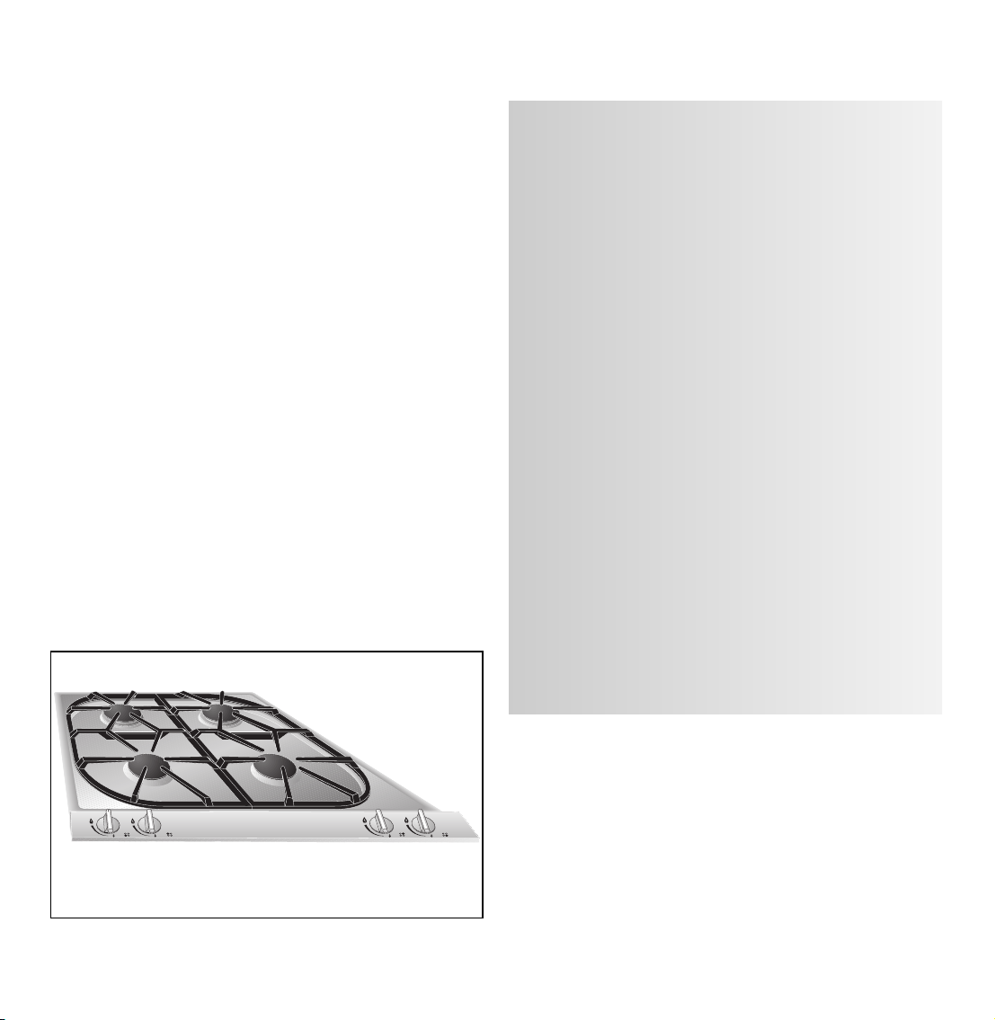
Cooking with your new gas cooker will be
even more fun than before.
The appliance offers you the following
advantages:
– Regulation from hot to cold in seconds.
– High safety standard thanks to thermal
protection elements for all burners.
– Thanks to the novel installation method
implemented, installation is child's play!
To ensure that you will be able to use this appliance in all its diversity, read through the operating
and assembly instructions conscientiously before
operating it for the first time. The instructions
contain important notes on use, installation and
maintenance of the appliance.
You will find notes on page 5 that you ought to
observe before operating the appliance for the
first time.
The chapters entitled “Structure and operating
principle" and “Operation" tell you all the
things your cooker is capable of doing and how
to operate the appliance.
The chapter entitled “Cleaning and care" will
make sure that your appliance will stay operable
and beautiful for a long time.
And now we wish you lots of fun cooking.
Preface
Fig. 1
Page 6

1.1 For your safety
You must not operate the appliance if it is damaged.
When connecting electrical appliances in the proximity of the appliance, make sure that connecting
leads do not come into contact with hot cooking
surfaces!
As the user, you yourself are responsible for
maintenance and proper use in the household.
Only ever operate the appliance under supervision.
Do not operate the appliance without pots and pans
placed on it. Make sure that all the burner parts are
correctly fitted.
Important: The appliance heats up during operation. Keep children away.
Note:
If you have fitted the appliance cover VD 201-010
(special accessory) on the appliance, it must not be
closed until the appliance has cooled down
completely. Do not operate the appliance with the
cover closed! Heat development may damage the
appliance and the cover. Do not use the appliance
cover as a surface for placing objects or for
keeping things warm.
Do not clean the appliance with a steam cleaning
apparatus or with water pressure - risk of short-
circuits!
Isolate the appliance from the mains during every
maintenance operation. To do this, remove the
mains plug or actuate the corresponding fuse.
Close the gas supply.
Repairs must be carried out by authorised specialists, thus ensuring electrical safety.
No warranty claims can be lodged for any damage
resulting from failure to observe these instructions.
Observe caution with oils and fats. They may
overheat and burn easily.
Foodstuffs that are prepared in fat and oil must only
be prepared under constant supervision!
Technical modifications reserved.
1.2 Operating for the first time
Before operating the appliance for the first time,
please pay attention to the following notes:
The appliance must only be connected by an
authorised specialist.
Read through these instructions attentively before
operating the appliance for the first time.
Note:
The rating plate for this appliance is included on
a separate sheet. Keep the rating plate in a safe
place along with your operating and assembly
instructions.
Remove the packaging from the appliance and
dispose of it properly.
Keep packaging elements away from children.
Thoroughly clean the appliance and accessories
before using them for the first time. This will
eliminate any “newness" smells and soiling
(see chapter entitled “Cleaning and care").
5
1. Important notes
Page 7

1.3 About use
The appliance is intended solely for use in the
household and must not be put to any other uses.
Use the appliance to prepare meals only. It must not
be used to heat up the room in which it is installed.
Use of a gas cooker generates heat and humidity
in the room where it is installed. This is why attention must be paid to good kitchen ventilation.
The natural ventilation openings must be kept
unobstructed. Prolonged use of the appliance
with several or all rings may call for additional
ventilation such as opening a window or a door,
or stronger air extraction by an extractor hood.
To guarantee good combustion, the room in
which the appliance is installed must have
a minimum volume of 20 m
3
and must possess
a door that opens outdoors or a window that
can be opened.
Only ever use the burners after placing pots and
pans on them. Do not heat up any empty pots
or pans; this may result in a build-up of heat. Use
pots and pans with thicker bottoms because heat
distribution is particularly improved in the low
setting. The better the size of pots and pans is
adapted to the burner size, the better the heat of
the gas flame will be exploited and the more costs
will be saved.
Cooking vessels with curved bottoms, e.g. woks,
must not be used.
It is not permitted to use roasting pans, frying pans
or grill stones heated simultaneously by several
burners because the resulting heat build-up may
damage the appliance.
Switch the burners to the low setting whenever you
remove pots or pans briefly. In this way, you reduce
the risk of burns when working next to naked
flames; you also save gas and reduce pollution.
Whenever the gas hob is fitted under a vapour
extractor hood, always cover the rings with pots
or pans. Otherwise, parts of the vapour extractor
hood may become damaged by the extreme heat
development or grease residues in the filter may
ignite. Ensure an adequate supply of air when
using a vapour extractor operating in the
exhaust air mode.
After igniting, keep the control knob pressed for
around 5-8 seconds more because the heat sensor
that opens the gas channel has to warm up first.
In the event of a power failure, you can also ignite
the unit with matches or any other ignition aid. The
thermal protection facility that prevent gas from
flowing out in the open position functions without
restriction.
Pots with a diameter of less than 90 mm (3
17
/32”) or
more than 220 mm (8
5
/8”) should not be used.
When using larger pots, pay attention to keeping to
a minimum distance of 50 mm (2”) between the
cooking vessel and combustible surroundings. A
minimum distance of 15 mm (
19
/32”) must be
observed between the control knob and the pot or
pan.
In the event of malfunctions, contact your
specialist dealer or your responsible Gaggenau
after-sales service.
Tip: When buying pots, pay attention to the fact
that the manufacturer frequently specifies the top
pot diameter, which is generally larger than the
diameter of the base.
Observe the manufacturer's specification! Use
cooking utensils that the manufacturer states as
being “suitable for gas".
Preferably use the larger cooking zone for brief
cooking, deep fat frying and brief frying of large
quantities. Preferably use the smaller ring for
soaking, warming up and keeping warm, even
when large quantities are involved.
6
Page 8

2.1 Structure
2.2 Special accessories
1 Pot grille
2 High burner, 9500 BTU (2.8 kW)
3 Normal burner, 6500 BTU (1.9 kW)
4 Control knob for the front left cooking position
5 Control knob for the rear left cooking position
6 Control knob for the rear right cooking position
7 Control knob for the front right cooking position
8 Burner head cover
9 Burner head
10 Spark plug for automatic ignition
11 Thermal sensor to safeguard the flame
You can order the following special accessories
:
– VV 200-000: Connecting strip
– VD 201-010: Appliance cover (If an appliance
cover is fitted, the pot support must
be removed when closing.)
7
2. Structure and operating principle
Fig. 3
8
9
10
11
2
2
3
3
4 5
1
6 7
Fig. 2
Page 9

2.3 Operating principle
The appliance features one-hand operation. That
is to say, the ignition is activated when the control
knob is pressed briefly.
After igniting, keep the control knob pressed for
around 5-8 seconds more because the heat sensor
that opens the gas channel has to warm up first.
The gas hob has 2 normal burners and 2 high-
intensity burners.
All burners have a thermal protection device that
prevents unburned gas from escaping in the open
position.
The total rated thermal load amounts to:
32 000 BTU (9.4 kW) referred to Hs* (gross calorific
value)
28 600 BTU (8.4 kW) referred to Hi(calorific value)
The specified rated load is defined by installation
of the fixed nozzles.
The gas hob is converted to a different gas
type by nozzle replacement (full and low-burning
nozzles) (see nozzle table on page 12).
The symbols on the control panel mean:
0 Off
High setting
Low setting
The flame is infinitely variable between high and
low-setting.
Maintenance Instructions
– Keep appliance area clean and free from
combustible materials, gasoline and other
inflammable vapors and liquids.
– Do not obstruct the flow of combustion and
ventilation air.
– Visually check burner flames with this pictorial
representation (see figure 4).
8
Fig. 4
High
Off
Low
Page 10

9
The cooking positions must only be ignited
when all burner parts are fitted. Otherwise,
malfunctions may occur on the ignition unit.
Switching on (Fig. 5):
– Place a pot or a pan on the corresponding
cooking position.
– Fully press in the control knob for the
corresponding cooking position. This activates
the ignition. Keep the control knob pressed!
–Turn the control knob to the left to the “high"
position.
If the flame should not ignite within 2 to 4 seconds,
turn the control knob further to the left to the “low"
position and then back to the “high" position after
ignition. It is often faster to ignite in the low position
because the various gases have a differing ignition
response.
After igniting, keep the control knob pressed
for around 5-8 seconds more because the heat
sensor that opens the gas channel has to warm
up first.
Repeat the operation if the flame should go out
again.
The flame size can be set continuously between full
and low by slowing turning the control knob.
Switchin
g off (Fig. 6):
Fully turn the control knob to the left to the 0
position on the left.
3. Operation
Fig. 5
Fig. 6
Page 11

Wipe off spilt food immediately, thus ensuring that
it cannot burn in on the hob.
Caution! The burner gets very hot during
operation!
Never use abrasive or caustic cleaning agents.
You should only clean the control panel and the
control knobs with detergent and a a soft cloth.
To ensure perfect functioning, keep the thermal
sensor and the spark plug clean.
Keep the incoming air openings on the rear of
the panel unobstructed and clean.
Please thoroughly clean the appliance before
operating it for the first time and after every
use.
– Wait until the appliance has cooled down.
– Remove the pot grid.
– Remove the burner cover.
– Clean the hob, the burner covers and the
pot grid with commercially available cleaning
agents (not in a dishwasher!), e.g. with warm
soap solution and a dishwashing brush.
– Whenever required, clean the burner head with
a moist cloth.
– Soak burnt-in remainders in a little water and
detergent. This loosens even the most stubborn
of soiling. Do not use any abrasive agents and
abrasive sponges.
– As the result of heat development, slight dis-
coloration can appear on the stainless steel
surface. Do not attempt to scrape away such
discoloration. This damages the surface.
Distribute stainless steel care agents uniformly
and thinly on the hob (not on the control panel!).
This will ensure an even surface and will keep
your hob in a good condition for a long period of
time.
Important: Allow the burner covers to cool down
before cleaning them!
When assembling, place the burner cover (1) on
the burner head (2) so that the four tabs on the
bottom edge of the burner cover engage in the
corresponding tabs on the burner head (see Fig. 7).
Place the pot grids back in position.
4. Cleaning and care
Caution:
Never use high-pressure or steam jet units to
clean your appliance because otherwise the
electrical safety of the appliance will no longer
be guaranteed.
10
Fig. 7
1
2
Page 12

5.1 General
5.2 Remedying slight malfunctions
yourself
The appliance must be disconnected from the
power supply during all repair work.
In the event of malfunctions, check whether the
gas and electricity supply is in proper working
order, i.e. the gas valve is open and the plug has
been plugged into the socket.
If the power supply is functioning correctly, but your
appliance still does not work, please contact your
Gaggenau dealer who will provide you with the
address and telephone number of your nearest
manufacturer’s authorized service agent or contact
Gaggenau USA on (800) 828-9165. Specify the
appliance type (see rating plate).
Repairs may only be carried out by authorised
technicians, in order to guarantee the safety of the
appliance.
Unauthorised tampering with the appliance will
invalidate any warranty claims.
Only ever use original spare parts.
11
5. Maintenance
Fault Remedy
The burner does not ignite after several attempts. Check whether ...
... the burner is correctly assembled.
... the gas shut-off facility is open.
... the burner is clean and dry.
... the domestic fuse has tripped.
If necessary, inform after-sales service.
The gas flame goes off after ignition. Check whether ...
... the burner covers are fitted correctly,
... the flame has been extinguished by a strong
draught in the room.
The cooking ring burner’s electrical igniter is no Check whether there are food remainders
longer functioning. between the ignition electrode and the burner
cover. Carefully remove these.
The flame tips are yellow and not blue. Check whether the burners are dry and clean.
Page 13

12
Technical data (gas)
Burners: Normal burner
Full burning 6500 BTU (1.90 kW)
Low burning < 1400 BTU (0.41 kW)
High-intensity burner
Full burning 9500 BTU (2.8 kW)
Low burning < 1900 BTU (0.56 kW)
Gas connection:
R 1/2’’ union nut for R 1/2’’ bracket to DIN 1999,
conical-cylindrical
Technical data, gas
Technical data (electrical)
Rated consumption 0.8 W
Voltage AC 120 V
Frequency 60 Hz
Technical modifications reserved.
6. Technical data / Settings table
Countries US US
CA CA
Gas family Natural gas Propane gas
Gas type AE
Pressure 6” W.C. (1.5 kPa) 10” W.C. (2.5 kPa)
A burner, full burning 0.94 0.74
A burner, low burning 0.49 0.36
B burner, full burning 1.28 0.87
B burner, low burning 0.58 0.42
∑Power 32 000 BTU (9.4 kW) 32 000 BTU (9.4 kW)
∑ Consumption 0.9 m
3
/h 680 g/h
Page 14

7.1 Important notes
Please observe the safety notes and the
important notes (Chapter 1).
The installing technician is responsible for
perfect functioning of the appliance at its installation location.
He must explain the operating principle to the user
with reference to the operating instructions and
must show how to switch of the electricity and gas
whenever required.
Caution:
Before connecting the appliance, please check
whether the local connection conditions such as
the gas type, gas pressure and mains voltage and
the appliance settings are correct. Refer to the
adhesive label on the gas connection or the rating
plate for the necessary information. This gas hob
conforms to the categories that are specified on the
rating plate. The rating plate can be found on the
appliance and additionally on the enclosed addendum sheet. By replacing nozzles, it is possible to
set the appliance to any gas listed on the rating
plate.
If the data should not agree, the appliance must
be set to the required gas type and the available
pressure.
As this gas hob is not intended for connection to an
exhaust gas system, pay attention to the applicable
installation conditions.
Note on ventilation:
To ensure good combustion, the room in which this
appliance is installed must have a minimum volume
of 20 m
3
and a door that opens out to outdoors or a
window that can be opened.
The appliance may be installed in kitchen
combinations made of wood or similar combustible
materials without taking additional measures. The
rear wall must consist of non-combustible material.
A minimum distance of 150 mm (6”) from heatsensitive items of furnishing or contact surfaces
(cupboard side panel) must be observed.
The hob conforms to appliance class 3 and must be
installed in the worktop as shown in the installation
sketch.
The distance between the suspended cupboard
and the worktop must be at least 600 mm (24”).
Attention must be paid to the manufacturer's
specified safety clearance when a vapour extractor
is installed.
Wall trims must be heat-resistant, and the minimum
distance between the hob and the wall trim is at
least 35 mm (1
3
/8”).
After unpacking, check the appliance for any
transportation damage and report this immediately
to the transportation company.
Technical modifications reserved.
13
7. Assembly instructions
Page 15

7.2 Connecting the appliance
G :
gas connection
:
electric socket
Electrical connection (AC 110-127 V) is established
by means of a connecting cable with a grounding
contact plug connected to a grounded socket,
which must also be accessible after installation of
the gas hob.
If, after installation of the gas hob, not all poles can
be isolated from the power by removing the plug,
an isolating device with a contact gap of at least
3 mm must be permanently installed. When establishing connections, make sure that the connecting
lead cannot come into contact with hot parts of the
gas hob or other hot parts.
Warning:
this appliance is equipped with a three prong
grounding plug for your protection against shock
hazard and should be plugged directly into a properly grounded receptacle. Do not cut or remove
the grounding prong from this plug.
The mains connecting cable must at least
correspond to type SJT 3x18 AWG/UL/CSA or it
must be correspondingly heat-resistant (at least
105 °C).
The mains connecting cable must only be
purchased through and connected by an
authorised specialist.
14
Fig. 8
G
floor
8-12” (200-300 mm)
24” (610 mm)
max 8”
(210 mm)
Page 16

15
Gas Connection
Before connecting the appliance, please check
whether the local connection conditions such as
gas type and gas pressure match the appliance
settings.
Make sure the gas supply is turned off at the
manual shut-off valve before connecting the
appliance.
The gas connection must be in a location that
permits access to the manual shut-off valve and
which, if applicable, is visible after opening the
door of the cabinet.
SERVICER INFO ONLY
Connect the gas supply using the
1
/2´ ´ U.S.A. elbow
and the fiber gasket supplied with the unit. The
shorter, nontapered thread fits into the threaded nut
on the hob. The longer, tapered U.S.A. thread is for
the incoming gas supply. Vent the gas line, check
for leaks. The gas pressure regulator is supplied
with the unit and comes set for natural gas. To
convert regulator to LP (propane) gas:
Make-Essex Model SX 229 NA-602
1
/2 PSIG
1. Remove the aluminum cap from the top of the
regulator.
2. Turn the cap over. It will have LP 10 stamped
inside.
3. Replace the cap on the regulator.
Make-Maxitrol Model RV 47 CL
1
/2 PSIG
1. Remove the aluminum cap from the top of the
regulator.
2. Remove the yellow plastic shaft from the cap by
pushing it sideways until it pops out of the
groove in the cap.
3. Turn the shaft over and push back into the cut-
out in the cap.
4. Replace the cap on the regulator.
Fig. 9
63 mm
2
1
/2”
Seal
1
/2”
Page 17

16
7.3 Nozzle replacement
Changing over to a different gas type
Only authorised specialists are permitted to
change over to a different gas type.
The nozzles needed for conversion to propane gas
are included as a kit with this appliance.
Nozzles can be replaced without having to open
the housing.
Loads for all gases
For all gas types and pressures, the rated load
is achieved by installing the high and low setting
nozzles for the required gas type (see nozzle
table).
The low setting nozzle is screwed in fully at the
works, and so the lowest quantity is set.
Replacing the low-setting nozzle 1
Proceed as follows:
– Disconnect the appliance from the power
supply!
– Remove the cover from the underside of the
appliance under the gas valves.
The low-setting nozzle 1 is located in the gas
valve and is screwed in from below. (see Fig. 10)
– Unscrew the nozzle and insert the new nozzle as
specified in the low-setting nozzle table. The
nozzle must be screwed in fully. Fit the cover
cap again.
If it should be necessary to correct the low-setting
nozzle 1 as the result of deviating gas types and
pressure, the flow rate can be increased by turning
to the left.
Fig. 10
See table on Page 12
for details of nozzle settings.
Page 18

Replacing the main nozzle 2
Proceed as follows:
– The main nozzle 2 is visible after detaching the
burner cover (see Fig. 11). It is unscrewed with a
special screw key.
– Unscrew the nozzle and insert the new nozzle as
specified in the main nozzle table. The nozzle
must be screwed in fully and firmly (torque
1.5 Nm) (metallic seal).
– Please do not forget to stick the new adhesive
label included with the nozzle set over the old
adhesive label on the gas connection, thus
documenting the changeover to a different gas
type.
Checking functions
The flames are adjusted correctly if no yellow tips
are visible and if they do not go out when switching
over swiftly from the high to the low setting.
Adjusting the primary air
The primary air setting for different gases is only
defined by the diverse nozzle shapes and therefore
does not require adjustment.
17
Fig. 11
See table on Page 12
for details of nozzle settings.
Page 19

7.4 Installing the appliance
– Produce the recess for one or several Vario
appliance(s) in your worktop. Proceed as
indicated on the installation sketch and the
dimension table. The dimension table contains
details of the space requirement for the trim
between the appliances.
Important: The angle between the cut surface
and the worktop must amount to 90° (Fig. 12).
– Mark the centre of the recess exactly. Secure
the longer securing rail on the rear edge and the
shorter securing rail on the front edge of the
recess. Make sure that the lugs of the securing
rail lie on the worktop and that the centre
marking of the securing rail is precisely flush
with the centre marking on the worktop (Fig. 13).
– Lower the appliance into the worktop. Make
sure that the engaging lugs on the appliance
lie exactly on the clamping springs. Press the
appliance firmly into the worktop. The engaging
lugs on the appliance “snap" into the clamping
springs (Fig. 14).
Note: When installing the appliance in granite
or marble worktops, have the holes produced by
a specialist or stick on the securing rails with a
temperature-resistant 2-component adhesive (metal
on stone).
18 5080006257ind02 en 02.04 EB
Fig. 12
Fig. 13
Fig. 14
Secure the appliance cover on the appliance
before installation (see VD 201-010 assembly
instructions).
Note:
Several appliances can also be installed in
individual recesses, as long as a minimum
clearance of 40 mm (1
9
/16”) is kept to between the
appliances.
m
1,4
55 1/8´´
490 mm
19 5/16´´
580 mm
22 13/16´´
48 mm/1 7/8´´
mm
8,5
/16´´
5
mm
55
/16´´
3
2
min.
mm
35
/8´´
3
1
min.
mm
50
´´
2
510 mm
20 1/16´´
in. 30
m
1
mm
/16´´
3
560 mm
22 1/16´´
ax.
m
max. 16
*
0 mm
42
*
1/2´´
Page 20

5551 McFADDEN AVENUE
HUNTINGTON BEACH, CA 92649
USA
Y (800) 828-9165 · FAX (714) 901-0979
www.gaggenau-usa.com
GAGGENAU HAUSGERÄTE GMBH
CARL-WERY-STR. 34 · 81739 MÜNCHEN
GERMANY
Y (089) 45 90-03
FAX (089)45 90-23 47
EN
 Loading...