

Page 1

Table Ventilation
AT 400
Gaggenau Operating Instructions
Page 2

Page 3
Safety notes 4
Operating for the first time 5
Maintenance 5
Features of your new appliance 6
Accessories 7
Special accessories 7
Accessories for installation 7
Operating principle 8
Operation 9
Ventilation 9
Intensive mode 9
Light 9
Special functions 10
Setting the intensive mode duration 10
Delayed shut-off 10
Interval ventilation 10
Cleaning and care 11
Cleaning the housing 11
Cleaning the grease filters 12
Replacing the activated carbon filter 13
Replacing the grease fine filter 13
Lamp replacement 14
Contents
3
Page 4

Do not operate a damaged appliance.
Carefully read through the operating instructions
before operating the table ventilation.
Keep the operating instructions for further
reference.
The table ventilation is intended solely for
household use and must not be put to any other
uses. Do not extract hazardous or explosive
substances and vapours!
Caution! Surfaces of the appliance may become hot
when used in combination with cooking appliances.
Only operate the table ventilation with the grease
filters fitted. Warning, fire risk! Very greasy, soiled
filters ignite. Clean grease filters regularly!
Only operate the table ventilation with the
florescent lamp fitted.
Use pots which fit the appliance. The top of the pot
should not touch the top of the ventilator.
Only deep fry under constant supervision.
Warning, fire risk! Switch off the ventilation when
you flambée meals!
Do not pour any liquid into the housing. If liquid
accidentally enters the housing, it will come out at
the base. You can continue using the appliance.
Warning, risk of short circuit! Do not use highpressure or steam jet cleaning devices.
Intended use
•
This extractor hood complies with the stipulated
safety regulations. Improper use may result in
injury or damage.
•
The extractor hood may be used in the
household only. The manufacturer is not liable
for damage which is caused by improper use or
incorrect operation.
•
The manufacturer cannot be made responsible
for damage which can be attributed to nonobservance of the safety instructions.
몇 RISK OF INJURY
Do not allow children to play with the extractor
hood! Adults and children must never operate the
appliance unsupervised
– if they are not physically or mentally
capable of doing so,
– or if they do not have the knowledge and
experience to operate the appliance
correctly and safely.
Technical safety
•
The extractor hood left the factory in perfect
condition. Nevertheless check the appliance for
visible damage before installation. If it is
damaged, do not switch it on!
•
If the power cord of the extractor hood is
damaged, it must be replaced by the
manufacturer, his customer service or a
similarly qualified person to prevent hazardous
situations.
•
Only a qualified technician may install
(including electrical connection), service or
repair the extractor hood. Always isolate the
extractor hood by pulling out the mains plug or
switching off the fuse!
•
If the appliance is improperly installed, serviced
or repaired, the user may be placed in
considerable danger for which the
manufacturer is not liable.
•
Changes to the electrical or mechanical
installation are dangerous and must not be
undertaken! They may also cause the extractor
hood to malfunction.
Simultaneous operation of the extractor hood
with a heating appliance which is dependent on
ambient air
•
Heating appliances which are dependent on
ambient air, e.g. gas, oil, wood, or solid-fuel
heaters, instantaneous water heaters, hot water
boilers, hobs or ovens, and which draw
combustion air out of the installation room and
whose exhaust gases are conveyed to the
exterior by a flue.
Safety notes
4
m
Page 5
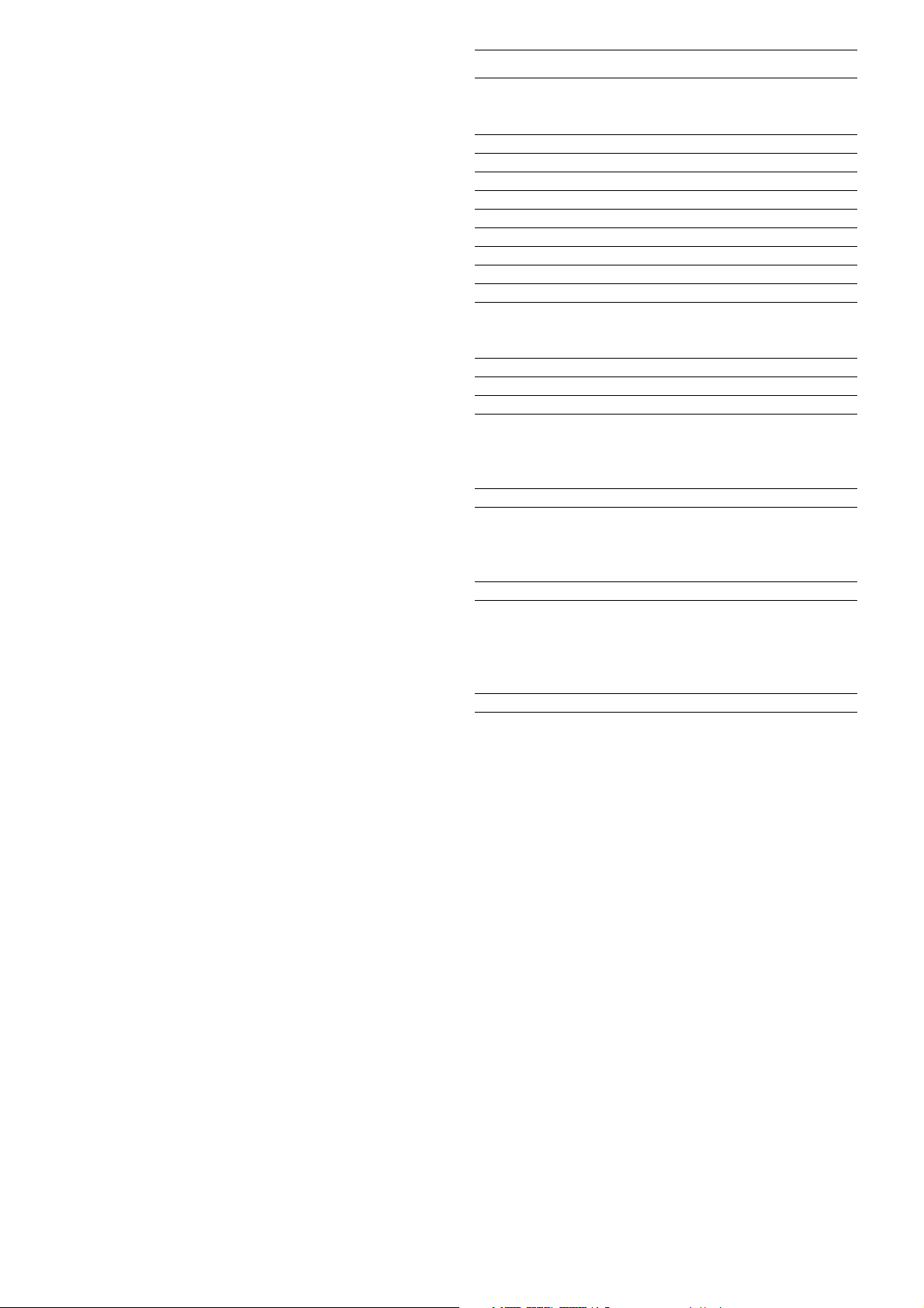
몇 RISK OF POISONING
If the extractor hood is operated at the same time as
a heating appliance which is dependent on ambient
air, there is a risk of poisoning due to combustion
gases being drawn back in.
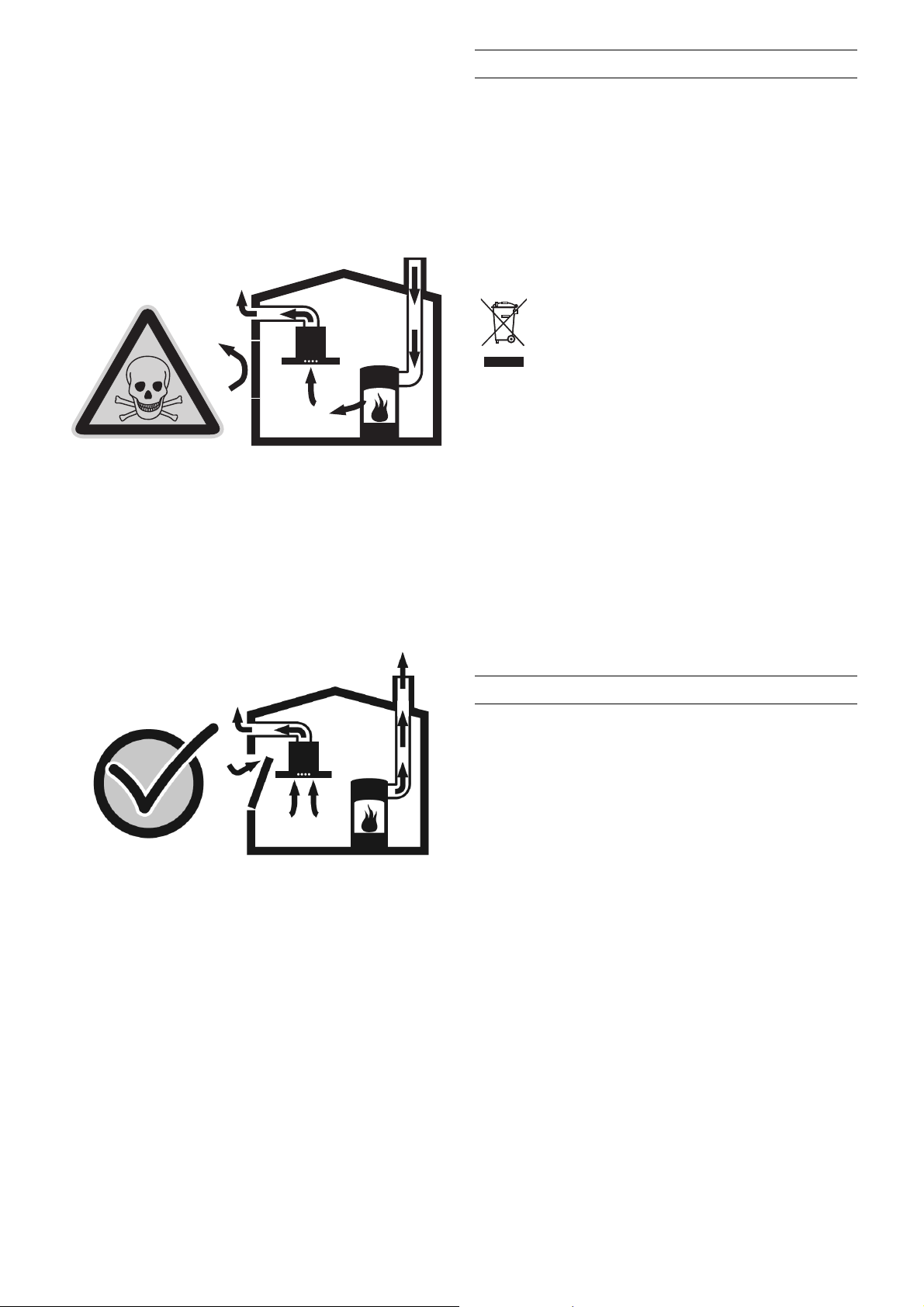
•
Safe operation is possible provided the low
pressure in the installation room of the heating
appliance does not exceed 4Pa (0.04mbar).
This can be achieved if the combustion air can
flow through non-closable openings, e.g. in
doors, windows, in conjunction with air
intake/exhaust air wall boxes or by other
technical measures.
•
Adequate intake air must therefore always be
provided.
•
An intake/exhaust air wall box alone does not
ensure compliance with the limit value.
Note: When making your evaluation, always
consider the entire ventilation system in the home.
Include the advice of a competent heating engineer
when making your evaluation.
•
If the extractor hood is used in circulating air
mode only, it can be operated without any
restrictions.
Remove the packaging from the appliance and
dispose of it according to local regulations.
Be careful to remove all accessories from the
packaging. Keep packaging elements and plastic
bags away from children.
The appliance must be installed and connected by
an authorised specialist before operation. Observe
the installation instructions!
This appliance is labelled in accordance
with the European Directive 2002/96/EG
concerning used electrical and electronic
appliances (waste electrical and electronic
equipment – WEEE). The guideline
determines the framework for the return and
recycling of used appliances as applicable.
Thoroughly clean the appliance and accessories
before using them for the first time. This will
eliminate any ‘newness’ smells and soiling.
When installing together with Vario appliances, the
appliance cover (VD 400) needs to be removed.
The frying basket holder cannot be used when
operating the deep fryer VF 411 in front of the table
ventilation.
If the appliance does not function correctly, check
the household fuses first. If the power supply is
functioning correctly, but your appliance still does
not work, please contact your dealer or your local
Gaggenau customer service agency.
Repairs may only be carried out by authorised
technicians, in order to guarantee the safety of the
appliance.
Non compliance with these recommendations
results in the warranty coverage becoming invalid.
The appliance must always be disconnected from
the mains when being repaired. If all poles of the
appliances cannot be isolated from the mains by
removing an accessible plug, an isolating device
with a contact gap of at least 3 mm must be
installed (e.g. domestic fuse).
Operating for the first time
5
Maintenance
Page 6

Combination of AT 400-101 with
Gaggenau hob CE 490 /CI 490
Features of your new appliance
6
Combination of AT 400-131 with three
Gaggenau Vario 400 series appliances
Control panel
cover light air inlet control panel
grease filter saturation display
light
delay shut off
intensive mode
ventilation level 3
ventilation level 2
ventilation level 1
ventilation off
Page 7

Special accessories
Please order the following special accessories for
air recirculation mode:
•
AA 409-100: Activated carbon filter and
grease fine filter for AT 400-100
•
AA 409-130: Activated carbon filter and
grease fine filter for AT 400-130
You can order the following special accessories for
air exhaust mode:
•
476 358: Grease fine filter for AT 400-100
•
476 363: Grease fine filter for AT 400-130
You can order the following special accessories:
•
AA 400-200: Glass cover, frosted, 106 cm,
thickness 6 mm with spacers
•
AA 400-230: Glass cover, frosted, 136 cm,
thickness 6 mm with spacers
•
AA 400-010: Wooden cutting board, beech,
53 cm
Accessories for installation
You can order the following accessories for
installation:
•
AA 409-400: Furniture support 86 cm for
AT 400-101
•
AA 409-430: Furniture support 116 cm
for AT 400-131
Recommended as bearer for the worktop,
instead of a cabinet frame, or to support the fan
housing, replacing the need for a cabinet base.
•
AA 409-900: Telescopic extension for
AT 400-101
•
AA 409-930: Telescopic extension for
AT 400-131
Telescopic extension max. 110 mm between
table ventilation and fan housing.
•
AA 010-410: Air exhaust grille for
AT 400-101/131. Stainless steel colour,
90cm as IK 300. Including installation
fittings. Height adjustable.
•
ZB 020-090: Additional louvre for air exhaust
grille AA 010-410. Height 30 mm, several
louvres can be installed.
•
AD 7.. : Cylindrical pipe ducts for air extraction
•
AD 8.. : Flat rectangular ducts for air extraction
Accessories
7
Page 8

The table ventilation is an effective air recirculation
system, which extracts the vapours directly behind
the cooktop towards the rear. The centrifugal
grease filters separate the greasy components from
the extracted air. The grease is collected in the
trays. The grease fine filter absorbs any remaining
grease particles. The activated carbon filter in the
fan housing traps odours, the exhaust outlet for the
clean air is in the furniture plinth.
For air recirculation mode in combination with VR or
VP: observe the tips to avoid smoke when frying or
grilling.
For air exhaust mode an exhaust air duct is fitted
onto the blower outlet instead of fitting the activated
carbon filter.
Operating principle
8
air intake
centrifugal grease filters
grease fine filter (fleece filter)
grease collecting trays
fan housing
activated carbon filter
(only for air recirculation mode)
exhaust outlet
Page 9

When pressed, all functions selection keys are
backlit in green, except 0 (“Motor off”).
Ventilation
Three fan speeds and one intensive speed are
available. You set the fan speed required for each
respective cooking process by pressing the
function selector keys 1, 2, 3 or Int.
Intensive mode
The Int key for the intensive level should be pressed
when browning and frying in an open pan. If you
have switched on the ventilator by selecting the
intensive level, it will be switched off again
automatically after 5 minutes.
If you press the Int key while the ventilator is
running at fan level 1, 2 or 3, the electronic control
will switch back automatically to the previously
selected fan level after 5 minutes.
If you would like to end the intensive level before
the 5 minutes have elapsed, press the 0 key
(“Motor off”) or select a different level. It is
possible to switch off the fan at any time by
pressing the 0 key (“Motor off”).
Light
The lighting can be switched on or off, regardless
of whether the ventilator extractor is in operation,
by pressing the key.
Operation
9
Page 10

Setting the intensive mode duration
You can select an intensive level running time of 3,
5 or 10 minutes by simultaneously pressing the Int
key and the 1, 2 or 3 key. When delivered, the
appliance is set to five minutes, i.e. the combination
of the Int key and the key 2.
Delayed shut-off
Delayed shut-off is possible at any level. First press
the required key 1, 2, 3 or Int and then press the
key.
The delayed shut-off time for all levels is ten
minutes. After these ten minutes, the fan switches
off, but the lighting stays on.
Interval ventilation
Interval ventilation is a special feature of this
appliance which periodically activates the fan for
five minutes every hour. You can activate this
function by simultaneously pressing the 0 key and,
depending on the required extraction capacity, the
1, 2 or 3 key.
This mode of operation is indicated by alternating
illumination of the key together with the
corresponding fan level indicator.
You can switch off interval ventilation by pressing
the 0 key.
Special functions
10
Page 11

Cleaning and care
11
Cleaning the housing
Clean the stainless steel surface of the ventilator
housing with mild detergent solution or a nonscouring stainless steel cleaner. Only wipe in the
the direction of the brushed surface. To finish,
apply some stainless steel care agent with a soft
cloth.
Do not use aggressive, abrasive or caustic cleaning
agents. Do not use cleaning agents that contain
sand or chloride. Do not use scouring pads or
brushes.
Use glass cleaner and a soft cloth to clean the lamp
glass cover. Do not put stainless steel cleaner onto
the lamp glass cover.
lamp glass cover
ventilation panel
centrifugal grease filters
grease fine filter (fleece filter)
grease collecting trays
ventilator lid
activated carbon filter
(only for air recirculation mode)
Page 12

12
Cleaning the grease filters
The grease filter saturation display F flashes after
an operating time of 10 hours to indicate that you
should clean the grease filters.
Depending on the cooking habits it may be
necessary to clean the grease filters at shorter
intervals (for example if kitchen smells appear when
the ventilation is switched off).
The centrifugal grease filters can be easily removed
for cleaning:
1 Disconnect the appliance from the mains
(switch off fuse).
2 Tilt the ventilation panel to the rear. For easier
cleaning you can remove the panel: On both
sides of the panel at the top, lift over the studs
and remove to the front.
3 Remove the centrifugal grease filters one by
one (from right to left).
4 Remove the grease collecting trays (from right
to left) and empty.
You can clean the centrifugal grease filters and the
grease collecting trays in a dishwasher. Place the
filters upright ín the dishwasher, with the opening
face down.
Wipe out the inner parts of the housing with a moist
cloth and some detergent when removing the filters.
Caution: Beware of protruding parts when cleaning
the inside of the housing.
Do not pour any liquid into the housing. If liquid
accidentally enters the housing, it will reappear at
the base.
Refit the grease filters in the correct order (from left
to right). Refit the parts so that the markings
correspond with the markings on the housing.
Press the F key to reset the counter. Flashing of the
indicating lamp goes off.
Page 13

13
Replacing the activated carbon filter
(only for air recirculation mode)
The activated carbon filter in the fan housing (lower
part of the appliance) eliminates smells from the
extracted air. For hygenic reasons, change the
activated carbon filter together with the grease fine
filter at least every six months or when kitchen
smells appear. The activated carbon filter with the
grease fine filter is available from your specialist
dealer. Only use original filters.
Note: If no activated carbon filter is fitted or if it
is saturated, no odours can be removed from the
circulating air.
1 Disconnect the appliance from the mains
(switch off fuse).
2 Open the latches on the bottom of the fan
housing. Take off the ventilator lid by pulling the
bottom edge.
3 Remove activated carbon filter. Insert new
activated carbon filter. The filter mat must lie
flat.
4 Refit the ventilator lid.
Activated carbon filters do not contain any
polluting substances. They can be disposed of
through the household refuse collection.
Replacing the grease fine filter
The grease fine filter (fleece filter) is fitted behind
the centrifugal grease filters.
1 Disconnect the appliance from the mains
(switch off fuse).
2 Tilt the ventilation panel to the rear.
3 Remove the centrifugal grease filters one by
one (from right to left).
4 Pull out the grease fine filter from the mounting.
5 Push the new grease fine filter under the
braces. Refit the centrifugal grease filters in the
reverse order (from left to right).
Grease fine filters do not contain any polluting
substances. They can be disposed of through the
household refuse collection.
Page 14

Wait until the appliance has cooled down before
replacing lamp.
1 Disconnect the appliance from the mains
(switch off fuse).
2 Remove loose objects from the cover.
3 Lift off cover.
4 First turn florescent lamp in the socket, then lift
off fluorescent lamp.
5 Only replace defective fluorescent lamp by
lamp of the same type.
6 Insert the new fluorescent lamp into the socket.
Turn the fluorescent lamp in the socket until it
engages.
7 Evenly replace cover onto the appliance.
8 Connect the unit to the power mains again.
Lamp replacement
14
Page 15

Page 16

Gaggenau Hausgeräte GmbH
Carl-Wery-Straße 34
D-81739 München
www.gaggenau.com
9000137543 EB 8910 en
 Loading...