

Page 1
B
B
X--
X
1
1
0
0
0
0
0//
0
B
B
X
X
G--
G
1
1
0
0
0
0
0
0
Grr
G
Wii
W
OPERATION MANUAL
o
o
o
o
dtt
d
v
e
v
e
h
h
Dii
D
G
G
a
a
a
a
g
g
m
m
e
s
e
s
ett
e
err
e
a
a
n
n
d
d
Page 2

BBXX//BBXXGG--11000000 SSeerriieess GGrroooovvee MMeeaassuurreemmeenntt GGaaggee OOppeerraattiioonn MMaannuuaal
2
©2012 Gagemaker, LP
Rev Nov. 28, 2012
OMBX100011-01
l
Page 3

BBXX//BBXXGG--11000000 SSeerriieess GGrroooovvee MMeeaassuurreemmeenntt GGaaggee OOppeerraattiioonn MMaannuuaal
3
l
Contents
Introduction
Technical Support 7
Product Information and Updates 7
System Components
BX-1000 Gage Component List 8
BXG-1000 Gage Component List 9
BX-1000 Setup Procedures
Setting Up the BX-1000 Gage 10
Zeroing the BX-1000 Gage Using the MIC TRAC 14
Changing from Internal to External Measurement direction 18
BX-1000 Operating Procedu res
Inspecting Parts with the BX-1000 Gage 19
BXG-1000 Setup Procedures
Setting Up the BXG-1000 Gage 21
Zeroing the BXG-1000 Gage Using Gage Blocks 23
Zeroing the BXG-1000 Gage Using the MIC TRAC 25
BXG-1000 Operating Procedures
Inspecting Parts with the BXG-1000 Gage 29
Groove Inspection Tolerances
6R & 6RX Groove Tolerances 31
6BX Groove Tolerances 31
Setting Dimensions
MIC Over Ba ll Set t ing Dimensions 32
Origin of MIC TRAC Setting Dimensions 33
MIC TRAC Setting Dimensions 34
Care and Maintenance
Maintenance Tips 35
Warranty Information 35
Page 4

BBXX//BBXXGG--11000000 SSeerriieess GGrroooovvee MMeeaassuurreemmeenntt GGaaggee OOppeerraattiioonn MMaannuuaal
4
l
Page 5

BBXX//BBXXGG--11000000 SSeerriieess GGrroooovvee MMeeaassuurreemmeenntt GGaaggee OOppeerraattiioonn MMaannuuaal
5
Congratulations! Your decision to purchase a Gagemaker product above all others on the market
demonstrates your confidence in our quality and workmanship.
To ensure the high performance and operation of our product, we urge you to use the included reference
materials. They contain important information for proper installation, setup, and use of the equipment. In
addition, we recommend that you follow the care and maintenance tips in this manual to keep the
equipment working in top condition.
l
If your questions are not addressed in our reference materials, contact your local representative
or a customer service representative at 713-472-7360 or info@g agemaker.com.
Page 6

BBXX//BBXXGG--11000000 SSeerriieess GGrroooovvee MMeeaassuurreemmeenntt GGaaggee OOppeerraattiioonn MMaannuuaal
6
l
Page 7

BBXX//BBXXGG--11000000 SSeerriieess GGrroooovvee MMeeaassuurreemmeenntt GGaaggee OOppeerraattiioonn MMaannuuaal
7
l
Introduction
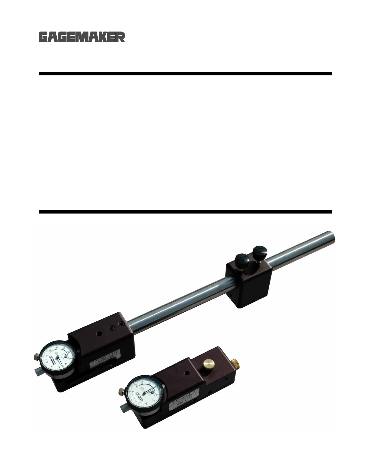
The BX-1000 and BXG-1000 gages measure face groove diameters and widths. These gages adjust to
cover all sizes of R, RX, and BX ring grooves. The standard BX-1000 gage measures groove diameters
from 2.6” – 13”. Optional rails extend the range of diameters from 13” – 36”. The BXG-1000 inspects
groove widths from .34” – 1.5”.
The BX-1000 can be used to measure straight or tapered groove diameters, shallow bores, and hole
locations. The gage ships standard with .188” diameter contact points. The BXG-1000 measures widths
of straight or tapered grooves and includes .072” diameter contact points.
The BX and BXG gages use precision contact points for accurate measurement of the ring groove
diameter and width at the critical sealing point of the face groove.
Before inspecting parts, the BX and BXG gages require presetting to a nominal predetermined
dimension. The Groove Inspection Tolerances and Setting Dimension tables in this manual determine
the gage’s setting dimensions and gauging tolerances. The BX-1000 gages can be preset using
micrometers, gage blocks, or the MIC TRAC MT-3000 measurement center.
To inspect parts, place the contact points in the groove of the part and the gage is positioned by
sweeping to obtain an indicator reading. Gage indicators show actual deviation from the preset master
dimension. Taking measurements in several different locations along the groove will provide an
average groove diameter or groove width. In addition, we recommend that the gage be zeroed
periodically during use to maintain accurate readings.
Technical Support
Phone: 713-472-7360
Hours: Monday – Friday 8AM – 5PM (CST)
Product Information and Updates
Visit our web site: www.gagemaker.com
Page 8
BBXX//BBXXGG--11000000 SSeerriieess GGrroooovvee MMeeaassuurreemmeenntt GGaaggee OOppeerraattiioonn MMaannuuaal
8
5 89
312
4
11 810
7
6
7
6
System Components
l
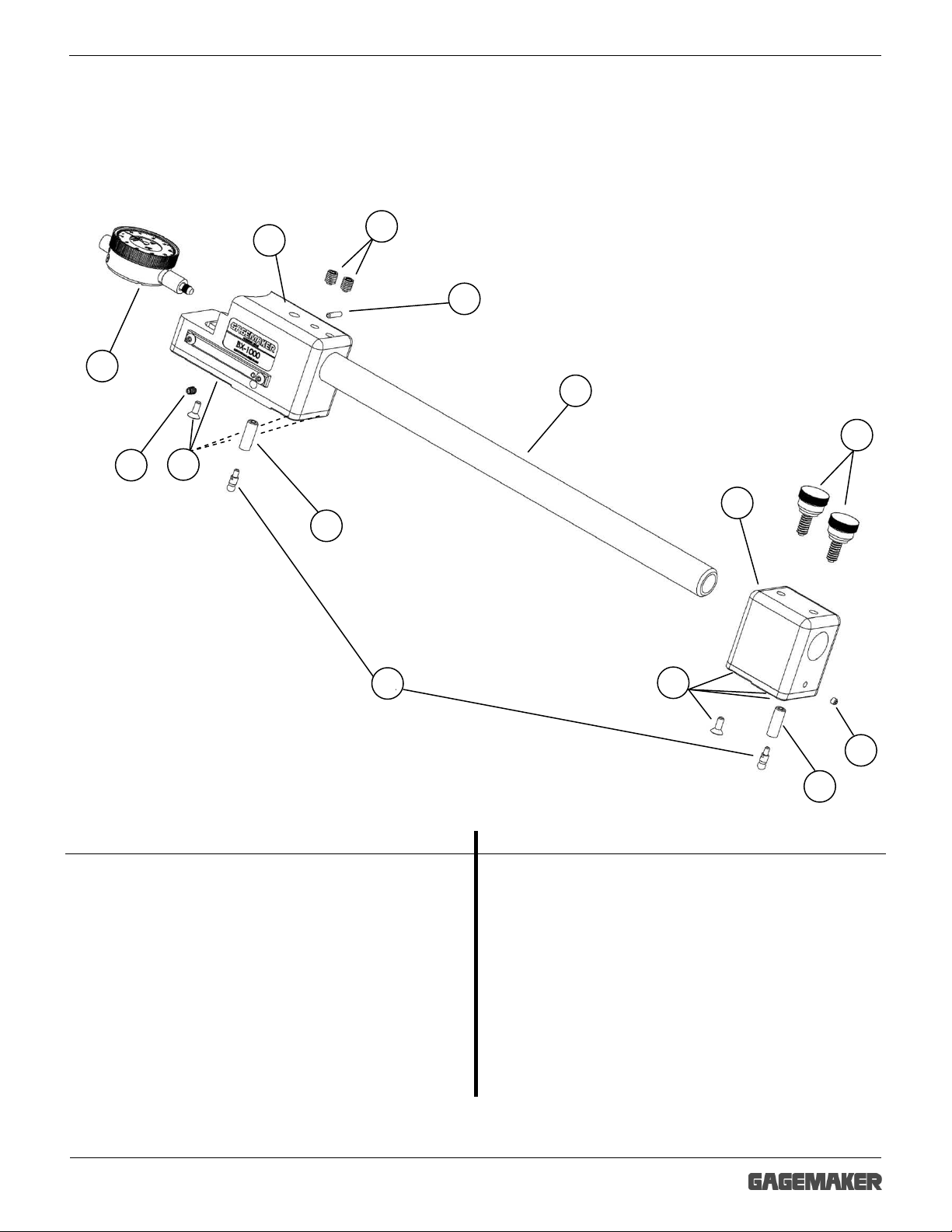
Take some time to become familiar with all the parts that make up the BX-1000 gages by
reviewing the labeled diagram below. The part names are important for understanding the
operating instructions.
BX-1000 Model Gage
2
Component List
Item Description Model Qty Item Description Model Qty
Upper block assembly
1
with wear pad
2 Extension rod lock screw
3 Indicator set screw
Lower block assembly
4
with wear pad
5 Lock knob
6-32 X ⅜” Flat head wear
6
pad screws
BX-1000-1A
BX-1000-2A
BX-1000-3A
BX-1000-4A 1 10 Contact point T188 2
BX-1000-5A
BX-1000-6A 8
1 7
2 8 Contact point lock screw BX-1000-8A 2
1 9 Indicator 803 or 513SGA 1
2 11 Extension rod BX-R13 1
Contact point adjustment
screw (¼-28 x ¾”)
BX-1000-7A 2
Page 9
BBXX//BBXXGG--11000000 SSeerriieess GGrroooovvee MMeeaassuurreemmeenntt GGaaggee OOppeerraattiioonn MMaannuuaal
9
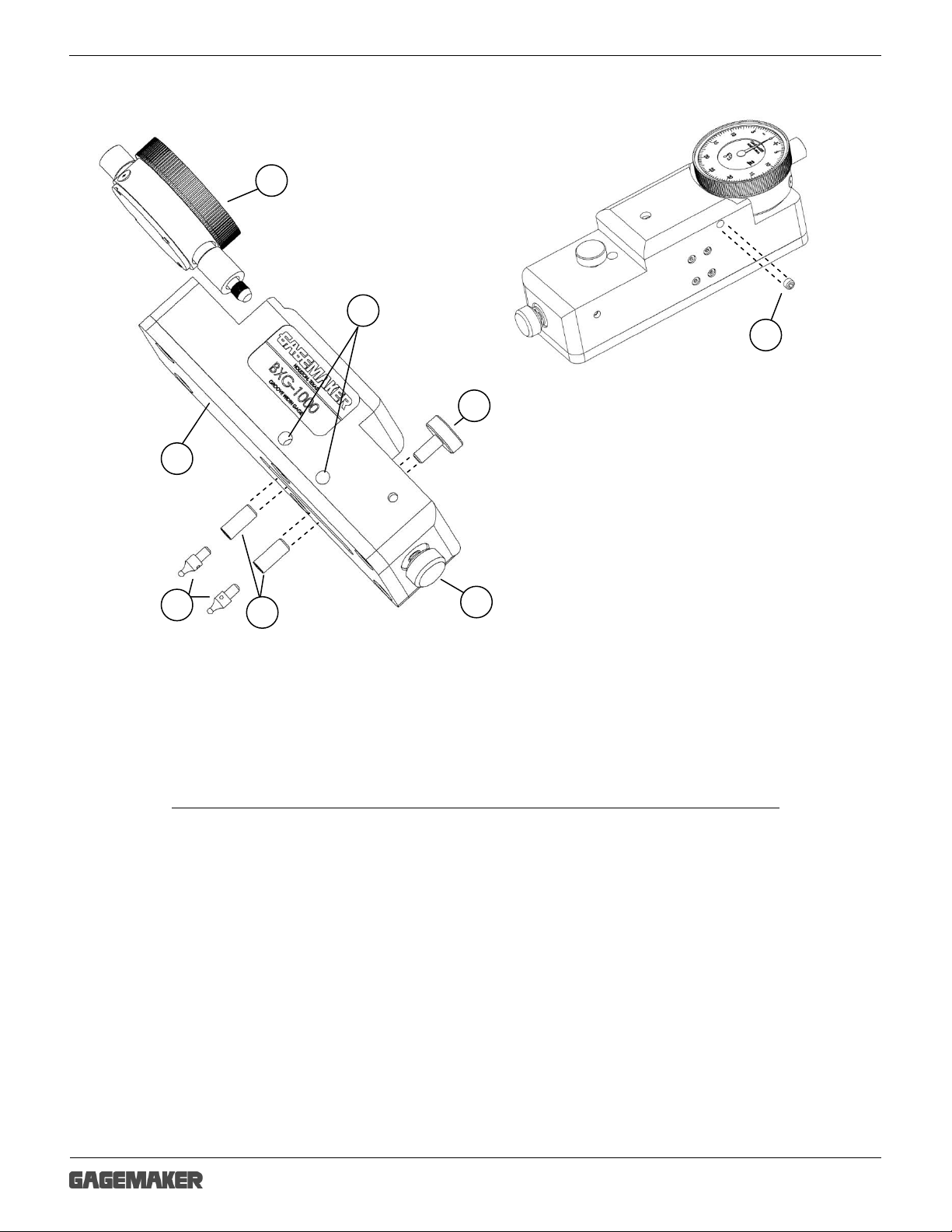
BXG-1000 Model Gage
16 3
7
2 4 5
8
Component List
Item Description Model Qty
l
1 Wear Pad BXG-1000-1A 1
2 Lock screw (8-32 x ⅛”, brass tipped) BXG-1000-2A 2
3 Rear contact point lock knob BXG-1000-3A 1
4 Contact point adjustment knob BXG-1000-4A 1
5 Contact point adjustment screw (10-32 X ½”) BXG-1000-5A 2
6 Contact point T072 2
7 Indicator 803 or 513SGA 1
8 Indicator lock screw (8-32 x ⅛”)
BX-1000-3A
1
Page 10
BBXX//BBXXGG--11000000 SSeerriieess GGrroooovvee MMeeaassuurreemmeenntt GGaaggee OOppeerraattiioonn MMaannuuaal
10
Setup Procedures
Setting Up the BX-1000 Gage
Materials Needed:
• BX-1000 gage
• Gage blocks
l
1. Inspect the contact points to ensure that they
are tight.
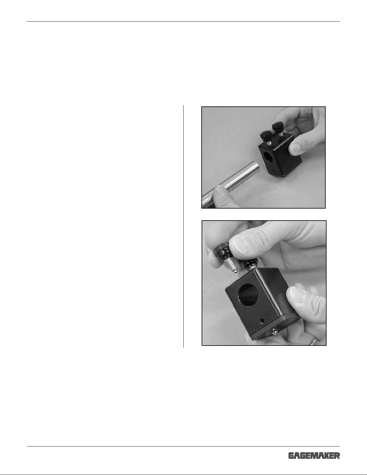
2. Loosen the lower block locking knobs and slide
the lower block off the extension rod.
3. Remove the lower block locking knob so the
contact point can be adjusted.
Page 11
BBXX//BBXXGG--11000000 SSeerriieess GGrroooovvee MMeeaassuurreemmeenntt GGaaggee OOppeerraattiioonn MMaannuuaal
11
Setting Up the BX-1000 Gage (continued)
l
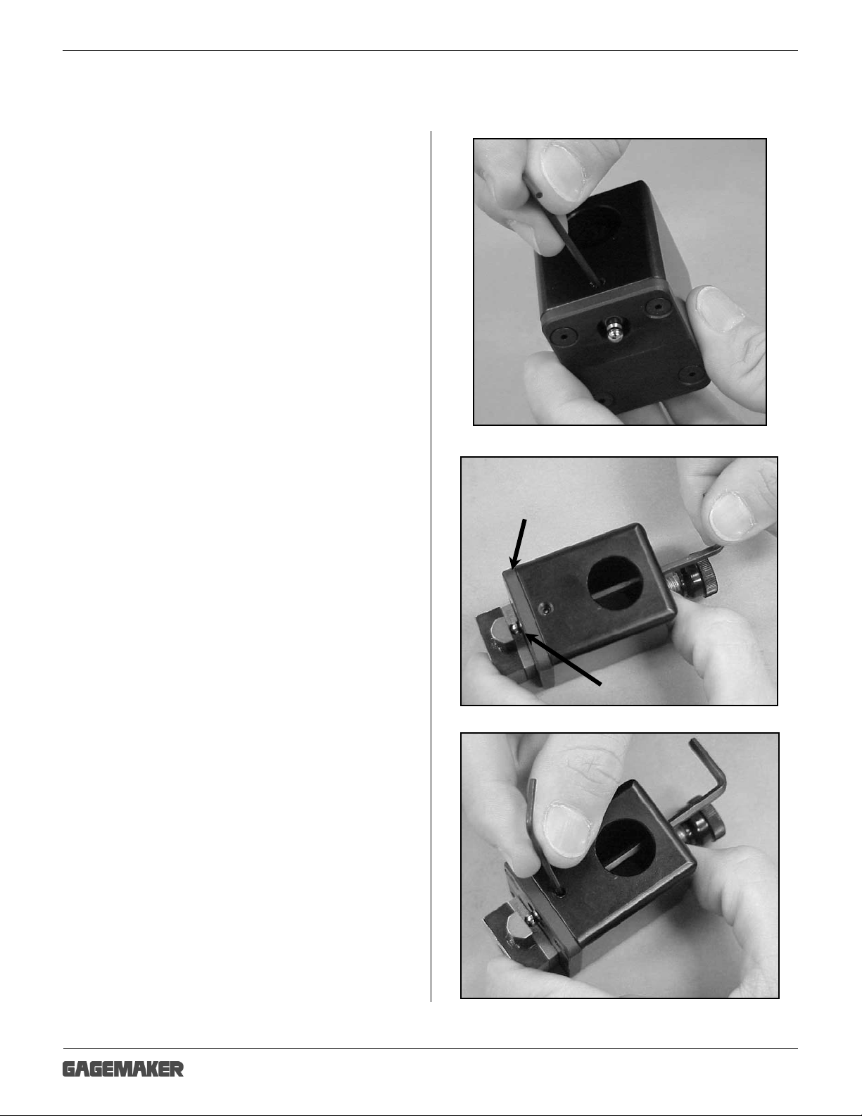
4. Using a 5/64” hex wrench, loosen the
contact point set screw in the lower
block.
5. Place a 1/8” hex wrench down the access hole
in the top of the lower block.
6. Using a .188” gage block, turn the hex wrench
to adjust the set screw so the distance from the
wear pad to the bottom of the contact point is
.188”.
Wear Pad
Contact Point
7. Using the 5/64” hex wrench, tighten the contact
point in the lower block.
Page 12
BBXX//BBXXGG--11000000 SSeerriieess GGrroooovvee MMeeaassuurreemmeenntt GGaaggee OOppeerraattiioonn MMaannuuaal
12
Wear Pad
Setting Up the BX-1000 Gage (continued)
l
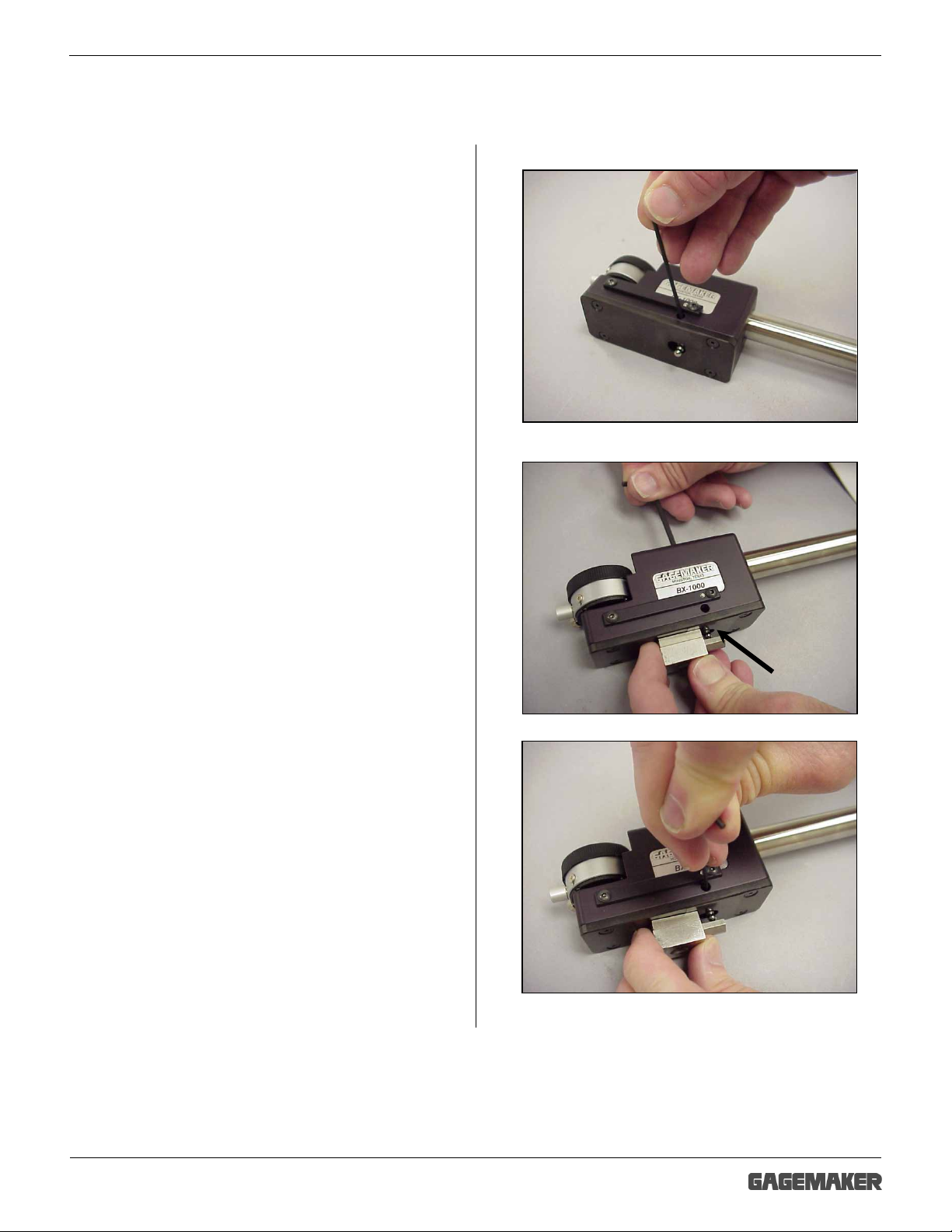
8. Using a 5/64” hex wrench, loosen the contact
point in the upper block.
9. Place a 1/8” hex wrench down the access hole
in the top of the upper block.
10. Using a .188” gage block, turn the hex wrench
to adjust the set screw so the distance from the
wear pad to the bottom of the contact point is
.188”.
Contact Point
11. Using the 5/64” hex wrench, tighten the contact
point in the upper block.
Page 13
BBXX//BBXXGG--11000000 SSeerriieess GGrroooovvee MMeeaassuurreemmeenntt GGaaggee OOppeerraattiioonn MMaannuuaal
13
Setting Up the BX-1000 Gage (continued)
l
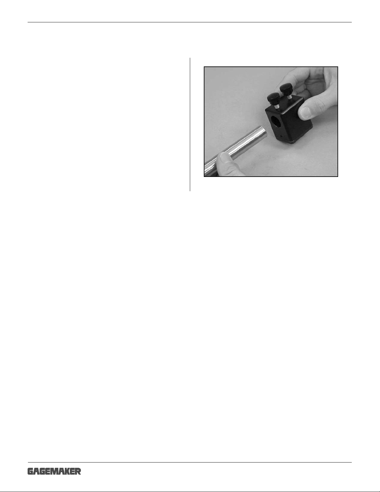
12. Replace the locking knob in the lower block.
13. Place the lower block on the extension rod and
tighten the locking knob to secure.
Page 14
BBXX//BBXXGG--11000000 SSeerriieess GGrroooovvee MMeeaassuurreemmeenntt GGaaggee OOppeerraattiioonn MMaannuuaal
14
Zeroing the BX-1000 Gage Using the MIC TRAC
Materials Needed:
• BX-1000 gage
• MIC TRAC MT-3000
To ensure consistent and accurate readings, the BX-1000 gage should be zeroed on the MIC
TRAC once during each shift, at a minimum.
• MIC TRAC Setting Dimensions Table
l
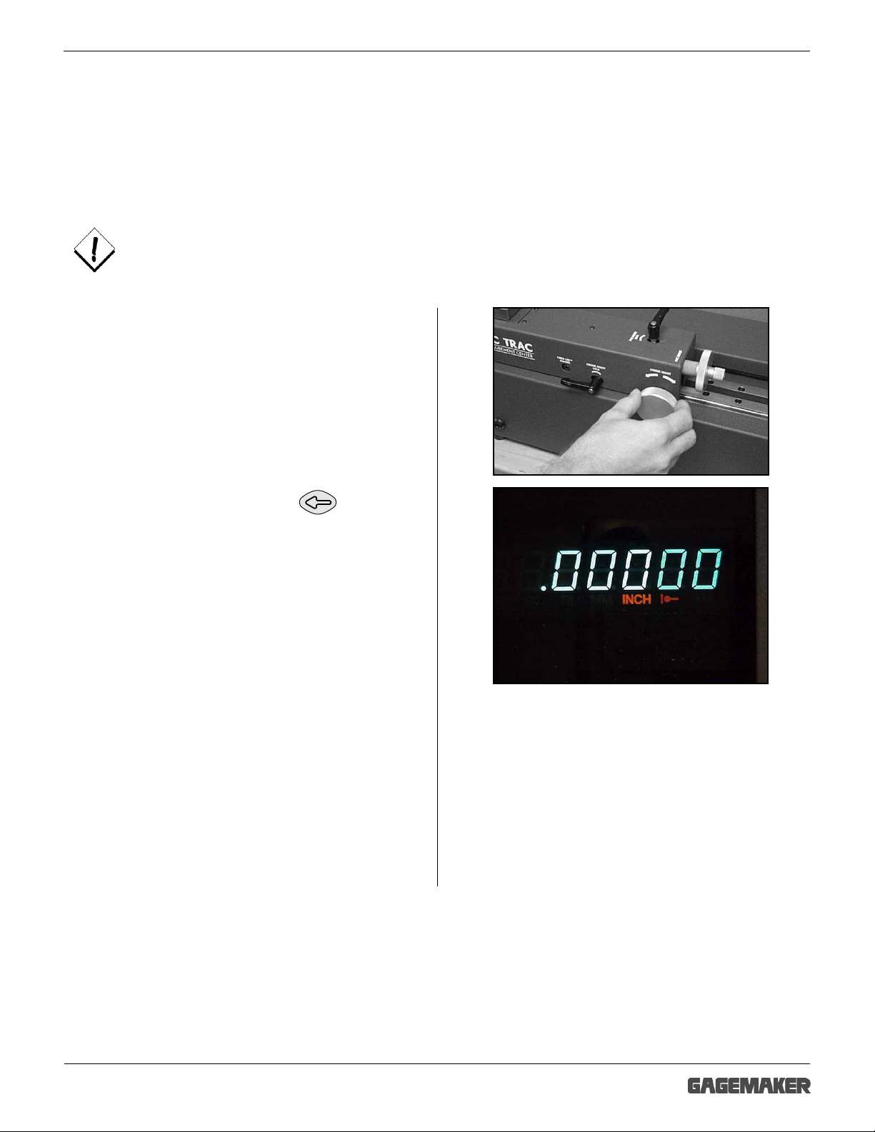
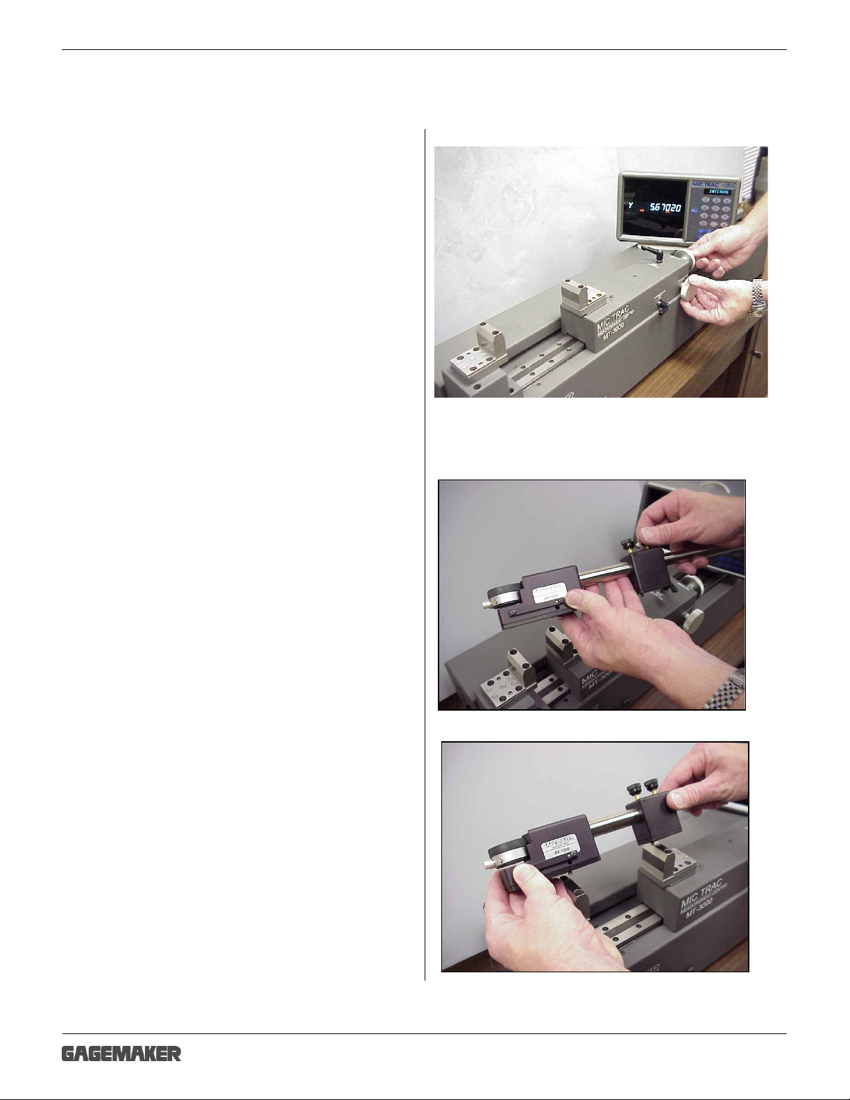
1. Mount the TF-BX setting blocks on the MIC
TRAC.
1. Turn the coarse adjust knob on the MIC TRAC
counterclockwise to bring the setting blocks
together.
2. Apply slight pressure to hold the faces of the
anvils together. Press the key and
the display will read 0.00000.
Page 15
BBXX//BBXXGG--11000000 SSeerriieess GGrroooovvee MMeeaassuurreemmeenntt GGaaggee OOppeerraattiioonn MMaannuuaal
15
3. Locate the dimension for the type of groove
Zeroing the BX-1000 Gage Using the MIC TRAC (continued)
you are measuring in the MIC TRAC Setting
Dimensions table in this manual.
4. Turn the coarse adjust knob on the MT-3000 to
display a measurement that is close to the
desired setting dimension.
5. Secure the coarse adjust lock.
6. Turn the fine adjust knob until the CPU displays
the exact setting dimension.
7. Secure the fine adjust lock.
l
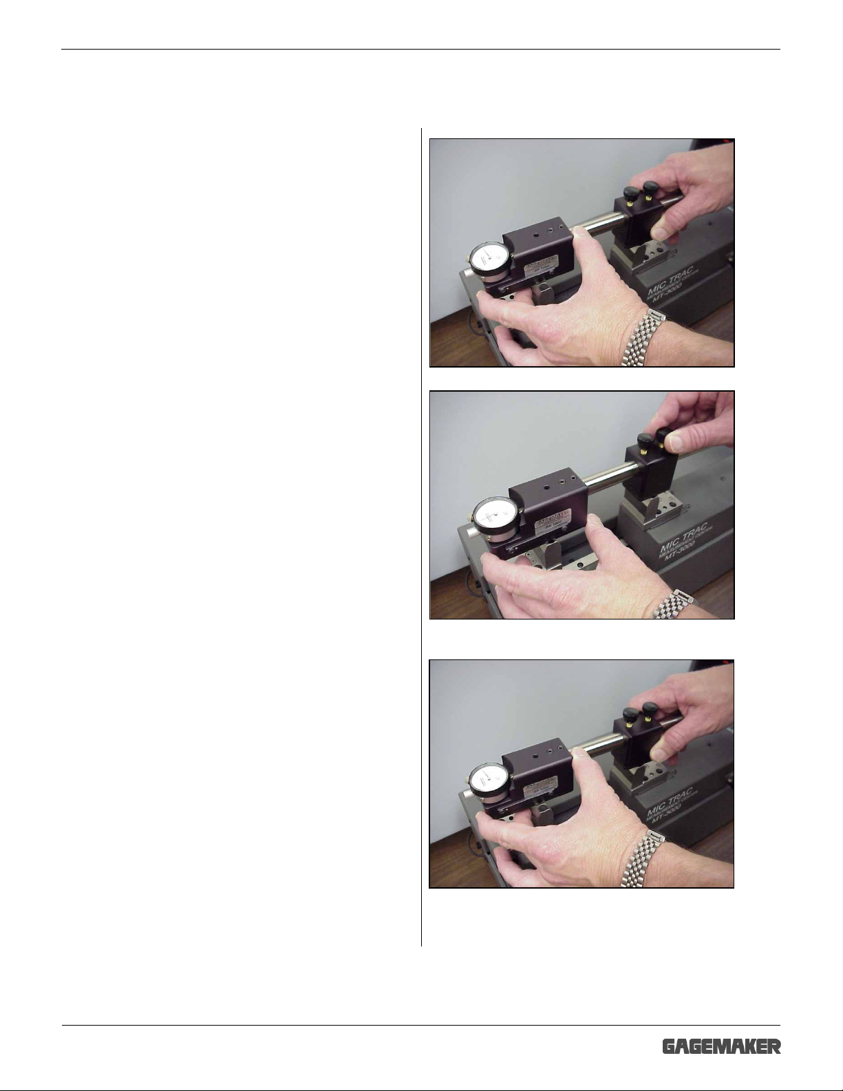
8. Loosen the lower block locking knobs and slide
the lower block to a position that allows the BX1000 gage to set on the top surfaces of the
setting blocks.
9. Place the BX-1000 gage on the setting blocks,
positioning the contact points between the
setting blocks.
Page 16
BBXX//BBXXGG--11000000 SSeerriieess GGrroooovvee MMeeaassuurreemmeenntt GGaaggee OOppeerraattiioonn MMaannuuaal
16
Zeroing the BX-1000 Gage Using the MIC TRAC (continued)
l
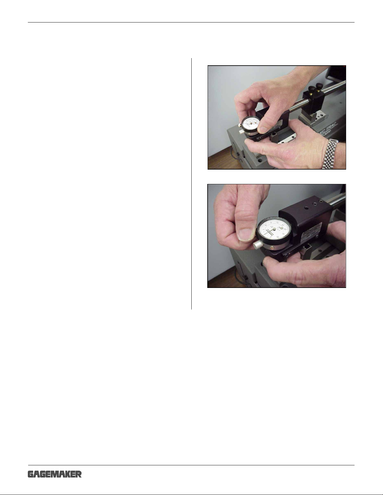
10. Rotate the lower block so that the wear pads
lay flat on the setting blocks.
11. Adjust the lower block so the contact points
touch the setting blocks and the indicator has
approximately 0.010” to 0.020” of preload.
12. Tighten the lower block locking knob to secure.
13. While maintaining pressure toward the right
setting block, sweep the upper block back and
forth to locate the smallest indicator reading.
Page 17
BBXX//BBXXGG--11000000 SSeerriieess GGrroooovvee MMeeaassuurreemmeenntt GGaaggee OOppeerraattiioonn MMaannuuaal
17
Zeroing the BX-1000 Gage Using the MIC TRAC (continued)
l
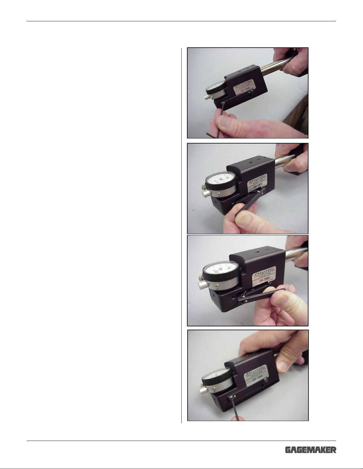
14. Turn the indicator dial on the BX-1000 gage to
align the needle with zero.
15. Tighten the indicator clamp.
Note: Note the position of the small revolution
counter on the indicator before removing
the gage. Place a piece of masking tape on
the side of the gage and record the dial
setting of the small revolution counter to
eliminate incorrect indicator readings.
16. Set a frequency for verifying the zero setting of
all gages. As a minimum, the BX-1000 gage
should be zeroed on the MIC TRAC once
during each shift to ensure accurate readings.
Page 18
BBXX//BBXXGG--11000000 SSeerriieess GGrroooovvee MMeeaassuurreemmeenntt GGaaggee OOppeerraattiioonn MMaannuuaal
18
Changing from Internal to External Measurement Direction
1. Remove the two screws holding the spring-pin
cover plate.
2. Turn the cover plate around 180 degrees.
l
3. Replace the two cover plate hold down screws.
Page 19
BBXX//BBXXGG--11000000 SSeerriieess GGrroooovvee MMeeaassuurreemmeenntt GGaaggee OOppeerraattiioonn MMaannuuaal
19
Operating Procedures
Inspecting Parts with the BX-1000 Gage
Materials Needed:
• BX-1000 gage
• Part
• Inspection report
l
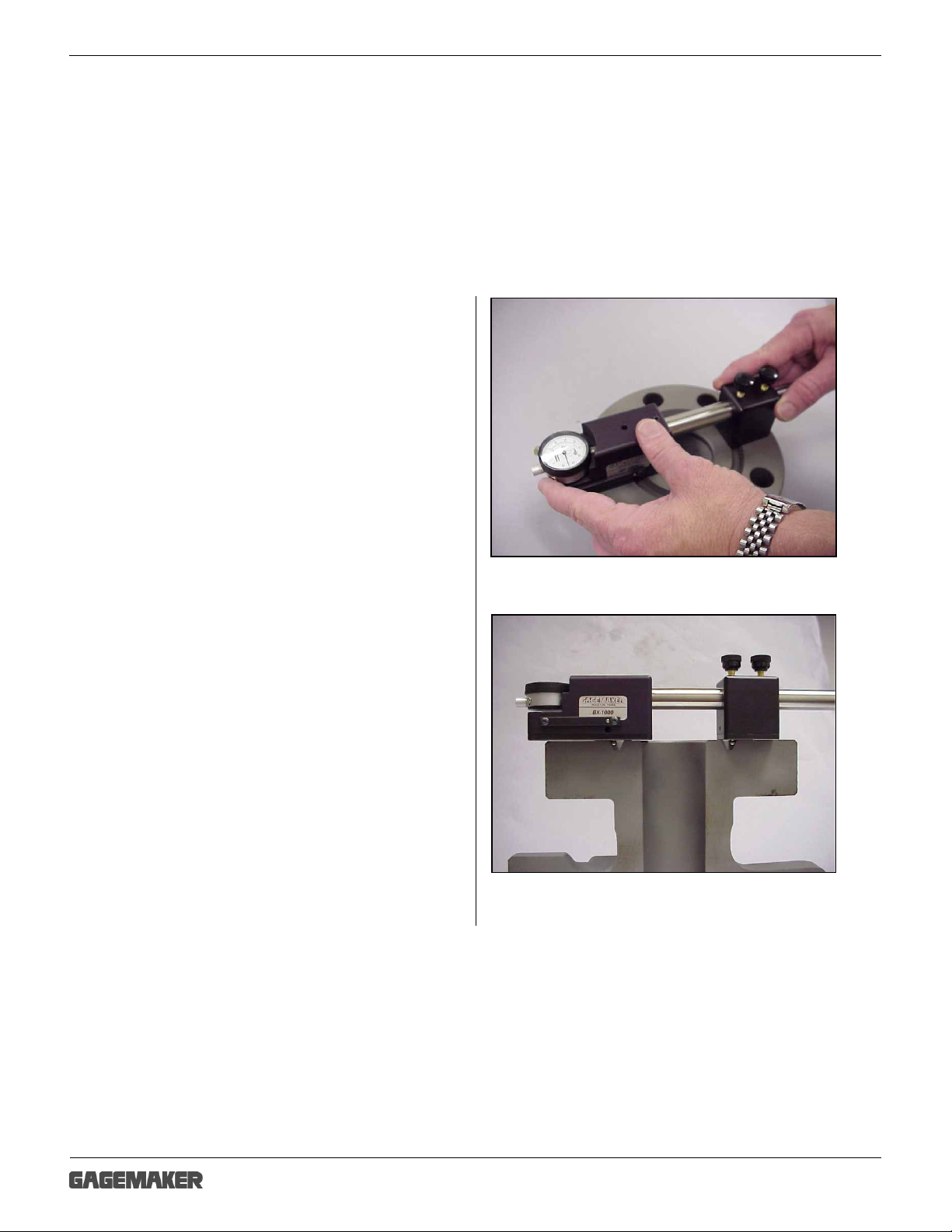
4. After zeroing the BX-1000 gage, position the
gage on the flange face and into the ring
groove of the part.
5. Properly position the contact points in the
groove, as shown to the right.
Page 20
BBXX//BBXXGG--11000000 SSeerriieess GGrroooovvee MMeeaassuurreemmeenntt GGaaggee OOppeerraattiioonn MMaannuuaal
20
Inspecting Parts with the BX-1000 Gage (continued)
l
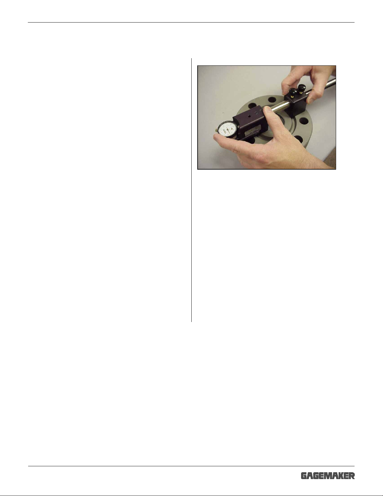
6. While maintaining pressure toward the lower
block and flange face, sweep the gage back
and forth, using the lower block as a pivot, to
locate the largest indicator reading.
Note: Be sure that the small revolution counter on
the indicator is pointing to the same number
as when the gage was zeroed. Refer to the
number previously recorded on the side of
7. Repeat the process in several locations around
8. Locate the groove diameter in the 6B & 6BX
9. Record the information on an inspection report.
10. Inspect the part with the BXG-1000 to ensure
11. Use the first part you inspected as a control
12. During the inspection process, periodically
the gage.
the groove to get an average groove diameter.
Groove Inspection Tolerances table in this
manual to determine the groove width
tolerance.
the proper groove width.
piece to verify repeatability. Mark the part at a
location where it was inspected and record the
deviation from zero.
place the BX-1000 on the control piece to verify
the gage’s accuracy.
Page 21
BBXX//BBXXGG--11000000 SSeerriieess GGrroooovvee MMeeaassuurreemmeenntt GGaaggee OOppeerraattiioonn MMaannuuaal
21
Setting Up the BXG-1000 Gage
Materials Needed:
• BXG-1000 gage
• Gage block
l
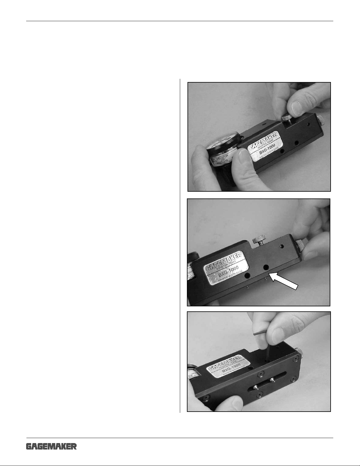
1. Inspect the contact points to ensure that they
are tight.
2. Loosen the rear contact point lock knob,
located on the top of the gage.
3. Turn the contact point adjustment knob, located
on the rear of the gage, to adjust the point
location until the rear lock screw is aligned with
the access hole in the side of the gage body.
Note: Aligning the lock screw allows you to place
a hex wrench in the access hole and loosen
the lock screw.
Rear Lock Screw
4. Using the 5/64” hex wrench, loosen the front
and rear lock screws.
Page 22
BBXX//BBXXGG--11000000 SSeerriieess GGrroooovvee MMeeaassuurreemmeenntt GGaaggee OOppeerraattiioonn MMaannuuaal
22
Setting Up the BXG-1000 Gage (continued)
l
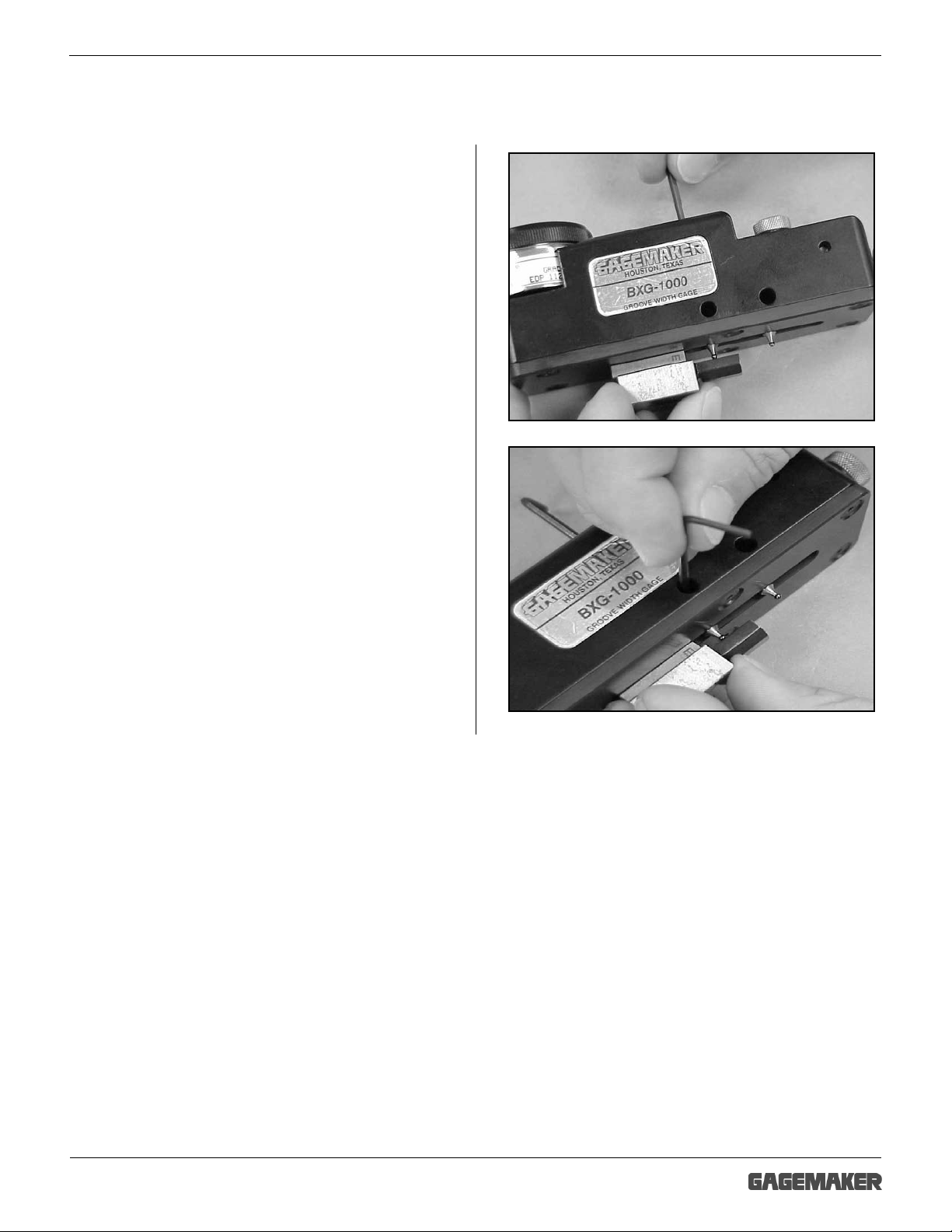
5. Using a 3/32” hex wrench and proper gage
blocks, adjust the height of the contact points
as follows:
• For setting with the MIC TRAC and TF-
BX blocks – adjustment is approximately ½
the groove depth.
• For setting with a micrometer or gage
blocks: adjustment is .157” from the face of
the gage.
6. Tighten the front and rear lock screws.
Page 23
BBXX//BBXXGG--11000000 SSeerriieess GGrroooovvee MMeeaassuurreemmeenntt GGaaggee OOppeerraattiioonn MMaannuuaal
23
Zeroing the BXG-1000 Gage Using Gage Blocks
Materials Needed:
• BXG-1000 gage
• Gage blocks
To ensure consistent and accurate readings, the BXG-1000 gage should be zeroed on gage
blocks once during each shift, at a minimum.
• MIC Over Ball Setting Dimensions Table
l
1. Locate the dimension for the type of groove
you are measuring in the MIC Over Ball
Setting Dimensions table in this manual.
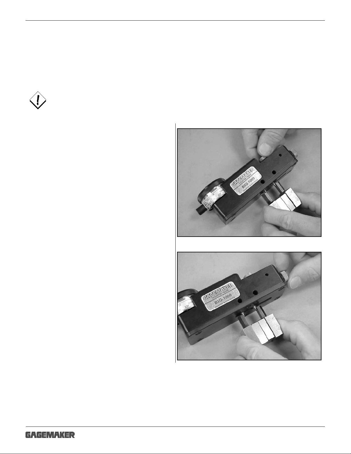
2. Stack the gage blocks to the proper
measurement.
3. Turn the rear contact point lock knob, located
on the top of the gage, to loosen the contact
point holder.
4. Turn the contact point adjustment knob,
located at the rear of the gage, to adjust the
location of the rear contact point.
5. Continue turning the adjustment knob until the
contact points fit between the gage blocks.
6. Lock the rear contact point lock knob.
Page 24
BBXX//BBXXGG--11000000 SSeerriieess GGrroooovvee MMeeaassuurreemmeenntt GGaaggee OOppeerraattiioonn MMaannuuaal
24
Zeroing the BXG-1000 Gage Using Gage Blocks (continued)
l
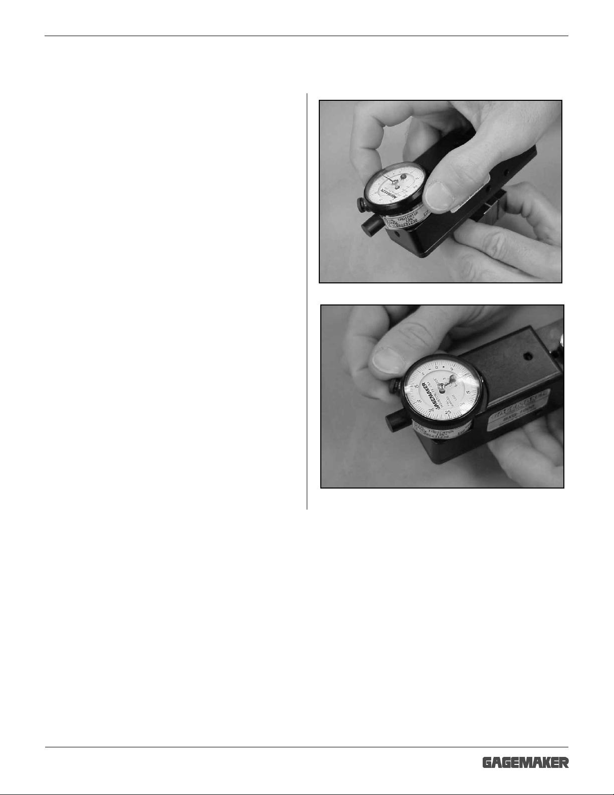
7. Turn the indicator dial on the BXG-1000 gage
to align the needle with zero.
8. Tighten the indicator clamp.
Note: Note the position of the small revolution
counter on the indicator before removing
the gage. Place a piece of masking tape on
the side of the gage and record the dial
setting of the small revolution counter to
eliminate incorrect indicator readings.
9. Set a frequency for verifying the zero setting of
all gages. As a minimum, the BXG-1000 gage
should be zeroed on gage blocks once during
each shift to ensure accurate readings.
Page 25
BBXX//BBXXGG--11000000 SSeerriieess GGrroooovvee MMeeaassuurreemmeenntt GGaaggee OOppeerraattiioonn MMaannuuaal
25
Zeroing the BXG-1000 Gage Using the MIC TRAC
Materials Needed:
• BXG-1000 gage
• MIC TRAC MT-3000
To ensure consistent and accurate readings, the BXG-1000 gage should be zeroed on the MIC
TRAC once during each shift, at a minimum.
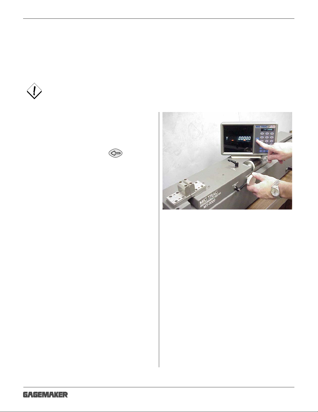
1. Mount the TF-BX setting blocks on the MIC
TRAC.
2. Apply slight pressure to hold the faces of the
anvils together. Press the key and
the display will read 0.00000.
• MIC TRAC Setting Dimensions Table
l
Page 26
BBXX//BBXXGG--11000000 SSeerriieess GGrroooovvee MMeeaassuurreemmeenntt GGaaggee OOppeerraattiioonn MMaannuuaal
26
3. Locate the dimension for the type of groove
Zeroing the BXG-1000 Gage Using the MIC TRAC (continued)
you are measuring in the MIC TRAC Setting
Dimensions table in this manual.
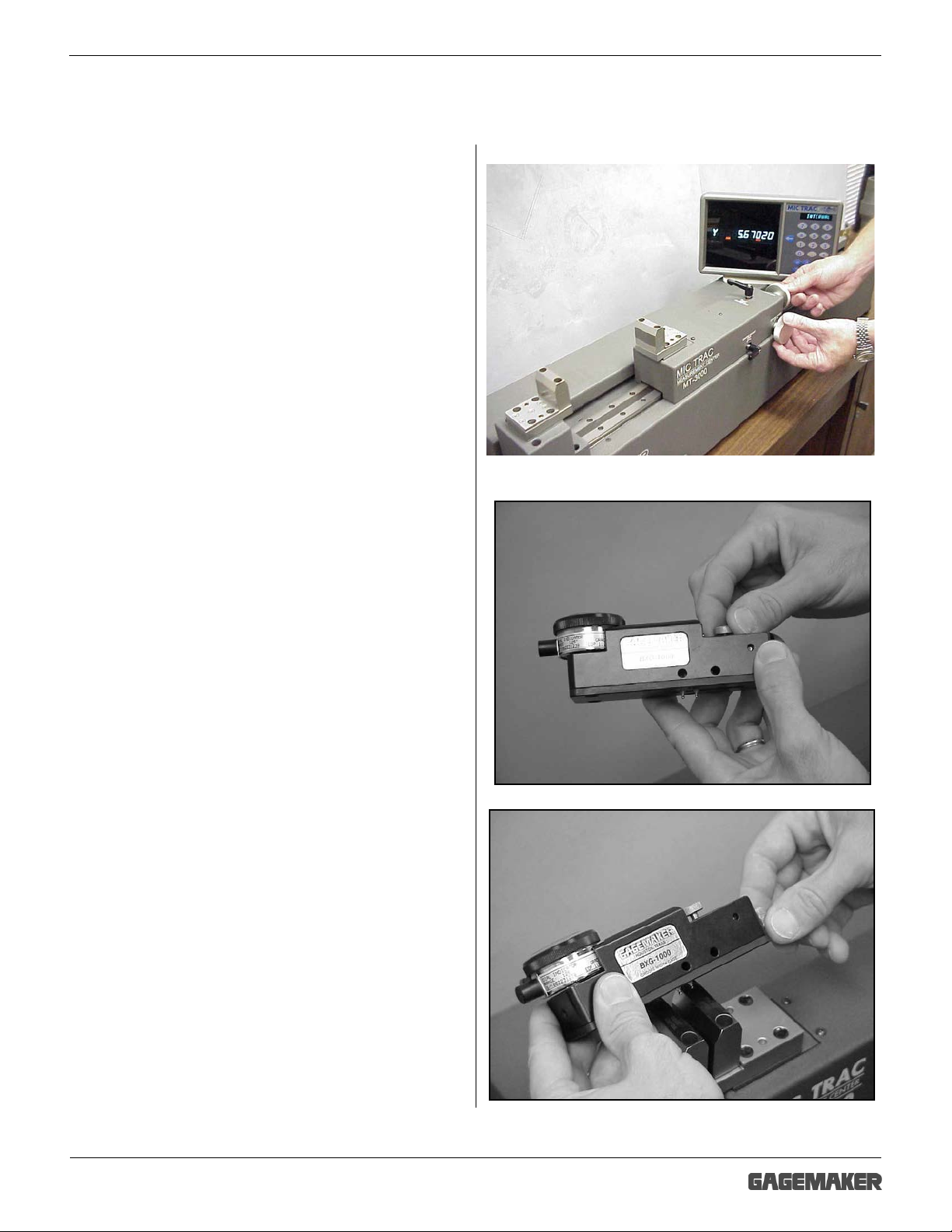
4. Turn the coarse adjust knob on the MT-3000 to
display a measurement that is close to the
desired setting dimension.
5. Secure the coarse adjust lock.
6. Turn the fine adjust knob until the CPU displays
the exact setting dimension.
7. Secure the fine adjust lock.
8. If necessary for documentation purposes, press
the PRINT pad on the CPU to record the actual
setting dimension.
l
9. Loosen the rear contact point lock knob,
located on the top of the gage.
10. Turn the contact point adjustment knob, located
at the rear of the gage, to adjust the rear
contact point.
11. Continue turning the knob to a position that
allows the BXG-1000 gage to set on the top
surfaces of the MIC TRAC setting blocks.
Page 27
BBXX//BBXXGG--11000000 SSeerriieess GGrroooovvee MMeeaassuurreemmeenntt GGaaggee OOppeerraattiioonn MMaannuuaal
27
Zeroing the BXG-1000 Gage Using the MIC TRAC (continued)
l
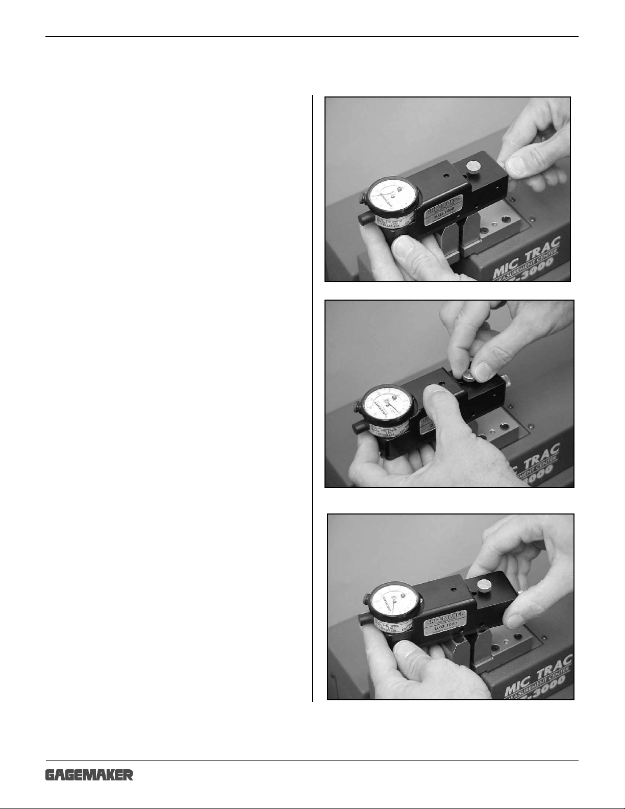
12. Place the BXG-1000 gage on the setting
blocks, positioning the contact points between
the setting blocks.
13. Adjust the rear contact point until both contact
points touch the inside of the MIC TRAC setting
blocks.
14. Continue to turn the contact point adjustment
knob until the indicator has approximately
0.010” to 0.020” of preload.
15. Tighten the rear contact point lock knob.
16. While maintaining pressure against the rear
contact point and setting block, sweep the gage
back and forth to locate the smallest indicator
reading.
Note: Use the rear contact point as a pivot.
Page 28
BBXX//BBXXGG--11000000 SSeerriieess GGrroooovvee MMeeaassuurreemmeenntt GGaaggee OOppeerraattiioonn MMaannuuaal
28
Zeroing the BXG-1000 Gage Using the MIC TRAC (continued)
l
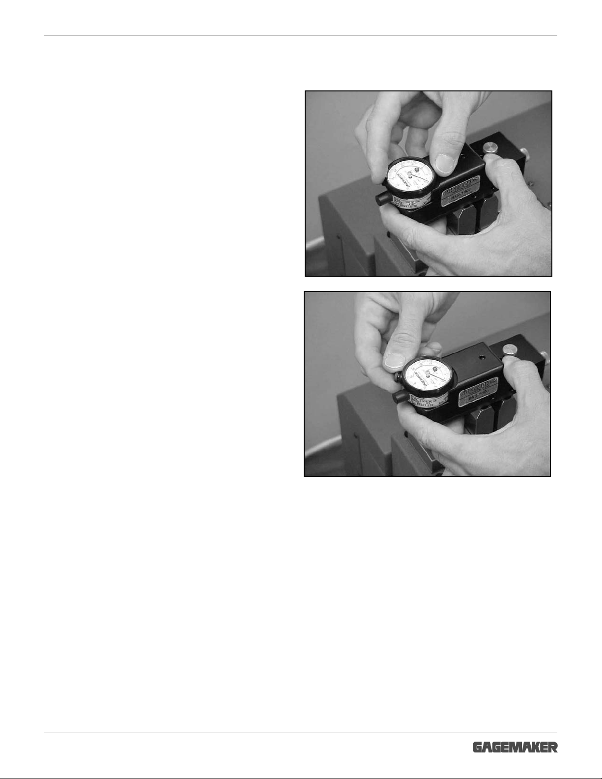
17. Turn the indicator dial on the BXG-1000 gage
to align the needle with zero.
18. Tighten the indicator clamp.
Note: Note the position of the small revolution
counter on the indicator before removing
the gage. Place a piece of masking tape on
the side of the gage and record the dial
setting of the small revolution counter to
eliminate incorrect indicator readings.
19. Set a frequency for verifying the zero setting of
all gages. As a minimum, the BXG-1000 gage
should be zeroed on the MIC TRAC once
during each shift to ensure accurate readings.
Page 29
BBXX//BBXXGG--11000000 SSeerriieess GGrroooovvee MMeeaassuurreemmeenntt GGaaggee OOppeerraattiioonn MMaannuuaal
29
2. While maintaining pressure against the rear
Operating Procedures
Inspecting Parts with the BXG-1000 Gage
Materials Needed:
• BXG-1000 gage
• Part
• Inspection report
l
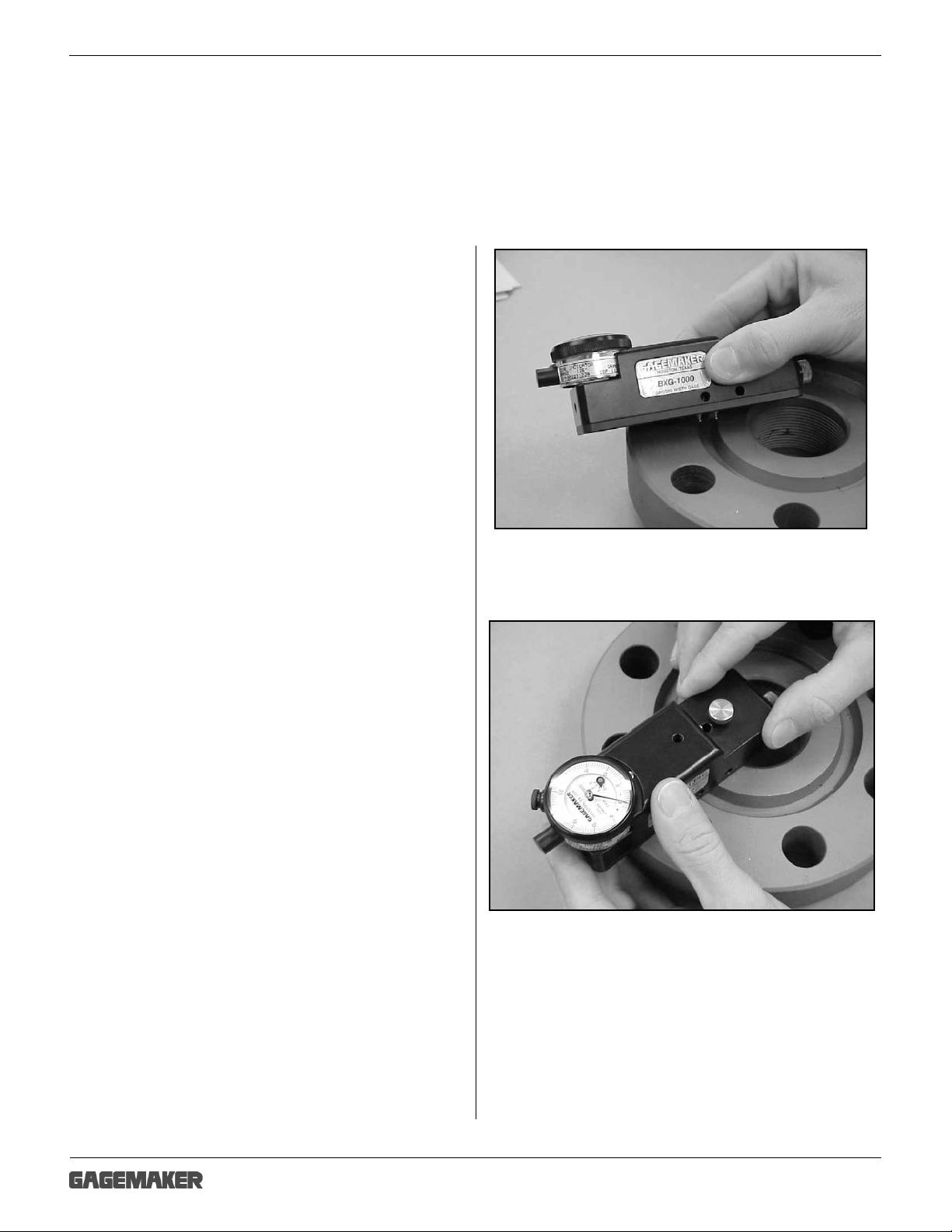
1. After zeroing the BXG-1000 gage, position the
gage on the flange face and into the ring
groove of the part, as shown.
contact point and flange face, sweep the gage
back and forth, using the rear contact point as
a pivot, to locate the smallest indicator
reading.
Note: Be sure that the small revolution counter
on the indicator is pointing to the same
number as when the gage was zeroed.
Refer to the number previously recorded
3. Repeat the process in several locations
Note: Refer to the 6B & 6BX Groove Inspection
4. Use the first part you inspected as a control
5. During the inspection process, periodically
on the side of the gage.
around the groove to get an average groove
width and record the information on an
inspection report.
Tolerances table in this manual for the
allowable groove width variation.
piece to verify repeatability. Mark the part at a
location where it was inspected and record the
deviation from zero.
place the BXG-1000 on the control piece to
verify the gage’s accuracy.
Page 30

BBXX//BBXXGG--11000000 SSeerriieess GGrroooovvee MMeeaassuurreemmeenntt GGaaggee OOppeerraattiioonn MMaannuuaal
30
l
Page 31
BBXX//BBXXGG--11000000 SSeerriieess GGrroooovvee MMeeaassuurreemmeenntt GGaaggee OOppeerraattiioonn MMaannuuaal
31
Major Diameter Variation
BX-1000 Groove Diameter Gage
Allowable Groove Width Variation
BXG-1000 Groove Width Gage
+0.013
+0.008
+0.012
+0.007 to +0.008
+0.010
+0.005 to +0.008
+0.009
+0.004 to +0.008
+0.008
+0.003 to +0.008
+0.007
+0.002 to +0.008
+0.006
+0.001 to +0.008
+0.005
0.000 to +0.008
+0.004
-0.001 to +0.008
+0.003
-0.002 to +0.008
+0.002
-0.003 to +0.007
+0.001
-0.004 to +0.006
0.000
-0.005 to +0.005
-0.001
-0.006 to +0.004
-0.002
-0.007 to +0.003
-0.003
-0.008 to +0.002
-0.004
-0.008 to +0.001
-0.005
-0.008 to +0.000
-0.006
-0.008 to -0.001
-0.007
-0.008 to -0.002
-0.008
-0.008 to -0.003
-0.010
-0.008 to -0.005
-0.011
-0.008 to -0.006
-0.012
-0.008 to -0.007
-0.013
-0.008
Major Diameter Variation
BX-1000 Groove Diameter
Allowable Groove Width Variation
BXG-1000 Groove Width Gage
6R, 6RX & 6BX Groove Inspection Tolerances
6R Groove Tolerances
+0.011 +0.006 to +0.008
l
-0.009 -0.008 to -0.004
6BX Groove Tolerances
+0.004 / -0.000 +0.004 / -0.000
Page 32
BBXX//BBXXGG--11000000 SSeerriieess GGrroooovvee MMeeaassuurreemmeenntt GGaaggee OOppeerraattiioonn MMaannuuaal
32
6BX Flange Groove Settings
6B Flange Groove Settings
Major
Settings
Minor
Settings
Major
Settings
Minor
Settings
Groove
Settings
BX-150
2.7970
2.0890
0.3411
R-RX20
2.9360
2.4400
0.2351
BX-151
2.9660
2.2260
0.3571
R-RX23
3.6230
2.8770
0.3601
BX-152
3.2990
2.4950
0.3891
R-RX24
4.1230
3.3770
0.3601
BX-153
3.9500
3.0340
0.4451
RX-25
4.2480
3.7520
0.2351
BX-154
4.5890
3.5690
0.4971
R-RX26
4.3730
3.6270
0.3601
BX-155
5.8340
4.6300
0.5891
R-RX27
4.6230
3.8770
0.3601
BX-156
9.4250
7.7750
0.8121
R-RX31
5.2480
4.5020
0.3601
BX-157
11.6780
9.7920
0.9301
R-RX35
5.7480
5.0020
0.3601
BX-158
13.9680
11.8620
1.0401
R-RX37
6.2480
5.5020
0.3601
BX-159
16.9370
14.5710
1.1701
R-RX39
6.7480
6.0020
0.3601
BX-160
15.9670
14.5870
0.6771
R-RX41
7.4980
6.7520
0.3601
BX-161
19.5080
17.8400
0.8211
R-RX44
7.9980
7.2520
0.3601
BX-162
18.7360
17.5180
0.5961
R-RX45
8.6860
7.9400
0.3601
BX-163
22.0890
20.2690
0.8971
R-RX46
8.7480
7.8780
0.4221
BX-164
22.6560
20.2680
1.1811
R-RX47
9.6850
8.3150
0.6721
BX-165
24.8080
22.8580
0.9621
R-RX49
10.9980
10.2520
0.3601
BX-166
25.4110
22.8570
1.2641
R-RX50
11.1850
10.0650
0.5471
BX-167
30.1530
28.5410
0.7931
R-RX53
13.1230
12.3770
0.3601
BX-168
30.3850
28.5410
0.9091
R-RX54
13.3100
12.1900
0.5471
BX-169
6.8590
5.7190
0.5571
R-RX57
15.3730
14.6270
0.3601
BX-170
8.6000
7.3820
0.5961
R-RX63
17.4670
15.5330
0.9541
BX-171
10.5450
9.3270
0.5961
R-RX65
18.8730
18.1270
0.3601
BX-172
13.1290
11.9110
0.5961
R-RX66
19.0600
17.9400
0.5471
BX-303
33.8530
31.8890
0.9691
R-RX69
21.3730
20.6270
0.3601
R-RX70
21.6850
20.3150
0.6721
R-RX73
23.4350
22.5650
0.4221
R-RX74
23.6850
22.3150
0.6721
R-RX82
2.6230
1.8770
0.3601
R-RX84
2.8730
2.1270
0.3601
R-RX85
3.5600
2.6900
0.4221
R-RX86
4.1230
3.0030
0.5471
R-RX87
4.4980
3.3780
0.5471
R-RX88
5.5600
4.1900
0.6721
R-RX89
5.1850
3.8150
0.6721
R-RX90
6.9350
5.3150
0.7971
R-RX91
11.4670
9.0330
1.2041
Setting Dimensions
MIC Over Ball Setting Dimensions
Use with Micrometers and Gage Blocks
Height Over Balls: .188” Diameter = .188”
.072” Diameter = .157”
l
Ring
Number
Diameter
Diameter
Groove Width
Settings
Ring
Number
Diameter
Diameter
Width
Page 33
BBXX//BBXXGG--11000000 SSeerriieess GGrroooovvee MMeeaassuurreemmeenntt GGaaggee OOppeerraattiioonn MMaannuuaal
33
312”
MIC TRAC
6BX Flange Grooves
6B Flange Grooves
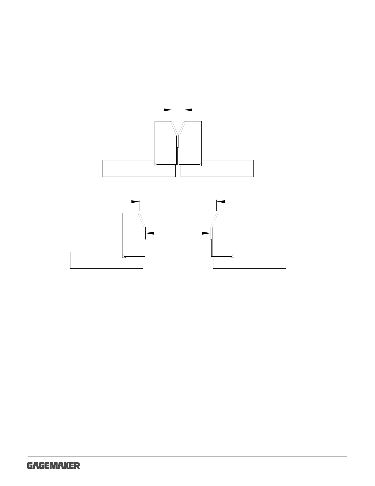
Origin of MIC TRAC Setting Dimensions
MIC TRAC TF-BX Set ting Blocks
.
(23° half angle)
l
Width Setting = API “N”-.312
Diameter Setting = API “G”-.312
Apex Dimension
Setting Dimension
Width Setting = API “F”-.312
Diameter Setting = (API “P”-.312) + API “F”
Page 34
BBXX//BBXXGG--11000000 SSeerriieess GGrroooovvee MMeeaassuurreemmeenntt GGaaggee OOppeerraattiioonn MMaannuuaal
34
Diameter
Settings
Groove Width
Settings
Diameter
Settings
Groove Width
Settings
BX-150
2.5810
0.1380
R-RX20
2.7200
0.0320
BX-151
2.7500
0.1540
R-RX23
3.4070
0.1570
BX-152
3.0830
0.1860
R-RX24
3.9070
0.1570
BX-153
3.7340
0.2420
RX-25
4.0320
0.0320
BX-154
4.3730
0.2940
R-RX26
4.1570
0.1570
BX-155
5.6180
0.3860
R-RX27
4.4070
0.1570
BX-156
9.2090
0.6090
R-RX31
5.0320
0.1570
BX-157
11.4620
0.7270
R-RX35
5.5320
0.1570
BX-158
13.7520
0.8370
R-RX37
6.0320
0.1570
BX-159
16.7210
0.9670
R-RX39
6.5320
0.1570
BX-160
15.7510
0.4740
R-RX41
7.2820
0.1570
BX-161
19.2920
0.6180
R-RX44
7.7820
0.1570
BX-162
18.5200
0.3930
R-RX45
8.4700
0.1570
BX-163
21.8730
0.6940
R-RX46
8.5320
0.2190
BX-164
22.4400
0.9780
R-RX47
9.4690
0.4690
BX-165
24.5920
0.7590
R-RX49
10.7820
0.1570
BX-166
25.1950
1.0610
R-RX50
10.9690
0.3440
BX-167
29.9370
0.5900
R-RX53
12.9070
0.1570
BX-168
30.1690
0.7060
R-RX54
13.0940
0.3440
BX-169
6.6430
0.3540
R-RX57
15.1570
0.1570
BX-170
8.3840
0.3930
R-RX63
17.2510
0.7510
BX-171
10.3290
0.3930
R-RX65
18.6570
0.1570
BX-172
12.9130
0.3930
R-RX66
18.8440
0.3440
BX-303
33.6370
0.7660
R-RX69
21.1570
0.1570
R-RX70
21.4690
0.4690
R-RX73
23.2190
0.2190
R-RX74
23.4690
0.4690
R-RX82
2.4070
0.1570
R-RX84
2.6570
0.1570
R-RX85
3.3440
0.2190
R-RX86
3.9070
0.3440
R-RX87
4.2820
0.3440
R-RX88
5.3440
0.4690
R-RX89
4.9690
0.4690
R-RX90
6.7190
0.5940
R-RX91
11.2510
1.0010
R-RX99
9.4070
0.1570
MIC TRAC Setting Dimensions
Use with Gagemaker TF-BX Setting Blocks
6BX Flange Groove Settings 6B Fl ange Groove Settings
l
Ring Number
Ring Number
Page 35

BBXX//BBXXGG--11000000 SSeerriieess GGrroooovvee MMeeaassuurreemmeenntt GGaaggee OOppeerraattiioonn MMaannuuaal
35
l
Care and Maintena nc e
Maintenance Tips
• Keep all unprotected metal surfaces coated with light oil.
• Avoid dropping the gage or subjecting it to any vibration or impact.
• Keep the gage dry and away from any machine coolant spray.
• Do not force the movement of any of the mechanical parts. The mechanics are designed to move
freely.
• Keep the indicator face clean.
Warranty Information
Gagemaker warrants its products to be free from defects in material and workmanship under normal
operating conditions for 12 months from the date of shipment. This warranty is limited to repairing, or at
Gagemaker’s option, replacing any product which is proven to have been defective at the time it was
shipped and/or suffered damage during shipping, provided buyer has given Gagemaker written notice of
any such claimed defect within 15 days of receipt. Any defect ive product must be properly packed and
shipped to the Gagemaker factory in Pasadena, Texas USA. This warranty applies to all products when
used in a normal industrial environment. Any unauthorized tampering, misuse or neglect will make this
warranty null and void. Under no circumstances will GAGEMAKER or any affiliate have any liabilities for
loss or for any indirect or consequential damages. The foregoing warranties are in lieu of all other
warranties expressed or implied, including but not limited to, the implied warranties of merchantability
and fitness for a particular purpose.
Return products for repair or calibration to:
Gagemaker LP
712 East Southmore Ave.
Pasadena, TX 77502-110
Page 36

Gagemaker, LP, P.O. Box 87709, Houston, Texas 77287-7709
712 East Southmore Ave., Pasadena, Texas 77502
Phone: 713-472-7360
Fax: 713-472-7241
Web site: www.gagemaker.com
 Loading...