

Gage CompuScope 85GC, CompuScope 3200C, CompuScope 1610C, CompuScope 14100C, CS85GC Hardware Manual And Driver Installation Manual
...
GAGE APPLIED TECHNOLOGIES
Gage CompactPCI/PXI Hardware Manual
and Driver Installation Guide
P/N: 0045509
Reorder #: MKT-HWM-cPCI02
0411

© Copyright Gage Applied Technologies 2004
Second Edition (November 2004)
GAGE, COMPUSCOPE, COMPUSCOPE 85GC, COMPUSCOPE 82GC, COMPUSCOPE 14100C, COMPUSCOPE 1610C,
C
OMPUSCOPE 3200C, GAGESCOPE, GSINST, and MULTI-CARD are registered trademarks of Gage Applied Technologies, Inc.
MS-DOS, W
Microsoft Incorporated. LabVIEW and LabWindows/CVI are registered trademarks of National Instruments. MATLAB is a
registered trademark of The MathWorks Inc. IBM, IBM PC, IBM PC/XT, IBM PC AT and PC-DOS are trademarks of
International Business Machines Corporation. All other trademarks are registered trademarks of their respective companies.
Changes are periodically made to the information herein; these changes will be incorporated into new editions of the publication.
Gage Applied Technologies, Inc. may make improvements and/or changes in the products and/or programs described in this
publication at any time. The latest manual can be found on our web page at
www.gage-applied.com in the Downloads section, User Manuals.
Copyright © 2004 Gage Applied Technologies, Inc. All Rights Reserved, including those to reproduce this publication or parts
thereof in any form without permission in writing from Gage Applied Technologies, Inc. The installation program used to install
the GageScope Software, InstallShield, is licensed software provided by InstallShield Software Corp., 900 National Parkway, Ste.
125, Schaumburg, IL. InstallShield is Copyright ©1998 by InstallShield Software Corp., which reserves all copyright protection
worldwide. InstallShield is provided to you for the exclusive purpose of installing the GageScope Software. In no event will
InstallShield Software Corp. be able to provide any technical support for GageScope. For detailed Terms and Conditions, please
refer to the GageScope User’s Guide.
Please complete the following section and keep it handy when calling Gage for technical support:
How to reach Gage Applied Technologies, Inc. for Product Support
Toll-free phone: (800) 567-GAGE Toll-free fax: (800) 780-8411
To reach Gage from outside North America
Tel: +1-514-633-7447 Fax: +1-514-633-0770
Email: prodinfo@gage-applied.com Website: www.gage-applied.com
INDOWS 95, WINDOWS 98, WINDOWS ME, WINDOWS NT, WINDOWS 2000 and WINDOWS XP are trademarks of
Owned by: ___________________________
Serial Number(s): ___________________________
___________________________
Purchase Date: ___________________________
Purchased From: ___________________________
You must also have the following information when you call:
· Software Driver & Application Version
· Software Development Kit, if applicable
· Brand name and type of computer
· Processor and bus speed
· Total memory size
· Information on all other hardware in the computer

Table of contents
Preface................................................................................................................................................................. iii
Preventing ESD .................................................................................................................................................... 1
General safety summary ....................................................................................................................................... 2
Installing single or multiple/independent CompuScope CompactPCI/PXI cards ................................................. 3
Installing CompactPCI/PXI Master/Slave multi-card systems ............................................................................. 9
Multiple Record for CompuScope 14100C and CompuScope 1610C................................................................ 19
Multiple Record for the CompuScope 82GC...................................................................................................... 20
Memory organization on CompuScopes (except for the CS85GC) .................................................................... 21
Memory organization on CompuScope 85GC.................................................................................................... 25
Driver installation guide .................................................................................................................................. 27
Section 1 – Installing drivers and applications ................................................................................................... 28
CompuScope Drivers Installation................................................................................................................... 35
CompuScope 3.82 Drivers........................................................................................................................... 36
CompuScope 3.60 Windows 98/ME or Windows 2K/XP Drivers .............................................................. 42
CompuScope 3.60 Windows NT Driver Installation ................................................................................... 43
Free Applications............................................................................................................................................ 47
Purchased Software ........................................................................................................................................ 48
GageScope ................................................................................................................................................... 49
Software Development Kits (SDKs) ............................................................................................................ 50
Section 2 – Verifying the operation of your hardware........................................................................................ 52
Verifying installation and configuration of CompuScope hardware under Windows 2000/XP with
CompuScope Manager ................................................................................................................................... 52
Verifying installation and configuration of CompuScope hardware under Windows 98/ME/NT with
GageConfig..................................................................................................................................................... 53
Verifying signal acquisition of a CompuScope card with GageScope and CSTest ........................................ 54
Section 3 – Verifying signal acquisition with CSTest+ ...................................................................................... 55
Setting-up your Hardware............................................................................................................................... 55
Running CSTest+ ........................................................................................................................................... 55
What you should receive with your CompuScope 85GC .............................................................................. 71
CompuScope 85GC compliance statement......................................................................................................... 73
CompuScope 85GC product introduction........................................................................................................... 74
CompuScope 85GC specifications ..................................................................................................................... 75
CompuScope 85GC ordering information.......................................................................................................... 78
CompuScope 85GC simplified block diagram ................................................................................................... 79
CompuScope 85GC: identifying your CompuScope card(s) .............................................................................. 80
CompuScope 85GC connectors and headers ...................................................................................................... 81
CompuScope 85GC triggering............................................................................................................................ 82
External Trigger amplifier.............................................................................................................................. 82
TV Triggering................................................................................................................................................. 82
CompuScope 85GC throughput & maximum PRF............................................................................................. 83
What you should receive with your CompuScope 82GC .............................................................................. 85
CompuScope 82GC compliance statement......................................................................................................... 87
CompuScope 82GC product introduction........................................................................................................... 88
CompuScope 82GC specifications ..................................................................................................................... 89
CompuScope 82GC ordering information.......................................................................................................... 93
CompuScope 82GC simplified block diagram ................................................................................................... 95
CompuScope 82GC: identifying your CompuScope card(s) .............................................................................. 96
CompuScope 82GC connectors and headers ...................................................................................................... 98
CompuScope 82GC triggering.......................................................................................................................... 100
External Trigger amplifier............................................................................................................................ 100
CompuScope 82GC External Clock ................................................................................................................. 101
Gage CompactPCI/PXI Hardware Manual and Driver Installation Guide i

CompuScope 82GC Trigger Output ..................................................................................................................102
Single channel mode......................................................................................................................................103
Dual channel mode........................................................................................................................................103
CompuScope 82GC - 1 GHz Bandwidth version ..............................................................................................104
CompuScope 82GC throughput & maximum PRF............................................................................................106
What you should receive with your CompuScope 14100C ..........................................................................107
CompuScope 14100C compliance statement.....................................................................................................110
CompuScope 14100C product introduction ......................................................................................................111
CompuScope 14100C specifications .................................................................................................................112
CompuScope 14100C ordering information......................................................................................................116
CompuScope 14100C simplified block diagram...............................................................................................118
CompuScope 14100C: identifying your CompuScope card(s)..........................................................................119
CompuScope 14100C connectors and headers..................................................................................................122
CompuScope 14100C triggering .......................................................................................................................124
Windowed triggering.....................................................................................................................................125
External Trigger amplifier.............................................................................................................................125
CompuScope 14100C External Clock...............................................................................................................126
CompuScope 14100C Trigger Output...............................................................................................................127
Single channel mode......................................................................................................................................127
Dual channel mode........................................................................................................................................127
CompuScope 14100C throughput & maximum PRF.........................................................................................128
What you should receive with your CompuScope 1610C ............................................................................129
CompuScope 1610C compliance statement.......................................................................................................132
CompuScope 1610C product introduction ........................................................................................................133
CompuScope 1610C specifications ...................................................................................................................134
CompuScope 1610C ordering information........................................................................................................138
CompuScope 1610C simplified block diagram.................................................................................................140
CompuScope 1610C: identifying your CompuScope card(s)............................................................................141
CompuScope 1610C connectors and headers....................................................................................................144
CompuScope 1610C triggering .........................................................................................................................146
Windowed triggering.....................................................................................................................................147
Channel 1 or 2 triggering...............................................................................................................................147
Trigger bus for Master/Slave systems............................................................................................................147
External Trigger amplifier.............................................................................................................................147
CompuScope 1610C External Clock.................................................................................................................148
CompuScope 1610C Trigger Output.................................................................................................................149
CompuScope 1610C throughput & maximum PRF...........................................................................................150
What you should receive with your CompuScope 3200C ............................................................................151
CompuScope 3200C product introduction ........................................................................................................153
CompuScope 3200C specifications ...................................................................................................................155
CompuScope 3200C ordering information........................................................................................................158
CompuScope 3200C simplified block diagram.................................................................................................159
CompuScope 3200C: identifying your CompuScope card(s)............................................................................160
CompuScope 3200C connectors and headers....................................................................................................162
CompuScope 3200C triggering .........................................................................................................................163
CompuScope 3200C digital input......................................................................................................................164
Pin layout on CS3200C connector – Single-ended, TTL/CMOS inputs........................................................164
Pin layout on CS3200C connector – Differential, ECL/PECL inputs ...........................................................165
Input comparators..........................................................................................................................................165
Front-end FPGA............................................................................................................................................166
Gage products..................................................................................................................................................167
ii Gage CompactPCI/PXI Hardware Manual and Driver Installation Guide

Preface
This manual provides detailed information on the hardware features of CompuScope CompactPCI/PXI Analog
Input and Digital Input cards. This information includes specifications, block diagrams, and connector
descriptions, as well as memory architecture.
In addition, this guide takes you through the process of installing your CompactPCI/PXI CompuScope card(s)
and describes available custom features.
Please note that this manual is not intended as a reference for PCI bus CompuScope cards. If you did not receive
the correct guide, please contact the factory for a replacement.
It is assumed that the reader is familiar with using PCs, Windows and CompactPCI
included for these topics. If you are not comfortable with these areas, it is strongly recommended that you refer
to the relevant product guides.
To maintain the accuracy of the information contained herein, we reserve the right to make changes to this
manual from time to time.
Note: For brevity, in this manual,
“CompuScope 85GC” is sometimes abbreviated as “CS85GC”
“CompuScope 82GC” is sometimes abbreviated as “CS82GC”
“CompuScope 14100C” is sometimes abbreviated as “CS14100C”
“CompuScope 1610C” is sometimes abbreviated as “CS1610C”
TM
cards. No description is
“CompuScope 3200C” is sometimes abbreviated as “CS3200C”
Gage CompactPCI/PXI Hardware Manual and Driver Installation Guide iii


Preventing ESD
Before installing or servicing this product, read the ESD information below:
CAUTION. Static discharge can damage any
!
When handling this instrument in any way that requires access to the on-board circuitry, adhere to the following
precautions to avoid damaging the circuit components due to electrostatic discharge (ESD).
1. Minimize handling of static-sensitive circuit boards and components.
2. Transport and store static sensitive modules in their static protected containers or on a metal rail. Label
any package that contains static sensitive boards.
3. Discharge the static voltage from your body by wearing a grounded antistatic wrist strap while handling
these modules and circuit boards. Do installation and service of static-sensitive modules only at a
static-free work station.
4. Nothing capable of generating or holding a static charge should be allowed on the work station surface.
5. Handle circuit boards by the edges when possible.
6. Do not slide the circuit boards over any surface.
semiconductor component in this instrument.
7. Avoid handling circuit boards in areas that have a floor or work-surface covering capable of generating
a static charge.
Preventing ESD 1

General safety summary
Review the following safety precautions to avoid injury and prevent damage to this product or any products
connected to it. To avoid potential hazards, use this product only as specified.
Observe all terminal ratings.
To avoid fire or shock hazard, observe all ratings and markings on the product. Consult the product manual for
further ratings information before making connections to the product.
Do not apply a potential to any terminal, including the common terminal, which exceeds the maximum rating of
that terminal.
Do not operate with suspected failures.
If you suspect there is damage to this product, have it inspected by qualified service personnel.
Do not operate in wet/damp conditions.
Do not operate in an explosive atmosphere.
2 General safety summary

Installing single or multiple/independent CompuScope CompactPCI/PXI cards
In this section, we will go over a simple, step-by-step procedure for installing a single CompactPCI/PXI
CompuScope card in your CompactPCI system.
If you have purchased 2 or more cards for a Multiple/Independent system, simply repeat steps 2 to 7 (inclusively)
as many times as needed to install all of your cards. Note that current versions of GageScope software can
display channels from only one multiple-independent card in the same window. GageScope will automatically
open one separate display window for each enabled CompuScope.
Before installing the CompuScope card, please refer to page 1 for Electrostatic Discharge (ESD) handling
procedures.
Power off your CompactPCI chassis.
1
CompuScope cards are not hot-swappable and all installation and removal must be done with the power
off.
Select the required number of unused full-sized 6U CompactPCI expansion slots.
2
You need one slot for the following cards: CompuScope 82GC; CompuScope 85GC;
CompuScope 14100C-1M; CompuScope 1610C-1M, CompuScope 3200C-2MB.
You will need two slots for the following cards with 8M or more memory: CompuScope 1610C,
CompuScope 14100C, or CompuScope 3200C.
There is no limitation on which slot is used, as the CompuScope card will operate correctly in any slot.
FOR HIGHEST SIGNAL FIDELITY, IT IS RECOMMENDED THAT THE COMPUSCOPE CARD BE
INSTALLED AT LEAST ONE SLOT AWAY FROM A HIGH FREQUENCY NOISE SOURCE, SUCH AS
A POWER SUPPLY OR CPU CARD.
Installing single or multiple/independent CompuScope CompactPCI/PXI cards 3

Unfasten the screw holding the unused slot’s frontplate and remove it. For the following cards
3
with 8M or more memory: CompuScope 1610C, CompuScope 14100C, or CompuScope 3200C,
remove two adjacent frontplates.
Figure 1: Unscrew the slot’s frontplate and remove it
4 Installing single or multiple/independent CompuScope CompactPCI/PXI cards

Open the card handles.
4
This is essential for the card to slide into the CompactPCI slot. If these handles are closed, gently press
on the red tabs. This action will cause the handles to open.
Please note that the connectors in the illustration below may not be identical to your CompuScope card.
We are using a CompuScope 14100C for this example, but the card handles work the same way on all the
CompuScope CompactPCI/PXI cards.
Figure 2: Open the card handles (CS14100C shown)
Installing single or multiple/independent CompuScope CompactPCI/PXI cards 5

Insert the CompuScope card into the empty slot.
5
Ensure that the card slides into the card guides on the chassis.
Some CompactPCI chassis have air deflectors installed in unused slots. If the card does not insert in the
chassis, check for and remove the air deflector before inserting the card.
Figure 3: Inserting a single-slot CompactPCI CompuScope card
(CS85GC, CS82GC, CS14100C-1M, CS1610C-1M or CS3200C-2M)
Figure 4: Inserting a 2-slot CompactPCI CompuScope card
(CS14100C-8M and up, CS1610C-8M and up or CS3200C-256M and up)
6 Installing single or multiple/independent CompuScope CompactPCI/PXI cards

Fully slide the card into the chassis.
6
Gently push the card into the chassis until you hear the handles click into position. If necessary, provide
manual assistance in the proper closure of the handles.
Please note that the connectors in the illustration below may not be identical to your CompuScope card.
We are using a CompuScope 14100C for this example, but the card handles work the same way on all the
CompuScope CompactPCI/PCI cards.
Figure 5: Slide the card until the handles click (CS14100C shown)
Fasten the card to the chassis using the screws embedded in the card handles.
7
Figure 6: Fasten the card to the chassis using screws (CS14100C shown)
Installing single or multiple/independent CompuScope CompactPCI/PXI cards 7

Turn on the power switch of the CompactPCI chassis.
8
Install software drivers.
9
Refer to the section within this manual called Driver installation guide for instructions on installing
Windows drivers for the CompuScope cards. Windows drivers are supplied with the product on CD.
Verify presence of the CompuScope card using the configuration utility provided with the drivers.
10
Refer to the section within this manual called Driver installation guide.
(Optional) Verify the operation of the card using CSTest+ or CSTest.
11
CSTest+ and CSTest are sample programs provided with the CompuScope drivers to ensure proper
operation of the CompuScope cards. CSTest+ is provided with the 3.82.xx drivers and CSTest is
provided with the 3.60.xx drivers. Please refer to the section within this manual called Section 3 –
Verifying signal acquisition with CSTest+ for details on running CSTest+.
Install GageScope software for CS85GC, CS82GC, CS14100C and CS1610C.
12
Refer to the section within this manual called GageScope in the Driver installation guide section for
instructions on installing this software.
If you have a CS3200C, install GageBit software.
Refer to the section within this manual called Free Applications in the Driver installation guide section
for instructions on installing this software.
Run GageScope software and start acquiring data (not applicable for CS3200C).
13
Follow the instructions provided in the GageScope manual for using this software.
(Optional) Writing your own program using Gage Software Development Kits (SDKs).
14
When writing your own program using one of Gage’s Software Development Kits (SDKs), please refer to
the appropriate Gage SDK manual for information on installation and operation of the Gage SDK.
8 Installing single or multiple/independent CompuScope CompactPCI/PXI cards

Installing CompactPCI/PXI Master/Slave multi-card systems
Below, you will find detailed instructions to guide you through the installation process of your Master/Slave
Multi-Card system.
Before installing the CompuScope cards, please refer to page 1 for Electrostatic Discharge (ESD) handling
procedures.
Please note that, unlike other types of CompuScope cards, multiple CS85GC cards cannot be configured as a
Master/Slave Multi-Card system. Multi-Card CompuScope 85GC systems must be installed and operated as a
Multiple-Independent Multi-Card system.
If you are installing a Multiple/Independent system, follow the instructions listed in the previous section,
Installing single or multiple/independent CompuScope CompactPCI/PXI , for installing each of the cards.
Power off your CompactPCI chassis.
1
CompuScope cards are not hot-swappable and all installation and removal must be done with the power
off.
Select adjacent full-sized 6U CompactPCI expansion slots.
2
If you are installing a Master/Slave system consisting of CompuScope 82GC, CompuScope 14100C-1M,
CompuScope 1610C-1M or CompuScope 3200C-2MB cards, the number of adjacent slots should be
equal to the number of CompuScope cards you want to install.
If you are installing a Master/Slave system consisting of the following CompuScope cards with 8M or
more memory: CompuScope 14100C, CompuScope 1610C, CompuScope 3200C, the number of
adjacent slots should be twice the number of CompuScope cards you want to install.
There is no limitation on which slots are used, as the CompuScope cards will operate correctly in any
slot.
FOR HIGHEST SIGNAL FIDELITY, IT IS RECOMMENDED THAT COMPUSCOPE CARDS BE
INSTALLED AT LEAST ONE SLOT AWAY FROM A HIGH FREQUENCY NOISE SOURCE,
SUCH AS A POWER SUPPLY OR CPU CARD
Installing CompactPCI/PXI Master/Slave multi-card systems 9

3
Unscrew the screws holding the unused slots’ frontplates and remove them.
For the following cards with 8M or more memory: CompuScope 1610C, CompuScope 14100C, or
CompuScope 3200C, remove two adjacent frontplates.
Figure 7: Unscrew the slot’s frontplate and remove it
10 Installing CompactPCI/PXI Master/Slave multi-card systems

Open the card handles of all CompuScope cards.
4
This is essential for the cards to slide into the CompactPCI slot. If these handles are closed, gently press
on the red tabs. This action will cause the handles to open.
Please note that the connectors in the illustration below may not be identical to your CompuScope card.
We are using a CompuScope 14100C for this example, but the card handles work the same way on all the
CompuScope CompactPCI/PCI cards.
Figure 8: Open the card handles (CS14100C shown)
Installing CompactPCI/PXI Master/Slave multi-card systems 11

5
Insert the MASTER CompuScope card into the left-most empty slot.
Note that the MASTER card is the one labeled “CH 1” & “CH 2”. Ensure that the card slides into the
card guides on the chassis.
Some CompactPCI chassis have air deflectors installed in unused slots. If the card does not insert in the
chassis, check for and remove the air deflector before inserting the card.
Figure 9: Inserting the MASTER card (CS14100C shown)
12 Installing CompactPCI/PXI Master/Slave multi-card systems

Fully slide the card into the chassis.
6
Gently push the card into the chassis until you hear the handles click into position. If necessary, provide
manual assistance in the proper closure of the handles.
Please note that the connectors in the illustration below may not be identical to your CompuScope card.
We are using a CompuScope 14100C for this example, but the card handles work the same way on all the
CompuScope CompactPCI/PCI cards.
Figure 10: Slide the card until the handles click (CS14100C shown)
Installing CompactPCI/PXI Master/Slave multi-card systems 13

7
Fasten the card to the chassis using the screws embedded in the card handles.
Figure 11: Fasten the card to the chassis using screws (CS14100C shown)
14 Installing CompactPCI/PXI Master/Slave multi-card systems

Repeat steps 5 through 7 for the SLAVE cards.
8
Make sure you maintain consecutive channel numbering. Slave Cards must be installed into slots on the
right side of the Master card.
Figure 12: Insert all Slave cards (CS14100C shown)
Installing CompactPCI/PXI Master/Slave multi-card systems 15

9
Attach the Master/Slave Timing Module (MSTM) to the cards.
Plug the MSTM to the front panel of the CompuScope cards and then attach the MSTM to the
CompuScope cards using the screws provided with the MSTM.
The MSTM can only be inserted into the installed Master/Slave Set in one orientation. Do not force.
The text on the MSTM label should be right side up.
10
11
12
13
14
Figure 13: Attach the Master/Slave Timing Module (CS14100C shown)
Turn on the power switch of the CompactPCI chassis.
Install software drivers.
Refer to the section within this manual called Driver installation guide for instructions on installing
Windows drivers for the CompuScope cards. Windows drivers are supplied with the product on CD.
Verify presence of the CompuScope card using the configuration utility provided with the drivers.
Refer to the section within this manual called Driver installation guide.
(Optional) Verify the operation of the card using CSTest+ or CSTest.
CSTest+ and CSTest are sample programs provided with the CompuScope drivers to ensure proper
operation of the CompuScope cards. CSTest+ is provided with the 3.82.xx drivers and CSTest is
provided with the 3.60.xx drivers. Please refer to the section within this manual called Section 3 –
Verifying signal acquisition with CSTest+ for details on running CSTest+.
Install GageScope software for CS82GC, CS14100C and CS1610C.
Refer to the section within this manual called GageScope in the Driver installation guide section for
instructions on installing this software.
If you have a CS3200C, install GageBit software.
Refer to the section within this manual called Free Applications in the Driver installation guide section
for instructions on installing this software.
16 Installing CompactPCI/PXI Master/Slave multi-card systems

Run GageScope software and start acquiring data (not applicable for CS3200C).
15
Follow the instructions provided in the GageScope manual for using this software.
(Optional) Writing your own program using Gage Software Development Kits (SDKs).
16
When writing your own program using one of Gage’s Software Development Kits (SDKs), please refer
to the appropriate Gage SDK manual for information on installation and operation of the Gage SDK.
Installing CompactPCI/PXI Master/Slave multi-card systems 17

Notes
18 Installing CompactPCI/PXI Master/Slave multi-card systems
Multiple Record for CompuScope 14100C and CompuScope 1610C
Please note: the CompuScope 85GC and CompuScope 3200C do not support Multiple Record.
See next page for details on Multiple Record for the CompuScope 82G.
Even though the CompactPCI bus allows very fast data throughput to system RAM, there may still be
applications in which data bursts cannot be off-loaded either because of very fast trigger repeat frequency or
because of software limitations.
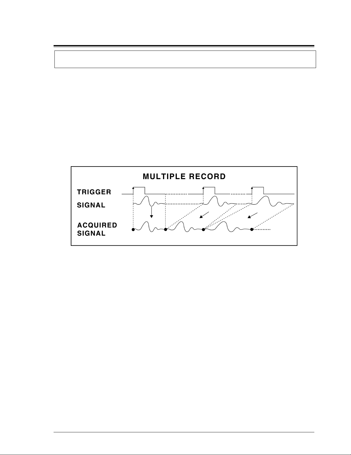
Multiple Recording allows the CompuScope card to capture data on successive triggers and stack it in the onboard memory.
It should be noted that only post-trigger data can be captured in Multiple Record mode.
GageScope software can display the stacked data as individual acquisitions. Software drivers also provide
support for accessing Multiple Record data.
Once the CompuScope card has finished capturing a Multiple Record segment, the trigger circuitry is
automatically re-armed within 16 sample clock cycles to start looking for the next trigger. No software
intervention is required.
Figure 14: Multiple Record mode
Multiple Recording is useful for applications in which a series of bursts of data have to be captured in quick
succession and there is not enough time to off-load the data to the system RAM.
Another situation in which Multiple Recording may be used is when data storage has to be optimized. These are
cases in which only certain portions of the incoming signal are of interest and data capture during the dead time
between successive portions is not useful.
Examples of these situations are radar pulses, ultrasound data, lightning pulses, imaging signals and explosion
testing.
Multiple Record for CS14100C & CS1610C 19

Multiple Record for the CompuScope 82GC
Even though the CompactPCI bus allows very fast data throughput to system RAM, there may still be
applications in which data bursts cannot be off-loaded either because of very fast trigger repeat frequency or
because of software limitations.
Multiple Recording allows CompuScope 82GC to capture data on successive triggers and stack it in the on-board
memory. The minimum record size is 256 samples in dual channel mode and 512 samples in single channel
mode. CompuScope 82GC models with 16M acquisition memory provide up to 21,845 records which can be
captured in Multiple Record mode.
The CompuScope 82GC is capable of capturing pre-trigger data in Multiple Record mode. Software can
configure the CompuScope 82GC to capture between 0 to 32K points of pre-trigger data.
GageScope software can display the stacked data as individual acquisitions. Software drivers also provide
support for accessing Multiple Record data.
Once the CompuScope 82GC has finished capturing a Multiple Record segment, the trigger circuitry is
automatically re-armed within 152 (304) sample clock cycles in dual (single) channel mode to start looking for
the next trigger. No software intervention is required. This is required to ensure that the necessary pre-trigger
data is acquired. That is, data is acquired during this time, however, the trigger is only enabled once the
pre-trigger data has been recorded.
Figure 15: Multiple Record mode with Pre-Trigger data
Multiple Recording is useful for applications in which a series of bursts of data have to be captured in quick
succession and there is not enough time to off-load the data to the system RAM.
Another situation in which Multiple Recording may be used is when data storage has to be optimized. These are
cases in which only certain portions of the incoming signal are of interest and data capture during the dead time
between successive portions is not useful.
Examples of these situations are radar pulses, ultrasound data, lightning pulses, imaging signals and explosion
testing.
20 Multiple Record for CS82GC

Memory organization on CompuScopes (except for the CS85GC)
Please note: for memory organization on the CompuScope 85GC, please refer to the next section.
Memory architecture
CompuScope cards have high-speed on-board memory to store the digital data for the CompactPCITM bus to
access it in post-processing mode.
Interface to the CompactPCITM bus
In order to allow optimum data transfer rates from the CompuScope card memory to the PC memory, the
on-board RAM is mapped into the memory space of the CompactPCI
The exact address at which this memory is mapped is determined by the CompactPCI
means that the user does not have to set any jumpers or switches to configure the CompuScope card—it really is
plug and play.
Bus Mastering mode
Full Bus Mastering capabilities are provided on CompuScope cards, allowing the fast data transfer to occur as a
result of a Direct Memory Access (DMA).
TM
bus.
TM
Plug-n-Play BIOS. This
Software loads the start address, destination pointer and number of points to be transferred into the
CompactPCI
CompactPCI
TM
bus controller on the CompuScope card and then asks the card to do a DMA transfer. The
TM
bus mastering control circuitry takes over from this point and performs the transfer without any
CPU involvement.
Data storage
The data coming out of the A/D converters or digital input is stored in the on-board memory buffer, which is
configured as a circular buffer. A circular buffer is used to guarantee that the system will keep on capturing data
indefinitely until a trigger event is detected.
The sequence of events is as follows:
• CompactPCI
• The CompuScope sets BUSY flag. CompactPCI
memory.
• The on-board memory counters initialize to ZERO and start counting up, thereby starting data storage at
memory address ZERO.
• The system waits for a trigger event to occur while it is storing data in the on-board memory. This data is
called Pre-Trigger data.
• Once the trigger event is received, a specified number of Post-Trigger points are captured. The number of
Post-Trigger Points can be specified by writing to a register on the CompuScope.
• After storing the specified number of Post-Trigger Points subsequent to receiving the trigger event,
acquisition is stopped, BUSY flag is reset and PC bus is allowed access to the on-board memory.
TM
bus tells the CompuScope to start_capture using a register bit.
TM
bus is denied any further access to the on-board
Memory organization on CompuScopes (except for CS85GC) 21

A graphical representation of the above sequence is as follows:
Figure 16: Pre-Trigger: all data points in buffer valid
In the diagram above, the circular memory buffer is shown as a ring with the physical memory address ZERO at
the top. Data storage is shown as a spiraling line going clockwise.
Storage starts at address ZERO and keeps on writing into the memory until it is filled (the spiraling line
completes a circle) and then starts overwriting the data stored in addresses ZERO, 1, 2...
Once a trigger event is detected, the address to which the data was being written into is tagged as the Trigger
Address, a specified number of Post-Trigger points are captured and then the acquisition is stopped.
The memory address at which the acquisition is stopped is designated as the End Address and the address after
that one is called Start Address.
Now, Pre-Trigger data lies between Start Address and Trigger Address, and Post-Trigger data between Trigger
Address and End Address.
It is clear from the diagram shown above that memory address ZERO is not necessarily the first point, or Start
Address, of the signal being captured. In fact, the physical address ZERO has very little significance in such a
system, as the trigger can happen at any time.
One case in which ZERO is the Start Address is when a trigger is received before the memory had filled up, i.e.
the trigger was received right after the software tells the CompuScope to start_capture.
22 Memory organization on CompuScopes (except for CS85GC)

This situation is illustrated below:
Figure 17: Pre-Trigger: not all data points in buffer valid
This condition can be detected by looking at the RAMFULL bit in the STATUS register. This bit is reset to
ZERO when a start_capture command is issued and is set to ONE when the memory counters overflow from
FFFFF to ZERO, for example.
In this case, Pre-Trigger data lies between ZERO and Trigger Address, and Post-Trigger between Trigger
Address and End Address.
These issues are handled seamlessly by the driver and the Software Development Kits (SDKs).
Memory organization on CompuScopes (except for CS85GC) 23

Notes
24 Memory organization on CompuScopes (except for CS85GC)

Memory organization on CompuScope 85GC
FISO memory architecture
CompuScope 85GC uses a very unique memory system that uses on-chip analog memory cells that can store the
instantaneous value of the input voltage at a particular time.
By using 10,000 such cells for each of the input channels, CompuScope 85GC can offer acquisition depth of
10,000 points per channel.
This “analog storage data” is then converted to digital codes using a very accurate, but slower speed A/D
converter to yield very fast sampling speed at an unprecedented price.
Hence the name, Fast In Slow Out.
On-board error correction and calibration
Not surprisingly, the analog memory cells on the CompuScope 85GC are not absolutely accurate from one
device to another. As such, it is necessary for each CompuScope 85GC to be calibrated.
All error correction and calibration is performed by very powerful signal processors, including custom ASICs,
on-board the CompuScope 85GC.
Interface to the CompactPCITM bus
In order to allow optimum data transfer rates from the CompuScope 85GC acquisition memory to the PC
memory, the on-board circuitry uses DMA to move the data from the memory of the on-board calibration
processors into PCI memory.
CompactPCI
to worry about setting any jumpers or switches to configure the CS85GC.
TM
Plug-n-Play BIOS is fully supported by CompuScope 85GC, making it unnecessary for the user
A/D data storage
FISO memories are configured as circular buffers. A circular buffer is used to guarantee that the system will keep
on capturing data indefinitely until a trigger event is detected.
The sequence of events is as follows:
• CompactPCI
• BUSY flag is set by the CompuScope. CompactPCI
memory.
• The on-board FISO memory counters initialize to ZERO and start counting up, thereby starting data storage
at memory address ZERO.
• The system waits for a trigger event to occur while it is storing data in the on-board memory. This data is
called Pre-Trigger data.
• Once the trigger event is received, a specified number of Post-Trigger points are captured. The number of
Post-Trigger Points can be specified by writing to a register on the CompuScope.
• After storing the specified number of Post-Trigger Points subsequent to receiving the trigger event,
acquisition is stopped, BUSY flag is reset and PC bus is allowed access to the on-board memory.
TM
bus tells the CompuScope to start_capture using a register bit.
TM
bus is denied any further access to the on-board
CompuScope 85GC memory organization 25

A graphical representation of the above sequence is as follows:
Figure 18: Pre-Trigger: all data points in buffer valid
In the diagram above, the circular memory buffer is shown as an annulus with the physical memory address
ZERO at the top. Data storage is shown as a spiraling line going clockwise.
Storage starts at address ZERO and keeps on writing into the memory until it is filled (the spiraling line
completes a circle) and then starts overwriting the data stored in addresses ZERO, 1, 2...
Once a trigger event is detected, the address to which the data was being written into is tagged as the Trigger
Address, a specified number of Post-Trigger points are captured and then the acquisition is stopped.
The memory address at which the acquisition is stopped is designated as the End Address and the address after
that one is called Start Address.
Now, Pre-Trigger data lies between Start Address and Trigger Address, and Post-Trigger data between Trigger
Address and End Address.
It is clear from the diagram shown above that memory address ZERO is not necessarily the first point, or Start
Address, of the signal being captured. In fact, the physical address ZERO has very little significance in such a
system, as the trigger can happen at any time.
26 CompuScope 85GC memory organization

Driver installation guide
Installing your Gage hardware in a computer is only one step in setting up your system. You also need to install
drivers and application software to operate the instrument card or cards you purchased. This section will
describe how to install software and verify the operation of your new hardware.
Please note that due to the various versions of operating systems supported by Gage, the screen captures serving
as illustrations in this manual may differ from what you will see on your screen. The discrepancies will not be
material when it comes to basic functionalities and operation; however, the look and certain names will be
slightly different.
Driver installation guide 27

Section 1 – Installing drivers and applications
The product you bought comes with a totally re-designed and vastly improved installation package. This new
installer was designed to work the same way on all supported operating systems. It was also designed to be
intuitive to most users and easy to follow for anyone familiar with installing software on a computer running
Windows. Therefore a certain level of familiarity with the Windows operating system is assumed in this manual.
The basic instructions presented in this section should be sufficient for most installation needs.
The main installation steps are as follows: (you may skip some of the steps if you do not wish or need to install
certain drivers or applications)
A – If you have not already done so, insert your Gage Software CD into the CD-ROM drive of your computer.
The AutoRun feature of Windows should kick-in and bring up the installer’s main screen. If this does not take
place, you can start the installer by double-clicking on the gage.exe item that you will find on the CD.
The Gage software disk main screen will appear (see Figure 19 below).
Figure 19: The Gage Software Disk’s main screen
This window offers four possible options (not counting the Exit option):
• Install Software
• Browse CD
• Contact Gage
• About CD
The fourth option, About CD, is an important first step whenever troubleshooting the installation or asking for
technical support from Gage. It provides valuable information about the various software drivers and application
28 Driver installation guide

packages available on the CD. Figure 20 gives an example from the first version of this new installation
package.
Figure 20: The About CD screen
Whenever navigating the installation software, you can use the Back button at the bottom-right of the screen to
return to a previous screen in the installation hierarchy.
Figure 21: The Back button
Driver installation guide 29

Another useful feature of the installer is the Contact Gage option available from the Gage Software Disk’s main
screen. From this screen, you will find useful contact information for Gage for technical support.
Figure 22: The Contact screen
Also from the Gage Software Disk’s main screen, you can directly access Gage’s Web site by clicking on the
Web address under the Gage logo.
Figure 23: The link to Gage’s Web site on the Gage Software Disk’s main screen
30 Driver installation guide

Finally, as a last exploratory step before installing, you can click on the Browse CD button to open a Windows
Explorer window showing the content of the Gage Software Disk (see Figure 24 below).
Figure 24: Browsing the CD
Now that you have become familiar with the first level of the installer, we can proceed with the installation
proper.
Driver installation guide 31

B – Click on the Install Software button to start installing the Gage software.
The Install Software screen (Figure 25) offers four software options to install:
• CompuScope drivers
• CompuGen drivers
• Free applications
• Purchased software
Figure 25: The Install Software screen
32 Driver installation guide

As you position the mouse over one of the four menu options, details of each option appear in a text box to the
right of the screen (see Figure 26):
Figure 26: Example of information visible when positioning the mouse on a menu item
Driver installation guide 33

If you wish to leave the Install Software screen without installing any software, simply click the Back button to
go back to the Gage Applied Technologies screen.
Once you are back to the main Gage Software Disk screen, click on the Exit button located at the bottom right of
the screen. The last screen you will see upon exiting is shown below (Figure 27).
Figure 27: Splash screen seen upon exiting the installer
34 Driver installation guide

CompuScope Drivers Installation
Click on the CompuScope drivers button to go to the CompuScope drivers screen (Figure 28). The installer
offers two choices of drivers; you must choose according to the type of hardware you purchased.
Figure 28: CompuScope Drivers for Win2K/WinXP
Since the CompuScope Windows 98/ME and Windows 2K/XP drivers are plug-and-play, we recommend that
you first install your CompuScope hardware and then use the Add New Hardware function of your operating
system (if the system does not automatically prompt you for the location of the driver) to install the CompuScope
drivers.
Driver installation guide 35

CompuScope 3.82 Drivers
For the CompuScope 3.82 drivers, it is possible to install directly from the Gage Software disk. To start the
installation, click on CompuScope 3.82 Drivers from the Software Install option of the Gage Software Disk:
Figure 29: CompuScope Drivers for Win2K/WinXP
36 Driver installation guide

The following InstallShield Wizard screen appears:
Figure 30: InstallShield wizard
Click Next to continue with the installation of the CompuScope 3.82 drivers. Carefully read the Software and
Documentation License Agreement text as shown below.
Figure 31: License agreement text
Driver installation guide 37

To continue with the installation, you must agree with the terms in the license agreement. Otherwise, the
installation will be aborted.
Figure 32: Customer information
Enter your user information in the Customer Information screen. By default, all program features will be
installed. Alternately, you can choose the Custom option to install only specific program features.
Figure 33: Installation setup
38 Driver installation guide

The CompuScope 3.82 drivers will be installed in the O/S system drive:\Program Files\Gage\CompuScope 3.82
directory by default. You can optionally install the software into a directory of your choice.
Figure 34: Destination folder for CompuScope 3.82 drivers
Click on Install to begin the installation.
Figure 35: Begin installation
Driver installation guide 39

Clicking on Cancel at anytime will abort the driver installation.
Figure 36: Installing drivers
Click on Finish to complete the installation.
Figure 37: Installation successfully completed
40 Driver installation guide

In order to use the CompuScope Drivers, you must restart your computer. You will be asked whether or not you
want to restart your computer immediately, or you may choose to restart your computer later.
Driver installation guide 41

CompuScope 3.60 Windows 98/ME or Windows 2K/XP Drivers
For the CompuScope 3.60 Windows 98/ME or Windows 2K/XP drivers, you will actually see the following
message (Figure 38) if you try to install from this screen:
Figure 38: Plug-n-Play CompuScope driver message
The installation of the CompuScope 3.60 Windows 98/ME or Windows 2K/XP drivers should therefore be done
from the Add New Hardware function of Windows (note that the CompuScope 3.82 drivers are not available for
Windows 98/ME). To complete the installation of CompuScope drivers you will only have to point Windows to
the Gage Software Disk and Windows will do the rest of the work.
42 Driver installation guide

CompuScope 3.60 Windows NT Driver Installation
Note that if you are using Windows NT, the Add New Hardware function is not available. In order to install the
CompuScope 3.60 drivers (note that the CompuScope 3.82 drivers are not available for Windows NT), you must
run the Setup.exe file found in the CompuscopeDev/Legacy/WinNT/ directory on the Gage Software Disk:
Figure 39: WinNT Explorer window
Running the Setup.exe file will start the InstallShield Wizard for the CompuScope Win NT drivers. Click on
Next from the InstallShield Welcome screen to continue with the installation:
Driver installation guide 43

Figure 40: InstallShield Wizard for CompuScope WinNT Drivers
You will then need to choose a destination directory on your computer where you want the drivers to be
installed. By default, the drivers will be installed in the O/S system drive:\Gage\CompuScope SDK for Windows
directory. Alternately, you can choose a destination directory of your preference. Click on Next to continue
with the installation:
Figure 41: Installation setup
44 Driver installation guide

You will be prompted to view the ReadMe file during the installation.
Figure 42: View ReadMe file during installation
The following screen appears if you click Yes to view the ReadMe file:
Figure 43: ReadMe file for CompuScope Win NT drivers
Driver installation guide 45

If you prefer not to read the ReadMe file, click No and the driver installation completes. In order to use the
CompuScope Drivers, you must restart your computer. You will be asked whether or not you want to restart
your computer immediately, or you may choose to restart your computer later:
Figure 44: Installation Complete
46 Driver installation guide

Free Applications
You can install Free Applications by clicking on the Free Applications button from the Install Software screen.
Depending on the type of hardware you purchased from Gage, you may need some of these free applications to
operate your card or cards.
Figure 45: Selection of free applications from Gage
If you have bought a digital capture product from Gage, you should install the GageBit Application. To do so,
simply click on the appropriate button on the screen shown in Figure 45 above and follow the instructions of the
GageBit Install Wizard.
Driver installation guide 47

Purchased Software
Purchased Software is similarly accessed from the Install Software screen by clicking on the Purchased Software
button. There are two main categories of Purchased Software available from the Gage Software Disk:
GageScope and Software Development Kits (see Figure 46 below).
Figure 46: Selection of free applications from Gage
Clicking to install one of the software packages will bring up an install Wizard as usual; simply follow the
instructions on screen to install your software. Make sure you have your software key or keys handy as you
begin the installation process for GageScope or one of the Software Development Kits.
48 Driver installation guide

GageScope
Figure 47 shows the first screen of the GageScope Install Wizard.
Figure 47: GageScope Install Wizard
For more details on the GageScope installation, please refer to the GageScope Manual that is included in PDF
format on the Gage Software Disk (CD Drive:/Gage/SW Manuals).
Driver installation guide 49

Software Development Kits (SDKs)
The Software Development Kits (SDKs) also have standardized installation procedures and therefore will not be
covered in detail in this manual. Note that all SDKs from Gage are available from the Gage Software CD:
C/C++, MATLAB, LabVIEW and LabWindows/CVI.
The first two screens of the SDK Install Wizard are shown below.
Figure 48: First screen of the SDK Install Wizard
50 Driver installation guide

Figure 49: Second screen of the SDK Install Wizard
IMPORTANT NOTE:
If you have purchased a Software Development Kit, or if you are trying to install GageScope, you must first
install the drivers for your hardware in order to use the software. If you do not install the drivers, the sample
programs will not work properly and GageScope will only function in Demo Mode.
Driver installation guide 51

Section 2 – Verifying the operation of your hardware
Verifying installation and configuration of CompuScope hardware under Windows 2000/XP with CompuScope Manager
If you wish to verify installation and configuration of your CompuScope cards under Windows 98/ME/NT,
please refer to the next section: Verifying installation and configuration of CompuScope hardware under
Windows 98/ME/NT with GageConfig.
The CompuScope Manager utility is used to verify the configuration your CompuScope cards under
Windows 2000/XP.
The CompuScope Manager utility is installed at the same time as the CompuScope 3.82 drivers. You can access
the CompuScope Manager from the Gage folder in the Programs category of the Start Menu of Windows.
The main screen of the CompuScope Manager is the Resource Manager tab (see Figure 50 below):
Figure 50: Card information from the Resource Manager tab of the CompuScope Manager
This screen provides you information about the Gage card or cards installed in your system. You can see the
type of card, the number of cards in the system, the number of channels on the card, the nominal resolution of the
card, the on-board memory, whether the card is active or inactive, and even the handle that the system has to
control the card from software (through the driver).
52 Driver installation guide

Verifying installation and configuration of CompuScope hardware under Windows 98/ME/NT with GageConfig
GageConfig is used to verify the configuration your CompuScope cards under Windows 98/ME/NT.
The GageConfig Manager utility is installed at the same time as the drivers and you do not need to do anything
special to get it. You can access GageConfig from the Gage folder in the Programs category of the Start Menu
of Windows.
Figure 51: GageConfig screen
GageConfig creates a binary file called GAGESCOP.INC that contains the information necessary for the driver
to recognize the CompuScope card(s). This file is kept in the Windows\System folder of your computer.
Please note that the CompuScope cards are plug-and-play devices, so you do not need to specify an I/O or a
memory address, as you would have had to for ISA products.
It is, however, necessary to declare the I/O and Memory addresses as “PnP” in the appropriate section of
GageConfig. This would tell GageConfig that we are trying to locate a Plug-n-Play device.
If I/O and Memory Base addresses are not specified to “PnP”, GageConfig will not recognize your CompuScope
card.
If you require more information on how to use GageConfig, you can download a manual from the Gage website
http://www.gage-applied.com/support/softwares.php
Driver installation guide 53
(click on Download Utilities).

Verifying signal acquisition of a CompuScope card with GageScope and CSTest
Gage strongly recommends that you become familiar with GageScope as a powerful tool for capturing and
analyzing signals, even if you will eventually develop your own application to control your hardware. Since it
embodies all the knowledge required to operate the wide array of CompuScope cards and all their functionalities,
GageScope is the ideal tool to verify the operation of your hardware and to troubleshoot applications you may
develop on your own. GageScope Lite is provided for free to all users of CompuScope cards for precisely this
purpose.
You can find extremely detailed instructions on how to use GageScope in the GageScope manual that is included
in PDF format on the Gage Software Disk (CD Drive:/Gage/SW Manuals).
However, if you have not already installed GageScope, or if you do not wish to install it at this point, Gage
provides a simple application, CSTest+ for CompuScope 3.82 drivers (or CSTest for CompuScope 3.60 drivers)
that allows you to capture signals and verify the correct operation of your new CompuScope card. Note that the
following section details the CSTest+ functionality only, but CSTest has a slightly different interface.
54 Driver installation guide

Section 3 – Verifying signal acquisition with CSTest+
CSTest+ is a utility program that allows acquisition and display of data from a CompuScope card using
CompuScope 3.82 drivers. It acts as a test to ensure that your CompuScope card(s) is fully functional.
Now that you have successfully installed the CompuScope drivers and have tested driver installation with the
CompuScope Manager utility, you can run CSTest+ to verify that these drivers are properly communicating with
your CompuScope card(s).
Setting-up your Hardware
Using a function (signal) generator, generate a 1 MHz sine wave signal and connect it to the CH1 input of your
CompuScope card. If you have installed a CompuScope 8500 card, use the 1 MΩ input instead.
Running CSTest+
You can run CSTest+ from the Windows Start Menu:
Driver installation guide 55

If there is more than one acquisition system installed on the same computer, you should see the Select System
dialog pop-up. Select the acquisition system you want to test then click OK. You will not see this dialog if there
is only one acquisition system installed in the computer.
You should now see a window labeled CsTest +. You can view the sine wave that you have generated using the
function generator that you have previously connected by selecting Acquire from the Controls menu:
To view the sine wave continuously in time, go to the Controls menu and click on Continuous. Note that the
sine wave on the screen starts from the positive slope. As you change the frequency of the sine wave on your
function generator, you will see a corresponding change in the sine wave displayed in CSTest+.
Note: You may have noticed the four-digit number in the bottom left corner of the CSTest+ window. This is a
counter. Every time CSTest+ acquires data, the counter is incremented by 1.
On the right of the counter is the acquisition status. The acquisition status can be one of the following:
Ready Ready for another data acquisition.
Waiting For Trigger Data acquisition is in progress, the trigger condition has not been met.
Triggered… Data acquisition is in progress.
Data Transfer… Data transfer from on-board memory to PC memory is in progress.
56 Driver installation guide

Now, go back to the Controls menu and click on Abort. This will stop any further acquisition.
We will now change a trigger parameter such as Trigger Slope to verify that all controls for the card are
working as they should. Go to the Parameters menu and select Trigger Config.
Driver installation guide 57

You should see a new dialog box: (Depending on the version of drivers you have installed, the dialog may look
slightly different)
Click on the radio button next to Negative in the Trigger Slope panel to change the trigger slope from positive
to negative. Click on OK for this change to be registered and to close the dialog box.
When you go back to the Controls menu and click on Continuous, you should see the same sine wave, but
starting from a negative slope.
This short experiment proves that communication between a utility program, CSTest+, the CompuScope drivers
and a CompuScope card has been successfully established. The following screens describe the other
functionalities available with CSTest+:
58 Driver installation guide

File – Save Channels
Save Channels saves data captured from different channels into different files in Gage’s SIG file format. The
Gage SIG file can be read from applications that support Gage’s SIG file such as GageScope.
To exit CSTest+, select Exit from the Controls menu.
Driver installation guide 59

Controls – Force Trigger
Force Trigger causes the acquisition system to be triggered immediately, no matter what the trigger
configuration parameters are.
60 Driver installation guide

Controls – System Reset
System Reset resets the acquisition system to the default state. The current data acquisition will be aborted and
all configuration parameters (Acquisition, Channels and Triggers configurations) will be reset to the default
settings.
Driver installation guide 61

Controls - Select System
If there is more than one acquisition system installed in the same computer, Select System allows the user to
select another acquisition system and make it the active acquisition system in CsTest+.
62 Driver installation guide

Parameters – Acquisition Config
(Depending on the CompuScope card(s) and version of drivers you have installed, the dialog may look slightly
different)
Acquisition Config allows users to modify different acquisition configuration parameters such as Pre-Trigger
and Post-Trigger depth, Multiple Recording, Sample Rate, Trigger Timeout…
Driver installation guide 63

Parameters – Channel Config
(Depending on the CompuScope card(s) and version of drivers you have installed, the dialog may look slightly
different)
Channel Config allows users to modify signal conditioning parameters such as Coupling, Impedance and
Gain….
Calib [==0==] is Null Channel Input, which will force the recalibration of the hardware, taking the average
value of the current input as a new reference for the zero level.
64 Driver installation guide

Parameters – Trigger Config
(Depending on the CompuScope card(s) and version of drivers you have installed, the dialog may look slightly
different)
Trigger Config allows users to modify different trigger configuration parameters such as trigger source, level
and slope…
Driver installation guide 65

Tools – Performance
Performance tests the PRF performance of the acquisition system using the current configuration parameters.
66 Driver installation guide

Data Transfer – Busmaster Synchronous
The current version of the Gage drivers only supports synchronous data transfer. Please refer to the
CompuScope SDK manual for more information about synchronous and asynchronous data transfer.
Driver installation guide 67

Help – Display Controls
Display Controls shows different shortcuts to control the display of the captured data.
68 Driver installation guide

Help – About CsTest+
Driver installation guide 69

Notes
70 Driver installation guide
What you should receive with your CompuScope 85GC
If you order an independent CompuScope 85G card, you should receive the following articles:
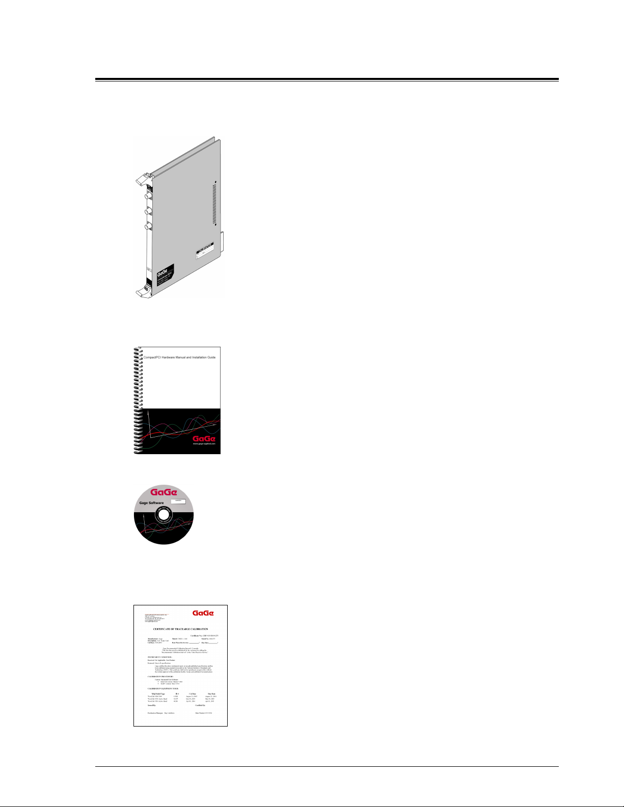
• CompuScope 85GC card
• Standard items included with each CompuScope card
Hardware manual, including Driver Installation Guide
Note that you will receive only one copy of the Hardware Manual per
order placed with Gage. Additional copies can be requested at order
time.
The Hardware Manual is also available in PDF format on the Gage
Software Disk or you can download card-specific manuals from Gage’s
Web site (www.gage-applied.com).
Gage Software Disk (with GageScope Software)
The Gage Software Disk, included on the inside-front cover of the
Hardware Manual and Installation Guide, contains all of the software
drivers you need to operate your Gage hardware. The CD also contains
all of the installers for the application packages provided by Gage,
CompuScope Certificate of NIST Traceable Calibration
including Lite, Standard and Professional editions of GageScope.
Note that some packages will only be available if you have purchased
the software and have a key provided by Gage.
Each CompuScope card is shipped with a Certificate of NIST Traceable
Calibration. NIST is the National Institute to Standards and
Technologies - the US organization that is responsible for the
definitions and measurement of metrology standards.
Prior to shipment, Gage runs each CompuScope card through a battery
of over 1000 automated performance verification tests using a NIST
traceable calibration source. The tested CompuScope is then
considered a NIST traceable calibration instrument for a period of one
year – the calibration interval that is generally accepted by the Test and
Measurement industry.
CompuScope 85GC 71

Warranty card
• You may also receive a number of optional items, if purchased:
®
GageScope
software and
Standard or Professional edition
Software Development Kits (SDKs)
& applicable manual(s)
Software Key envelope
Carefully inspect these articles before proceeding further. If you find any damage caused by transportation,
please report it to the organization from which you purchased the CompuScope card.
72 CompuScope 85GC

CompuScope 85GC compliance statement
Category Standards or description
EC Declaration of
Conformity – EMC
Australia / New Zealand
Declaration of
Conformity - EMC
Meets intent of Directive 89/336/EEC for Electromagnetic Compatibility.
Compliance was demonstrated to the following specifications as listed in the
Official Journal of the European Communities:
EN 61326 EMC requirements for Class A electrical equipment for
measurement, control and laboratory use.
1, 2, 3
IEC61000-4-2 Electrostatic Discharge (Performance criterion B)
IEC61000-4-3 RF Electromagnetic Field (Performance criterion A)
IEC61000-4-4 Electrical Fast Transient/Burst Immunity
(Performance criterion B)
IEC61000-4-5 Power Line Surge Immunity
(Performance criterion B)
IEC61000-4-6 Conducted RF Immunity (Performance criterion A)
IEC61000-4-11 Voltage Dips and Interruptions Immunity
(Performance criterion B)
EN 61000-3-2 AC Power Line Harmonic Emissions
Complies with EMC provision of Radio communications Act per the following
standard(s):
AS/NZS 2064.1/2 Industrial, Scientific and Medical Equipment: 1992
1, 2, 3
1. High-quality shielded cables must be used to ensure compliance to the above listed standards
2. Compliance demonstrated on a single card configuration
3. On the host PC used by the customer, all unused back panel slots must be covered with EMI
blocking plates
CompuScope 85GC 73

CompuScope 85GC product introduction
CompuScope 85GC is the world’s fastest CompactPCITM waveform digitizer, capable of sampling two
simultaneous input channels at rates as fast as 5 GS/s with 8 bit vertical resolution.
Recognizing that until very recently, almost all multi-MegaHertz data acquisition was done using Digital Storage
Oscilloscopes under GPIB control, Gage has ported all the features of these DSOs onto the CompuScope card.
This means that you do not have to rethink the solution in terms of a completely unknown data acquisition card.
You can simply develop the data acquisition system as if an oscilloscope were being used, but instead use a
CompuScope card to take advantage of its attractive price and performance.
Of course, CompuScope cards are much more than just another DSO under GPIB control:
• Data transfer rates from CompuScope memory to PC memory or extended memory run at least 100 times
faster than a GPIB-DSO combination
• CompuScope cards are easier to program, as Software Development Kits (SDKs) are available for C/C++,
MATLAB, LabVIEW and LabWindows/CVI.
• In case you do not want to program the CompuScope 85G, you can use the powerful GageScope
oscilloscope software to acquire, analyze and archive signals.
TM
• CompuScope cards are installed inside the CompactPCI
chassis, so there is no external box such as a
DSO.
®
74 CompuScope 85GC

CompuScope 85GC specifications
PLEASE CHECK THE GAGE WEBSITE FOR THE MOST UP-TO-DATE SPECIFICATIONS.
SYSTEM REQUIREMENT
CompactPCI PICMG compliant system with the required number of free 6U slots; controller or PC with 128 MB
RAM, 50 MB hard disk and SVGA video.
SIZE
6U CompactPCI
Occupies one (1) slot
POWER (IN WATTS)
Worst Case Typical
+ 5 Volts 25.0 W 22.0 W
+ 12 Volts 12.0 W 10.0 W
CHANNELS 1 & 2
Number of inputs: 2
Connector: BNC
Impedance: 1 MΩ, 15 pF or 50 Ω, software selectable
Coupling: AC or DC, software selectable
DC Coupled Bandwidth
All ranges except ±20 mV DC to 500 MHz
±20 mV DC to 300 MHz
Lower Frequency
AC coupled bandwidth: 10 Hz with 1 MΩ impedance
140 kHz with 50 Ω impedance
Input Voltage Ranges:
1 MΩ Input: ±20 mV, ±50 mV, ±100 mV, ±200 mV, ±500 mV,
±1 V, ±2 V, ±5 V, ±10 V, ±20 V
50 Ω Input: ±20 mV, ±50 mV, ±100 mV, ±200 mV, ±500 mV,
±1 V, ±2 V, ±5 V
Input Protection: Diode Clamped for 1 MΩ
Thermal cut-off for 50 Ω
Resolution: 8 bits
Sampling Rate
GS/s: 5, 2.5, 1
MS/s: 500, 250, 100, 50, 25, 10, 5, 2.5, 1
kS/s: 500, 100, 50, 10, 5, 1
Absolute Maximum Input:
1 MΩ Impedance: ±30 Volts (continuous)
50 Ω Impedance: ±5 Volts (continuous),
DC Accuracy: ±2% of full scale input,
derated at 0.025% per degree Celsius above 30 degrees Celsius
CompuScope 85GC 75

INTERNAL CLOCK
Source: Crystal oscillator
Accuracy: ± 50 ppm
DYNAMIC PARAMETERS
Measured using 100 MHz sine wave input at 5 GS/s, dual channel mode with amplitude of 95% of full scale on
the ±1V range. Typical values listed below:
SNR: 38 dB
SFDR: 47 dB
SINAD: 37 dB
THD: -42 dB
ENOB: 6.01 bits
ACQUISITION MEMORY
Data Storage: In on-board memory
Maximum On-board
Memory Size: 10,000 samples on each of the two channels
TRIGGERING
Number of Trigger Inputs: 1 per system
Source: CH 1, CH 2, EXT or Software
Type: Slope-and-level and software
TV Trigger Mode Type: NTSC and PAL
Trigger Level: Controlled by on-board DAC
Sensitivity: ± 5% of full scale (DC to 50 MHz)
± 12.5% of full scale (50 MHz to 500 MHz)
This number specifies the minimum required signal amplitude to cause a trigger to
occur. Smaller signals are rejected as noise.
Level Accuracy: ± 5% of full scale
Slope: Positive or Negative
Pre-Trigger: From zero to almost 100% of record length. All captured data that is not part of
post-trigger depth is pre-trigger data.
Post-Trigger Depth: 500 points minimum.
Can be defined with 100 point resolution
EXTERNAL TRIGGER
Impedance: 1 MΩ, 20 pF
Amplitude: Absolute Max ±15 Volts
Voltage Range: ±800 mV and ±8 V
Coupling: AC or DC
Bandwidth: 300 MHz
Connector: BNC
MULTI-CARD SYSTEMS
Operating Mode: Multiple/Independent
Max. number of cards: 8
76 CompuScope 85GC

OPERATING SYSTEMS SUPPORTED
• Windows 98/ME/NT*/2000/XP CompuScope Driver version 3.60.22
* Version 4, SP3 or higher
APPLICATION SOFTWARE
GageScope®: Windows-based software for programming-free operation
LITE Edition: Included with purchase, provides basic functionality
Standard Edition: Provides limited functionality of advanced analysis tools, except for Extended Math
Professional Edition: Provides full functionality of all advanced analysis tools
SOFTWARE DEVELOPMENT KITS (SDK)
• CompuScope SDK for C/C++
For Windows 98/ME/NT/2000/XP
• CompuScope SDK for MATLAB
For Windows 98/ME/NT/2000/XP
• CompuScope SDK for LabVIEW
For Windows 98/ME/NT/2000/XP
• CompuScope SDK for LabWindows/CVI
For Windows 98/ME/NT/2000/XP
WARRANTY
One year parts and labor
ALL SPECIFICATIONS SUBJECT TO CHANGE WITHOUT NOTICE
CompuScope 85GC 77

CompuScope 85GC ordering information
Hardware and Upgrades
Product Order No.
CompuScope 85GC 785-001-002
GageScope Software
Product Order No.
GageScope Lite Edition Included
GageScope Standard Edition
– purchased with CompuScope hardware
GageScope Standard Edition
– purchased independently
GageScope Professional Edition
– purchased with CompuScope hardware
GageScope Professional Edition
– purchased independently
300-100-351
300-100-352
300-100-354
300-100-355
Software Development Kits (SDKs)
Product Order No.
Gage SDK Pack on CD
(No Hardcopy of Manuals included)
Gage SDK Pack on CD
(Hardcopy of Manuals included)
CompuScope SDK for C/C++ 200-200-101
CompuScope SDK for MATLAB 200-200-102
CompuScope SDK for LabVIEW 200-200-103
CompuScope SDK for LabWindows/CVI 200-300-100
200-113-000
200-113-002
78 CompuScope 85GC

CompuScope 85GC simplified block diagram
Figure 52: CS85G simplified block diagram
CompuScope 85GC 79

CompuScope 85GC: identifying your CompuScope card(s)
Your CompuScope 85GC card is composed of the CS85GC base board and the CS85GC analog board.
You will find your CompuScope 85GC card type and version as shown in Figure 53: CS85GC labels, card type
& hardware version number. Figure 53 also shows the location of the Calibration label.
The Calibration label lists your CompuScope card’s serial numbers. You should record these serial numbers for
future reference on the technical support form found at the front of this guide.
Figure 53: CS85GC labels, card type & hardware version number
80 CompuScope 85GC

CompuScope 85GC connectors and headers
CompuScope cards connect to the outside world through connectors, both analog (BNC) and digital
(CompactPCI Bus). This section describes these connectors for the CS85GC card.
The connectors and headers on the CS85GC card are shown below:
Figure 54: Connectors on CS85GC
• CH 1 BNC connector is the single-ended input of channel 1 that is used to input an analog signal that is
sampled as Channel 1.
• CH 2 BNC connector is the single-ended input of channel 2 that is used to input an analog signal that is
sampled as Channel 2.
• External Trigger BNC connector is used to input an analog or digital signal, which may be used as an
External Trigger. External Trigger is defined exactly as in an oscilloscope: this signal can be used to
trigger the system but cannot be viewed or digitized.
TM
• CompactPCI
that complies with all specifications of the CompactPCI
CompuScope 85GC 81
connector is located at the rear of the card. This is an industry standard connector
TM
bus.

CompuScope 85GC triggering
CompuScope 85GC features state-of-the-art triggering.
The trigger circuit is identical to that of an oscilloscope. This way, a user can easily replace the Digital
Oscilloscope in his or her application with a CompuScope 85GC. A user can select the trigger source, trigger
level and trigger slope using software commands.
The user can software-select the trigger source from any one of the following:
• Channel 1
• Channel 2
• External Trigger
• Software Trigger
The selected trigger source is then compared to a trigger level set by an on-board DAC. An on-board, highspeed comparator is used for this function, making it possible to trigger on narrow pulses or glitches that are
much shorter than the sample rate.
Each time the selected signal crosses the trigger level, the on-board triggering circuitry monitors it for the slope
selected by the user. When the appropriate slope is detected, a Trigger signal is generated.
Figure 55: Generation of a trigger signal
External Trigger amplifier
The External Trigger input also has oscilloscope-like 1 MΩ / 20 pF input impedance.
Gage’s proprietary input-protection circuitry allows the FET stage to withstand voltages as high as ±15 Volts
without causing any damage to the inputs.
Software-selectable attenuation of X1 or X5 on the External Trigger input allows input ranges of ±800 mVolt
and ±8 Volt, respectively.
TV Triggering
The CompuScope 85GC provides a TV triggering mode so that it may be triggered off of standard TV signals.
TV signal protocols supported are NTSC and PAL.
CompuScope 85GC allows triggering off of even or odd signal fields or off of any horizontal line which is
specified by a line number.
82 CompuScope 85GC

CompuScope 85GC throughput & maximum PRF
A number of applications require the CompuScope 85GC to acquire data based on a rapidly occurring trigger
signal. These high Pulse Repeat Frequency (PRF) applications include imaging, radar, ultrasound and lightning
test.
The following test results were obtained using a computer configured as follows:
• Pentium III, 850 MHz processor
• 256 MB RAM
• 20 GB disk drive
• Windows 98
• 33 MHz, 32 bit CompactPCI
• All slots support bus mastering
A C application program optimized for fast repetitive capture was used for throughput measurements.
The PRF rates shown below are for dual channel data acquisition, but data is being read out of the card from
only CH 1.
TM
bus
Figure 56: Maximum PRF vs. acquisition length
Notice that a PRF of about 100 Hz can be obtained for all possible capture depths.
CompuScope 85GC 83

Notes
84 CompuScope 85GC

What you should receive with your CompuScope 82GC
If you order an independent CompuScope 82G card, you should receive the following articles:
• One CompuScope 82GC card (of memory model type purchased – 2M, 8M or 16M)
• Standard items included with each independent CompuScope card
Hardware Manual, including Driver Installation Guide
Note that you will receive only one copy of the Hardware Manual per
order placed with Gage. Additional copies can be requested at order
time.
The Hardware Manual is also available in PDF format on the Gage
Software Disk or you can download card-specific manuals from Gage’s
Web site (www.gage-applied.com).
Gage Software Disk (with GageScope Software)
The Gage Software Disk, included on the inside-front cover of the
Hardware Manual and Installation Guide, contains all of the software
drivers you need to operate your Gage hardware. The CD also contains
all of the installers for the application packages provided by Gage,
CompuScope Certificate of NIST Traceable Calibration
including Lite, Standard and Professional editions of GageScope.
Note that some packages will only be available if you have purchased
the software and have a key provided by Gage.
Each CompuScope card is shipped with a Certificate of NIST Traceable
Calibration. NIST is the National Institute to Standards and
Technologies - the US organization that is responsible for the
definitions and measurement of metrology standards.
Prior to shipment, Gage runs each CompuScope card through a battery
of over 1000 automated performance verification tests using a NIST
traceable calibration source. The tested CompuScope is then
considered a NIST traceable calibration instrument for a period of one
year – the calibration interval that is generally accepted by the Test and
Measurement industry.
CompuScope 82GC 85

Warranty card
• You may also receive a number of optional items, if purchased:
GageScope
Standard or Professional edition
®
software and
Software Development Kits (SDKs)
& applicable manual(s)
Software Key envelope
• If you ordered a Master/Slave set, you will receive a Master/Slave Timing Module in addition to the number
of CompuScope cards in your Master/Slave system.
Carefully inspect these articles before proceeding further. If you find any damage caused by transportation,
please report it to the organization from which you purchased the CompuScope card.
86 CompuScope 82GC

CompuScope 82GC compliance statement
Category Standards or description
EC Declaration of
Conformity – EMC
Australia / New Zealand
Declaration of
Conformity - EMC
Meets intent of Directive 89/336/EEC for Electromagnetic Compatibility.
Compliance was demonstrated to the following specifications as listed in the
Official Journal of the European Communities:
EN 61326 EMC requirements for Class A electrical equipment for
measurement, control and laboratory use.
1, 2, 3
IEC61000-4-2 Electrostatic Discharge (Performance criterion B)
IEC61000-4-3 RF Electromagnetic Field (Performance criterion A)
IEC61000-4-4 Electrical Fast Transient/Burst Immunity
(Performance criterion B)
IEC61000-4-5 Power Line Surge Immunity
(Performance criterion B)
IEC61000-4-6 Conducted RF Immunity (Performance criterion A)
IEC61000-4-11 Voltage Dips and Interruptions Immunity
(Performance criterion B)
EN 61000-3-2 AC Power Line Harmonic Emissions
Complies with EMC provision of Radio communications Act per the following
standard(s):
AS/NZS 2064.1/2 Industrial, Scientific and Medical Equipment: 1992
1, 2, 3
1 Emissions which exceed the levels required by this standard may occur when this equipment is
connected to a test object.
2 High-quality shielded cables must be used to ensure compliance to the above listed standards.
3 Compliance demonstrated on a two card Master/Slave configuration (qty 2 cards maximum).
CompuScope 82GC 87

CompuScope 82GC product introduction
CompuScope 82GC is an 8 Bit, waveform digitizer card for the CompactPCITM Bus, capable of 2 GS/s sampling
on one channel and 1 GS/s sampling on two simultaneous channels.
Recognizing that until very recently, almost all multi-MegaHertz data acquisition was done using Digital Storage
Oscilloscopes under GPIB control, Gage has ported all the features of these DSOs onto the CompuScope card.
This means that you do not have to rethink the solution in terms of a completely unknown data acquisition card.
You can simply develop the data acquisition system as if an oscilloscope were being used, but instead use a
CompuScope card to take advantage of its attractive price and performance.
Of course, CompuScope cards are much more than just another DSO under GPIB control:
• CS82GC features deep acquisition memory of up to 16 MB.
• Multi-card Master/Slave systems provide scalability from 2 to 4 channels of simultaneous A/D conversion.
• Data transfer rates from CompuScope memory to PC memory or extended memory run as high as 80 MB/s
for the CS82GC as compared to a few hundred KB/s for GPIB.
• CompuScope cards are easier to program, as Software Development Kits (SDKs) are available for C/C++,
MATLAB, LabVIEW and LabWindows/CVI.
• CompuScope cards are installed inside the CompactPCI
DSO.
• The CS82GC cards have Pre-Trigger Multiple Record as a standard feature, which helps optimize the use of
the on-board memory by stacking data from successive bursts.
• You can also write software for a multi-card system in which all the cards are not in a Master/Slave
configuration. Drivers supplied by Gage support all these multi-card configurations.
• In case you do not want to program the CompuScope 82GC card(s), you can use the powerful GageScope
oscilloscope software to acquire, analyze and archive signals.
TM
chassis, so there is no external box such as a
®
Special features on the CompuScope 82GC include:
• Bus Mastering
CompuScope 82GC is fully capable of becoming a bus master in order to transfer data at the maximum rate
of 80 MB/s.
A bus Master is a card that can take control of the bus and transfer data to any PCI target device such as
system RAM without any involvement from the CPU.
• External Clocking
CompuScope 82GC comes standard with external clocking capability that allows synchronization of the
digitizers with an external reference clock.
• Trigger Output
CompuScope 82GC provides a TTL output on one of the front panel connectors. The rising edge of this
output signifies that a trigger event has been detected on the CompuScope 82GC.
• Pre-Trigger Multiple Record
Pre-Trigger Multiple Recording allows CompuScope 82G to collect pre-trigger data when the card is in
Multiple Record mode. Up to 32 K points can be captured as pre-trigger data.
88 CompuScope 82GC

CompuScope 82GC specifications
PLEASE CHECK THE GAGE WEBSITE FOR THE MOST UP-TO-DATE SPECIFICATIONS.
SYSTEM REQUIREMENT
CompactPCI PICMG compliant system with the required number of free 6U slots; controller or PC with 128 MB
RAM, 50 MB hard disk and SVGA video.
There must be at least 10 A of 5 V and 3.3 A of 3.3 V for each CS82GC card
The CompuScope 82GC must be installed in a slot that supports bus mastering to achieve stated performance.
SIZE
6U CompactPCI
Occupies one (1) slot
POWER (IN WATTS)
Worst Case Typical Power Down
+ 5 Volts 50.0 W 46.0 W 7.0 W
+ 12 Volts 5.0 W 4.0 W 4.0 W
+ 3.3 Volts 11.0 W 10.0 W 1.0 W
- 12 Volts 3.0 W 3.0 W 3.0 W
CHANNELS 1 & 2
Inputs per card: 2
†
Impedance: 1 MΩ, 25 pF or 50 Ω, software selectable
†
Coupling: AC or DC
Resolution: 8 bits
†
Typical DC Coupled Bandwidth:
50 ΩΩΩΩ
Dual Channel
50 ΩΩΩΩ
Single Channel
±100 mV N/A N/A 250 MHz 200 MHz
±200 mV 250 MHz 150 MHz 300 MHz 200 MHz
±500 mV 400 MHz 300 MHz 300 MHz 250 MHz
±1 V 400 MHz 300 MHz 300 MHz 250 MHz
±2 V 400 MHz 300 MHz 300 MHz 250 MHz
±4 V 400 MHz 300 MHz N/A N/A
±5 V N/A N/A 300 MHz 250 MHz
±10 V N/A N/A 300 MHz 250 MHz
Lower Frequency Limit
AC Coupled: 1 MΩ Input: 10 Hz
50 Ω Input: 20 kHz
†
Input Voltage Ranges:
1 MΩ: ±100 mV, ±200 mV, ±500 mV,
±1 V, ±2 V, ±5 V, ±10 V
50 Ω: ±200 mV, ±500 mV,
±1 V, ±2 V, ±4 V
1 MΩΩΩΩ
Dual Channel
1 MΩΩΩΩ
Single Channel
CompuScope 82GC 89

Absolute Maximum Amplitude:
1 MΩ: ±15 Volts (continuous)
50 Ω: ±5 Volts (continuous)
DC Accuracy relative to full scale input:
All ranges: ±2% of full scale
Sampling Rate
Single-Channel Mode (Channel 1 only)
G S/s: 2, 1
MS/s: 500, 250, 200, 100, 40, 20
Dual-Channel Mode (Channels 1 and 2 simultaneously)
GS/s: 1
MS/s: 500, 250, 125, 100, 50, 20, 10, 5, 2, 1
kS/s: 500, 200, 100
†
Input Protection
1 MΩ impedance: Diode Clamped
50 Ω impedance: No protection
Connector: BNC
†
DYNAMIC PARAMETERS
Measured using a sine wave input at 1 GS/s, dual channel mode with amplitude of 95% of full scale on the ±1 V
range with a 50 Ω input. Typical values are listed below.
10 MHz Input 100 MHz Input
SNR 45 dB 43 dB
SFDR 54 dB 50 dB
SINAD 44 dB 42 dB
THD -52 dB -48 dB
ENOB 7.2 bits 6.85 bits
ACQUISITION MEMORY
Data Storage: In on-board memory
Memory sizes: 2 M, 8M, 16M (8 bit samples)
Maximum memory depth:
Single Channel Mode: Up to full on-board memory
Dual Channel Mode: Up to half on-board memory per channel
†
TRIGGERING
Number of Trigger Inputs: 1 per system
Trigger Source: CH 1, CH 2, EXT or Software
Type: Analog triggering
Sensitivity: ± 10% of full scale
Level Accuracy: ± 5% of full scale
Slope: Positive or Negative, software selectable
Post Trigger Data: 256 (512) points minimum.
Can be defined with a 128 (256) point resolution in dual (single) channel mode
90 CompuScope 82GC

EXTERNAL TRIGGER
Impedance: 1 MΩ, 25 pF
Amplitude: Absolute Max ±15 V
Voltage Range: ±1 V and ±5 V
Bandwidth: 300 MHz
Coupling: AC or DC
Connector: BNC
TRIGGER OUTPUT
Signal Type: TTL
Active Edge: Rising (low-to-high)
Synchronization: Synchronized to on-board system clock
INTERNAL CLOCK
Source: 1 GHz SAW oscillator
Accuracy: ± 200 ppm
EXTERNAL CLOCK
Maximum Frequency: 1 GHz
Minimum Frequency: 10 MHz
Signal Type: Sine wave
Connector: SMA
Signal Level: MIN 225 mV RMS
MAX 500 mV RMS
Impedance: 50 Ω
Sampling Edge:
Single: Rising and Falling
Dual: Rising
Coupling: AC
Duty Cycle: 50% ±5% Single/Dual
MULTIPLE RECORD
Pre-trigger Data: Up to 32K points
Record Length: 256 (512) points minimum.
Can be defined with a 128 (256) point resolution in dual (single) channel mode
Max. number of Triggers: 21,845 with 16M model
Re-arm time: 152 (304) sample clock cycles in dual (single) channel mode
MULTI-CARD SYSTEMS
Operating modes: Master/Slave or Multiple Independent
Number of Cards
Master/Slave: 2 cards
Multiple/Ind.: Limited by backplane
Maximum Number of Channels in Master/Slave Mode:
4 at 1 GS/s
2 at 2 GS/s
CompuScope 82GC 91

MASTER/SLAVE SYSTEM TRIGGERING
Number of Trigger Inputs: 1 per system
Trigger Source: CH 1, CH 2, EXT or Software (Master card only)
Sensitivity: ± 10% of full scale
Level Accuracy: ± 5% of full scale
Slope: Positive or Negative, software selectable
OPERATING SYSTEMS SUPPORTED
• Windows 98/ME/NT* CompuScope Driver version
* Version 4, SP3 or higher
• Windows 2000**/XP CompuScope Driver version 3.82.xx
** SP1 or higher
†
3.60.22
APPLICATION SOFTWARE
GageScope®: Windows-based software for programming-free operation
LITE Edition: Included with purchase, provides basic functionality
Standard Edition: Provides limited functionality of advanced analysis tools, except for Extended Math
Professional Edition: Provides full functionality of all advanced analysis tools
SOFTWARE DEVELOPMENT KITS (SDK)
• CompuScope SDK for C/C++
For Windows 98/ME/NT/2000/XP
• CompuScope SDK for MATLAB
For Windows 98/ME/NT/2000/XP
• CompuScope SDK for LabVIEW
For Windows 98/ME/NT/2000/XP
• CompuScope SDK for LabWindows/CVI
For Windows 98/ME/NT/2000/XP
ENVIRONMENTAL
Operating Temperature: 5 degree Celsius to 40 degree Celsius
Relative Humidity: Less than 80%, non-condensing
Maximum Altitude: 2,000 meters
ELECTROMAGNETIC COMPATIBILITY
The following CS82GC configurations have been tested for CE Compliance:
1 Card: CE Compliant
2 Card M/S Set: CE Compliant
WARRANTY
One year parts and labor
ALL SPECIFICATIONS SUBJECT TO CHANGE WITHOUT NOTICE
†
These specs differ on the CompuScope 82GC – 1GHz Bandwidth version.
Please refer to the section: CompuScope 82GC - 1 GHz Bandwidth version on page 104 for specs on this
model.
92 CompuScope 82GC

CompuScope 82GC ordering information
Hardware and upgrades
Product Order No.
CompuScope 82GC - 2M 782-001-001
CompuScope 82GC - 8M 782-001-002
CompuScope 82GC - 16M 782-001-003
CS82GC: Memory Upgrade Charge 782-181-004
CS82GC: Master/Slave Modification Charge 782-181-005
CS82GC: Upgrade to 1 GHz Bandwidth 782-181-006
CS82GC-2M: 2 Card Master/Slave Set 782-001-010
CS82GC-8M: 2 Card Master/Slave Set 782-001-020
CS82GC-16M: 2 Card Master/Slave Set 782-001-030
CS82GC-1GHz - 2M 782-001-202
CS82GC-1GHz - 8M 782-001-203
CS82GC-1GHz - 16M 782-001-204
CS82GC-1GHz - 2M with Internal Trigger 782-001-205
CS82GC-1GHz - 8M with Internal Trigger 782-001-206
CS82GC-1GHz - 16M with Internal Trigger 782-001-207
CS82GC-1GHz - 2M: 2 Card Master/Slave Set 782-001-110
CS82GC-1GHz - 8M: 2 Card Master/Slave Set 782-001-120
CS82GC-1GHz - 16M: 2 Card Master/Slave Set 782-001-130
CS82GC-1GHz - 2M: 2 Card Master/Slave Set
with Internal Trigger
CS82GC-1GHz - 8M: 2 Card Master/Slave Set
with Internal Trigger
CS82GC-1GHz - 16M: 2 Card Master/Slave Set
with Internal Trigger
782-001-110
782-001-120
782-001-130
GageScope Software
Product Order No.
GageScope Lite Edition Included
GageScope Standard Edition
– purchased with CompuScope hardware
GageScope Standard Edition
– purchased independently
GageScope Professional Edition
– purchased with CompuScope hardware
GageScope Professional Edition
– purchased independently
CompuScope 82GC 93
300-100-351
300-100-352
300-100-354
300-100-355
Software Development Kits (SDKs)
Product Order No.
Gage SDK Pack on CD
(No Hardcopy of Manuals included)
Gage SDK Pack on CD
(Hardcopy of Manuals included)
CompuScope SDK for C/C++ 200-200-101
CompuScope SDK for MATLAB 200-200-102
CompuScope SDK for LabVIEW 200-200-103
CompuScope SDK for LabWindows/CVI 200-300-100
200-113-000
200-113-002
94 CompuScope 82GC
 Loading...