

GAF Master Flow PG2, Master Flow PG3, Master Flow EGV6, Master Flow EGV5 Installation Instructions Manual

Master Flow®
Power Attic Vent – Gable Mount
Installation Instructions
V971382
Updated: 6/15
www.gaf.com
POWER ATTIC VENT
Gable Mount
Installation Instructions
For Gable-Mount Models: PG2, PG3,
EGV5 & EGV6
Always read and observe safety considerations and installation instructions.
Safety Considerations & Warnings
1. Use this unit only in the manner intended by GAF.
If you have any installation questions, please contact
Master Flow® Technical Services at 1-800-211-9612.
2. For general ventilating use only. This ventilator has an
unguarded impeller. Do NOT use in locations readily
accessible to people or animals.
3. Do NOT use to exhaust hazardous material, dust,
or combustible vapors.
4. During installation, always wear appropriate safety
glasses, gloves, hard hats, restraints, and other safety
equipment to avoid injury. Warning: Always wear
durable work gloves while handling the unit.
5. Observe all applicable building and electrical codes.
6. Installation work and electrical wiring should be done by
a qualified person in accordance with all building codes
and the National Electrical Code (U.S. only), including
codes for fire ratings. Contact a qualified electrician if
you are not comfortable or familiar with electrical codes
and/or installations.
7. The ventilator should be connected to a 120 volt, 60 Hz
grounded circuit only with minimum 14-gauge wiring
that has at least 3 amperes of available capacity. If you
cannot confirm there is sufficient electrical capacity on
an existing circuit, install a separate dedicated circuit.
Do NOT use an extension cord to operate.
8. Inspect for hidden utilities before cutting or drilling.
Do NOT damage electrical wiring or other hidden
utilities when cutting or drilling.
9. Make sure the fan blade is on tight and ensure the set
screw is securely tightened.
10. Ducted fans must always be vented to the outdoors.
11. FOR HOMES WITH A GAS OR OIL FURNACE OR
APPLIANCE LOCATED IN THE SAME SPACE:
The ventilator MUST be wired with a switch or other
interlocking device to prevent the furnace and ventilator
from operating at the same time during the heating
cycle. The switch or other interlocking device MUST
disconnect the vent unit from the electrical circuit power.
GAF recommends that the switch (not included) be
installed by a qualified person in accordance with all
applicable building codes and standards.
Tools Required
• 3/8” or Adjustable Wrench
• #2 Phillips Screwdriver
• Saw (if installation requires
additional wood supports)
• Safety Eyewear
• Fall Restraint Equipment
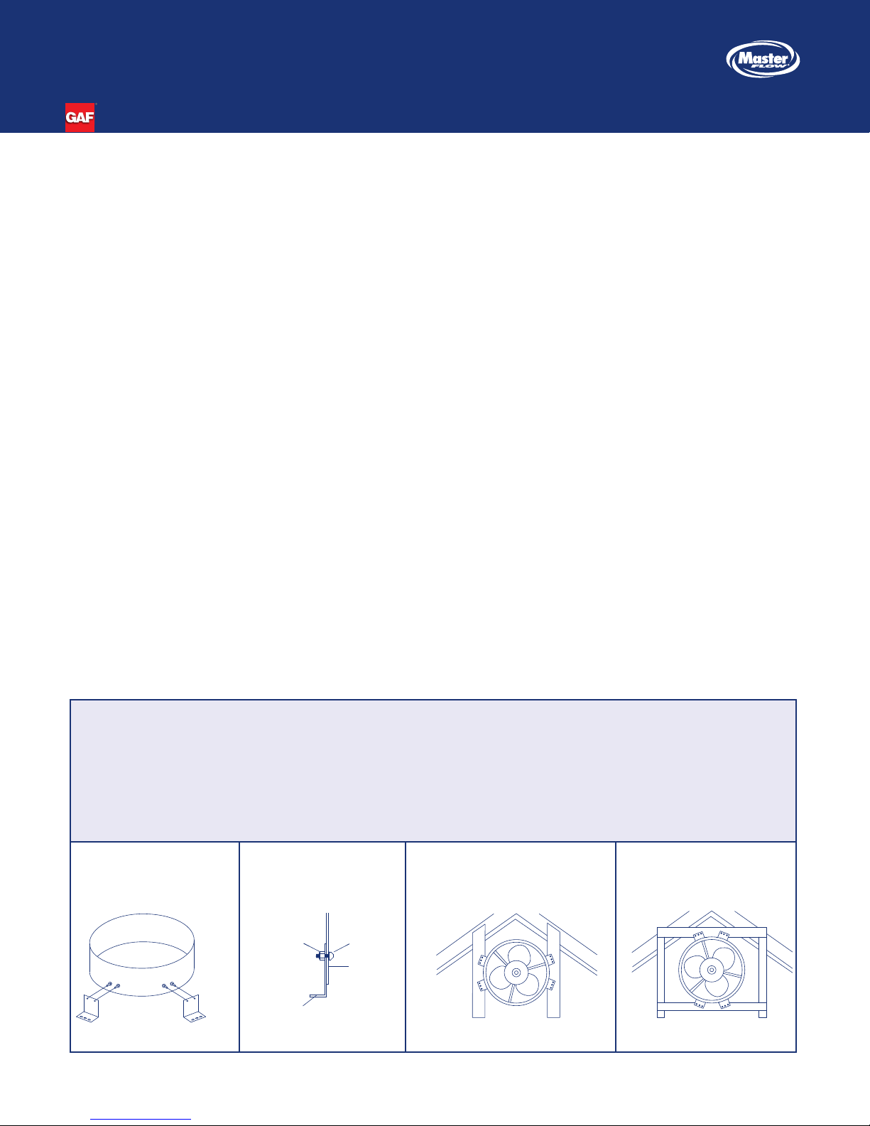
Figure 1a Figure 1b
Nut
Mounting
Brackets
• Hard Hat and other
Safety Equipment
• Utility Knife
• Gloves
• Ladder
• Claw Hammer
Bolt
Shroud
Figure 2a
• Pencil or Marker
• Tape Measure
• 1/2” Trade Size Cable
Clamp Connector
• Type NM Electrical Cable
• Wire Nuts
Figure 2b
Figure 2b
V971382©2015 GAF 6/15 1 Campus Drive, Parsippany, NJ 07054
Installation Instructions
Note: See Figures on previous page.
1. Ensure Proper Intake Ventilation... Always
ensure there is proper intake ventilation at the soffit, undereave, and fascia areas of the roof. This is
required for a balanced ventilation system and to help
avoid premature ventilator motor failure. Use the chart
located on the outside of the package to ensure the
minimum recommended intake ventilation is installed
on the home. Always consult local building codes for
ventilation requirements.
2. Determine Position... Place Power Gable Vent
behind an existing gable wall louver or install a
Master Flow® SGM20 Automatic Gable Louver
(not included). The fan should be approximately
3" (76 mm) to 4" (102 mm) away from the
exterior louver.
3. Attach Mounting Brackets To Unit… Carefully
remove unit and mounting accessories kit from the carton. The fan mounting kit includes (8) bolts, (8) Nylok™
nuts, and (4) mounting brackets. Take the mounting
brackets (long side) and align with the two holes on
the shroud. With holes aligned, take two bolts with the
head on the inside of the shroud and push through
each hole. Take the Nylok™ nuts and fasten to each
bolt. Repeat this process until all four mounting brackets are firmly fastened to shroud (Figures 1a & 1b).
4. Mount The Unit... Place mounting brackets so end
is flush with the stud. For studs 16" (40.6 cm) on center, mounting brackets are predrilled to this size. Screw
or nail unit to framing through pre-punched holes in
For Gable-Mount Models: PG2, PG3,
EGV5 & EGV6
mounting brackets (Figure 2a). For studs over 16" (406
mm) on center, install two nominal 2" x 4" (50 mm x
100 mm) wood supports, 14" (35.6 cm) apart. Mount
the unit to the two nominal 2" x 4" (50 mm x 100 mm)
wood supports through the pre-punched holes in the
mounting brackets (Figure 2b).
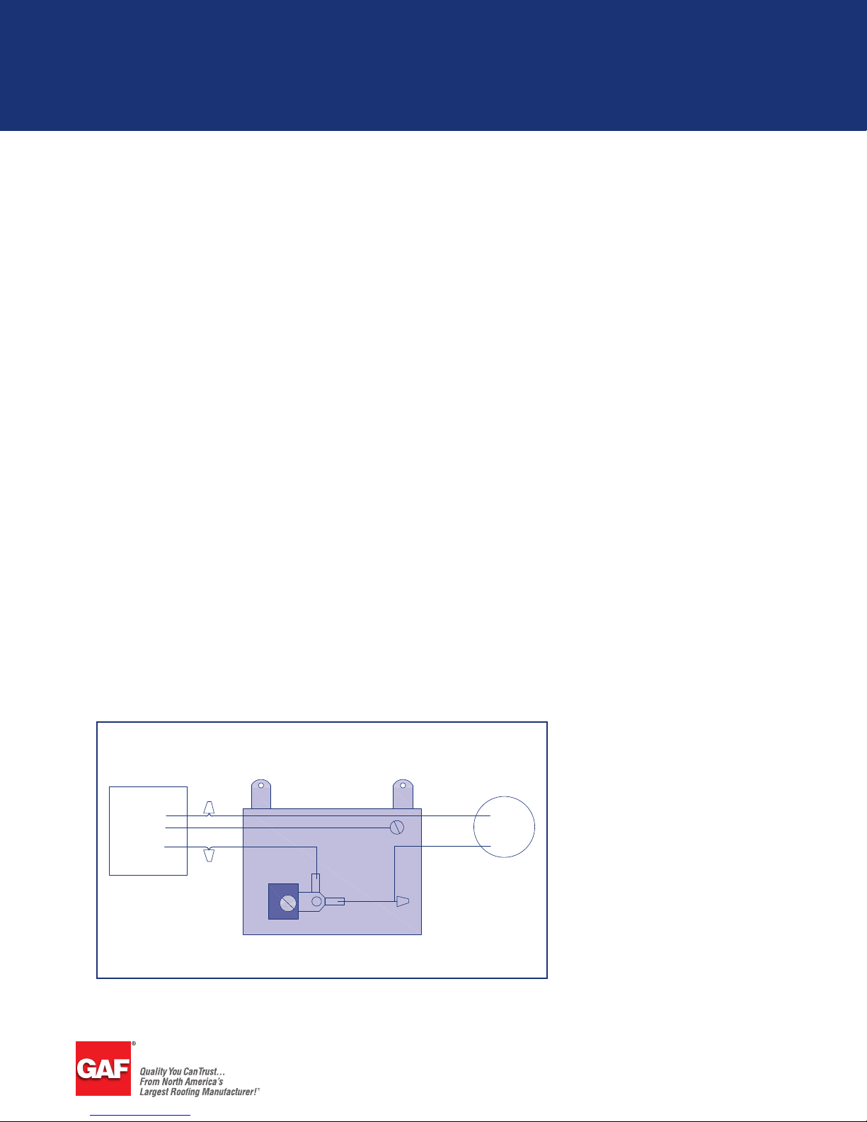
5. Wiring... Always disconnect power supply before
wiring the ventilator into an existing circuit. Remove
the thermostat cover and mount the thermostat box
to the edge of an adjacent rafter or stud using the
pre-punched holes. Make sure the thermostat element
opening on the back of the box isn’t covered. Each
ventilator must have its own thermostat. Leave the
flexible conduit with some slack and begin wiring
the thermostat as shown (Figure 3). The included
thermostat is adjustable from 60°F (15.5°C) to 120°F
(48.8°C). The factory/recommended setting for
efficient operation is 105°F (40.5°C).
Note: In the unlikely event that accessories or parts
are missing or this product does not operate correctly,
please contact Master Flow® Technical Services at
1-800-211-9612. Do NOT return this ventilator to
retailers or distributors.
Figure 3
POWER SOURCE
WHITE
GREEN
BLACK
BLACK
GREEN
WHITE
MOTOR
BLACK
BLACK
gaf.com
 Loading...