

Page 1
P a g e | 1
GAF Solar Energy System ©2019 GAF All Rights Reserved. Version 3.1 08/2019
FF
Page 2

P a g e | 2
1 Contents
SECTION 1 — INTRODUCTION ................................................................................................................. 4
Abbreviations .................................................................................................................................. 4
Symbol List ..................................................................................................................................... 4
Definitions ....................................................................................................................................... 5
General Safety Precautions ............................................................................................................. 6
Electrical Safety Precautions ........................................................................................................... 7
SECTION 2 - GAF SOLAR ENERGY SYSTEM OVERVIEW .............................................................................. 9
Main Components of the GAF Solar Energy System ..................................................................... 9
GAF Solar System Components .................................................................................................... 10
Solar Array Configurations ........................................................................................................... 13
SECTION 3 — GAF SOLAR ENERGY SYSTEM CONSIDERATIONS AND REQUIREMENTS .............................. 14
Design Considerations ................................................................................................................... 14
Installation Requirements .............................................................................................................. 16
Grounding ...................................................................................................................................... 17
Recommended Tools ..................................................................................................................... 21
Prior to Installation ........................................................................................................................ 22
SECTION 4 — GAF SOLAR ENERGY SYSTEM INSTALLATION .................................................................... 23
Step 1: Prep the Roof ..................................................................................................................... 24
Step 2: Build the Starter Bars and the Solar Module Assemblies ................................................. 28
Step 3: Install the Starter Bar ........................................................................................................ 34
Step 4: Install the First Row of Solar Module Assemblies ........................................................... 36
Step 5: Install the Remaining Rows of Solar Module Assemblies ................................................ 41
Step 6: Install Side Flashing .......................................................................................................... 42
Step 7: Install Top Flashing ........................................................................................................... 44
Step 8: Install Top Flashing Underlayment and Complete Shingles ............................................. 49
Completed GAF Solar Energy System .......................................................................................... 51
SECTION 5 — WIRE MANAGEMENT ...................................................................................................... 52
DC Optimizer ................................................................................................................................ 52
AC Microinverter .......................................................................................................................... 52
SECTION 6 — GAF SOLAR ENERGY SYSTEM MANINENANCE ................................................................... 54
SECTION 7 — APPENDIX ....................................................................................................................... 55
GAF Solar Module Technical Data ............................................................................................... 55
Page 3

P a g e | 3
GAF Solar Energy System Codes and Standards .......................................................................... 58
Alternate Solar System Configurations ......................................................................................... 59
Version Control .................................................................................................................................... 63
Page 4
P a g e | 4
SECTION 1 — INTRODUCTION
The GAF Solar Energy System is designed by GAF, North America’s largest roofing manufacturer. The sleek,
black, low-profile design delivers performance and curb appeal at an affordable price. The GAF Solar Energy
System was developed with roofing best practices, simplicity of installation, performance, safety, and aesthetics
in mind. Its deck-mounting technology coupled with GAF underlayment offers fast installation with highperformance water shedding and a Class A fire rating. Module Level Power Electronics (either AC or DC) is easily
integrated in the field.
This Manual contains safety, installation, and troubleshooting instructions for the GAF Solar Energy System.
READ THESE INSTRUCTIONS ENTIRELY AND THOROUGHLY TO HELP ENSURE A PROBLEMFREE INSTALLATION.
Save this Manual and keep it in a readily accessible location for future reference. As part of its continuing
efforts to improve the performance of its products, GAF periodically makes changes to its products and
application specifications. GAF reserves the right to change or modify, at its discretion, any of the information,
requirements, specifications, or policies contained herein. Please be sure to check gaf.com/solar for the most
up-to-date version of this Manual or any technical bulletins for this product.
Abbreviations
AC Alternating Current
AHJ Authority Having Jurisdiction
ANSI American National Standards Institute
ASTM American Society for Testing and Materials
AWG American Wire Gage
DC Direct Current
OCPD Overcurrent Protection Device
OSB Oriented Strand Board
OSHA Occupational Safety and Health Administration
MLPE Module Level Power Electronics
NEC National Electrical Code
NFPA National Fire Protection Association
MC Multi-Contact
PPE Personal Protective Equipment
PV Photovoltaic
UL Underwriters Laboratories
Symbol List
CAUTION: Use caution and fully understand the instructions before proceeding.
DANGER: Indicates a hazardous situation. Failure to follow these instructions could lead to serious injury
or death.
NOTE: Follow these instructions closely for optimal system operations and best installation practices.
MOVE: Denotes direction of movement.
Page 5
P a g e | 5
Back
Adjustable feet
Bracket
Definitions
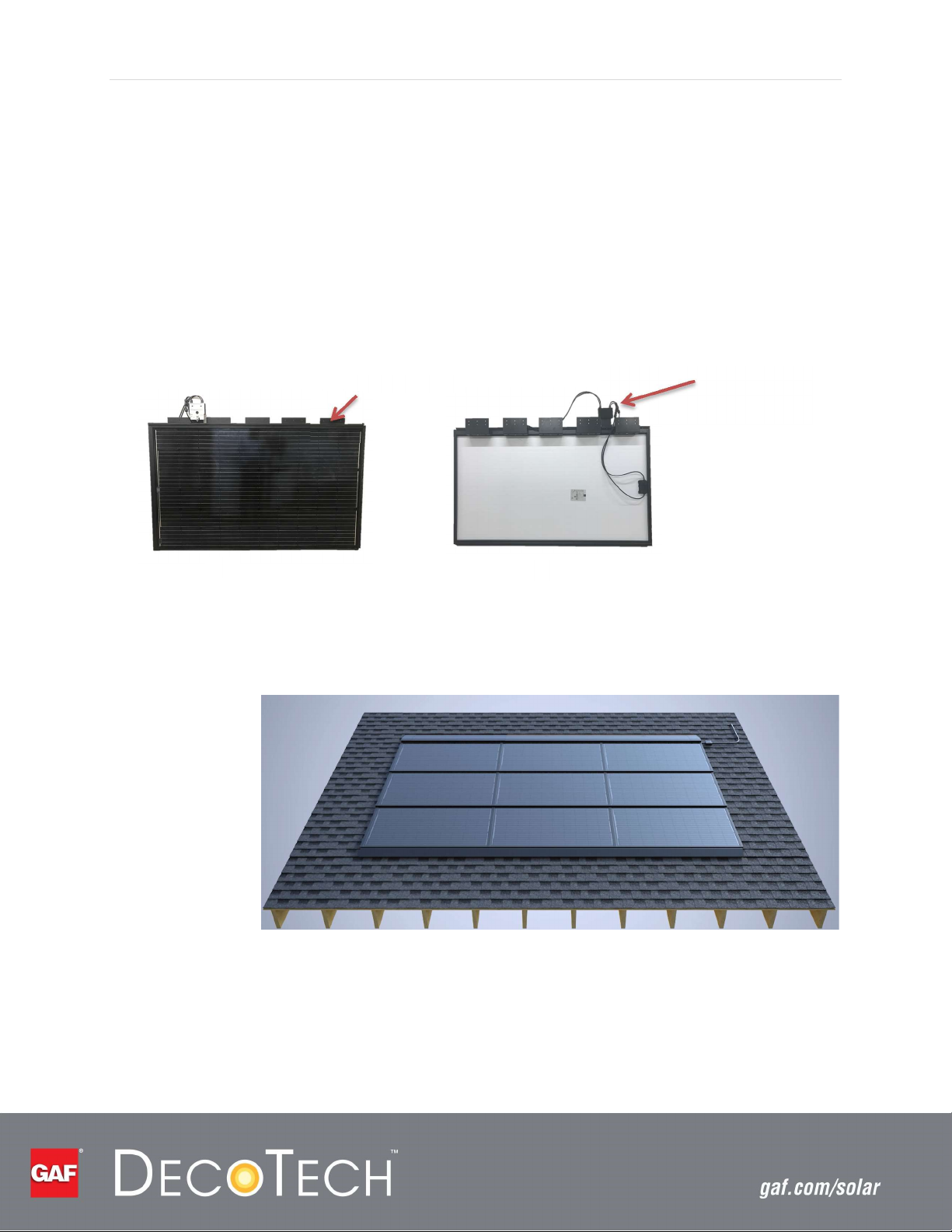
GAF Solar Module Assembly – the GAF solar module combined with:
Roof attachments (adjustable feet)
MLPE bracket
MLPE (either a DC optimizer or an AC Microinverter)
Wire ties
Grounding lug
The Module Assembly is built in the field with the provided hardware. Detailed instructions are in Section
4.
MLPE mounted
on the MLPE
Front
Figure 1 GAF Solar Module Assembly
GAF Solar Energy System — The combination of GAF underlayment, Module Assemblies, Starter Bars, and
Flashing make up the GAF Solar Energy System as shown in Figure 2.
Figure 2 GAF Solar Energy System
Page 6
P a g e | 6
General Safety Precautions
Must be installed by a qualified person… The GAF Solar Energy System must be installed by a PROPERLY
TRAINED and QUALIFIED INSTALLER. It is the responsibility of every installer to know and follow local
code requirements.
Follow OSHA… GAF recommends compliance with OSHA guidelines for Residential Fall Protection.
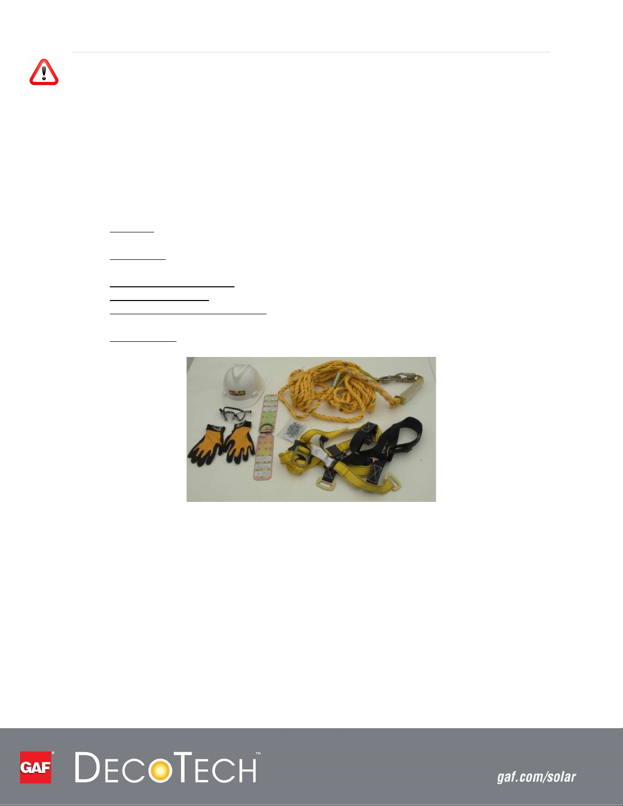
Wear Personal Protective Equipment (PPE)… Use proper PPE (Figure 3) and follow safety policies and
procedures. Proper PPE when dealing with rooftop solar systems includes, but is not limited to, the
following:
o Hard hats… For falling objects, as well as risk of contact with energized conductors. An ANSI Z89
Class A helmet will satisfy this OSHA requirement.
o Work gloves… For slip, abrasion, and thermal resistance. Solar modules tend to get very hot when
exposed directly to the sun.
o Electrically insulated gloves… When working on energized circuits.
o Appropriate footwear… Footwear with extra traction and/or heat-resistant soles.
o Personal fall arrest system (PFAS)… Consists of an OSHA-approved anchor point, a full-body
harness approved for electrical workers, rope or cable, and specific connecting hardware.
o Eye protection… For site-specific hazards.
Figure 3 personal Protective Equipment
Work only in dry conditions… Use dry equipment and dry tools. Protect all electrical equipment against
weather elements.
Eliminate trip and fall hazards… Keep work areas on the roof and ground staging areas organized and
clean.
Beware of “in-between” roof slopes… A “walkable” roof may not be walkable once the shingles are
stripped off. A slope of 6:12 and higher generally becomes unsafe to walk on after being stripped.
No stacking of Module Assemblies… Do not stack or store Module Assemblies on the roof. For general
safety of roofing materials, use roof jacks, toe boards, or storage platforms secured to the underlying roof
deck to prevent slippage of stored roofing materials.
Page 7
P a g e | 7
Inspect for damage… Do not use GAF Solar Energy System components if there are visible signs of damage
from transport or handling.
Handling the Module Assembly… Always have two people carry the product by its frame. Do not support
the solar modules on your head as a hard hat may damage the PV back sheet.
Working Safely with PV systems… Be aware of the hazards at the jobsite as well as the hazards of working
on PV systems. Be alert at all times. Never work alone on PV systems. Always have at least two people
installing solar systems on the roof.
Electrical Safety Precautions
Must be competent with electrical safety work practices… The GAF Solar Energy System is an electric-
powered generation system. The installer must be qualified according to state and local requirements.
De-energize… All work must be performed on DC or AC circuits only after the circuits have been de-
energized.
Use proper wire management techniques... Ensure that none of the AC or DC wires are pinched or
damaged during installation. Secure all loose cables with wire ties to the GAF Solar Module Assembly. Do
not exceed the minimum bend radius of the cables.
Do not modify factory-applied connectors, terminals, or jumper cables… Do not customize or modify the
provided DC or AC cables or connectors in the field.
Do not repair… The GAF Solar Energy System does not contain any user-serviceable parts. Replacement
products should be obtained through GAF. Tampering with the GAF Solar Energy System will void the
warranty.
Thermal and voltage hazard… Certain parts of the GAF Solar Energy System may become extremely hot
due to continued exposure to the sun. It should be installed in a location where it is protected against
casual contact. It may also represent an electrical hazard while servicing the system immediately following
shutdown.
Follow codes… Perform all electrical installations in accordance with all local codes and the NEC (National
Electrical Code) ANSI/NFPA 70 for U.S. installations.
Re-inspection… Regularly re-inspect the solar system to ensure that all fasteners are securely tightened
and corrosion free; that wiring is securely connected and free of corrosion; and that cables are free of
damage. This is important especially after storms and in areas prone to hail and high winds. Any damaged
parts should be replaced immediately.
Be aware of ground faults… Functionally grounded conductors may become ungrounded and energized
when a ground fault is indicated, resulting in risk of electric shock. Prior to touching any part of the
Page 8

P a g e | 8
product, use care to ensure surfaces and equipment are at touch-safe temperatures and voltage
potentials (by testing with a multimeter) before proceeding. Anytime the MLPE has been disconnected
from the power network, use extreme caution as some components can retain a charge sufficient to
create a shock hazard.
Licensed Electrician… Installing AC or DC circuits, switches, tie-in to the PV point of connection, OCPDs,
and initial startup of the PV system must be performed by a licensed electrician. Make all electrical
connections (e.g., conductor termination, fuses, potential earth connection, etc.) in accordance with the
electrical standards prescribed by the applicable NEC wiring methods and/or by other local regulations
and codes.
Page 9
SECTION 2 - GAF SOLAR ENERGY SYSTEM OVERVIEW
Main Components of the GAF Solar Energy System
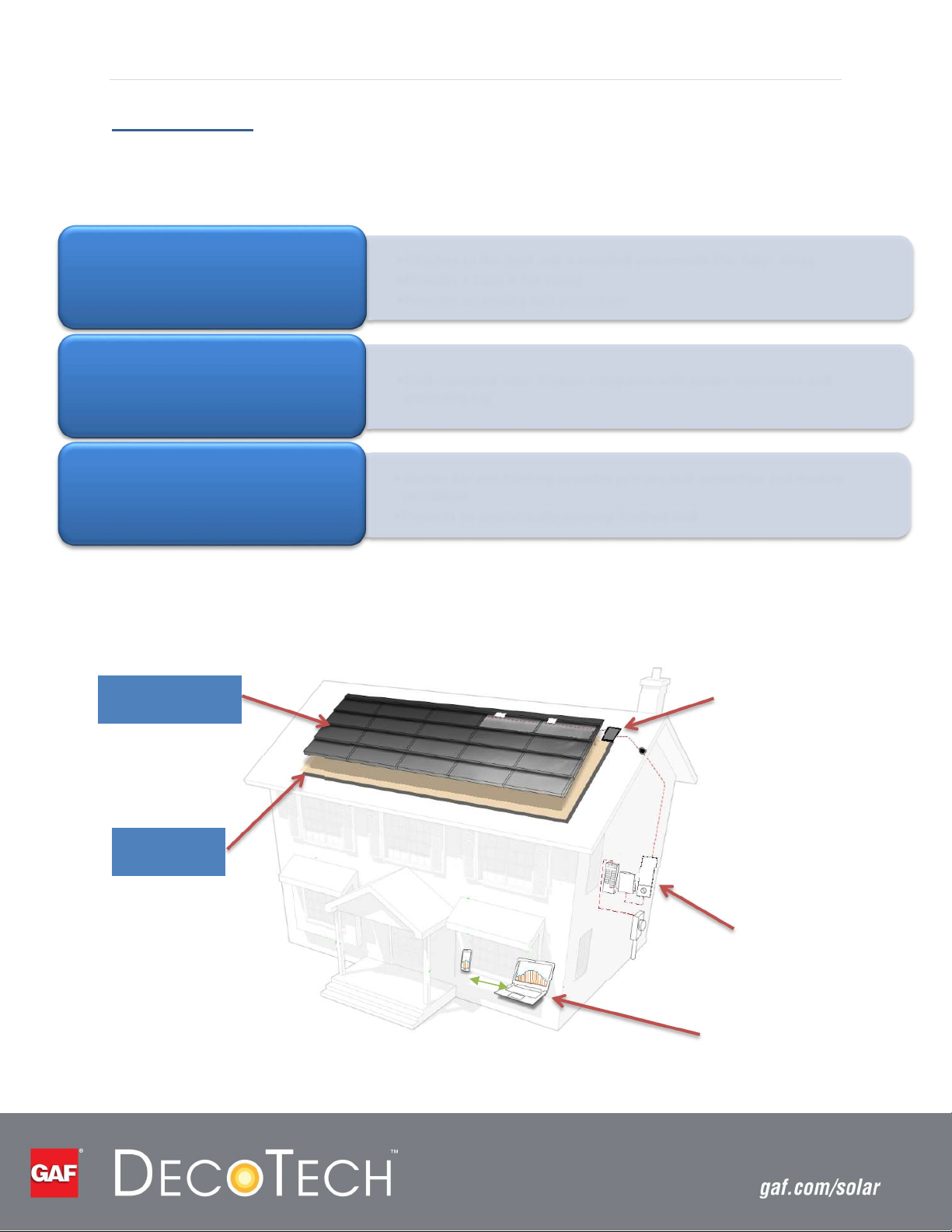
The three main components of the GAF Solar Energy System are:
•Attaches to the deck and is installed underneath the Solar Array
GAF Underlayment System
•Provides a Class A fire rating
•Provides secondary leak protection
P a g e | 9
Module Assembly
Flashing
•Deck-mounted Solar Module integrated with power electronics and
grounding lug
• Starter Bar and Flashing provides primary leak protection and module
ventilation
•Presents an aesthetically-pleasing finished look
The Balance Of System components that make up the remainder of the solar installation are outside the
scope of this manual. Typical components are: roof-top junction box, conduit and cables, disconnect
switch, meter, monitoring system, and inverter. See the Project Installation Drawings for more
information.
GAF Array with
Flashing
Junction Box and
Wiring
GAF
Underlayment
Figure 4 Main Components of Solar Installation
Inverter,
Disconnects, and
Metering
Monitoring
Page 10
Assembly
GAF Solar System Components
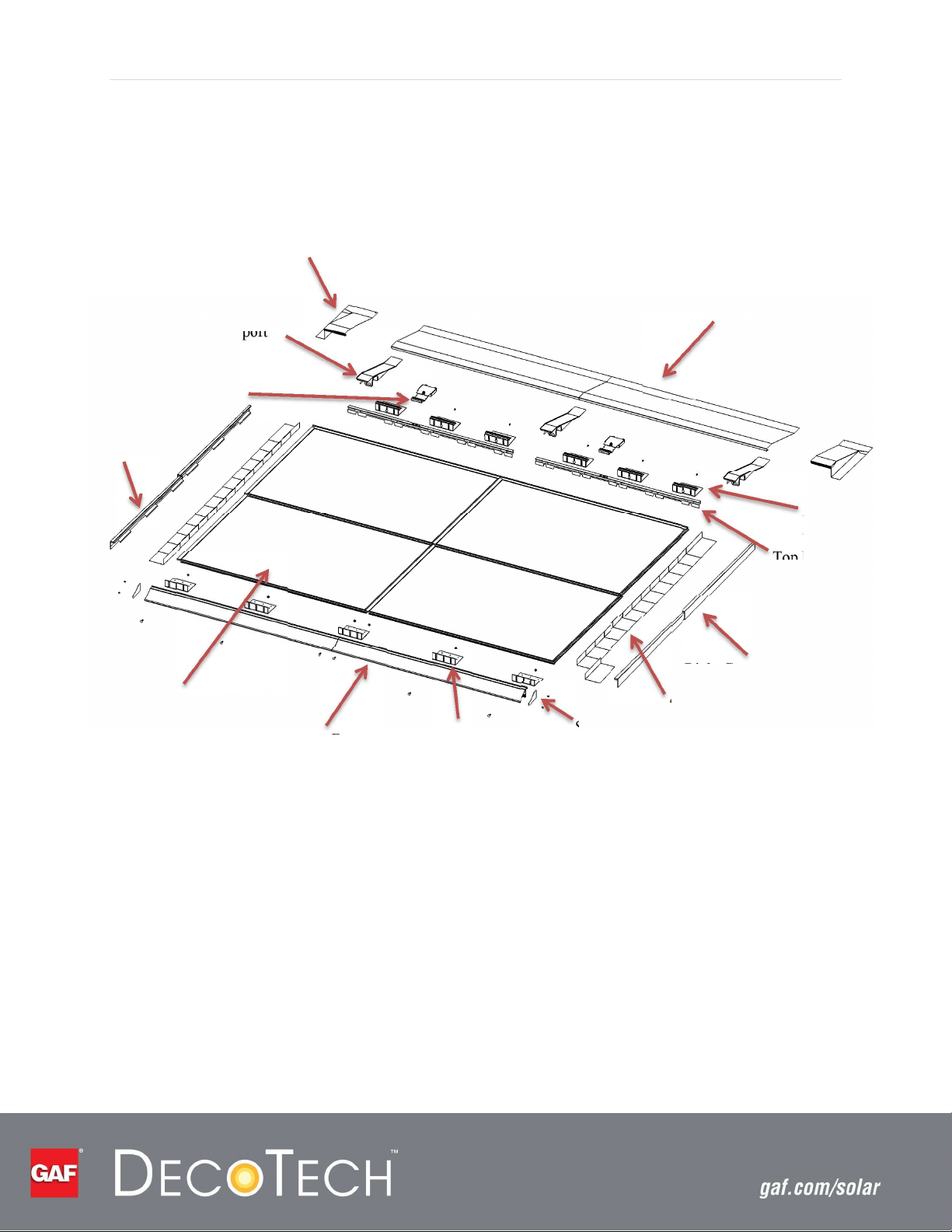
Figure 5 shows all of the hardware components that comprise GAF Solar Energy System.
Top Corner Flashing
Top Flashing
Support
MLP Bracket
w/Grounding Lug
Left Counterflashing
P a g e | 10
Top Flashing
Adjustable Foot
Module
Starter Bar
Adjustable Foot
Base
Figure 5 GAF Solar Energy System Components
Starter Bar
Cover
Top Flashing
Frame Insert
Right Counterflashing
Step Flashing
Page 11
COMPONENT
GAF SKU #
SILFAB
SOLARIA
Module
2947401
2947452
Starter Bar
2947405
2947441
Adjustable Foot Base
2947402
2947434
Starter Bar Cover
-
Left 2947412
2947446
Starter Bar Cover
-
Right
2947413
2947446
* Step Flashing
2947411
2947447
Counterflashing
-
Left 2947406
2947448
Counterflashing
-
Right
2947407
2947449
MLPE Bracket
2947404
2947436
Adjustable Foot
2947403
2947435
Top Flashing Frame Insert
2947415
2947445
Top Flashing Support
2947414
2947444
Top Flashing
2947408
2947450
Top Corner Flashing
-
Left 2947409
2947442
Top Corner
Flashing
-
Right
2947410
2947443
COMPONENT
MANUF
PART NUMBER
WEEB Grounding Lug
Wiley
WEEB
-
LUG-8.0 DynoBond™ Grounding
Jumper
-
38" DynoRaxx
DynoBond
-38
DynoBond™ Grounding
Jumper
-
76" DynoRaxx
DynoBond
-76
MLPE
TBD TBD
ITEM
GAF SKU #
VersaShield® SOLO™ Fire
-
Resistant Slip Sheet
905500
QuickStart® Peel & Stick Starter Roll
1122000ST
StormGuard® Film
-
Surfaced Leak Barrier
092500MV
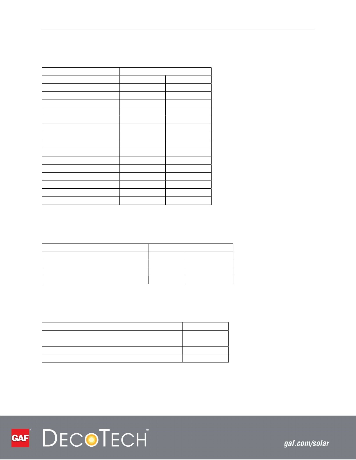
The SKU Numbers for GAF components are shown in Table 1 below.
Table 1 GAF SKU Numbers
P a g e | 11
* Left and Right Covers are the same.
Table 2 Non-GAF Components
The required GAF underlayment is listed in Table 3.
Table 3 GAF Underlayment
(Note: 3 foot wide roll)
Page 12
P a g e | 12
In addition to the above, the installer will need to provide the following typical Balance of System items:
Bare solid copper grounding wire
PV wire/jumpers
Wire and conduit for homeruns
Junction box
AC/DC Disconnect
Meter
Inverter
Roofing materials
o Shingles
o Shingle Underlayment
o Drip edge
o Shims
o Triangle Fastener Panel-Tite™ #14 – 1-1/2" (37.5 mm) heavy-duty roofing fasteners
o Cap nails/staples
Notes
Do not mix Solaria and Silfab GAF components.
The System can be designed with either a DC power optimizer or an AC Microinverter. Follow the
MLPE manufacturer’s installation instructions. Additional components may be required.
GAF recommends the use of factory-certified PV cables instead of field-crimping PV wire and
connectors.
If the installer wishes to use his or her own non-corrosive metal step flashing, the flashing must have
a vertical height of 2 inches (51 mm) up the side of the modules, be a minimum of 2 inches (51 mm)
longer up the roof than the exposure of the asphalt shingle being installed, and must extend
horizontally over the shingle on the roof a minimum of 5 inches (127 mm).
Except as noted, no substitutions are allowed without prior written approval from GAF.
Page 13
P a g e | 13
Solar Array Configurations
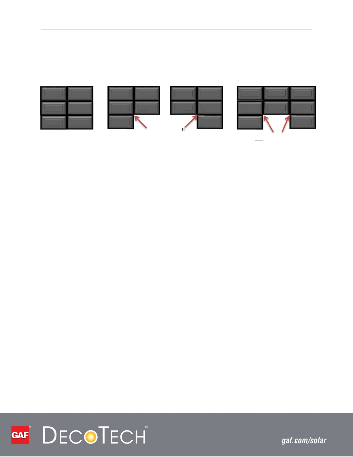
The solar array can be laid out in various shapes. The available configurations are shown in Figure 6. The
assembly instructions in Section 4 assume a rectangular Configuration “A” layout. Installation instructions
for the other configurations can be found in the Appendix (Page 59).
Left
Inside
Corner
Config A
Figure 6 Solar Arrray Configuations
Right
Inside
Corner
Config B
Left and Right Inside Corners
Config C
Page 14

P a g e | 14
SECTION 3 — GAF SOLAR ENERGY SYSTEM CONSIDERATIONS
AND REQUIREMENTS
Design Considerations
Slope limitations… The GAF Solar Energy System is intended for use solely on roofs having a slope
between 4:12 and 12:12.
Deck mounting… The GAF Solar Energy System is installed directly to the roof deck without
engaging rafters and requires underlayment as specified in these instructions. It cannot be
installed over shingles.
Deck thickness and fastening... The roof deck must be a minimum of 15/32 inches (11.9 mm)
thick plywood or 7/16 inches (11.1 mm) OSB decking as recommended by APA – The Engineered
Wood Association. Wood plank decking must be well-seasoned and supported having a maximum
1/8 inch (3 mm) spacing at the ends and sides using minimum nominal thickness 1 inch (25 mm)
x maximum 6 inches (152 mm) lumber. The decking must have adequate nail-holding capacity and
a smooth surface. Boards with a nominal thickness of 1 inch (25 mm) and a maximum width of 6
inches (152 mm) are also acceptable. Installers should ensure that the deck is properly fastened
per local building code requirements.
Landscape orientation… The GAF Solar Energy System is designed for landscape orientation only.
Solar Array wiring… Refer to the Permit Design Drawings for the system wiring details. The
system electrical design is outside the scope of this manual.
Operating temperature… The GAF Solar Energy System has an operating temperature range of -
40°F to +185°F (-40°C to +85°C).
DC electrical output... Under certain environmental conditions, the GAF Solar Array may produce
more current and/or voltage than reported at standard test conditions (irradiance of 1000 W/m²,
AM 1.5 spectrum, and a cell temperature of 25°C [77°F]). The solar designer should account for
these conditions when designing the solar array.
Suitable ambient conditions… Artificially concentrated sunlight shall not be directed on the Solar
Array. The modules must neither be immersed in water nor be exposed to continuous wetting
(e.g. by fountains). Exposure to salt or sulfur (sulfur sources, volcanoes) implies a risk of corrosion.
The system must not be used for maritime (e.g. boats) or automotive (vehicles) purposes. The
system must not be exposed to extraordinary chemical loads (e.g. emissions from manufacturing
plants). The GAF Solar Energy System should not be installed on stables.
Paint... Do not apply paint to any part of the GAF Solar Energy System.
Roof Setbacks... The GAF Solar Energy System requires the installation of a minimum of two full
rows of shingles at the eave and the ridge. The minimum allowable offset to the rake is 18" (457
Page 15

P a g e | 15
mm). Please refer to the local building and fire codes for additional setback and pathway
requirements.
Mounting hardware… The GAF Solar Energy System is intended to be mounted to a roof using
only the hardware provided. Using other unapproved means is a violation of the UL listing and
will impact the GAF warranty.
Design loading… Refer to Table 6 (Page 57) for the allowed mechanical loading of the GAF Solar
Module Assembly.
Fire classification… The GAF Solar Energy System has been rated as Class A for resistance to
external fire exposure per UL 2703 when used with the following underlayment:
1. One ply of self-adhered StormGuard® Film-Surfaced Leak Barrier
2. One ply of VersaShield® SOLO™ Fire-Resistant Slip Sheet, mechanically fastened with
plastic cap nails or staples.
For roof mounting, the acceptability of the completed assembly, including the fire resistance of
the underlying components of the roof, shall be evaluated per local fire codes.
Solar trackers… The GAF Solar Energy System has not been evaluated for use on a solar tracker.
Nonstructural component… These products have been evaluated for serving as a nonstructural
component of a building only. They are not intended to serve as a primary component of the
building’s exterior surface. The supporting structure (integrated racking) provided with these
systems can only support the solar laminate.
PV laminate specific... The GAF Solar Module Assembly may be used to ground and/or mount a
PV laminate complying with UL 1703 only when the specific module has been evaluated for
grounding and/or mounting in compliance with the included instructions. The Solaria PowerXT
and the Silfab SLA-M laminates have been evaluated for use on the GAF PV Mounting System.
Wiring accessibility… These products and associated wiring must not be accessible from the
interior space of the building. NEC procedures for installation of wiring must be followed.
Roof obstructions… Do not install any portion of the solar system over any roof obstructions,
plumbing, or attic vents. Do not attempt to cut or modify the Solar Module Assembly to
accommodate any roof projections. Roof obstructions must be removed or relocated to another
area of the roof.
Attic ventilation… If the GAF Solar Energy System covers a large area of the roof, proper attic
ventilation and moisture control must be considered.
Ice dams… Do not install the GAF Solar Energy System near areas of the roof that are prone to ice
damming.
Shingle mismatch… When installing a GAF Solar Array on an existing roof, all the shingles in the
plane of the roof with the solar array must be removed and replaced with GAF Shingles. New
shingles used in the plane of the installed solar array may not initially match existing shingles in
Page 16

P a g e | 16
the other roof planes due to weathering and available colors for new shingles. However, color
variation may diminish over time.
Installation Requirements
Safety first… Follow all of the safety precautions outlined in Section 1.
Follow roofing best practices… Follow all related GAF Shingle application instructions and
industry best practices. Special attention is needed when stripping the shingles, installing
underlayment, and flashing around the GAF Solar Energy System.
Installation direction… each row of Solar Module Assemblies is positioned from left to right and
then attached to the deck from right to left. Rows are installed from bottom to top.
Obtain permits… The installer must comply with local, regional, and national building codes (IBC,
IFC, NEC, etc.) and obtain necessary permits and approvals from the local jurisdiction prior to
installing the GAF Solar Energy System.
Contact local utility… Contact your local power provider for grid connection requirements prior
to the system design and installation.
Deck-height variations… Repair roof if deck-height variation (either a peak or valley) is greater
than 0.75 inches (19 mm) over a 4' (1,219 mm) span between trusses.
Water damage… Replace water-damaged sheathing (if any).
Relocate obstructions… Relocate rooftop obstructions that are directly under the planned solar
array location.
Page 17
P a g e | 17
Grounding
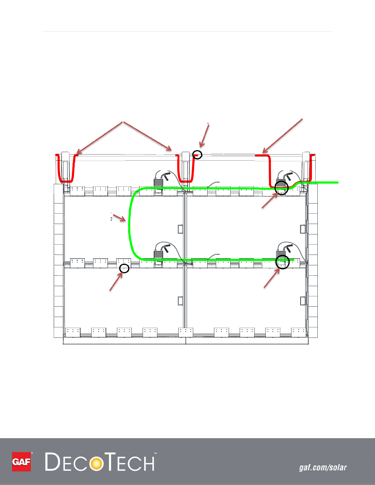
Figure 7 below summarizes the GAF Solar Energy System grounding requirements and components.
Details of the assembly steps are covered in Section 4.
38” DynoBond™ Jumper
See
Figure 11
76” DynoBond™ Jumper
To System
Grounding
Point
Solid Copper
Ground Wire
See
Figure 9
Figure 7 GAF Solar Energy System grounding requirements
See
Figure 12
See
Figure 8
A continuous bare solid copper conductor is strung throughout the solar array connecting each MLPE
bracket and provides the connection to the system’s main grounding point. (See Permit Design Drawings
for details on this terminating connection.) Each GAF Solar Module Assembly is bonded to the solid copper
ground wire through the MLPE bracket using a UL Listed WEEB® Grounding Lug and Washer (WEEB®-LUG-
8.0) as shown in Figure 8 below.
Page 18
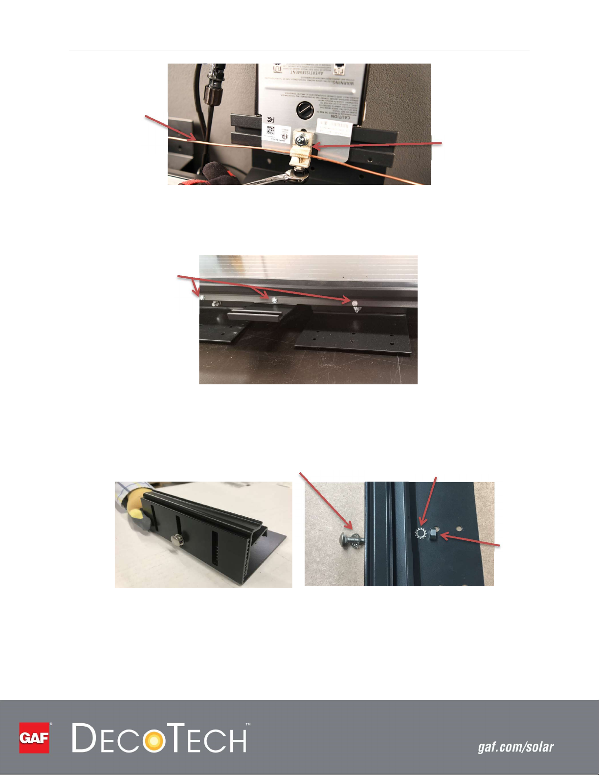
®
Bare Solid Copper
Grounding Wire
P a g e | 18
WEEB
Assembly
Grounding
Figure 8 Bonding GAF Solar Module Assembly to Copper Wire
The adjustable feet and MLPE bracket are bonded to the GAF frame with the provided hex grounding
screw (10-32x3/8”, serrated washer, thread cutting type F) as shown in Figure 9 below.
Grounding Screw
Figure 9 Feet and bracket bonding screw
The two parts of the Adjustable Foot Assembly are bonded together via the provided hardware as shown
in Figure 10 below.
Internal Tooth
Washer
Figure 10 Adjustable Foot Bonding Hardware
External Tooth
Washer
Serrated Nut
The Top Flashing and Top Corner Flashing are bonded together using UL-approved DynoRaxx®
DynoBond™ Grounding Jumpers as shown in Figure 7 above. A single 38" DynoBond™ is used between
two flashing pieces. The 76" DynoBond™ is used in one location to provide bonding between the flashing
pieces and the bare copper system ground wire. Figure 11 below shows how the DynoBond® clip attaches
to the flashing piece. Figure 12 shows the connection between the 76” DynoBond® jumper and bare
copper wire at one of the MLPE WEEB® Ground Lugs.
Page 19

P a g e | 19
Top Flashing
DynoBond™ Clip
WEEB® Grounding
Assembly
Figure 11 DynoBond™ clip connection to flashing
Figure 12 Connection between DynoBond™ Jumper and copper ground wire
MLPE
Page 20
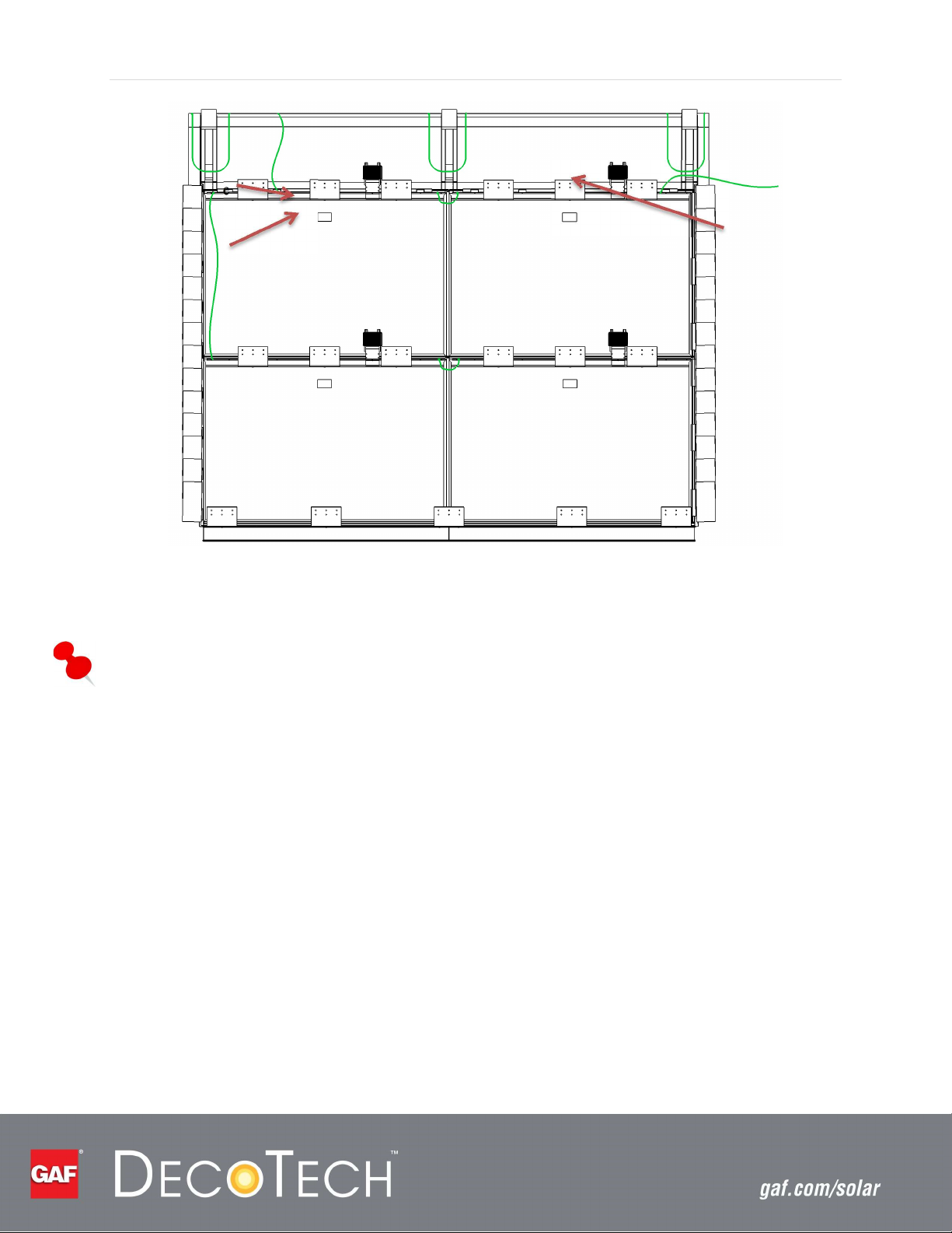
Bare Solid
Copper Wire
76" DynoBond™
Jumper
P a g e | 20
MLPE Foot
Figure 13 Alternate system configuration using DynoBond™ clips in place of ground wire
Alternatively, the system can be gounded using only DynoBond™ clips and omitting a traditional ground
wire. For full instructions including how to use a DynoBond™ clip to ground the system, refer to the full
Dynobond™ install manual (DynoRaxx document number 070919).
Notes
The grounding hardware for the Adjustable Foot Assembly (Figure 10) can be reused up to 3 times.
The grounding screws for the Adjustable Feet and MLPE bracket (Figure 9) are single-time use
only.
The DynoBond™ clips (Figure 11) are single-time use only.
No more than two 10-14 AWG wires can be used in the Weeb® Grounding Lug (Figure 12). See
manufacturer’s instructions.
Systems that do not use an MLPE (i.e. use a string inverter instead) must still install the MLPE
bracket and WEEB® Grounding Lug for proper system grounding.
Use only UL-approved methods for splicing the solid copper ground wire
Page 21
P a g e | 21
Recommended Tools
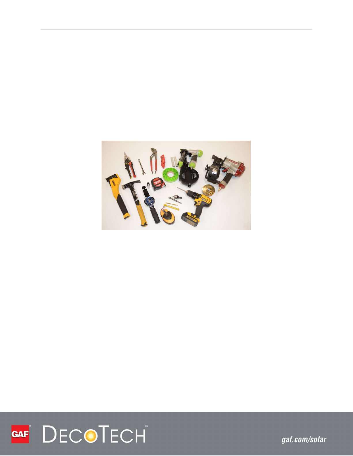
The following tools (Figure 14) are recommended to properly install a GAF Solar Energy System (this list
is representative only; additional tools may be required depending on the installation):
Cordless drill
5/16" (8 mm) Hex driver bit (for the deck screws, solar foot and GND screw)
#2 Phillips driver bit (for TE grounding clip and starter bar cover)
1/2" (13 mm) socket (for MLPE screw and S-8 split-bolt)
7/16" (11 mm) wrench
Chalk line
Torque wrench
Figure 14 Typical Tools Required
Figure 14: Recommended Tools
Page 22

P a g e | 22
Prior to Installation
The following should be completed prior to the installation of the GAF Solar Energy System:
Review documentation… Review the installation instructions and Permit Design Drawings thoroughly.
Ensure materials are onsite… Ensure that all the correct materials in the appropriate quantities are
present onsite.
Display permits… Ensure all building/electrical permits are posted in a visible location onsite.
Discuss with the building owner… Confirm access roads, material staging area, and ladder access area
(as shown in the Permit Design Drawings). Also discuss work hours, installation noise, and electrical
panel shutdown timing with the building owner.
Review site… Review pre-existing site conditions prior to installation. If the installer notices any
abnormalities in pre-existing site conditions, do NOT proceed with the installation until the matter is
resolved with the building owner and with GAF. Typical abnormalities include:
o Situations where site conditions do not match planned design
o Roof obstructions
o Excessive deck-height variations
Page 23
P a g e | 23
SECTION 4 — GAF SOLAR ENERGY SYSTEM INSTALLATION
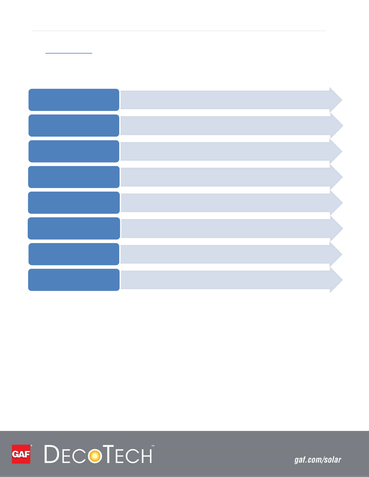
The following steps outline the procedure to install the GAF Solar Energy System and are described in this
Section:
Step 1
Step 2
Step 3
Step 4
Step 5
Step 6
Step 7
•Prep the Roof
•Build the Starter Bar and the Solar Module Assembly
•Install the Starter Bar
•Install the First Row of Solar Module Assemblies
•Install the Remaining Rows of Solar Module Assembles
•Install Side Flashing
•Install Top Flashing
Step 8
•Install Top Flashing Underlayment and Shingles
Page 24
Step 1: Prep the Roof
Follow the sequence below to complete this step.
P a g e | 24
Step 1a: Prep and Clean the Deck
Step 1e: Install QuickStart® Peel and Stick Starter Roll Step 1f: Install VersaShield® SOLO™ Underlayment
Step 1a: Prep and Clean the Deck…
Step 1b: Install Roofing
Componets on Eves
and Rakes
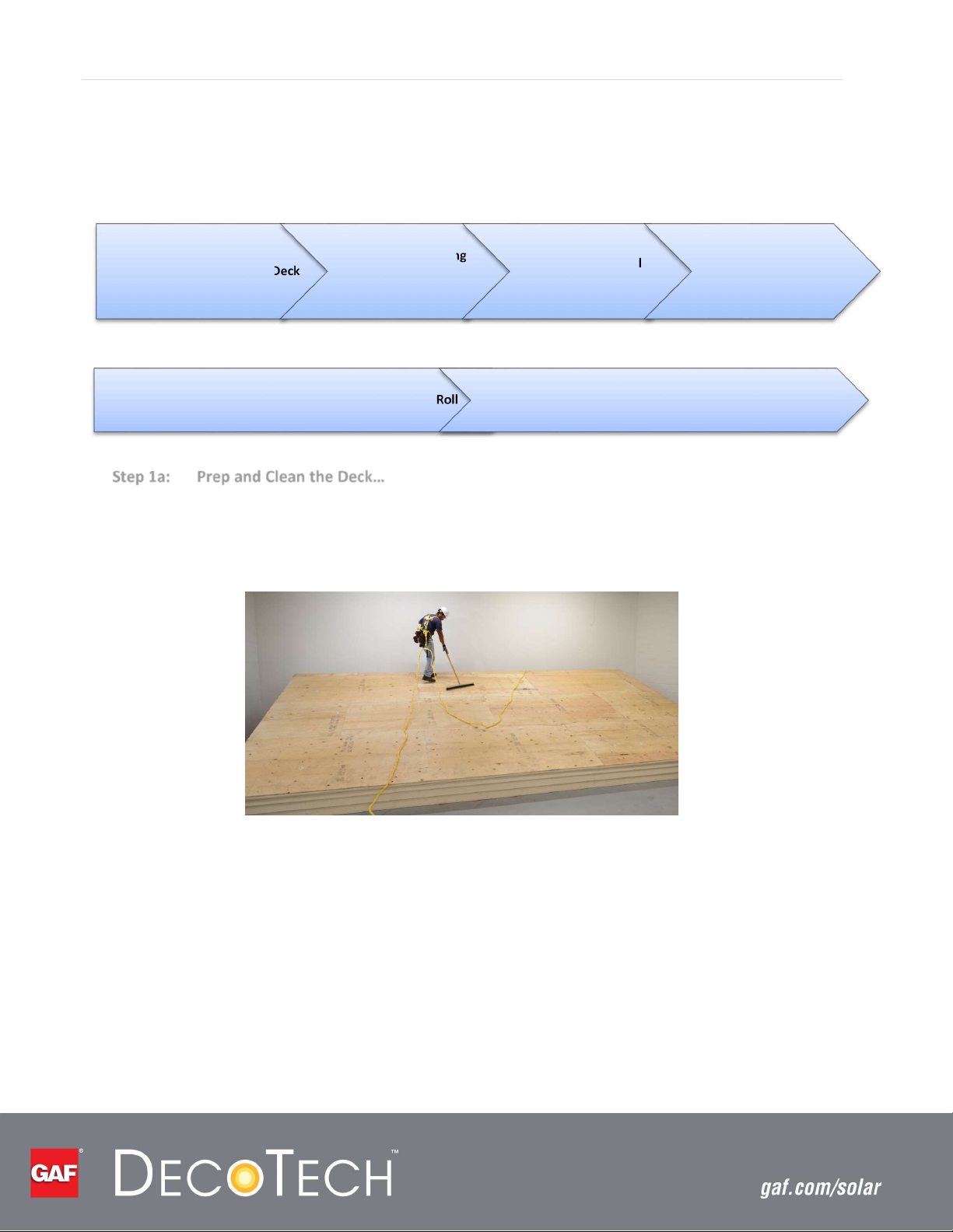
For new roofs, start with a clean plywood/OSB deck. For existing
Step 1c: Install Initial
Rows of Shingles
Barrier Underlayment
roofs, proceed with a roof tear-off and clear the existing deck of all shingles and underlayment
in the plane of the planned solar array. Remove or hammer in all protruding nails on the deck
and prepare a smooth and level deck surface. Sweep away dirt and debris from the roof deck
(Figure 15).
Step 1d: Install
StormGuard Leak
Figure 15 Prep and clean the deck
Step 1b: Install Roofing Components on Eaves and Rakes… Install a drip edge, leak barrier, and starter
roll along the eaves and rakes using industry best practices. Refer to the latest version of the
GAF Steep Slope PRO Field Guide for guidance.
Step 1c: Install Initial Rows of Shingles up to Planned Location of the Starter Bars... Using the Permit
Design Drawings, determine the number of rows of shingles required between the eave and
the Starter Bars. Locate and mark the lower-left corner of the solar array. The starting point
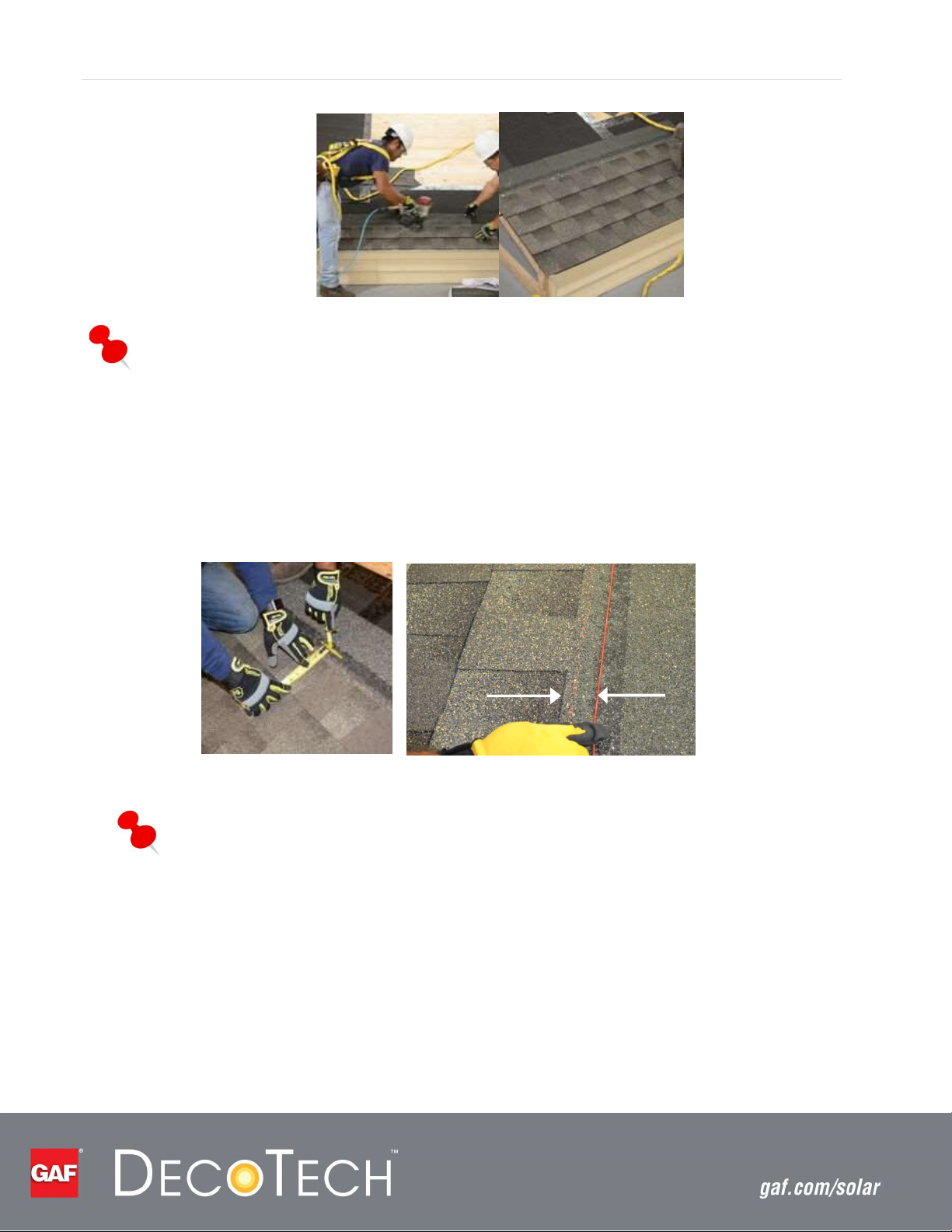
must always land within the shingle headlap area. For example, in Figure 16 below, four rows
of shingles are required to reach the starting point.
Page 25
P a g e | 25
Figure 16 Install initial rows of shingles
Note
The GAF Solar Energy System requires a minimum two rows of shingles to be installed at the eave.
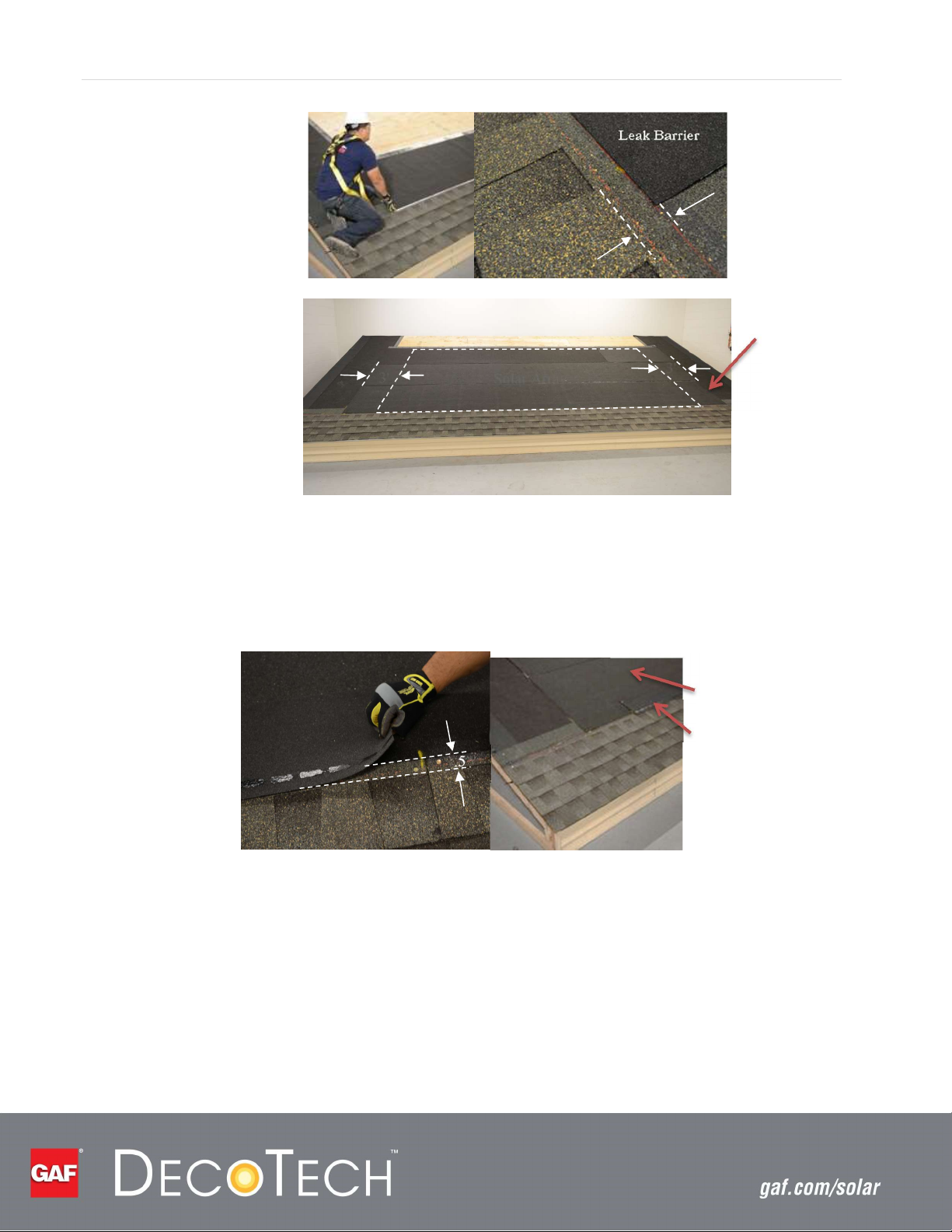
Step 1d: Install the Leak Barrier Underlayment in the Field of the Solar Array... Begin by snapping the
following chalk lines on the deck:
Snap a line 1.5" (38 mm) up from the top of the exposure of the last row of shingles
installed (Figure 17).
Snap a line marking the left, right, and top edge of the solar array.
1.5"
Figure 17 Snap a chalk line along the array starting point
Note
Confirm that all measurements and setbacks comply with the Permit Design Drawings.
Roll out the StormGuard® Leak Barrier, aligning its edge with the chalk line over the shingle
headlap. Extend the leak barrier 3 feet (914 mm) beyond the left and right sides of the solar
array (Figure 18).
Page 26
P a g e | 26
1.5"
Leak Barrier
3'
Solar Array
3'
Figure 18 Install the leak barrier underlayment
Step 1e: Install QuickStart® Peel and Stick Starter Roll... Install the QuickStart® Peel and Stick Starter
Roll over the shingle headlap, covering the 1.5 inch (38 mm) gap between the leak barrier and
the top of the shingle exposure (Figure 19). The QuickStart® Peel and Stick Starter Roll should
be the same width as the solar array.
Leak Barrier
QuickStart®
1.5
"
Peel and Stick
Starter Roll
Figure 19 Install QuickStart
®
Peel & Stick Starter Roll
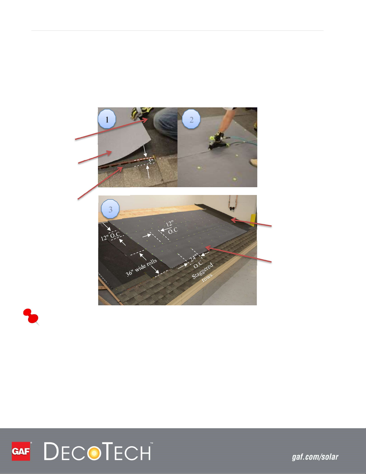
Step 1f: Install the VersaShield® SOLO™ Fire-Resistant Slip Sheet in the Field of the Solar Array... The
VersaShield® SOLO™ Fire-Resistant Slip Sheet should be installed over the StormGuard® Leak
Barrier and the QuickStart® Peel and Stick Starter Roll, leaving the same 1.5 inch (38 mm) gap
between the shingle headlap and the edge of the slip sheet (Figure 20). To fasten, use
corrosion-resistant plastic cap nails or staples with plastic caps. The Slip Sheet should be the
same width as the solar array.
Page 27
1 2 3
Leak Barrier
P a g e | 27
For slopes between 4:12 and 6:12, side and end laps should be fastened 12 inches (305 mm)
on center (o.c.) and 24 inches (610 mm) o.c. elsewhere. Stagger each row of 12 inches spaced
fasteners. The side lap should be overlapped 3 inches (76 mm) and end lap 6 inches (152
mm).
For slopes greater than 6:12, side and end laps should be fastened 9 inches (228 mm) o.c. and
18 inches (457 mm) o.c. elsewhere. Stagger each row of 9 inches spaced fasteners.
VersaShield®
SOLO™ Fire-
Resistant Slip
Sheet
QuickStart®
Peel and Stick
Starter Roll
1.5"
Leak Barrier
VersaShield®
SOLO™
Fire-Resistant
Slip Sheet
Figure 20 Install VersaShield SOLO Fire-Resistant Slip Sheet
Note
To avoid interference with the Starter Bar, do not install the first row of cap nails along the lower
edge of the VersaShield® SOLO™ Fire-Resistant Slip Sheet.
Page 28
Step 2: Build the Starter Bars and the Solar Module Assemblies
Follow the sequence below to complete this step.
Step 2a: Assemble the Starter Bars Step 2b: Install the Adjustable Feet Step 2c: Install the MLPE Brackets
P a g e | 28
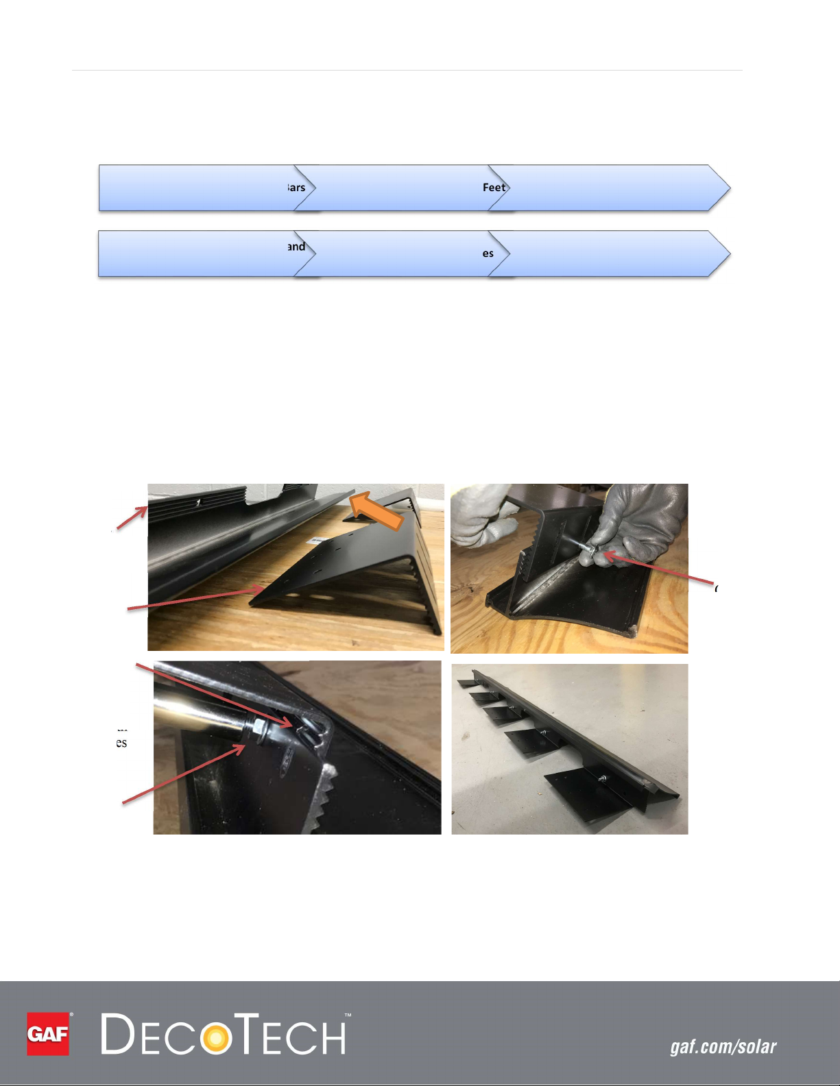
Step 2a: Assemble the Starter Bars... Each Starter Bar receives 3-5 Adjustable Feet Bases (check the
Starter Bar
Adjustable
foot base
Step 2d: Install the WEEB® Lug and
MLPE
approved system drawings for your installation) which are attached using the provided
carriage bolts (5/16"-18 x 1" Steel, Zinc Plated) and nuts (Flanged, 0.313''-18, Steel, Zinc
Plated). The tooth grooves of the Adjustable Foot Base should align with the tooth groves of
the Starter Bar. Use the factory-assembled position of the Adjustable Foot (above the second
tooth) by default. Torque the nut to 75 inch-pounds (8.5 Nm) See Figure 21 below. Note
that adjacent Starter Bars share a common foot as shown in Figure 22 below. Please refer to
the Permit Design Drawings for the Starter Bar arrangement.
Step 2e: Connect the PV Wires
Step 2f: Ensure Proper Wire
Management
Carriage
Bolt
Default height
of the
adjustable foot
base is to
expose 2 tooth
grooves
Nut
Figure 21 Assembling the Starter Bar
Page 29
P a g e | 29
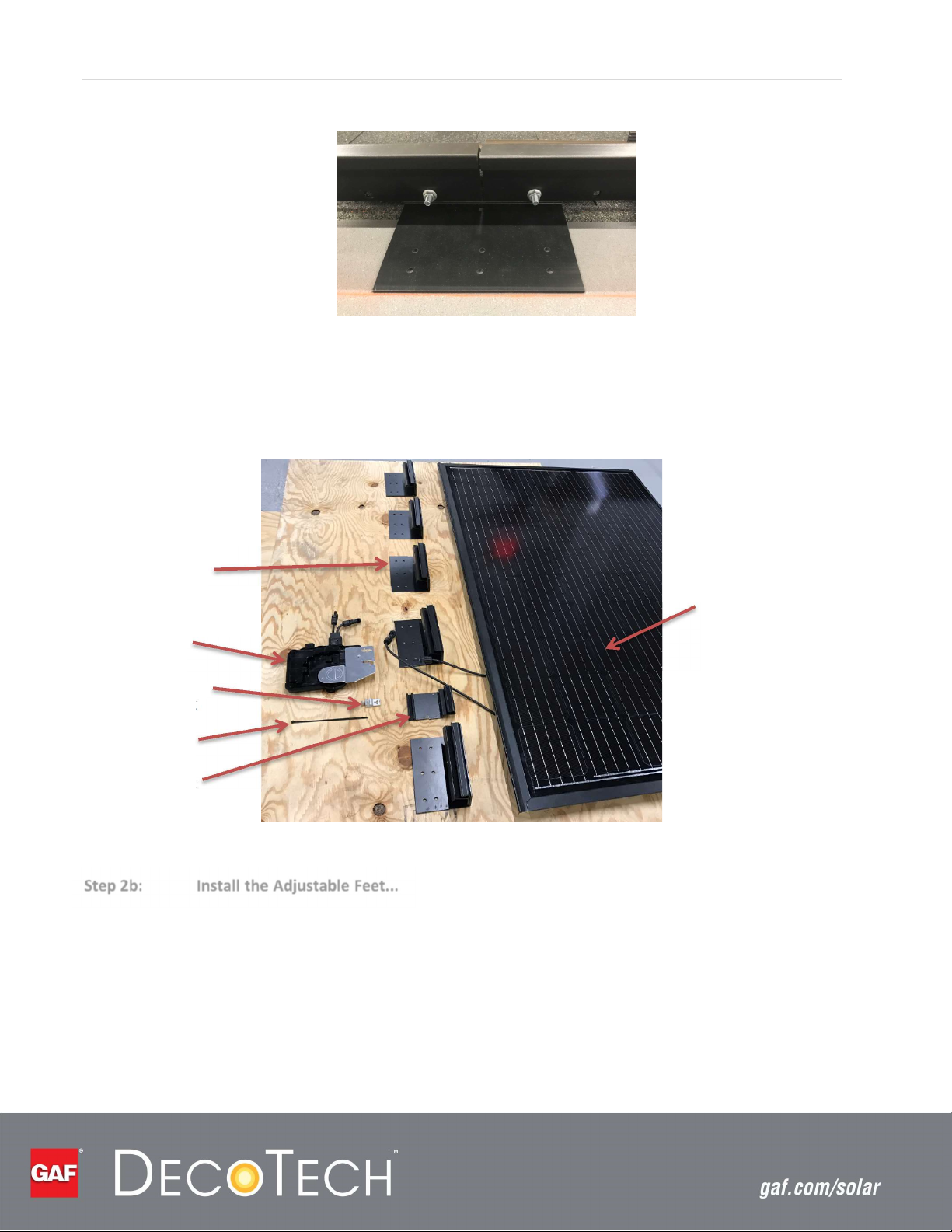
Figure 22 Splice between adjacent Starter Bars
The GAF Solar Module Assembly is composed of the parts shown in Figure 23 below. Steps 2b-2f
describe the steps necessary to complete this assembly. The completed assembly is shown in Figure
31 on Page 33.
Adjustable Feet
(x5)
MLPE
(Typical)
WEEB®
Grounding Lug
Wire Ties
MLPE bracket
Figure 23 GAF Solar Module Assembly
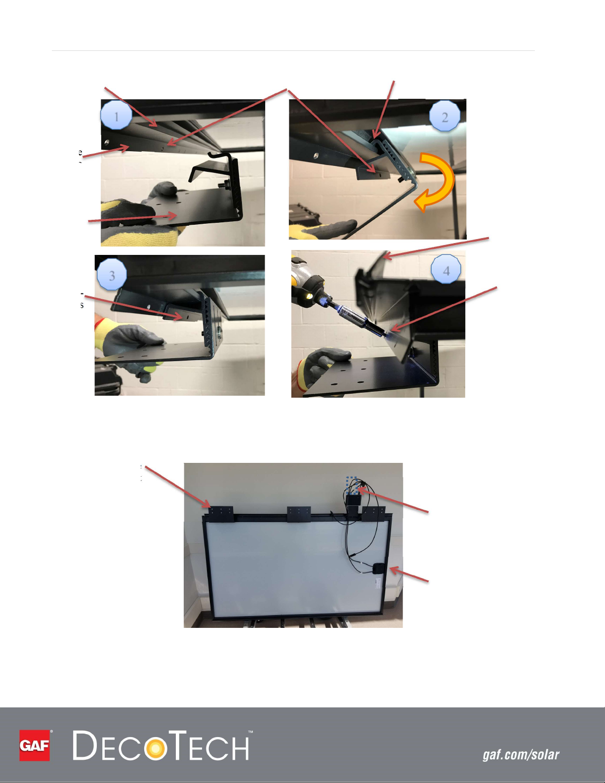
Step 2b: Install the Adjustable Feet...
local regulations and environmental conditions. Check the approved system drawings for your
installation to determine the proper number. After hooking the Foot onto the channel along
the solar module frame, rotate it into position and align the pre-drilled hole. Attach the Foot
using the hex grounding screw into the pre-drilled hole (Figure 24, next page). Torque the
screw to 40 inch-pounds (4.5 Nm). Repeat this step until all the Adjustable Feet are installed
as shown in Figure 25.
Module
Each solar module receives 3-5 Adjustable Feet, depending on
Page 30
P a g e | 30
Pre-drilled Holes
1
2
3
4
Channel
Solar Module
Frame
Adjustable Feet
Align the Pre-
drilled Holes
Hook onto the Channel
and Rotate
Wiper Seal
Grounding
Screw
Adjustable
Feet
Figure 24 Mounting the Adjustable Foot
MLPE bracket location
Module Junction Box
Figure 25 Completed GAF Solar Module Assembly
Page 31
P a g e | 31
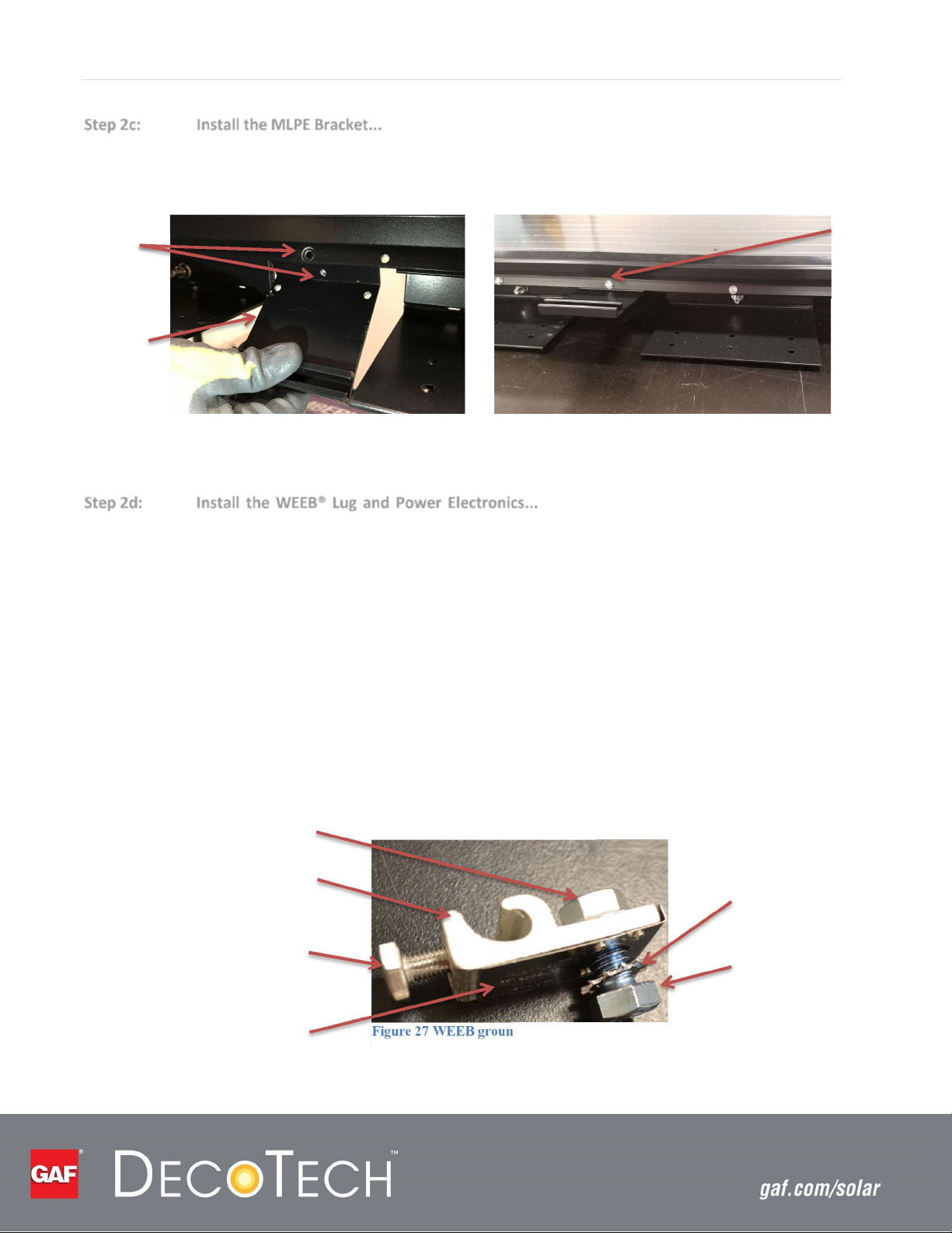
Step 2c: Install the MLPE Bracket...
. Position the MLPE Bracket in between the Adjustable Feet on the
junction box end of the module as shown in Figure 25. The MLPE bracket is installed in the
same manner as the adjustable feet. Align the predrilled holes and attach the Bracket onto
the frame using the grounding screw. (Figure 26 below).
Align the
Pre-
Drilled
Holes
MLPE
Bracket
Figure 26 MLPE bracket installation
Step 2d: Install the WEEB® Lug and Power Electronics...
Grounding Lug and the MLPE onto the MLPE bracket.
Build the WEEB® grounding assembly as shown in Figure 27. Leave the flange nut
loose for now. The WEEB® assembly consists of the following:
o 5/16"-18 x 3/4" Hex Cap Screw, zinc
o 5/16" External Tooth Washer
o WEEB® Washer
o WEEB® Grounding Lug
o WEEB® 1/4"-20 Hex Cap Screw, SS (WEEB® Terminal Screw)
o 5/16"-18 Flange Nut, Zinc.
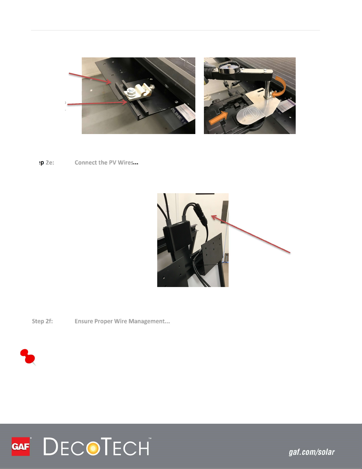
Slide the WEEB® assembly into the slot of the MLPE foot and center it (Figure 28).
Slide the MLPE under the WEEB® Washer and tighten the flange nut to 120 inch-
pounds (13.5 Nm) (Figure 28).
Flange Nut
Grounding
Screw
. Follow these steps to mount the WEEB®
WEEB®
Grounding Lug
WEEB® Terminal
Screw
WEEB® Washer
Figure 27 WEEB grounding assembly
External Tooth
Washer
Hex Cap Screw
Page 32
MLPE
Bracket
WEEB®
Grounding
Assembly
Step
2e: Connect the PV Wires...
MLPE.
P a g e | 32
Figure 28 Attach WEEB Ground Assembly to MLPE
Connect the module cables to the mating connectors on the
Figure 29 Attach connectors
Step 2f: Ensure Proper Wire Management...
. It is critical to ensure that no wires come in contact with
any of the Side Flashing of the array. Secure the wires to the MLPE bracket and module frame
as needed. See Figure 30.
Note
Do not exceed the cables’ minimum bend radius. See NEC for details.
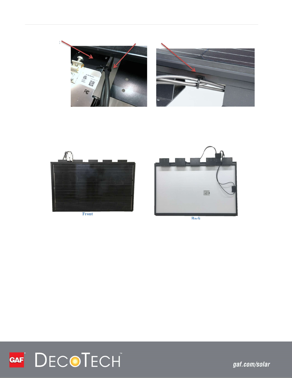
Wiring
Connectors
Page 33
P a g e | 33
MLPE Bracket
Wire Ties
Figure 30 Proper wire management.
Figure 31 shows the front and back of the completed GAF Solar Module Assembly.
Front
Figure 31 Completed Module Assembly
Back
Page 34
Step 3: Install the Starter Bar
Follow the sequence below to complete this step.
P a g e | 34
Step 3a: Snap Chalk Line
Step 3b: Position and Attach the Starter Bars to
the Deck
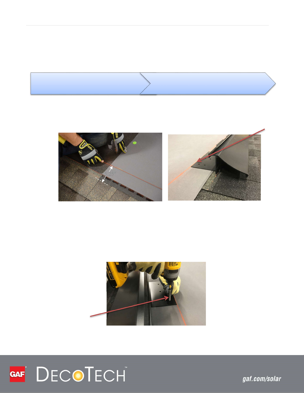
Step 3a: Snap Chalk Line… Snap a chalk line 5.25 inches (133 mm) from the edge of the shingle
exposure line (Figure 32).
5.25"
Figure 32 Position the first Starter Bar
Step 3b: Position and Attach the Starter Bars... Align the top edge of the feet of the Starter Bars with
the chalk line as shown in Figure 32. Each Foot has two rows of three pre-drilled screw holes.
Use either row of screw holes to avoid seams and knots in the roof deck. Fasten the starter
bar to the deck using #14 – 1-1/2" (37.5 mm) Panel-Tite™ Roofing Fasteners (Figure 33). Do
not overtighten the roofing fasteners.
Align the
Mounting
Foot with the
Chalk Line.
Panel-Tite™
Roofing Fasteners
(x3)
Figure 33 Attach the Starter Bar to the deck
Page 35
P a g e | 35
Note
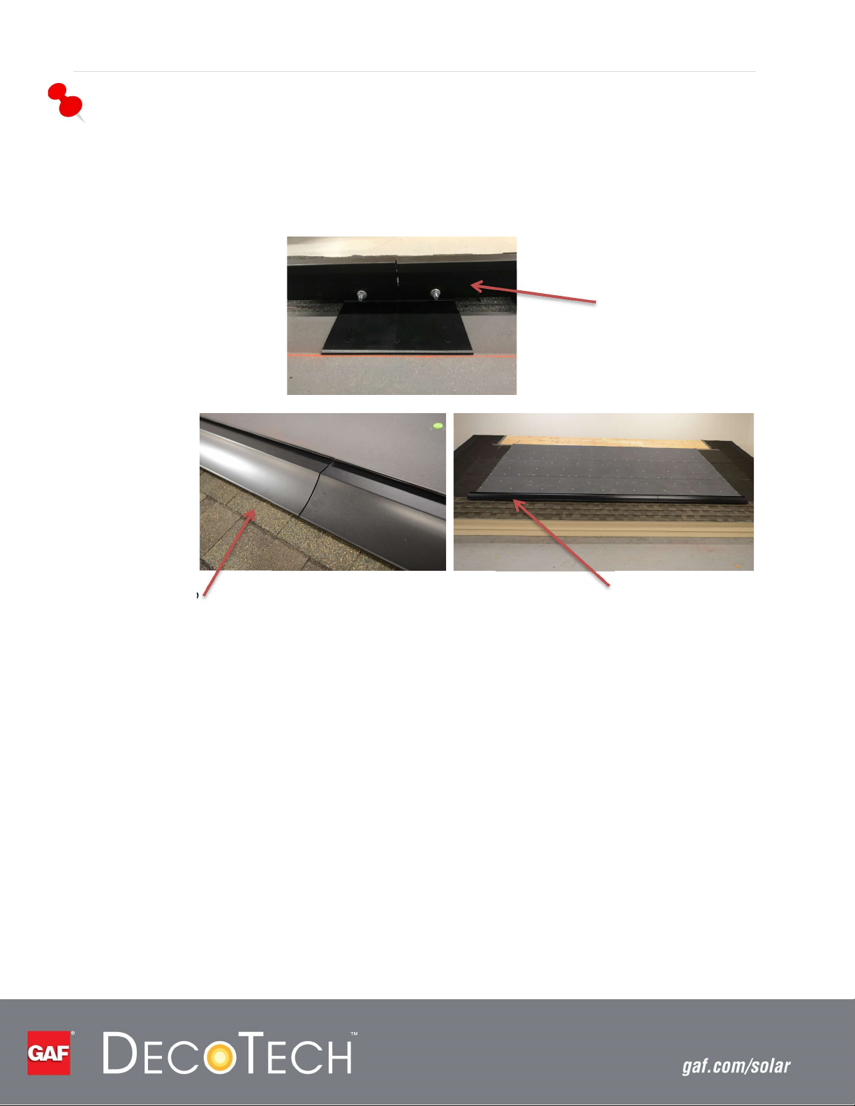
Because adjacent Starter Bars are spliced together using a common Foot Base, it is typically easier to
assemble all of the Starter Bars together before attaching them to the deck. This allows the entire
row to be aligned at once (Figure 34 ).
Adjacent Starter
Bars share Foot
Base
Gap
Figure 34 Row of Starter Bars
Starter Bars
Stretch a mason line along the top edge of the Start Bars to verify that everything is at the
same height (Figure 37). Adjust the feet as necessary (Figure 38).
Page 36
Step 4: Install the First Row of Solar Module Assemblies
Follow the sequence below to complete this step.
P a g e | 36
Step 4a: Mount the Solar Module
Assemblies onto the Starter Bar
Step 4b: Make
Electrical Connections
Between MLPEs
Step 4c: Attach the
Solar Module
Assemblies to the
Deck
Step 4d: Install
Grounding
Step 4e: Create the
MLPE Map
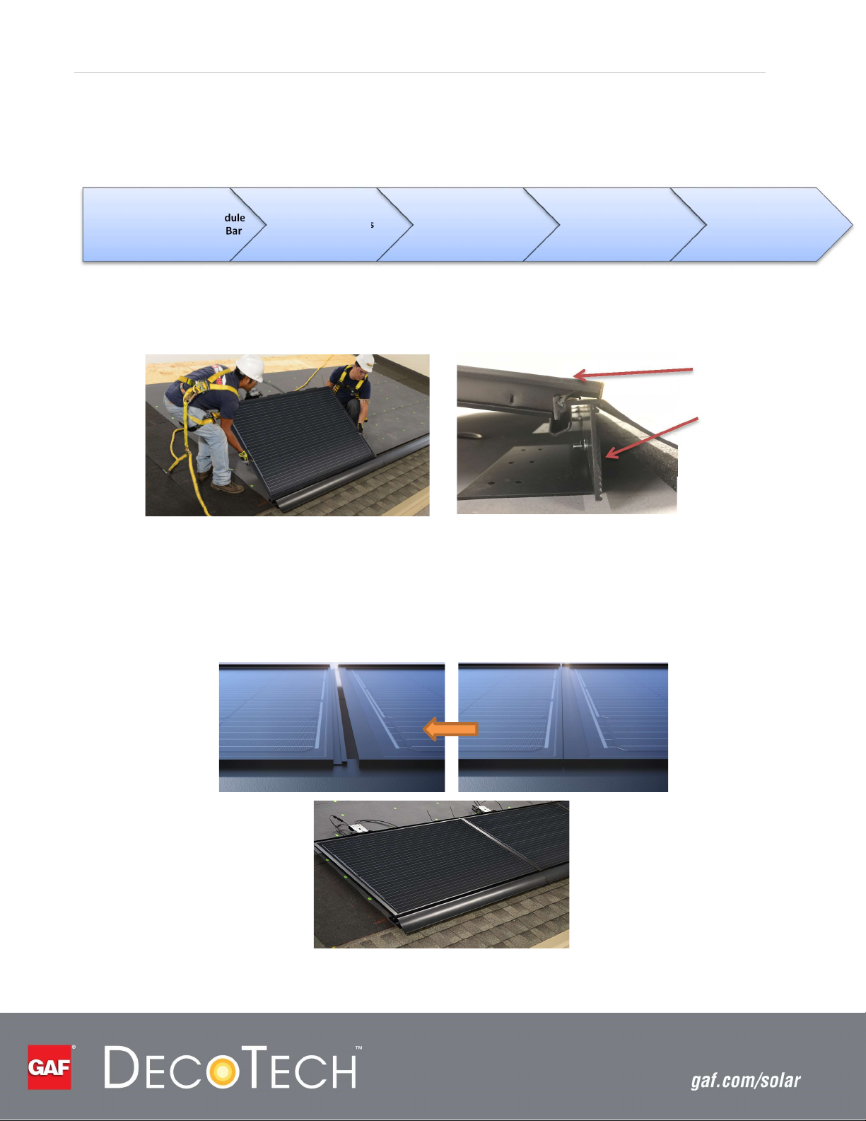
Step 4a: Mount the Solar Module Assemblies onto the Starter Bar... Place the Solar Module
Assemblies into the Starter Bars from left to right. Holding the Solar Module Assembly at ~15°
angle, slide it downward until it hooks into the starter bar (Figure 35).
Solar Module
Assembly
Starter Bar
Figure 35 Mount Solar Module Assembly onto the Starter Bar
Align the first Solar Module Assembly with left edge of the Starter bar. Place the next Solar
Module Assembly into the Starter Bar a few inches to the right of the first Solar Module
Assembly. Slide it to the left until it interlocks with the first Solar Module Assembly (Figure
36). Repeat these steps from left to right until the row is complete.
Figure 36 Placing and Aligning Solar Module Assemblies
Page 37
P a g e | 37
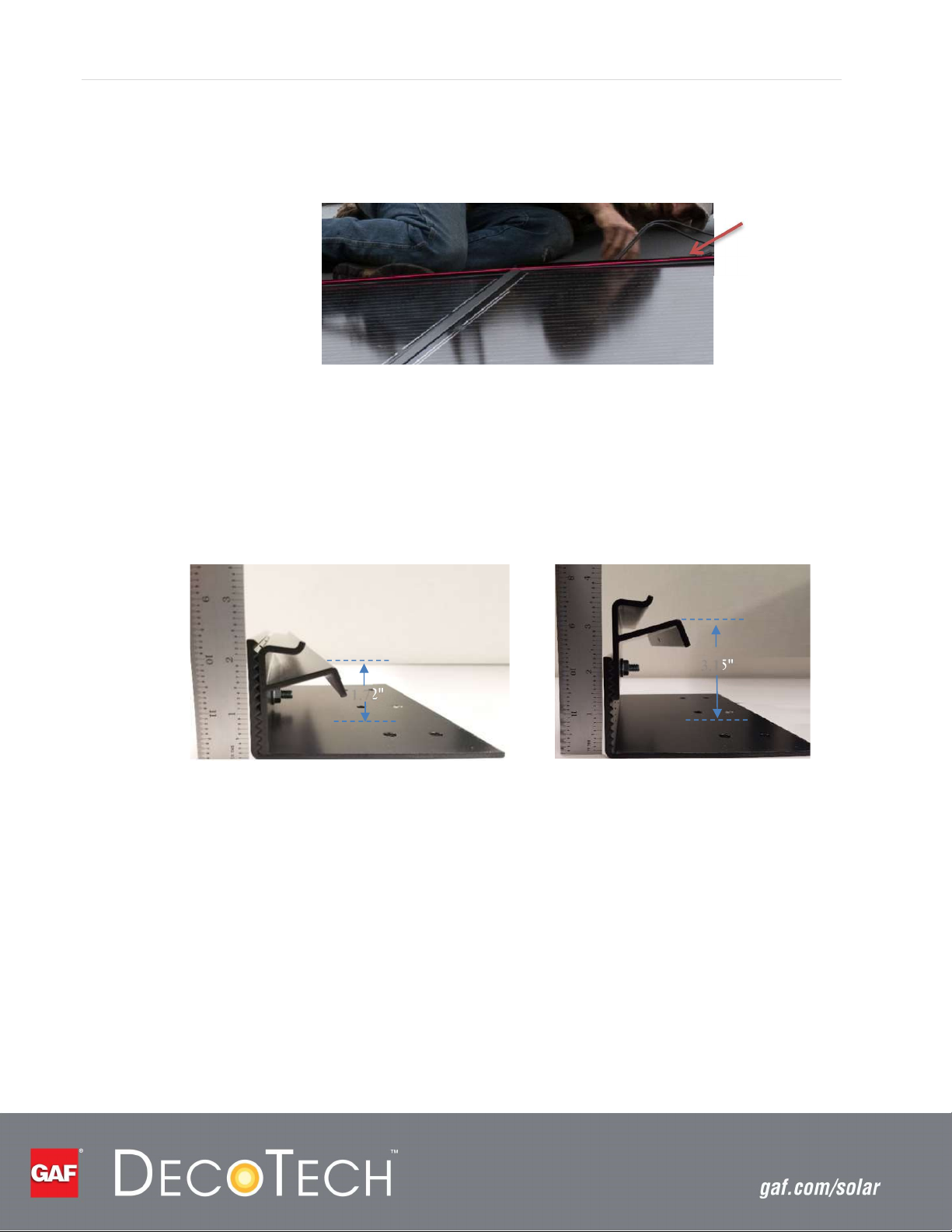
Stretch a mason line along the top edge of the row of Solar Module Assemblies to verify that
all of the Assemblies are at the same height (Figure 37). Adjust the feet as necessary.
Mason Line
along the Top
Edge of Solar
Module
Assemblies
Figure 37 Checking Height of Solar Module Assemblies
The height of the foot can be adjusted from a minimum 1.72 inches to a maximum 3.15 inches.
(Figure 38). If height adjustments are needed:
1. Loosen the carriage bolt and nut.
2. Align the interface to the correct tooth groove height
3. Retighten the carriage bolt and nut to 125 inch-pounds (14.12 Nm). The nut may be
re-torqued up to 3 times when adjusting the height.
3.15"
1.72"
Figure 38 Foot Adjustment Range
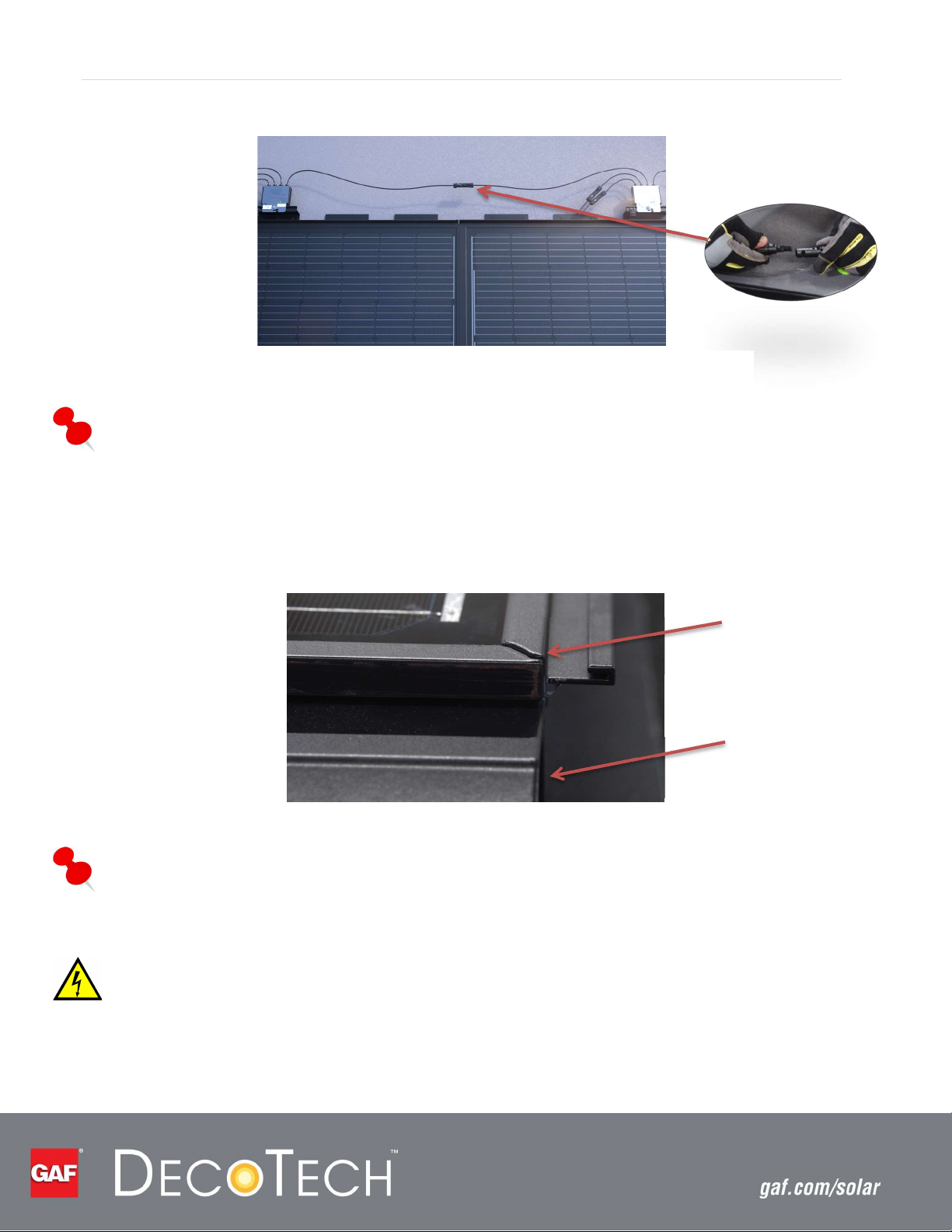
Step 4b: Make Electrical Connections between MLPEs… Complete the wiring according to the Permit
Design Drawings. Typical connections are shown in Figure 39. Follow proper wire
management techniques to secure the wires.
Page 38
P a g e | 38
Starter Bar
Figure 39 Typical MLPE Connections
Note
Refer to the MLPE manufacturer’s installation instructions for any electrical testing and
verification steps that may be required before proceeding.
Step 4c: Align and Attach the Solar Module Assemblies to the Deck... Starting from the rightmost
Solar Module Assembly in the row, align the inner edge of the module with the outer edge of
the Starter Bar, per Figure 40. This step is critical to ensure proper flashing installation.
Align the Right Inner Edge of
the Solar Module Assembly
with the Starter Bar
Figure 40 Aligning Solar Module Assembly with Starter Bar
Note
Ensure that the right edge of the array is properly aligned.
WARNING: Before attaching the Adjustable Feet to the deck, ensure that no electrical cables are stuck
underneath the mounting feet.
Page 39
P a g e | 39
Decking Type
Plywood
3 Screws per Mounting Foot
OSB 6 Screws per Mounting Foot
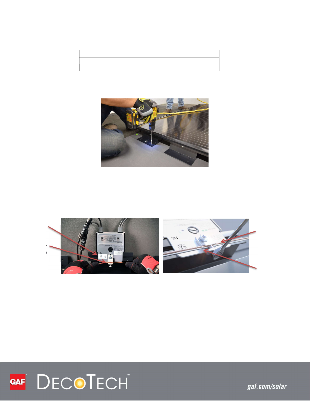
The number of #14 – 1-1/2” (37.5mm) Panel-Tite Roofing Fasteners required per foot depends
on the number of feet and mounting surface. Follow the table below:
Do not overtighten the roofing fasteners.
Figure 41 Attach the Solar Module Assembly to the Deck
Step 4d: Install Grounding... Attach the continuous bare copper ground wire to each WEEB®
Grounding Lug. Include the DynoBond® Ground Jumper where applicable (Figure 42).
Tighten the WEEB® Terminal Screw to 84 inch-pounds (9.5 Nm). Leave some slack in the
copper wire between Solar Module Assemblies for wire management.
WEEB®
Grounding Lug
Bare Copper
Wire
Figure 42 Attaching Ground Wire(s) to WEEB® Grounding Lug
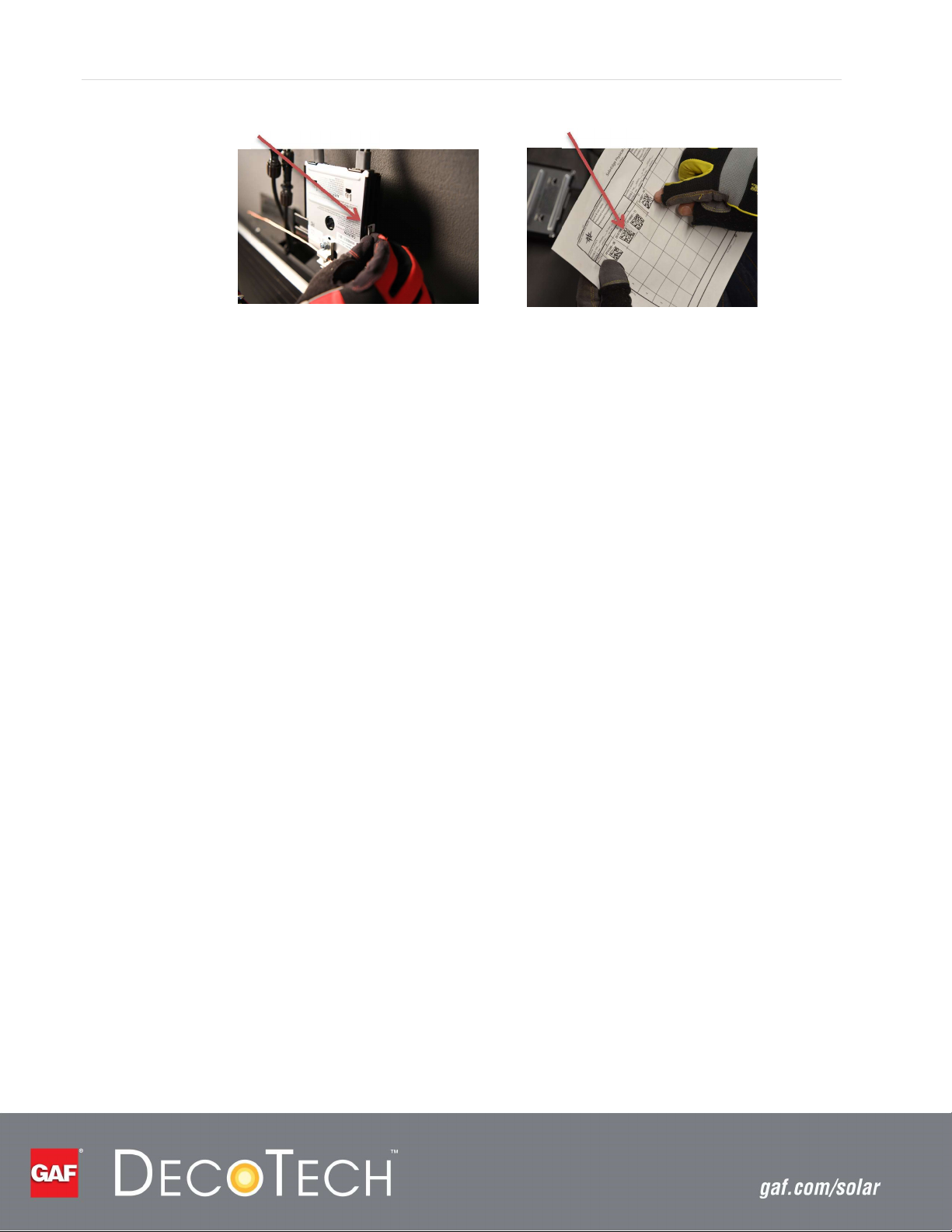
Step 4e: Create the MLPE Map... Create the MLPE map per manufacturer’s instructions (Figure 43).
This map is required for system monitoring and maintenance.
Bare Copper
Wire
DynoBond®
Jumper
Page 40
P a g e | 40
Peel the MLPE Bar Code
Affix the Bar Code to the MLPE Map
Figure 43 Create MLPE Map
Page 41
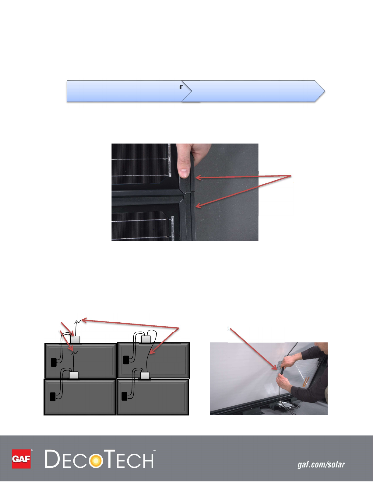
Home Run Wire
Step 5: Install the Remaining Rows of Solar Module Assemblies
Follow the sequence below to complete this step.
P a g e | 41
Step 5a: Install Row of Solar
Module Assemblies
Step 5a: Install Row of Solar Module Assemblies… Repeat the sequence in Step 4 to build each row
from left to right and from bottom to top. Each Solar Module Assembly must align with the
one below it. Align the Solar Module Assemblies from right to left.
Figure 44 Align Solar Module Assemblies
Step 5b: Electrically Connect Row-to-Row... Make the necessary electrical connections from row-to-
row (Figure 45) following the Permit Design Drawings. Ensure proper wire management
including the home run and the ground wire. Ensure that the wires will not come in contact
with the side flashing. Route the home run wire in the spacing between the mounting feet.
The existing cables are long enough to extend from one row to the other.
MLPE
+
Figure 45 Complete Row-To-Row Wiring
Step 5b: Electrically Connect Row to
Row
Ensure that
the Right
Edges of Each
Row Align
Row-to-Row Wiring
Page 42
Step 6: Install Side Flashing
Follow the sequence below to complete this step.
P a g e | 42
Step 6a: Install Starter
Bar Covers
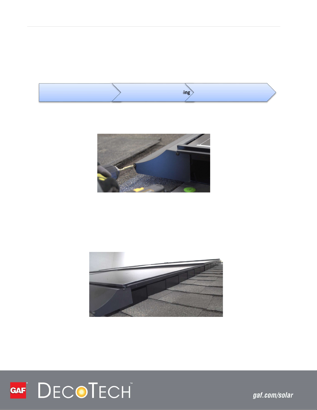
Step 6a: Install Starter Bar Covers… Attach the Left and Right Starter Bar Covers using the provided
screws with a #2 Phillips bit (Figure 46).
Step 6b: Install Step Flashing… The Step Flashing installs as you would with a typical skylight. Slip the
first Step Flashing behind the Starter Bar Cover. Continue installing the Step Flashing and
shingles up to the top of the array. Repeat for each side. See the GAF Steep Slope PRO Field
Guide for installation assistance.
Step 6b: Install Step Flashing Step 6c: Install Counterflashing
Figure 46 Installing Starter Bar Cover
Figure 47 Completed Step Flashing
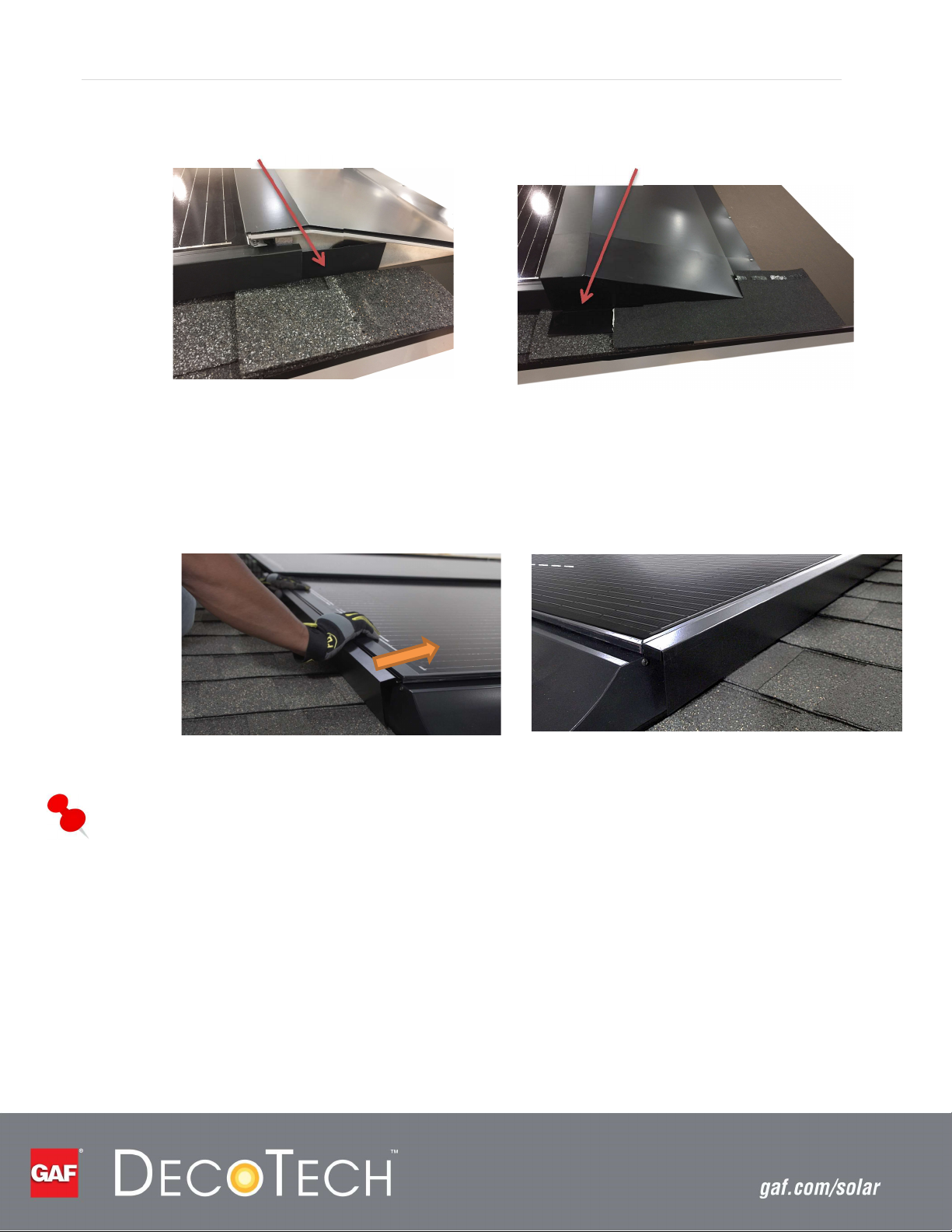
The final Step Flashing should extend past the top of the array. In addition, make sure the
shingle exposure will extend underneath the Top Corner Flashing (installed in next step). See
Figure 48 .
Page 43
P a g e | 43
Top Corner Flashing
Last Step Flashing and Shingle
Figure 48 Step Flashing Overlap
Step 6c: Install Counterflashing… The Counterflashing is installed from the bottom to the top. The
Counterflashing is first mounted on a channel within the module frame and then pressed until
a snap fit is created. Install the Left and Right Counterflashing as shown in Figure 49.
Figure 49 Left and Right Counterflashing
Notes
Remove the plastic film covering from the flashing before installation. Leaving the flashing
exposed to high outdoor temperatures for prolonged periods may make it difficult to remove.
The Left and Right Counterflashing are tapered from bottom (wide) to top (narrow).
Page 44
Top Flashing Frame Insert
Step 7: Install Top Flashing
Follow the sequence below to complete this step.
P a g e | 44
Step 7a: Install the Top Flashing Frame Insert
Step 7d: Install the Grounding Clips
on the Top Flashing
Step 7b: Install the Top
Flashing Supports and
DynoBond™ Jumpers
Step7e: Nail the Top Flashing in
Place
Step 7c: Position the Top
Flashing
Step 7f: Install the Top Corner
Flashing
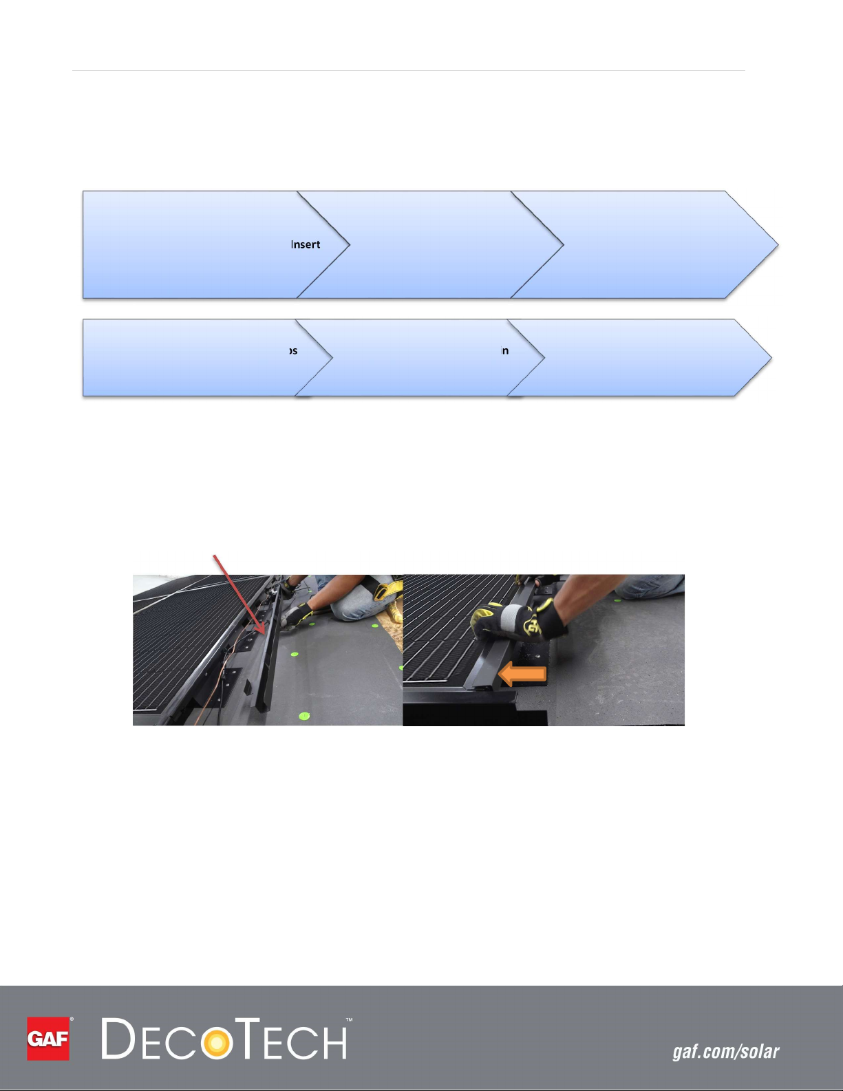
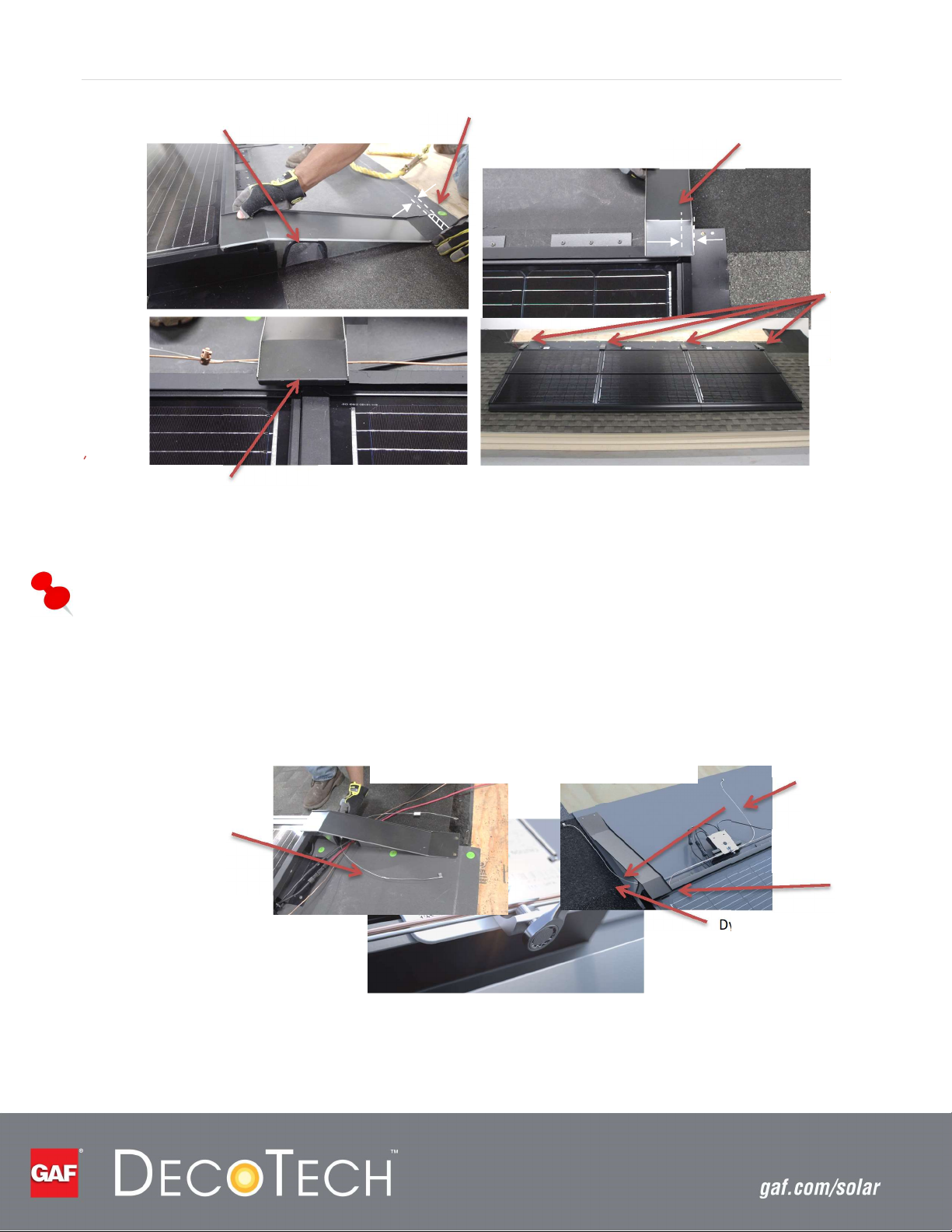
Step 7a: Install the Top Flashing Frame Inserts… The Top Flashing Frame Insert snaps onto the top
edge of the Solar Module Assembly as shown in Figure 50. Verify that every tab is engaged by
pulling back on the Frame Insert. Install one Frame Insert for each Solar Module Assembly
along the top row.
Step 7b: Install the Top Flashing Supports and Position the DynoBond™ Jumpers… Place Top Flashing
Figure 50 Install Top Flashing Frame Insert
Supports at the corners of the array and at every module-to-module joint. It is important to
place the corner Top Flashing Supports 1/4"-1/2" (6-12 mm) from the edge of the
Counterflashing as shown in Figure 51. The remaining Top Flashing Supports must be
centered on the joint between the Solar Module Assemblies. Each support should be fastened
to the deck with two standard roofing nails within 1 inch (25 mm) of the edge. See Figure 51.
Page 45
¼"-½"
1"
38” DynoBond™
Center the Top Flashing
Support on the Overlap
Route Wires Through
This Opening
Nail Only Within 1" (25 mm) from the Edge.
Figure 51 Locations of Top Flashing Supports
P a g e | 45
Position the Corner Top
Flashing Support as Shown
Top Flashing
Supports
within the
Array
Notes
In high snow load areas, additional Top Flashing Supports may be required.
Bend each 38” DynoBond™ Jumper into a U-shape and pass it through the slot in one of the Top Flashing
Supports. The 76” DynoBond™ Jumper is further routed through one of the MLPE Weeb® Grounding Lugs.
See Figure 52. Further details on the system grounding can be found in the grounding Section on Page 17.
Figure 52 Position DynoBond Jumpers
Bare Copper
Grounding Wire
DynoBond™
Grounding Jumper
76” DynoBond™
Top
Flashing
Support
Figure 53 WEEB® Grounding Lug Connection
Attach the 76” DynoBond™ Jumper to the copper grounding wire at a WEEB™ Grounding Lug
(Figure 53). Torque the terminal screw to 85 inch-pounds (9.6 Nm).
Page 46
P a g e | 46
Top Flashing
1
2
3
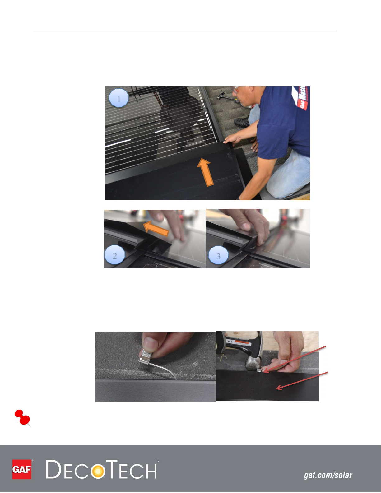
Step 7c: Position the Top Flashing… Position the Top Flashing so that it is aligned with the Solar
Module Assembly. The Top Flashing hooks into the Top Flashing Frame Insert (Figure 54).
Figure 54 Positioning the Top Flashing
Step 7d: Install the Grounding Clips on the Top Flashing... The DynoBond™ Jumper clips are designed
to penetrate the finishing coat on the edge of the Top Flashing. Use a hammer to lightly tap
the clip into place (Figure 55).
Figure 55 Attaching the DynoBond™ Grounding Jumper Clip
Note
The DynoBond™ Grounding Jumper Clips are designed for 1-time use only.
DynoBond™
Grounding Clips
Page 47
P a g e | 47
Top Flashing
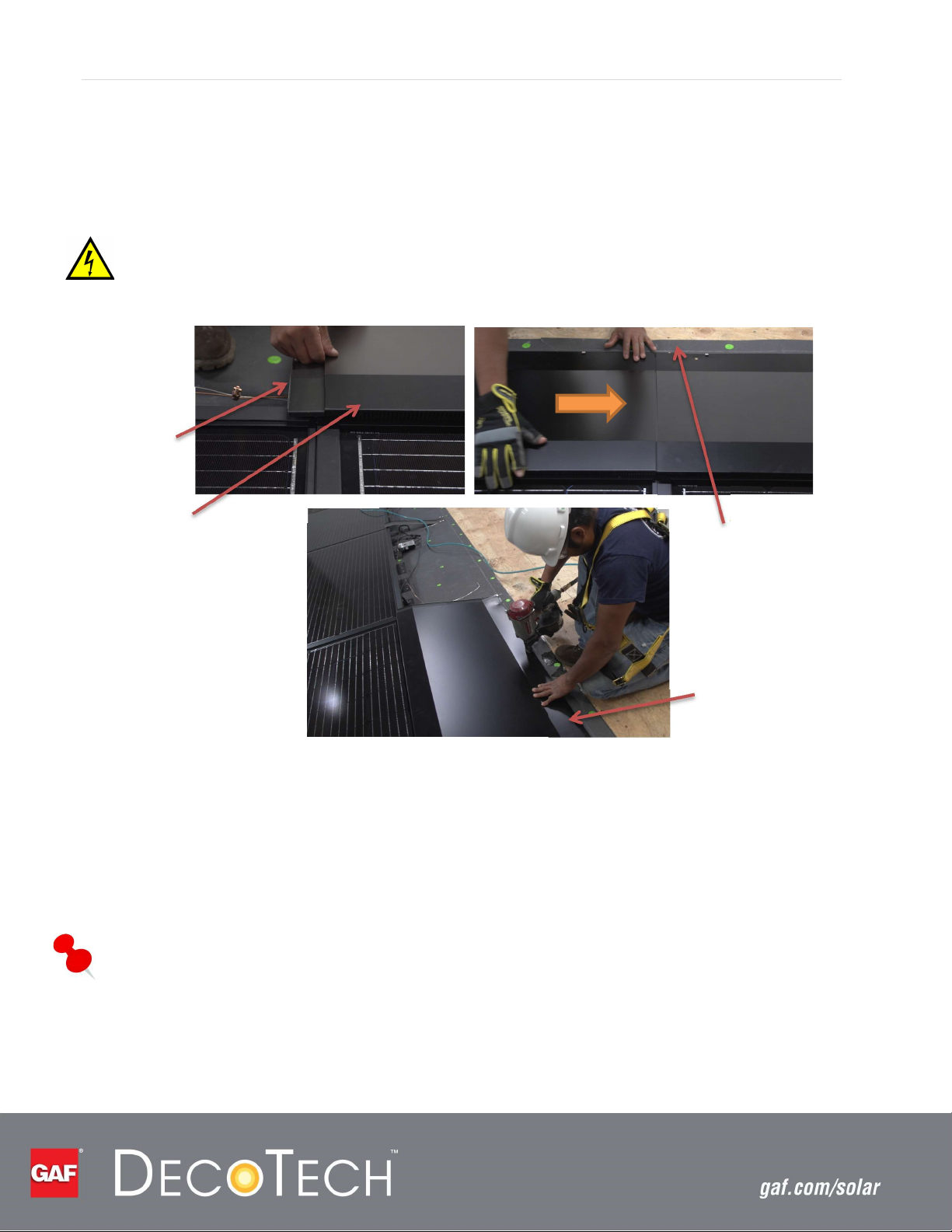
Step 7e: Nail the Top Flashing in Place... Attach the Top Flashing to the deck using a minimum of four
evenly spaced standard roofing nails. Trim excess VersaShield® SOLO™ within ~1 inch of the
Top Flashing. (Figure 56)
WARNING: Before fastening the Top Flashing to the deck, make sure that no electrical cables are
trapped underneath the flat portion.
Top Flashing
Support
Trim the
VersaShield® Solo™
as needed
Figure 60: Position and Nail the Top Flashing in Place
Check for Cables Trapped
Under Top Flashing
Figure 56 Installing the Top Flashing
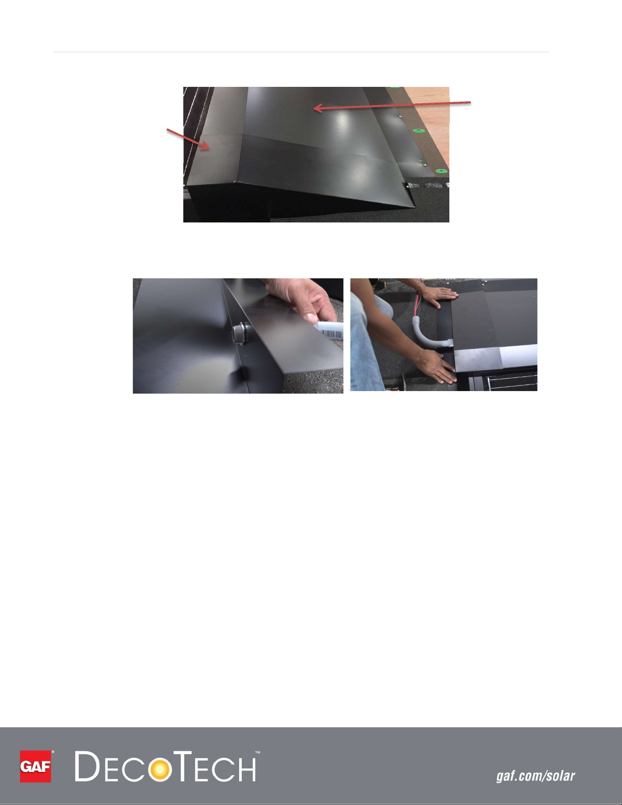
Step 7f: Install the Top Corner Flashing… See the Permit Design Drawings to identify the Top Corner
Flashing (Left or Right) that contains the wire conduit. Attach the prescribed conduit to the
Top Corner Flashing before proceeding. See Figure 58 for a typical example. Install the Top
Corner Flashing over the Top Flashing (Figure 57). Remember to attach the previously
installed DynoBond™ Jumper Clip to each flashing. The Top Corner Flashing should be
fastened with standard roofing nails along the top edge.
NOTE
The nails should be covered by the leak barrier that will be installed in Step 8c.
Page 48
Top Corner Flashing
P a g e | 48
Top Flashing
Figure 57 Install Top Corner Flashing
Figure 58 Top Corner Flashing with Conduit
Page 49
Step 8: Install Top Flashing Underlayment and Complete Shingles
Follow the sequence below to complete this step.
P a g e | 49
Step 8a: Install the
QuickStart® Starter Roll
Over the Top Corner
Flashing
Step 8b: Install
Shingles Over the
Top Corner
Flashing
Step 8c: Install
Leak Barrier Over
the Top Flashing
Step 8d: Install
QuickStart®
Starter Roll Over
the Leak Barrier
Step 8e: Install
Remaining Rows
of Shingles
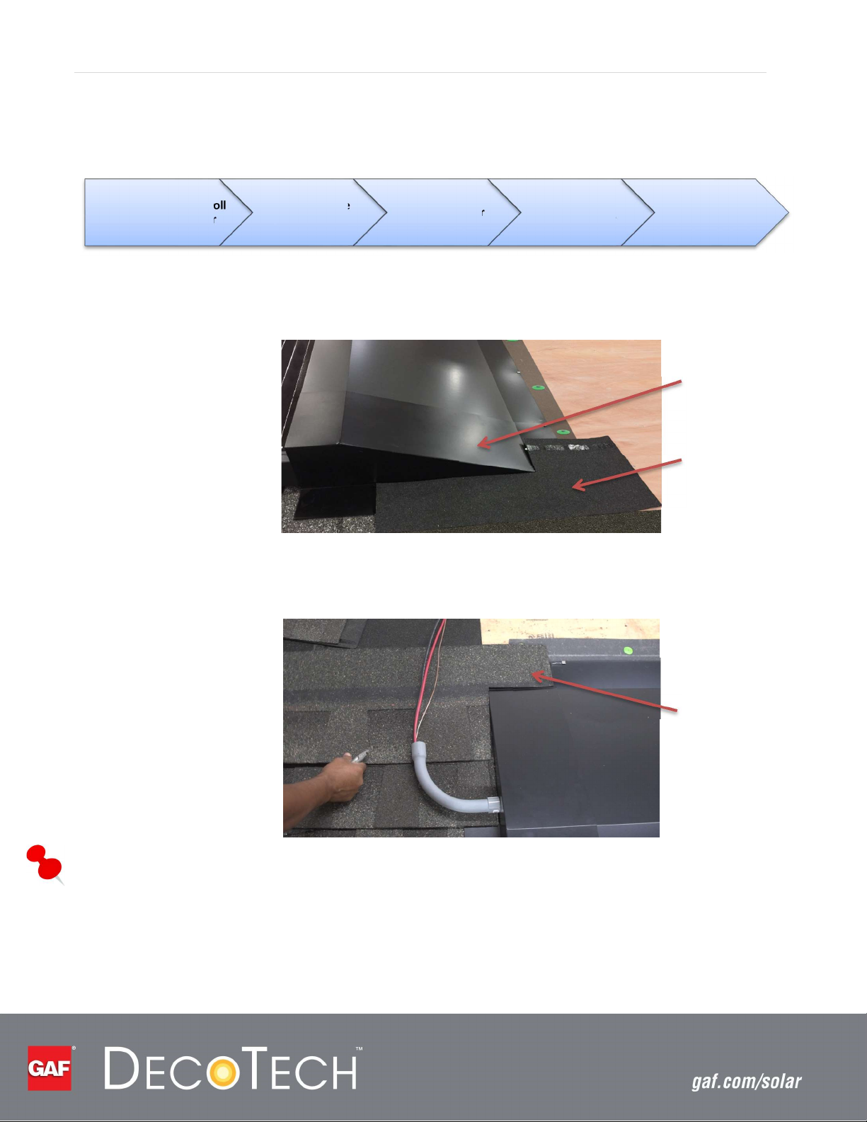
Step 8a: Install the QuickStart® Starter Roll over the Top Corner Flashing... Install a strip of
QuickStart® Peel and Stick Starter Roll over each the Top Corner Flashing as shown in Figure
59. Notch as needed.
Top Corner
Flashing
QuickStart® Peel and
Stick Starter Roll.
Figure 59 Apply QuickStart® Peel and Stick Over the Top Corner Flashing
Step 8b: Install Shingles over the Top Corner Flashing… Install the shingles over the Top Corner
Flashing. Notch as needed as shown in Figure 60.
Notch the Shingle
as needed
Figure 60 Install Shingles over Top Corner Flashing
NOTE
Protect the wires from abrasion on the shingles and other physical damage until the installation is
complete.
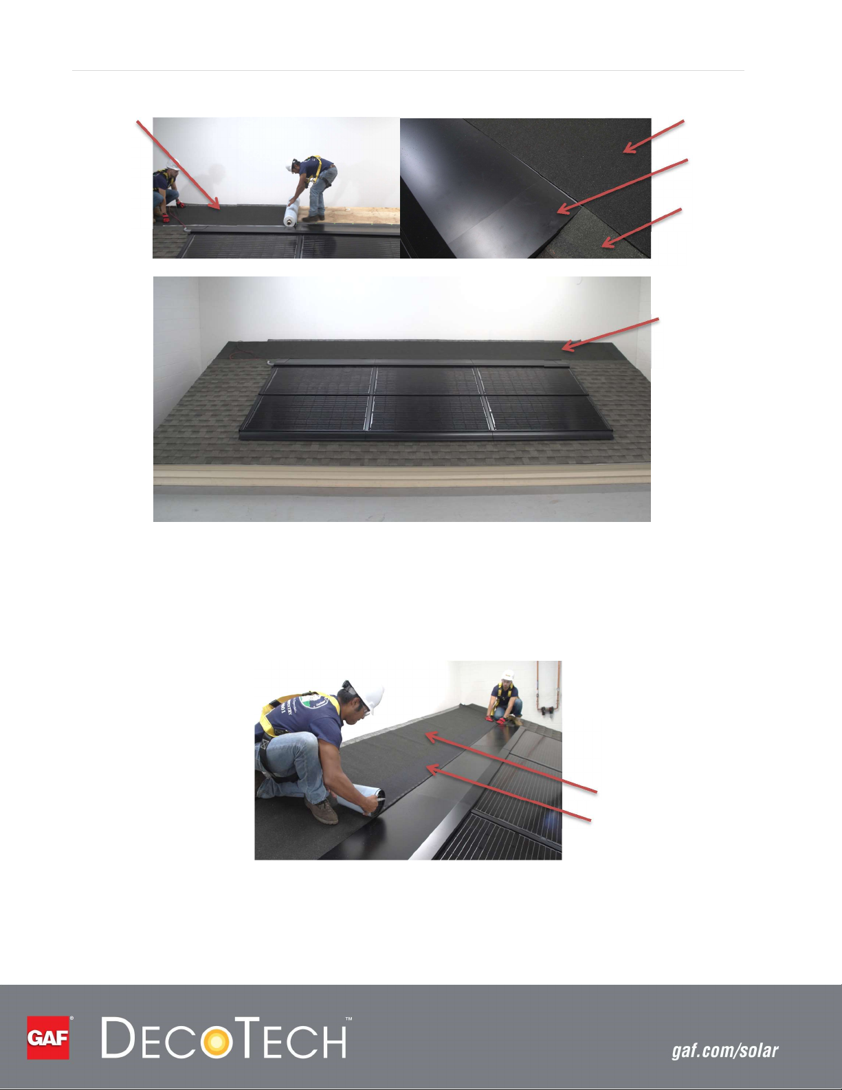
Step 8c: Install the Leak Barrier over the Top Flashing… Install StormGuard® Leak Barrier over the
nailing area of the Top Flashing. The Leak Barrier should cover the headlap of the adjacent
row of shingles and extend past the array approximately 3 feet (914 mm) (Figure 61).
Page 50
P a g e | 50
Leak Barrier
Shingle
Leak Barrier
Leak Barrier
Leak Barrier
Top Corner
Flashing
Figure 61 Install leak Barrier over Top Flashing and Shingles
Step 8d: Install QuickStart® Peel and Stick Starter Roll over the Leak Barrier... The QuickStart® Peel
and Stick Starter Roll is the starter course for the row of shingles that will be installed above
the array. The QuickStart® Peel and Stick Starter Roll is should extend to the edges of the
Leak Barrier (Figure 62).
QuickStart® Peel
and Stick Starter
Roll
Figure 62 Install QuickStart Starter Roll over the Leak Barrier
Page 51
P a g e | 51
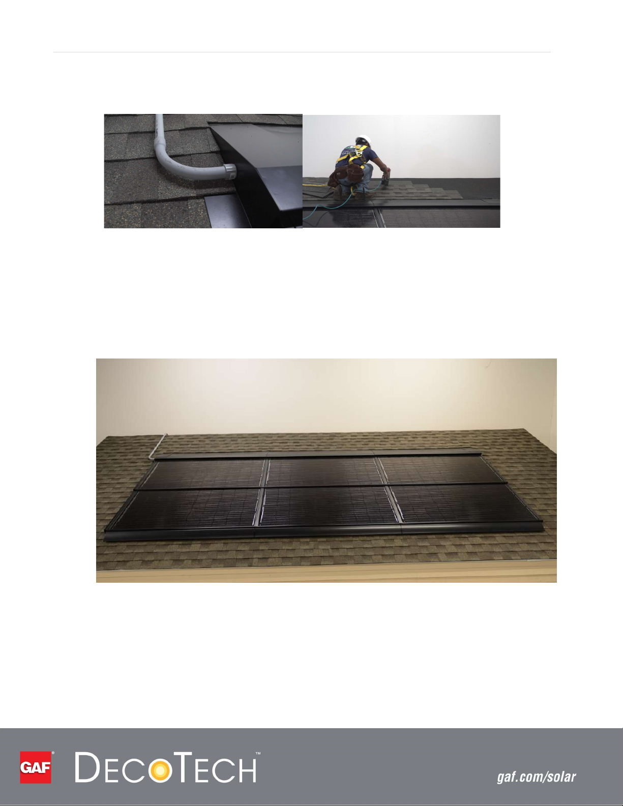
Step 8e: Install Remaining Rows of Shingles… Continue installing shingles up to the roof peak
following roofing best practices (Figure 63).
Figure 63 Complete Installing Shingles
Completed GAF Solar Energy System
The following figure shows the completed GAF Solar Energy System.
Figure 64 Completed GAF Solar Energy System
Page 52
P a g e | 52
Box
Module Assembly
AC Microinverter
Cap
SECTION 5 — WIRE MANAGEMENT
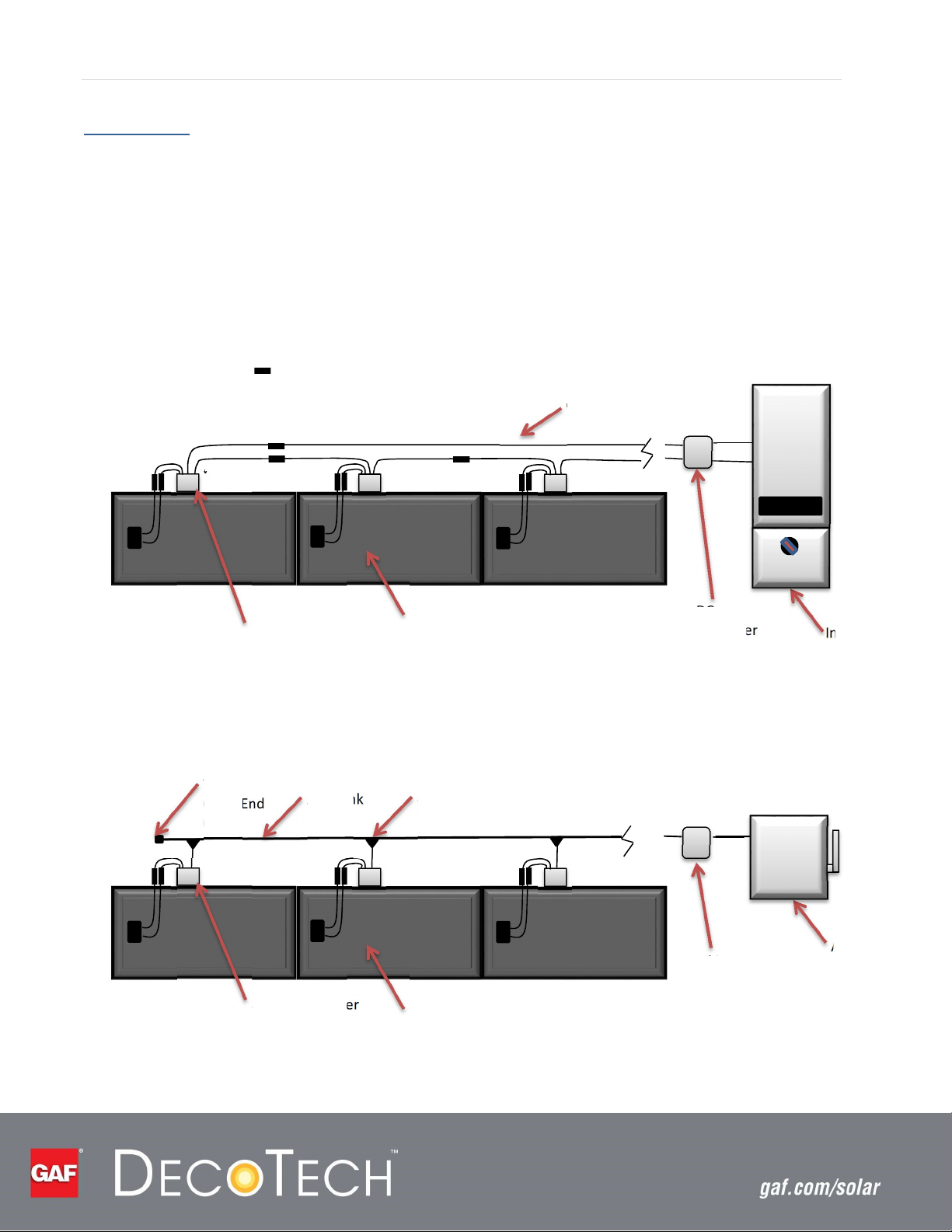
An MLPE (AC Microinverter or DC Power Optimizer) is integrated into the GAF Module Assembly.
Following are typical examples of how the MLPES are wired in the field. Refer to the Permit Design
Drawings for exact details for your installation.
DC Optimizer
The typical schematic with a DC optimizer is shown below:
= MC-4 Type Connector
Home Run Wire
V+
V-
V+
Figure 65 Typical DC Optimizer Wiring
V-
Module Assembly DC Optimizer
V+
V-
DC
Combiner
Inverter
with DC
Disconnect
AC Microinverter
The typical schematic with an AC Microinverter is shown below:
Trunk
Cable End
AC Trunk
Cable
Figure 66 Typical AC Microinverter Wiring
AC
Connector
AC Combiner
Box
AC
Disconnect
Page 53
P a g e | 53
Detail B
Detail A
Detail B
Detail A
Flashing)
MLPE
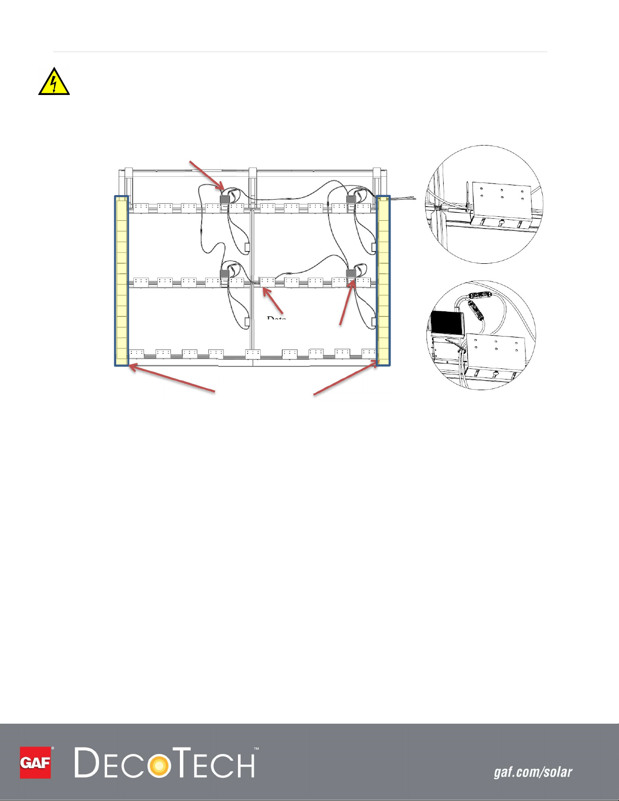
The installing contractor must ensure that none of the wiring comes in contact with any of the Side
Flashing. Use wire ties wherever necessary and route the wires through the gaps between the
Adjustable Feet for proper wire management (Figure 67). The minimum clearance between the
wires and Side Flashing is 2 inches (51 mm). Always obey the cables’ minimum bend radius.
Side Flashing (Step
Flashing & Counter
Figure 67 Typical Wire Management
Page 54

P a g e | 54
SECTION 6 — GAF SOLAR ENERGY SYSTEM MANINENANCE
The GAF Solar Energy System has no user-serviceable parts and requires no routine maintenance.
However, periodic re-inspection of the PV installation for loose components, loose fasteners, and any
corrosion of components is required. If any issues are found, the affected components must be
immediately replaced by the installer.
Do NOT attempt to dismantle the equipment or make any internal repairs. Any attempt to open the
equipment could compromise the integrity of the system and void the warranty on the system.
Do NOT attempt to clean soiled solar module assemblies. GAF Solar Module Assemblies are naturally
cleaned by seasonal rains. In the unlikely event that cleaning is required, contact your installer.
Direct all inquiries to GAF Solar Technical Support at 1-800-ROOF-411.
For more information on GAF solar products and services for solar applications, visit gaf.com/solar.
Page 55
SECTION 7 — APPENDIX
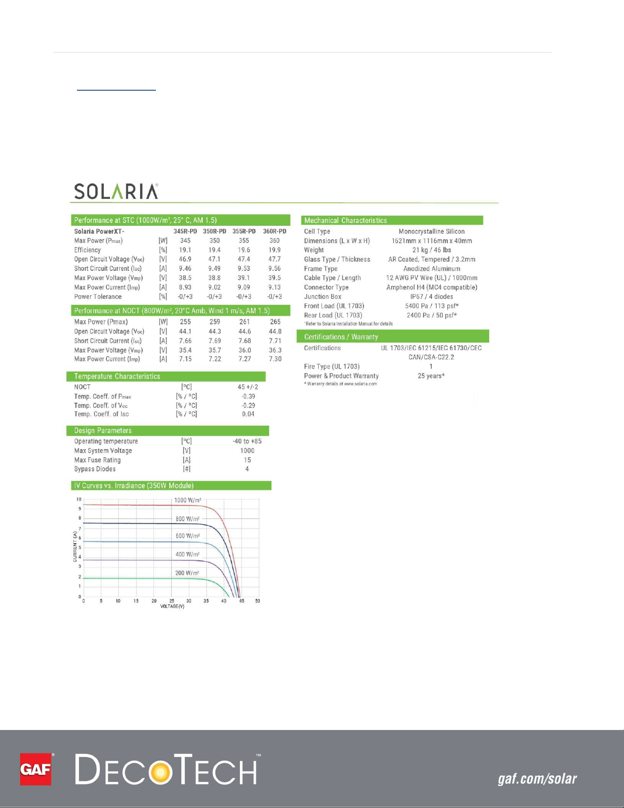
GAF Solar Module Technical Data
Table 4 Solaria Laminate Specifications
P a g e | 55
Page 56
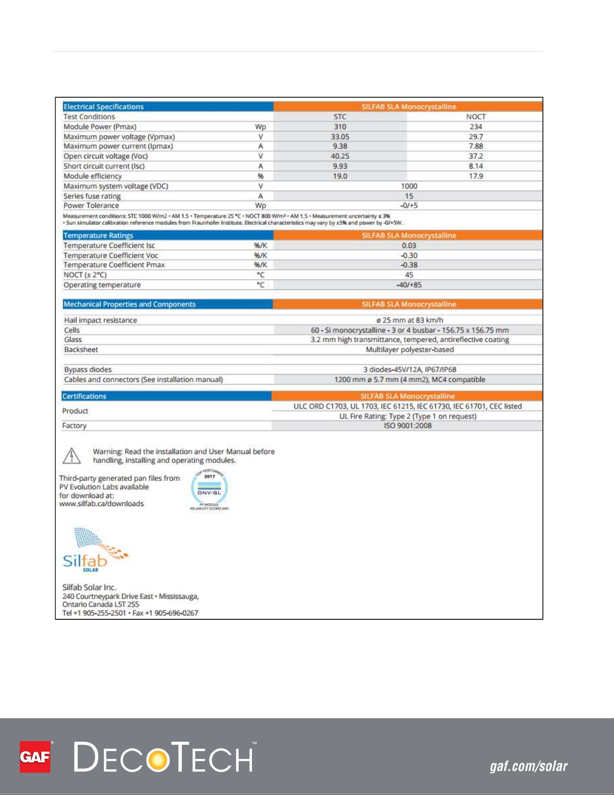
Table 5 Silfab Laminate Specifications
P a g e | 56
Page 57
Length
65.3 inches
(1,
659 mm)
66.5
inches
(1,689
mm)
To achieve a Class A fire rating, the solar array must be installed with one ply of
StormGuard® Film
-
Surfaced
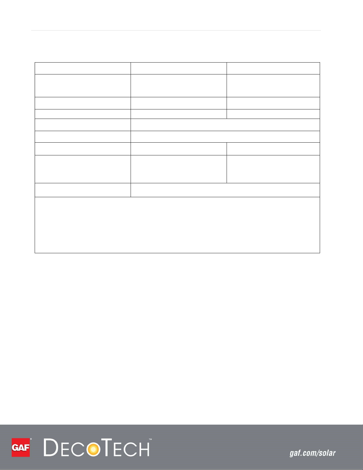
Table 6 Mechanical Properties of the GAF Solar Energy System
With Solaria Laminates With Silfab Laminates
P a g e | 57
Weight (Framed Module + 5
Mounting Feet + MLPE Bracket)
55 lb. (53 kg) 51 lb. (23 kg)
Width 45.0 inches (1,143 mm) 40 inches (1,016 mm)
Depth, Front 1.67 inches (42 mm)
Depth, Back Adjustable
Frame Black anodized aluminum Black powder-coated aluminum
Mechanical Loading
50 lb./ft2 (244 kg/m2) positive
design load
40 lb./ft2 (195 kg/m2) negative
design load
50 lb./ft2 (244 kg/m2) positive
design load
50 lb./ft2 (244 kg/m2) negative
design load
Fire Rating Class A per UL 2703
Leak Barrier followed by one ply of VersaShield® SOLO™ Fire-Resistant Slip Sheet over minimum 15/32
inches (11.9 mm) thick plywood or 7/16 inches (11.1 mm) OSB roof deck. Please refer to Underwriters
Laboratories Certifications Directory for actual assemblies.
Page 58

P a g e | 58
GAF Solar Energy System Codes and Standards
The GAF Solar Energy System includes the GAF Solar Module Assembly, the underlayment system, and flashing
components. Certifications are listed below.
PV Laminate (Frameless)
The PV laminates are certified to UL 1703.
GAF Solar Module Assembly and Flashing
The GAF Solar Module Assembly and Flashing are certified to UL 2703.
The certification includes the MLPE Mounting Bracket and Grounding Lug.
GAF Solar Array
The GAF Solar Array was tested to comply with the following roofing standards:
UL 1897 Uplift Tests for Roof-Covering Systems
TAS 100 Test Procedure for Wind and Wind-Driven Rain Resistance of Discontinuous Roof Systems
Fire Rating
The GAF Solar Module Assembly, in combination with the underlayment system, is classified as a Class A fire
rated system per UL 2703.
Underlayment System
StormGuard® Film-Surfaced Leak Barrier is tested and certified to comply with the following standards:
Meets or exceeds ASTM D1970 – Standard Specification for Self-Adhering Polymer Modified
Bituminous Sheet Materials
Used as Steep Roofing Underlayment for Ice Dam Protection
ICC-ES Evaluation Report (ESR-1322)
Miami-Dade County Product Control approved (18-0119.15)
State of Florida approved (FL10626)
UL Classified
VersaShield® SOLO™ Fire-Resistant Slip Sheet is tested and certified to comply with the following standards:
UL Classified
Miami-Dade County Product Control approved (16-1216.02)
QuickStart® Peel and Stick Starter Roll is tested and certified to comply with the following standards:
Meets or exceeds the physical requirements of ASTM D1970
State of Florida approved (FL10124)
Note
Refer to UL Online Certification Directory for actual assemblies.
Follow all instructions in this document to assure the system is installed as certified.
Page 59
P a g e | 59
Alternate Solar System Configurations
The GAF Solar Array can be assembled in non-rectangular configurations. This section describes the unique
steps required for these configurations.
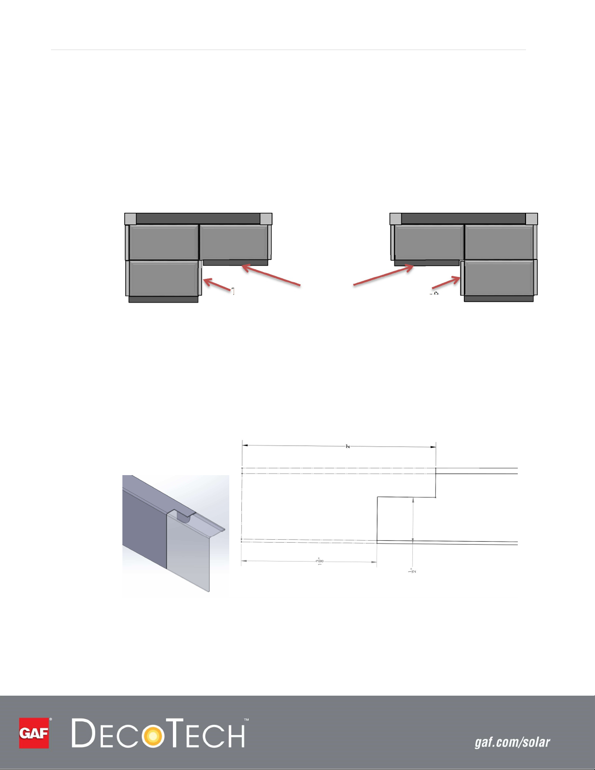
Type B – Left Bottom Inside Corner OR Right Bottom Inside Corner Configuration
With this configuration, the Counterflashing must be field-modified to accommodate the adjoining Starter
Bar. The other flashing components are used as is.
Trimmed Right
Counterflashing
Figure 68 Configuration Type B
Starter Bar
Trimmed Left
Counterflashing
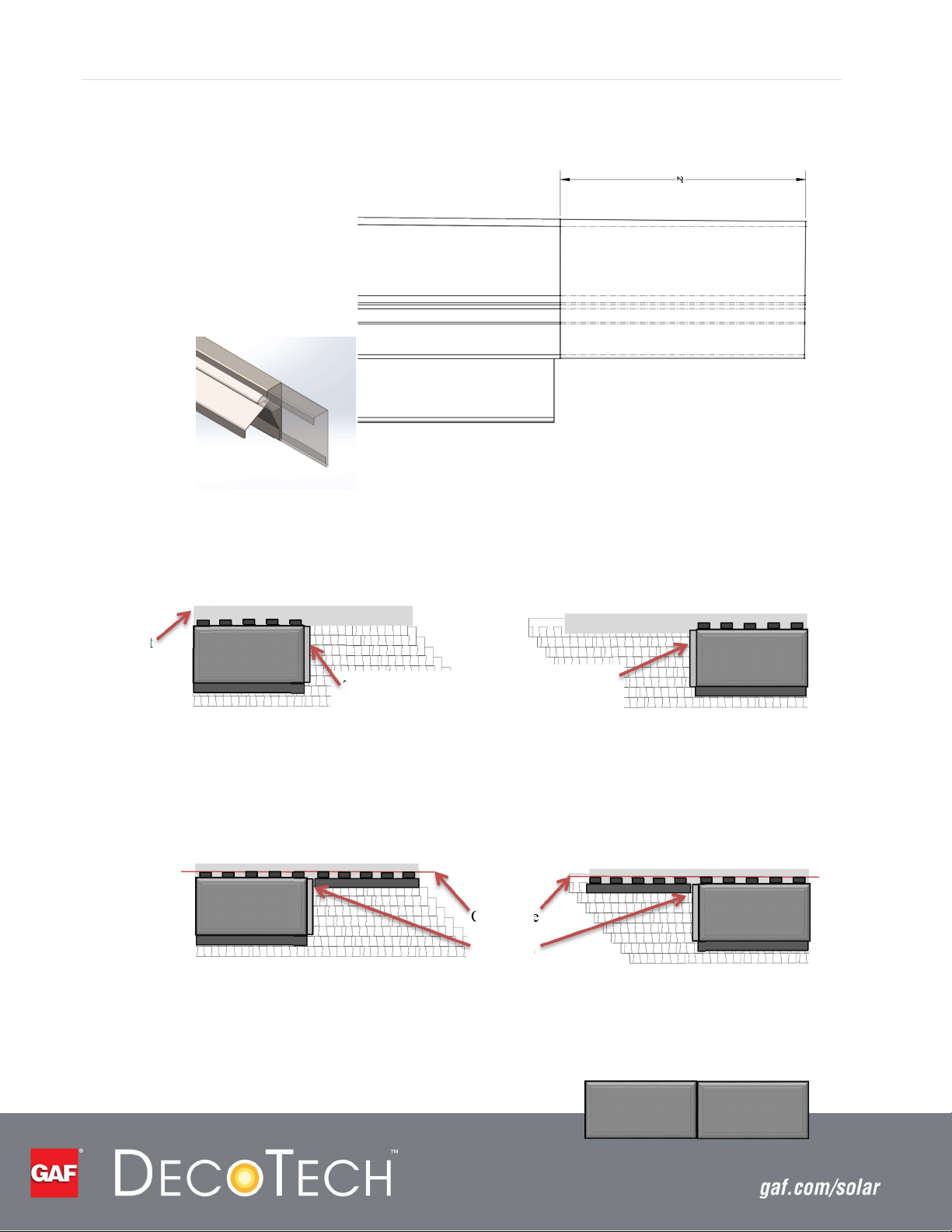
Step 1: Trim the Right Counterflashing as shown in Figure 69 or the Left Counterflashing as shown in
Figure 70. The Right Counterflashing requires a compound cut while the Left Counterflashing
requires a single straight cut.
Figure 69 Trimming Right Counterflashing
Page 60
P a g e | 60
Figure 70 Trimming Left Counterflashing
Step 2: Install the shingles, underlayment, Starter Bar, Solar Module Assembly, Step Flashing, and the
field-trimmed Counterflashing as shown in Figure 71.
Underlayment
Trimmed Right
Counterflashing
`
Figure 71 Configuration B - Step 2
Trimmed Left
Counterflashing
Step 3: Snap a chalk line to align the Adjustable Feet to the adjacent Starter Bar as shown in Figure
72. Leave a small (approximately 1/8 inch) gap between the Inside Counterflashing and the
Starter Bar. Attach the Starter Bar to the deck.
Chalk Line
Figure 72 Configuration B - Step 3
1/8” Gap
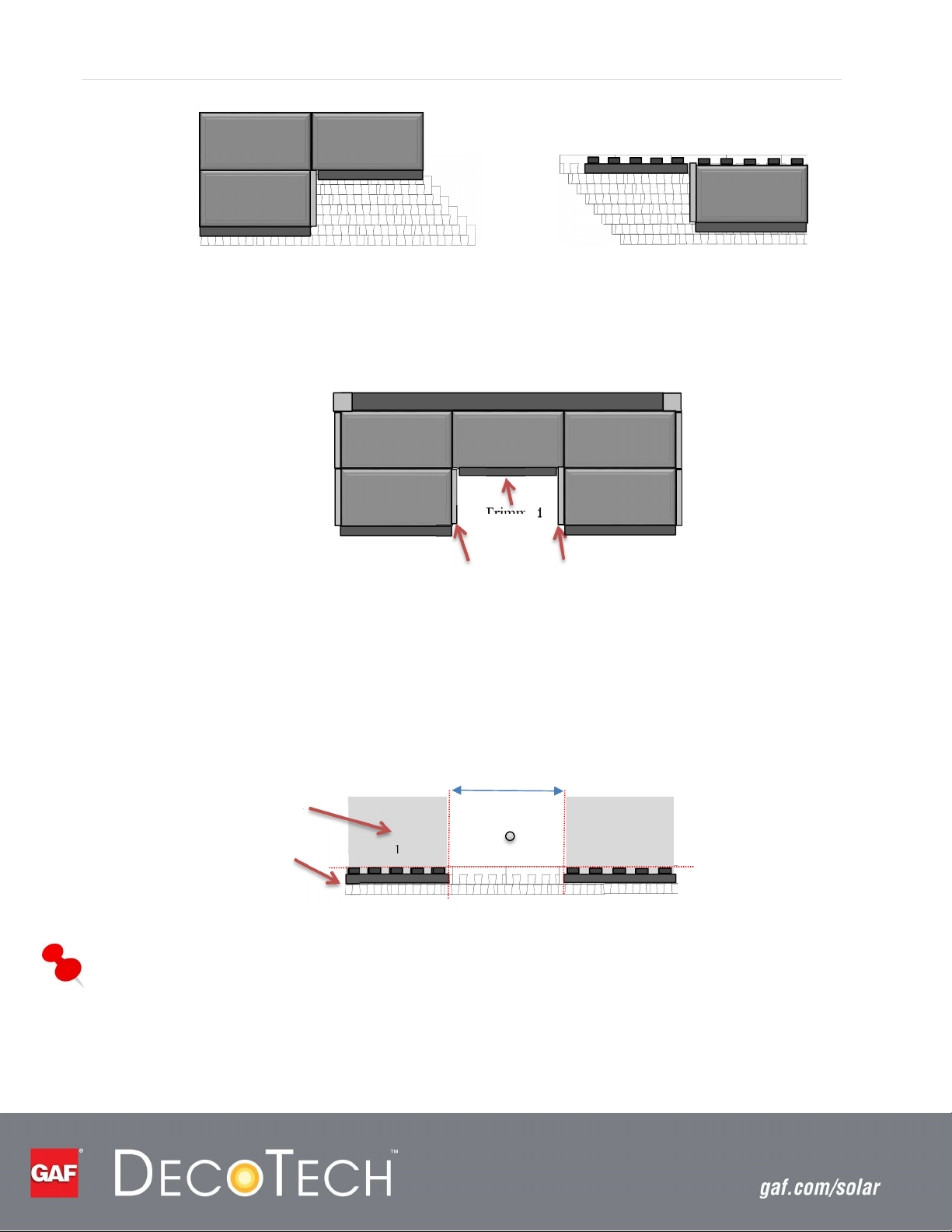
Step 4: Align and attach Solar Module Assemblies 2 and 3 as shown below. Complete the array following the
standard installation procedures.
Page 61
P a g e | 61
2
1
3
Figure 73 Configuration B - Step 4
3 2
1
Type C – Left Bottom inside Corner AND Right Bottom inside Corner Configuration
With this configuration, the Left and Right Counterflashing as well as the Starter Bar must be field-modified
to ensure a proper fit. The other flashing components remain the same.
1 2
Trimmed Right
Counterflashing
Figure 74 Configuration Type C
Trimmed
Starter
Bar
Trimmed Left
Counterflashing
Step 1: Following the standard installation procedures, install the shingles up to the location of
Starter Bars 1 and 2 as well as the adjacent underlayment. Locate and attach Starter Bar 1.
Next, align and attach Starter Bar 2 using the appropriate spacing per the Permit Design
Drawings.
Underlayment
D x No. of Module Assemblies
Shingle to Here
1
Obstruction
2
Figure 75 Configuration C - Step 1
Note
Accurate placement of Starter Bar 2 is critical to the assembly of the rest of the array.
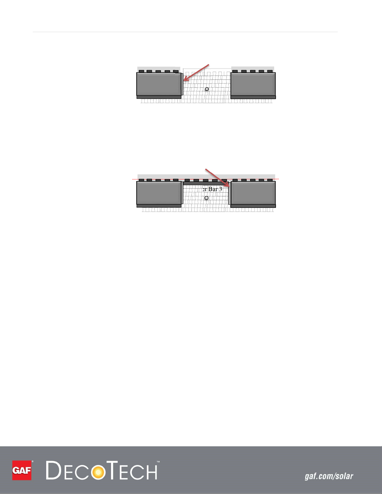
Step 2: Attach the Solar Module Assemblies as shown in Figure 76. Continue to step flash and shingle
along the sides of the Solar Module Assemblies. Trim the Right Counterflashing as shown in
Figure 69. Attach the Right Counterflashing to Solar Module Assembly 1.
Page 62
P a g e | 62
2
1
Figure 76 Configuration C - Step 2
Step 3: Install the underlayment. Field modify Starter Bar 3 by removing 1 inch from both sides. Snap
a chalk line to align and attach the shortened Starter Bar 3 as shown in Figure 77. Trim the
Left Counterflashing as shown in Figure 70. Install the Left Counterflashing to Solar Module
Assembly 2. Complete the array following the standard installation procedures.
1
Figure 77 Configuration C - Step 3
Trimmed Right Counterflashing
Trimmed Left Counterflashing
Starter Bar 3
2
Page 63
P a g e | 63
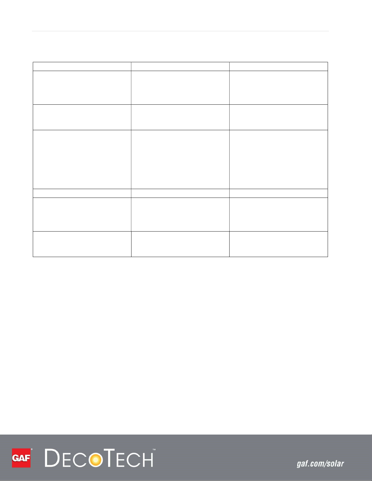
Version Control
Version Number
1.0.0
1.0.1
1.1.0
2.0
3.0
3.1
Table 8: Version Control Table
Date
Notes
5/2017 Added info on Alignment Pins,
Version Control Table,
Custom Step Flashing, and lab
tested design load values.
7/2017
Added alternate array
configurations and 2 wire
WEEB lug.
11/2017
Added Silfab laminate,
adjustable feet, updated SKU
numbers and right
counterflashing install, wire
management techniques and
grounding methods for the
adjustable feet.
03/2018
04/2019
Updated product name,
Edited for clarity
updated SKUs, added Solaria
laminate, removed SolarWorld
laminate
08/2019
Added three-feet mounting
option, more Dynobond
grounding options
 Loading...