

G4S Technology S870 User Manual
Installation and User Instructions for S870-EX Keypad Readers
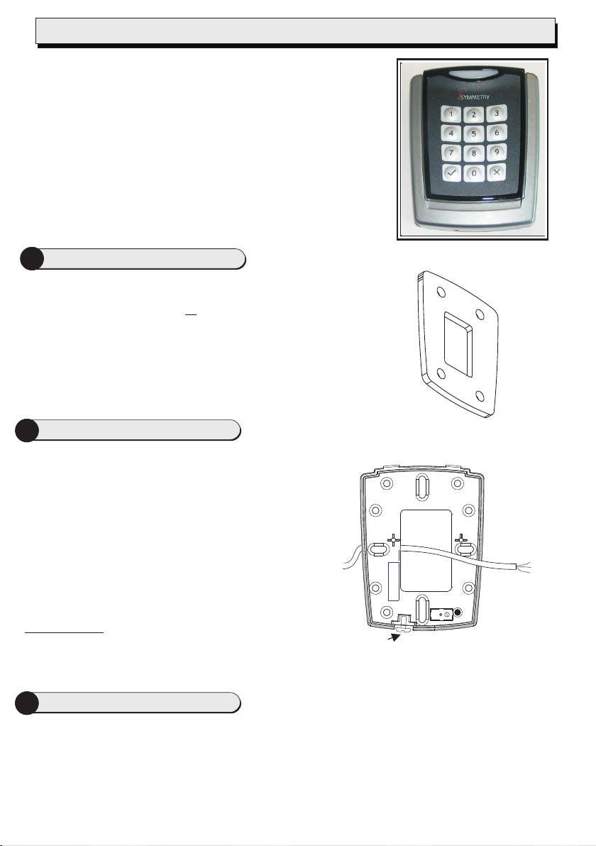
The S870
reading HID format card, with LED’s and keypad. The reader can
be set to use Wiegand or
For additional information regarding the installation,
configuration and proper use of this product:
SMS Software User Guide, P/N 9600-0429 Issue 7.0.4 or later,
M2150 Design Guide, P/N 9600-0420 Issue Issue 1.6.4 or
later.
1
When mounting outside, the gasket kit must be fitted:
a) Remove the backplate from the reader after screwing
b) Position the gasket between the back plate and the
2
Mount the backplate using countersunk headed screws
adjacent to the opening edge of the door.
If fixing hole ’A’ is used then the breakout must be removed
and the screw must not protrude.
Feed the cable from the controller through the backplate.
If the wall tamper function is to be used then the small hole in
breakout ‘B’ may be used to mark the position of the wall
screw before the breakout is removed. An appropriate wall
screw should then be adjusted in height to protrude through
the hole to activate the tamper lever.
The front cover is secured to the backplate by
UNSCREWING the securing screw ‘C’ via the small hole
in the enclosure so that the screw head locates in the
counterbored hole on the inside of the enclosure.
The screw should not be removed from the backplate.
is a 125kHz proximity card reader that is capable of
®
20mA current loop communications.
Fit The Weather Proofing Kit
the securing screw ‘C’ fully IN.
mounting surface.
Note: For UL listed applications, use only
manufacturer provided gasket, P/N 87X-GASKET.
Mount the Backplate
You should find
that the backplate
has holes for
connection to most
standard electrical
backboxes.
B
A
C
3
Note: (For UL Installations only)
1). Consult local AHJ (Authority Having Jurisdiction) when installing access control readers and locking
2). The use of Fail Closed / secure configuration shall be determined by local building codes and the
3). Wiring methods shall be in accordance with NEC (National Electrical Code) ANSI/NFPA 70.
4). All Interconnected devices must be UL listed.
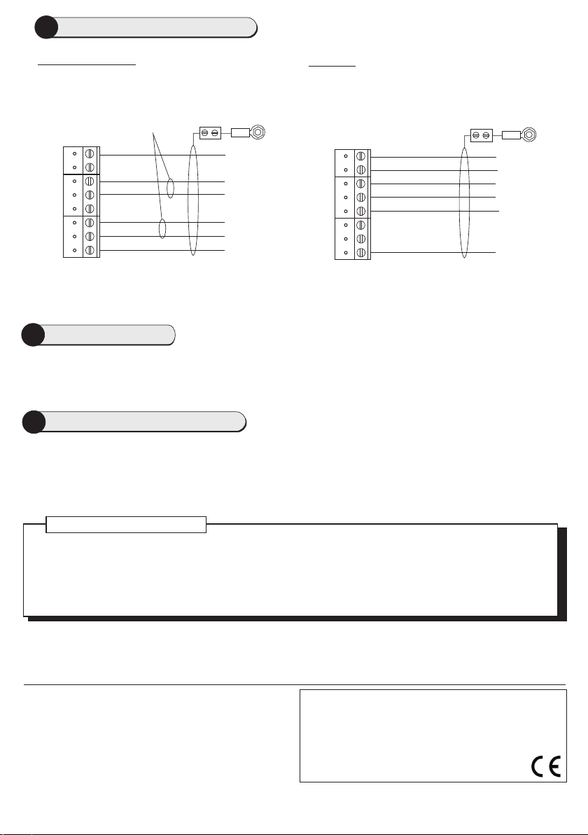
Reader Connections
mechanisms to any portal in an egress path.
local AHJ.
Reader Connections contd.
4
20mA current loop
Twisted pairs (use Belden
9503) cable or other UL
Listed style 2464 (DUZX)
cable.
0V
TX+
TX-
RX+
RX-
+V
Reader
TB1
Connect shield at
controller end
only.
0V
RX+
RX-
TX+
TX12V
Controller
Wiegand
Multi conductor (Use
Belden 9537) or other
UL Listed style 2464
(DUZX) cable.
0V
RED
GRN
0
1
+V
Reader
TB1
Connect shield
at controller end
only.
0V
Red
Green
Data 0
Data 1
12V
Controller
Note: Use SW1 switch2 to select the communications mode (See Step 5).
Reader Links
5
Set SW1 switch2 (COM) to W for Wiegand communications, or C for 20mA current loop communications. Set
SW1 switch1 (USER F/B - Keypad audio feedback) to 1 for sound on, or 0 for sound off.
6
Present the card face-on to the reader until you hear a "bleep". Cards can be presented in rapid succession;
Using the Reader
there is no need, for example, to wait for "GREEN LED’s" to disappear before presenting another.
If the reader has been enabled for user-code mode at the controller, you can gain access by pressing the O key,
entering your card number, then pressing the P key.
LED Status Indicator
GREEN – The lock is released and you may open the door.
RED – You do not have access rights to gain entry, or the reader did not read your card properly (in this case,
present it again).
YELLOW – Enter your PIN. If you make a mistake, the RED LED’s are momentarily displayed, followed by
YELLOW LED’s, to prompt you to try again.
9600-0605. Installation and User Instructions for S870-EX Keypad
Readers, Issue 1.0x2 26th June 2012. G4S Technology, 2012.
FCC Notice: This device complies with Part 15 of the FCC Rules.
Operation is subject to the following two conditions: (1) This device may
not cause harmful interference, and (2) this device must accept any
interference received, including interference that may cause undesired
operation.
Any unauthorized modification to this device may void the authority of
the user to operate it. All trademarks acknowledged.
©
Specifications
Input voltage: 9-14Vdc.
Input current: 120mA @ nom. 12Vdc.
Operating temperature: -40 to 158°F (-40 to 70°C)
Operating humidity: 15 to 90%, non-condensing.
Maximum read range: 4" (100mm).
Approvals: EN300330, EN301489
 Loading...