

G4S Technology S844 User Manual
Installation and User Instructions for S844 Readers
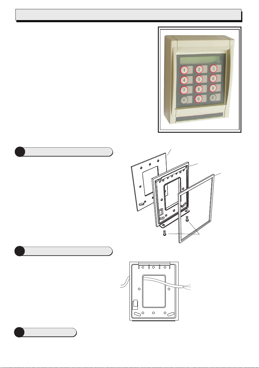
The S844 is a
keypad. The reader can be set to use Wiegand or
current loop seudo-random communications.
The S844 is able to read Personal Identity Verification (PIV II)
type A and B, Philips MIFARE and Philips MIFARE DESfire
smart cards. For Philips MIFARE and Philips MIFARE DESfire
cards, the S844 supports the use of unencoded cards (where
only the unique card serial number is read), or cards encoded
with a card number. Several encoding formats are supported.
The reader can simultaneously support two different card
types/formats (e.g. non-encoded MIFARE and smartMAXencoded MIFARE DESfire, or non-encoded MIFARE and
smartMAX-encoded MIFARE). The reader is automatically
configured to accept the first two card types/formats presented
after power is applied.
Note: For PIV II compliance, Wiegand communications should
be used.
Fit the Weatherproofing Kit
1
When mounting outside, the two-part gasket kit
must be fitted:
a) Remove the backplate from the reader by
releasing the two securing screws.
b) Remove the cutouts and backing paper
from the two gaskets, then stick them to the
backplate as shown.
The optional heater kit maintains the reader at
the correct temperature when mounted outside.
With the backplate off, remove the backing paper
from the two elements, then stick them to the
inner sides of the reader. The heaters must be
connected to a 24V AC supply (min 25VA).
contactless smart-card reader, with LCD and
20mA
p
Outer gasket
Backplate
Inner
gasket
Backplate
securing screws
2
With the backplate off (see above), mount
the backplate adjacent to the opening edge
of the door and at a convenient height. Feed
the required cables through the backplate:
!The cable from the controller.
!The cable from the heater, if used (must
!A cable from a Remote Interface Module
3
Set LK1 (USER FB) to 1 for sound on, or 0 for sound off. If a jumper is provided for LK2 (TEST), park it
across one pin only. Set LK3 (COMMS) across the center and WGD pin for Wiegand communications, or
across the center and C/L pin for 20mA current loop communications.
Mount the Backplate
be a separate cable).
(RIM), if used. A RIM can reduce cable
lengths to door furniture.
Reader Links
You should find that the
backplate has holes for
connection to most
standard electrical
backboxes.
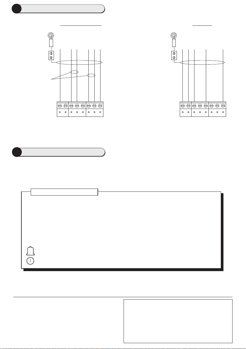
4
Reader Connections
Note: Use LK3 to select
the communications
mode (see step 3).
12V
The I/O terminal is for
connection to a RIM
(see the RIM
Instructions).
+V
Connect shield
at controller end
only.
Use Belden
9537 cable
Reader
Wiegand
Ground
Data 0
0
0V
Controller
Green
GRN
Data 1
1
12V
+V
Connect shield
at controller end
only.
Twisted pairs (use
Belden 9503 cable)
Reader
20mA current loop
Controller
0V
RX+
RX-
TX+
TX-
TX+
TX-
I/0
RX-
RX+
0V
Note: The FERRITE must be fitted!
Slide the ferrite sleeve onto cable before wiring terminal block. Ferrite to be placed 50mm (2") up cable
and held in place with cable ties.
5
Present the card face-on to the reader until you hear a "bleep". Cards can be presented in rapid succession;
Using the Reader
there is no need, for example, to wait for "UNLOCKED" to disappear before presenting another.
If the reader has been enabled for user-code mode at the controller, you can gain access by pressing the #
key, entering your card number, then pressing the * key.
About the Reader Messages
READY –
The reader is waiting for a valid card to be presented.
UNLOCKED – The lock is released and you may open the door.
ACCESS DENIED & LOCKED – You do not have access rights to gain entry, or the reader
did not read your card properly (in this case, present it again).
ENTER PIN – Enter your PIN. If you make a mistake, the message INCORRECT PIN is
momentarily displayed, followed by ENTER PIN, to prompt you to try again.
CARD PIN AND # – Enter the DESfire card PIN, then press # if the PIN is less than 8 digits.
(Flashing or steady) – These auxiliary indicators can be configured to operate in
conjunction with conditional commands.
}
A Setup menu can be displayed by pressing the * and # keys simultaneously while power is applied. You can
use the menu to change the contrast and language used for the LCD (default English). At the prompts, press
* for No and # for Yes.
9600-0452. Installation and User Instructions for S844 Readers,
Issue 2.0.1 8th December 2009. G4S Technology, 2009.
FCC Notice: This device complies with Part 15 of the FCC Rules.
Operation is subject to the following two conditions: (1) This device
may not cause harmful interference, and (2) this device must accept
any interference received, including interference that may cause
undesired operation.
Any unauthorized modification to this device may void the authority of
the user to operate it. All trademarks acknowledged.
©
Specifications
Input voltage: 10.2-14Vdc.
Input current (excl. heater): 180mA @ nom. 12Vdc.
Operating temperature: -4 to 158 F (-20 to 70 C)
° °
without heater.
Operating humidity: 15 to 90%, non-condensing.
Maximum read range: 3/4" (20mm).
Approvals: EN50133, R&TTE, IP656.
 Loading...