

Page 1
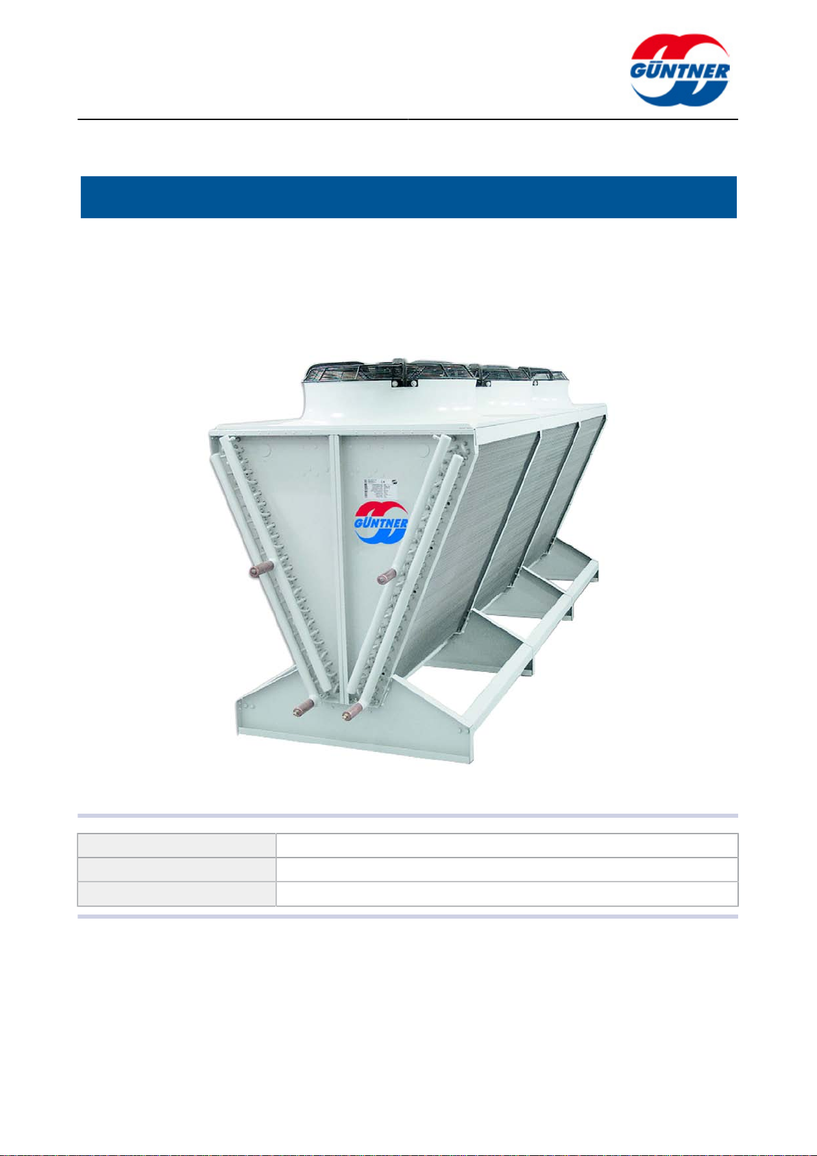
W air-cooled condenser – GVW
Translation of Original Operating Instructions
Transportation | Assembly | Operation | Maintenance
Product line: Condenser R134a, R22, R404a,...
Series variant description: W air-cooled condenser
Series: GVW
www.guentner.de
| 2010-09
Page 2

Contents
page 2 / 30
1 General safety instructions......................................................... 3
1.1 General instructions...........................................................................3
1.2 Safety instructions............................................................................. 4
2 Technical data............................................................................... 8
2.1 General information on the unit....................................................... 8
2.2 Technical data..................................................................................... 8
2.3 Sound specifications......................................................................... 8
3 Operation....................................................................................... 9
3.1 Definitions........................................................................................... 9
3.2 Fan motor............................................................................................ 9
4 Transportation and storage.......................................................11
4.1 Packaging.......................................................................................... 11
4.2 Transportation and unloading.........................................................11
4.3 Storage...............................................................................................14
4.4 Safety................................................................................................. 14
5 Assembly and installation......................................................... 15
5.1 Installation information....................................................................15
5.2 Installation guidelines......................................................................16
5.3 Assembly........................................................................................... 22
6 Start-up and operation...............................................................25
6.1 Start-up.............................................................................................. 25
6.2 Operation........................................................................................... 25
6.2.1 Normal operation................................................................................ 25
6.2.2 Taking out of service and final shutdown...........................................26
6.2.3 Modifications to the unit and non-permissible operating conditions and
working methods................................................................................ 26
7 Maintenance................................................................................ 27
7.1 General information......................................................................... 27
7.2 Cleaning.............................................................................................27
7.3 Maintenance and repair................................................................... 28
7.4 Water spray system instructions.................................................... 29
8 Güntner - Head office.................................................................30
| 2010-09
© Güntner AG & Co. KG
Page 3
1 General safety instructions
1.1 General instructions
Purpose
possible dangers associated with the device during
•
transport
•
setup and assembly
•
commissioning and operation
•
maintenance (cleaning, maintenance and servicing)
and to reduce such dangers to a minimum for persons, materials and the environment.
Binding regulations
•
EU Directive 97 / 23 / EG on pressure equipment (pressure equipment directive)
•
EU Directive 98 / 37 / EG on machines (machine directive)
•
EN 378; Parts 1 to 4; "Refrigeration systems and heat pumps, technical safety and environmental requirements" (a standard that supports the basic demands of the aforementioned EU Directives in accordance with CEN)
•
Law on Equipment and Product Safety (GPSG); including ordinances (GPSGV) valid for the
Federal Republic of Germany
•
BGR 500 "Operation of Work Equipment"; Chapter: "Operation of refrigeration systems, heat
pumps and cooling equipment"; valid for the Federal Republic of Germany
•
VDMA standard sheet 24243; Parts 1 to 5; "Impermeability of refrigeration systems and heat
pumps; leak test and leak detection"; valid for the Federal Republic of Germany
•
"Operating Instruction Manual in accordance with EN 378-2; Güntner axial condensers" (see
www.guentner.de)
page 3 / 30
| 2010-09
© Güntner AG & Co. KG
Page 4
•
Adhesive labels on the machine with regulations and indications by the manufacturer:
Apart from applying these Operating Instructions, the operator is obliged to observe the information and requirements outlined in the guidelines referred to above in order to maintain his warranty
claims.
These Operating Instructions apply for serial equipment. These Operating Instructions are only conditionally valid for custom-made equipment. In this case, the manufacturer must be consulted.
Should defects be detected in the unit, the manufacturer must be informed immediately so that he
can contribute to eliminating such defects.
To avoid ensuing damage caused by disruptions of operations, the customer must possess a
warning system which immediately indicates any kind of malfunction. Emergency measures must
be planned and prepared which in case of malfunctions help to avoid ensuing damage.
1.2 Safety instructions
page 4 / 30
WARNING
CAUTION
General
Device
CAUTION
The danger notes specified in the binding regulations generally apply according to section 1.1.
"General instructions".
CAUTION
All work on the units must be carried out by trained and experienced staff. Only approved materials may be used.
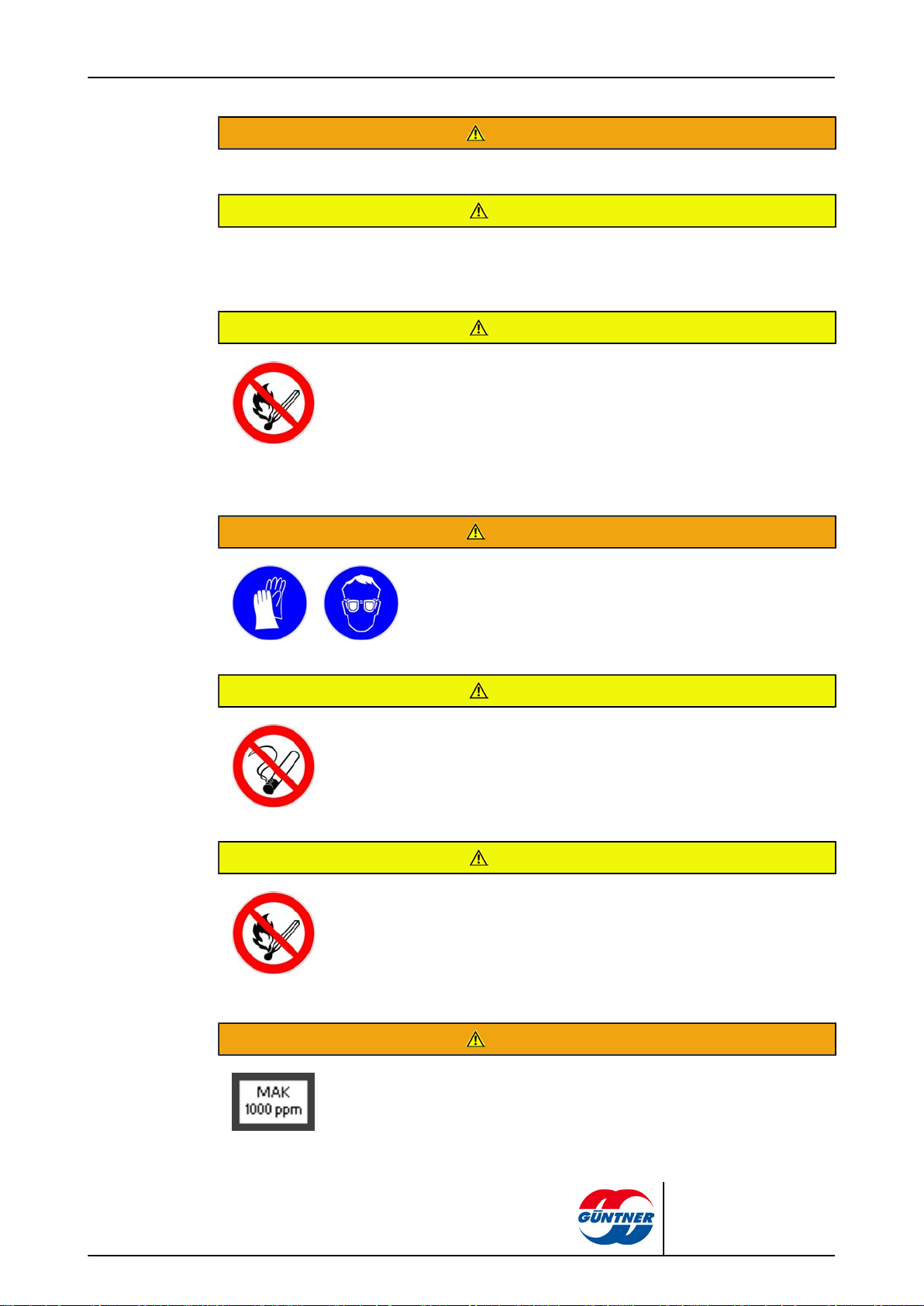
WARNING
Danger of burns when touching piping and distributor pipes at refrigerant temperatures above + 60 °C!
| 2010-09
WARNING
WARNING
Sharp edges and corners on the units (especially on the fins) can cut fingers and hands; wear
protective gloves.
© Güntner AG & Co. KG
Page 5

page 5 / 30
WARNING
Only access the equipment wearing sturdy, non-slip shoes.
CAUTION
Equipment without railings: Only access with lanyard rails.
CAUTION
Work on pressurised parts (pipelines, heat exchanger components): depressurise this section of
the system and/or siphon off the refrigerant from this section.
CAUTION
Maintenance work: equipment components must always be replaced with original spare parts.
CAUTION
The maximum operating pressure specified on the nameplate may not be exceeded.
Electrical system
CAUTION
If the unit is installed close to possible heat sources with danger of occurrence of high temperatures: take effective measures to protect the unit from excessive heat.
CAUTION
Electrical installation of the units: only be electricians in compliance with the relevant VDE rules
(or the national and international regulations) and the technical work regulations of the public utilities.
NOTICE
All work on fans or motors: it is imperative that the power supply is disconnected. During installation and maintenance work, the power supply to the unit must
be disconnected. The system must be secured against unintentional reactivation.
| 2010-09
© Güntner AG & Co. KG
Page 6
Fans
page 6 / 30
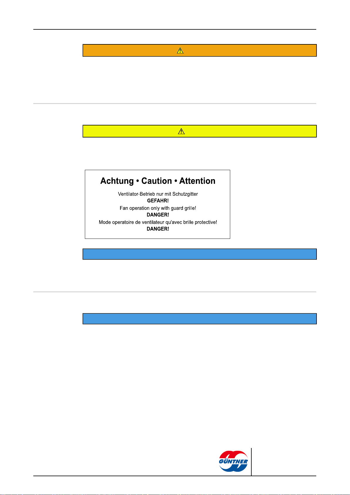
WARNING
The fan motors of the units must be provided with a deactivation facility in compliance with the
DIN EN 60204-1 standard to prevent unexpected starting (e.g. repair switch or via fuses in the adjacent switch cabinet). These deactivation devices must be secured to prevent them from being
unexpectedly or unintentionally reactivated when the power is dead (e.g. can be locked by a padlock).
CAUTION
Removal of the fan protection guards and working on the fans: only permissible with the power
supply switched off (power dead) and if appropriate protection is provided against unintentional
reactivation (remove fuses, put up warning signs).
Operating agents
NOTICE
Working on the fan air inlet and outlet guides: ensure that the power has been disconnected.
When work is concluded, do not leave any components near the fan as they will cause faults or
damage to the fans and/or heat exchangers upon reactivation.
NOTICE
The HFC refrigerants R134a, R404A, R407C, R507, R22 ... used are Group L1/A1 refrigerants in
compliance with classification according to flammability (L) and toxicity (A) in line with the EU Directive 97 / 23 / EG on pressure equipment (Pressure Equipment Directive):
•
Refrigerants which, when gaseous, are non-flammable in air regardless of their concentration.
•
Refrigerants with a time-weighted, average concentration that have no adverse effects on
the majority of staff who are exposed to this concentration every day during a normal 8-hour
working day and a 40-hour working week, which is greater than or equal to 400 ml/m³ (400
ppm(V/V)).
Staff are not exposed to any direct danger. Group L1/A1 refrigerants are however generally heavier than air and can flow into lower-lying areas. An increased concentration can arise in static air
at ground level. At high concentrations, there is a danger of cardia arrhythmias and suffocation
owing to low oxygen levels, especially at ground level.
| 2010-09
No access to the unit for unauthorised persons. It must be ensured that HFC refrigerant emanating from the unit is unable to penetrate the building or otherwise endanger people.
© Güntner AG & Co. KG
Page 7
page 7 / 30
WARNING
Spills of HFC refrigerant and oil must be impeded.
CAUTION
HFC refrigerant vapour and/or gas must be impeded from penetrating neighbouring rooms, staircases, yards, passages or drainage systems in close vicinity of the installation room and must be
discharged without risk.
CAUTION
Suitable fire-fighting equipment must be provided on site when working with
flames, e.g. grinding, welding, soldering etc.
•
Particular attention must be paid to the danger of ignition by spread oil
residue and HFC refrigerant.
•
The fire extinguishers to be provided must be available and ready for use in
sufficient numbers, and their extinguishing agents must not react dangerously with the HFC refrigerant.
WARNING
During troubleshooting after HFC refrigerant breakaway releases, please be aware of remaining HFC refrigerant under defervescence as splashes can lead to frostbite on skin and eyes.
CAUTION
Smoking is prohibited during work. To avoid inhalation of high vapour concentrations, working areas must be well ventilated.
CAUTION
Contact by HFC refrigerants with naked flames must be avoided as toxic combustion products can form. For this reason, welding or soldering work may only be performed after full removal of the HFC refrigerant from the respective section of the system. Good ventilation must be ensured. When performing emergency work in high concentrations of HFC refrigerant, it is imperative that selfcontained breathing apparatus independent of the ambient air is worn.
| 2010-09
WARNING
Constant compliance with the limit values must be ensured by monitoring the
HFC refrigerant concentration in the ambient air. With good air ventilation and
offtake, levels easily fall below the permissible limit values.
© Güntner AG & Co. KG
Page 8
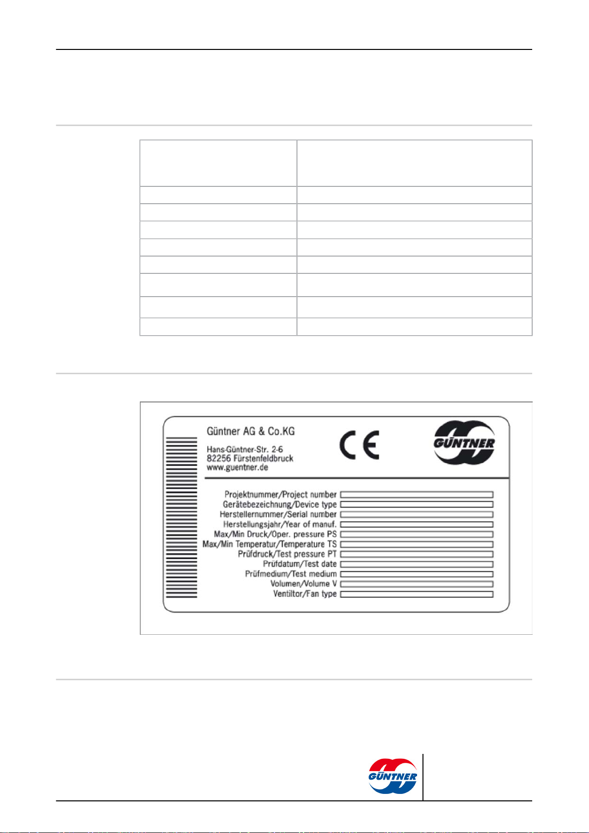
2 Technical data
2.1 General information on the unit
Manufacturer: Güntner AG & Co. KG
Unit name: See order-specific offer documents
Volume V: See order-specific offer documents
Fan type/number See order-specific offer documents
Fluid: See order-specific offer documents
Max. perm. pressure PS: 32 bar
page 8 / 30
Hans-Güntner-Strasse 2-6
D-82256 Fürstenfeldbruck
Perm. max./min. temperature TS:
Test pressure applied PT: 35.2 bar
Test medium: Dried air
2.2 Technical data
See order-specific offer documents and unit nameplate
- 50...+ 100 C
2.3 Sound specifications
| 2010-09
The indicated sound pressure level is based on the calculation (according to EN 13487) of the
sound pressure level on the surface of a cuboid area which is at 10 metres distance and parallel to
the referential envelope of the sound source (standard procedure for calculating the sound pressure
level, EN 13487, Annex C, distance mas per Eurovent).
© Güntner AG & Co. KG
Page 9
3 Operation
3.1 Definitions
3.2 Fan motor
This is an incomplete assembly.
A fan-ventilated refrigerant condenser is a component of a refrigeration system which condenses
refrigerant vapour via heat dissipation into the air which is then conveyed by fans across the dry
heat exchange surface. The heat exchanger comprises header inlets and outlets.
The refrigerant is the fluid used for exchanging heat in a refrigeration system and which absorbs
heat at low temperature and low pressure while dissipating heat at higher temperatures and higher
pressure, whereby the fluid then changes status.
The HFC refrigerants R134a, R404A, R407C, R507, R22 ... used are Group L1/A1 refrigerants (see
also section 1.2. ''Safety instructions'').
page 9 / 30
NOTICE
AC technology
During longer storage or downtime periods, the fans must be operated for 2 to 4 hours each
month.
NOTICE
In the case of fans with protection type IP55 or higher, any sealed condensate drain holes must be
opened at least every six months.
Motors with PTC resistors require an additional trigger device for the installed thermistors. Locking
is recommended to prevent reactivation. Max. 2.5 V test voltage or current-limited meters on thermistors.
When using step switching, the corresponding time delays must be taken into consideration for motors with 2 speeds.
For motors with direct start and a connection value > 4.0 kW, a startup current limitation (softstart
using thyristor) may be necessary.
NOTICE
When using other brands for frequency converter mode on external rotor motors (Ziehl-Abegg),
please observe the following: effective all-pole sinus filters should be fitted between the converter
and the motor (sinus-shaped output voltage, phase against phase, phase against protection conductor). Güntner frequency converter speed regulators feature this function as standard. Güntner
three-phase standard motors are suitable for operation on frequency converters.
| 2010-09
The fan motors can be operated by means of star-delta connection with two speeds and/or with
speed control. The direction of rotation must be checked. If the direction is wrong, it can be
changed by interchanging two phases.
© Güntner AG & Co. KG
Page 10

Electronic technology
The fan motors avail of a separate electronic power circuit. This power circuit is controlled via
Güntner Motor Management GMM. The motors can be powered at single-phase (1~, 200 - 277 V
AC, 50/60 Hz) and three-phase (3~, 380 - 480 V AC, 50/60 Hz) voltages. Please refer to the wiring diagrams or motor terminal box information for the electrical connection.
page 10 / 30
NOTICE
| 2010-09
© Güntner AG & Co. KG
Page 11

4 Transportation and storage
4.1 Packaging
Pallets, crates, cases HPE Packaging Directive by the Federal Association for
Wooden Packaging Materials, Pallets and Export Packaging
e.V. (incorporated society) and the VDM
Transportation packaging Güntner transportation packaging is made from environmen-
tally-friendly materials and is suitable for recycling
Please observe the symbols on the packaging, e.g.:
page 11 / 30
4.2 Transportation and unloading
The units designated for transport must be adequately protected against transport damage and
damaging atmospheric influences.
The units are delivered with approx. 1 bar overpressure (purified and dried air) (in accordance with
regulation ADR 1.1.3.2 c governing the transportation of hazardous materials)..
Before removing the sealing caps, check whether overpressure prevails.
An unpressurised unit indicates a leak (transport damage! leak test!).
If a unit arrives without pressure, the manufacturer must be consulted immediately.
Before installation, release the transportation pressure and remove the sealing caps.
| 2010-09
© Güntner AG & Co. KG
Page 12

page 12 / 30
NOTICE
The units must be protected against hard blows and hard setting down as well as against slipping
and mechanical damage.
NOTICE
Ongoing mechanical stress caused by uneven road surfaces and potholes as well as vibrations
during transport by sea can cause transport damage. Prior to transport by sea or in countries with
critical transport routes, add-on parts which can cause vibrations – especially fans and stands –
must be dismantled for transport.
An unloading device that is appropriate for the weight of the equipment (empty weight: see order-specific offer documents) must always be used and operators must be qualified for unloading
the equipment properly.
The equipment may only be lifted with a forklift with adequate fork length.
| 2010-09
CAUTION
When transporting the units by crane or forklift, even weight distribution must be strictly observed.
CAUTION
When lifting: observe the position of centre of gravity (see symbols for transportation).
CAUTION
When transporting by crane: Only secure hooks and shackles for load takeup devices at locations
specified by the manufacturer.
CAUTION
Connecting pieces and header tubes: Never use as attachment points for transportation.
© Güntner AG & Co. KG
Page 13

page 13 / 30
NOTICE
Special note: The sheet metal construction of the housing must not be crushed by belts – use
crane yokes if necessary (see transportation labels in the section on "General safety instructions").
| 2010-09
The units are transported as complete system components.
© Güntner AG & Co. KG
Page 14

The scope of delivery must be checked for completeness upon receipt. Any transport damage and/
or missing parts must be recorded on the bill of delivery. These facts must be reported immediately
in writing to the manufacturer.
4.3 Storage
Storage of the units: Only with protection against dust, contamination, moisture, damage and other damaging influences.
Letting the units stand around unnecessarily and permeation by humidity and dirt into the open unit
is not permissible on account of the danger of corrosion and contamination.
The same applies to unpacking the units, cleaning and installation before start-up.
4.4 Safety
page 14 / 30
NOTICE
CAUTION
The binding directives, standards and accident prevention regulations regarding the following
points must be observed:
•
lifting gear
•
cranes
•
load suspension devices in lifting gear operation
•
powered industrial trucks
| 2010-09
© Güntner AG & Co. KG
Page 15

5 Assembly and installation
5.1 Installation information
The units must be fixed at the fastening points appropriate for their weight and must be bolted down
with fastening bolts. The operator or installer of the equipment is responsible for ensuring that the
bolted connections are of the appropriate strength.
When fastening the units, the following instructions must be observed:
•
The diameters of the mounting holes have been statically determined by the manufacturer; the
fastening bolts must be adapted accordingly.
•
The fastening bolts must be secured against loosening by means of an appropriate locking device.
•
The fastening bolts must not be overtightened or stripped.
•
All fastening bolts must be tightened equally to achieve a load distribution that is as balanced as
possible.
•
When calculating the transferring bearing strength or suspension load, it is imperative that the
overall weight of the unit is taken into account. The bearing strength or suspension load is calculated as follows:
page 15 / 30
Total unit weight = Net unit weight
+ weight of tube contents
+ additional weight (moisture, dirt or similar )
X : safety coefficient (X ≥ 1)
•
In the course of maintenance intervals, the fastening bolts must be tested for functional safety
(see "Maintenance").
''Güntner axial condensers" are designed for outdoor operation. No external pressure drops are
considered.
NOTICE
The units must be installed perfectly horizontally.
CAUTION
When installed on the floor, all foundations must display the same height and retain this height
constantly and under load so that no mechanical stresses arise in the unit. The units must be anchored in their installation position to prevent the equipment from moving.
NOTICE
Installing the units: There must be an unobstructed flow of air into and out of the unit at all times
without air short-circuiting.
| 2010-09
© Güntner AG & Co. KG
Page 16

page 16 / 30
NOTICE
Installing the units: In such a way that they can be inspected, checked and maintained from all
sides at any time, i.e. there must be unobstructed access to the fluid-carrying and electrical components, connections and lines, and the pipeline labels must be identifiable as well as offering adequate space for testing.
Fluid-carrying pipelines: Protect against mechanical damage. Customer connections: Keep the
unit free of load when mounting; force may not be exerted on the distribution and header pipes.
Installing the units: Damage must not be incurred as a result of in-plant traffic or transportation
processes.
In areas used for inner-plant traffic, the pipelines to and from the units may only be installed without detachable connections and fittings.
When installing the units, it is imperative that the requirements formulated in the binding regulations (see section on "General safety instructions") regarding refrigerants, filling weight and heat
exchange systems are met.
The following document(s) serve(s) as installation plans for fastening the units:
See order-specific offer documents (see section 2. "Technical data").
5.2 Installation guidelines
When installing the units, the following regulations must be observed:
WARNING
CAUTION
CAUTION
| 2010-09
© Güntner AG & Co. KG
Page 17

When installing up to 3 units
page 17 / 30
| 2010-09
1 Air intake area
2 Direction of air
3 Height as per diagram
4 Clearance as per diagram
5 Cover plate
Requisite height of substructure in line with clearance by units GVW / GFW (only applicable for up
to max. 3 units).
Air intake:
from below: across both front and long sides
from the side: across both external heat exchanger surfaces
© Güntner AG & Co. KG
Page 18

page 18 / 30
1 Requisite height of substructure 3 Clearance between units: 0 mm
2 ribbed length of unit (m) 4 Clearance between units: 200 mm
(based on a ribbed 5 Clearance between units: 400 mm
height of 2* 1.20 m) 6 Clearance between units: 600 mm
7 Clearance between units: 800 mm
8 Clearance between units: 1000 mm
| 2010-09
© Güntner AG & Co. KG
Page 19

When installing up to 10 units
page 19 / 30
1 Air intake area
2 Direction of air
3 Height as per diagram
4 Clearance as per diagram
5 Cover plate
Requisite height of substructure in line with clearance by units GVW / GFW (only applicable for up
to max. 10 units).
Air intake:
from below: across front and long sides
| 2010-09
© Güntner AG & Co. KG
Page 20

page 20 / 30
1 Requisite height of substructure 3 Clearance between units: 0 mm
2 ribbed length of unit (m) 4 Clearance between units: 200 mm
5 Clearance between units: 400 mm
6 Clearance between units: 600 mm
7 Clearance between units: 800 mm
8 Clearance between units: 1000 mm
Correction factor for fewer than 10 units side by side:
Number of units
Number of fans per unit
side by side
2 3 4 5 6 7 8
2 0.7 0.6 0.5 0.4
3 0.8 0.7 0.6
4 0.9 0,8 0.7
5 0.9 0.8 0.7
6 0.9 0.8
7 1 0.9
8 1 0.9
9 1
10 1
| 2010-09
© Güntner AG & Co. KG
Page 21

When installing an unlimited number of units
page 21 / 30
1 Air intake area
2 Direction of air
3 Height as per diagram
4 Clearance as per diagram
5 Cover plate
Requisite height of substructure in line with clearance by units GVW / GFW.
Air intake:
from below: across both front sides
| 2010-09
© Güntner AG & Co. KG
Page 22

page 22 / 30
1 Requisite height of substructure 3 Clearance between units: 0 mm
2 ribbed length of unit (m) 4 Clearance between units: 200 mm
5.3 Assembly
All assembly work must be performed by qualified personnel. Damage caused by incorrect installation invalidates the manufacturer’s warranty obligations.
The unit may only be fastened at the anchoring points provided.
After installation (or reconnection), the unit must be cleaned on the inside and expertly evacuated in
accordance with the guidelines of the VDMA.
The unit is filled with dried air (see section 4.2. "Transportation and unloading"). Before discharging the dried air: all pipeline installation work performed by the customer must be completed.
(based on a ribbed 5 Clearance between units: 400 mm
height of 2* 1.20 m) 6 Clearance between units: 600 mm
7 Clearance between units: 800 mm
8 Clearance between units: 1000 mm
NOTICE
CAUTION
| 2010-09
Fluid-carrying connections: They must be absolutely free of mechanical stress.
The customer pipeline system must be provided with support before connecting
to the unit.
© Güntner AG & Co. KG
Page 23

page 23 / 30
CAUTION
Soldering and/or welding work is only permitted on depressurised units.
NOTICE
The pipeline installation must be kept as short as possible. As few bends must be used as possible and only those with large radii.
CAUTION
The general requirements associated with installing condensers must be taken into consideration
in accordance with the applicable regulations (see section 1. "General safety instructions").
CAUTION
It must be possible to lock the unit in the event of a leak. It must be possible to operate all installations intended for the discharge of emanating HFC refrigerant from a safe position.
CAUTION
The use of naked flames is prohibited at the installation site. Fire
extinguishers and extinguishing agents used to protect the unit
and operating staff must comply with the requirements outlined
in EN 378-3.
The following applies for the condenser piping:
•
Installation of pipes, valves and their components for lines to and from the unit in accordance
with EN 378-2 and the section on "Operating Refrigeration Plants, Heat Pumps and Cooling
Equipment" in BGR 500 "Operating Working Equipment".
| 2010-09
© Güntner AG & Co. KG
Page 24

page 24 / 30
•
Hard-solder all connections;Protect solder connection from overheating.
•
Install gas and liquid lines separately and insulate on both sides.
•
Avoid impact-solder connections; use copper pipe ends expanded on one side (capillary solder-
ing); avoid leaks; solder carefully and thoroughly.
•
Avoid overheating during welding (danger of excessive heat waste).
•
Use inert gas when welding.
•
After completion of the pipe installation and before connecting the units, perform expert internal
cleaning and evacuation in line with the guidelines of the VDMA.
| 2010-09
© Güntner AG & Co. KG
Page 25

6 Start-up and operation
6.1 Start-up
Before starting up the unit, the electrical protective measures must be checked and determined
along with readiness for operation using the following checklist:
•
All of the connections in the refrigeration system must be checked for leaks and correct installa-
tion in accordance with the applicable standards and regulations (see section on "General safe-
ty instructions"). , and the refrigeration system must be expertly evacuated in accordance with
the guidelines of the VDMA.
•
All screw connections (particularly to fans), fastenings, electrical connections etc. must be
checked for correct installation.
•
Prior to start-up, the fan belt tension and alignment of belt discs must be examined.
•
The complete wiring diagrams are to be found in the enclosed order-specific wiring diagrams.
•
The motor connection diagrams in the terminal boxes must be observed and correct adherence
thereto must be examined.
•
Before starting up, the wiring must be checked for correct installation and the electrical safety
measures must be checked for correct function.
•
Check whether fan power consumption matches the information on the nameplate.
•
Direction of rotation of fans must be checked and corrected if necessary.
•
All supply lines to the connecting boxes must be sealed in accordance with their insulation
class.
•
The fan power consumption must be checked on individual switching point settings.
•
During frequency converter operation, the respective EMC guidelines must be adhered to.
•
The supply line must always be fused in accordance with the smallest wire cross-section.
•
All specified control equipment must be checked for correct function.
•
All safety equipment must be checked on preset on/off switching point settings.
page 25 / 30
6.2 Operation
6.2.1 Normal operation
To operate the unit, the entire system and electrical installations must be in operation.
The unit is switched on by opening the relevant valves on the inlet and outlet side of the system and
by connecting it to the electrical system.
The unit is ready for operation once it has reached the specified operating point (see order-specific
offer documents.
The operating point setting
•
Condensing temperature
•
Air flow
•
Air intake temperature
is to be fixed as described in section 2.2 "Technical data".
If operating conditions deviate from the specifications (according to order-specific offer documents),
it is imperative that the manufacturer is consulted.
| 2010-09
© Güntner AG & Co. KG
Page 26

6.2.2 Taking out of service and final shutdown
The unit is taken out of service by disconnecting it from the system as a whole. In this case, the fluid-carrying pipes must be disconnected from the system as a whole and the fans must be disconnected from the electrical system.
CAUTION
When shutting down, observe the maximum operating pressure. If necessary,
take precautions to ensure that this level can not be exceeded.
The units are system components of a refrigeration system. Taking out of service and recommissioning must be carried out in accordance with system-specific configuration as per the applicable
standards and accident prevention guidelines (see "General safety instructions").
The pressure test after recommissioning may only be carried out using the appropriate media and
at suitable test pressure.
page 26 / 30
6.2.3 Modifications to the unit and non-permissible operating conditions and working methods
Modifications to the unit include:
•
changing the function as specified in the section on "Function"
•
changing the operating point in accordance with the section on "Technical data"
•
changing over to another fluid.
Non-permissible operating conditions and working methods as far as the warranty is concerned include:
•
changing the function as specified in the section on "Function"
•
changing the fan output (air volumes)
•
incorrect unit installation (see section on "Installation and assembly")
•
changing the operating point (heat transfer rate
•
changing the fluid
These changes, operating conditions and working methods may only be performed following agreement with and approval by the manufacturer if the warranty cover is to be maintained.
| 2010-09
© Güntner AG & Co. KG
Page 27

7 Maintenance
7.1 General information
7.2 Cleaning
The unit does not require special servicing. However, regular checking and maintenance will ensure
smooth operation. The maintenance intervals depend on the installation site and operating conditions. During maintenance checks, special attention should be given to looking for soiling,, leaks,
corrosion and vibrations.
For maintenance of the complex switch cabinet control, please refer to the separate Operating and
Maintenance Instructions provided by Güntner-Elektronik.
The planned and guaranteed heat transfer rate of the unit can only be provided if the heat exchanger coil is clean. Leaves, paper, dust, pollen and vapour deposits must be removed from the heat exchanger coil and from the immediate vicinity of the unit.
Dry dust or dirt can be removed using a brush, a hand brush, compressed air (against the direction
of air movement) or a powerful industrial vacuum cleaner.
page 27 / 30
NOTICE
If possible, always brush in the longitudinal direction of the fins. Use soft brushes.
NOTICE
Never brush sideways across the fins.
The jet of the cleaner should be held vertically to the heat exchanger coil where possible (max. deviation of ± 5°) to prevent the fins from bending.
Heavier wet or greasy soiling must be removed using a high-pressure water jet (max. pressure of
50 bar), steam pressure jet (max. pressure of 50 bar) at a minimum distance of 200 mm with a flat
jet nozzle, using a neutral cleaning agent where possible, and always against the direction of air
movement.
| 2010-09
Where possible, cleaning should be carried out from the inside to the outside and top down.
Keep cleaning until all of the dirt has been removed.
© Güntner AG & Co. KG
Page 28

page 28 / 30
CAUTION
When cleaning: the unit must be disconnected from the refrigeration system as well as the power supply. Water and steam jets must be kept well away from electric connections and electric motors.
NOTICE
Only use cleaning agents which are compatible with the unit materials; they may be neither aggressive nor corrosive.
Contamination and other soiling on the fans must be removed on a regular basis as it causes
unbalances and even disintegration or engine output loss. The actual fan motors are maintenance-free.
WARNING
Fans and protection guards that have been removed or opened for maintenance must be returned
to their original positions before recommissioning.
Mechanical cleaning with hard objects (e.g. wire brushes, screwdrivers or similar) will damage the
heat exchanger and is not allowed.
7.3 Maintenance and repair
Before commencing maintenance and repair work, the the HFC refrigerant must be siphoned off
and the electrical connections disconnected from the power supply to enable work to be carried out
safely.
Maintenance and repair work must be carried out in such a way that danger to people and goods is
avoided as much as possible.
Maintenance and repair work must be carried out in accordance with EN 378-4.
The repaired unit must be tested in accordance with EN 378-2.
The following plans serve as recommendations concerning care, maintenance and checkups:
Recommended care and maintenance plan
Measure Medium Intervals
component cleaning Mechanically, water or clean-
NOTICE
ing agent which is environmentally compatible or compatible with the material
As required (visual inspection)
| 2010-09
Overall cleaning Mechanically, water or clean-
ing agent which is environmentally compatible or compatible with the material
Leak test External visual inspection
(EN 378-2; Annexes A, B)
As required (visual inspection)
Depending on the leak rate
(see EN 378-2; Annex C)
© Güntner AG & Co. KG
Page 29

Measure Medium Intervals
Corrosion protection check See EN 378-2; Annex D Depending on the leak rate
Recommended checkup plan
page 29 / 30
(see EN 378-2; Annex C)
Component / Control
point
Heat exchanger
coil / Fluid connections
Fans Monthly *) Replace fan or re-
Housing / Fastenings
Electrical connections
*) control lamp in switch cabinet display
Intervals Measure When
See VDMA standard
sheet 24243
Every 3 months Tighten Immediately
Monthly *) Repair or replace Immediately
7.4 Water spray system instructions
Water spraying of a limited scope is recommended for reducing output peaks. When using water
quality, please note the following:
•
max. 50 hours/year
•
Soft water (£4odH); provide softening unit if necessary
•
Water spraying at approx. 3 bar
•
Pipeline system with nozzles can be provided.
See VDMA standard
sheet 24243
place runwheel
Immediately
Immediately
NOTICE
Danger of corrosion when using non-permissible water quality.
NOTICE
VDMA sheet: Please note "Instructions and recommendations concerning the operation and
maintenance of evaporation refrigeration systems".
| 2010-09
© Güntner AG & Co. KG
Page 30

8 Güntner - Head office
Address: Güntner AG & Co. KG
Tel.: +49 (0)8141 242-0
Fax: +49 (0)8141 242-155
E-mail: info@guentner.de
Internet: http://www.guentner.de
page 30 / 30
Hans-Güntner-Strasse 2 - 6
D-82256 Fürstenfeldbruck
| 2010-09
© Güntner AG & Co. KG
 Loading...