

Page 1
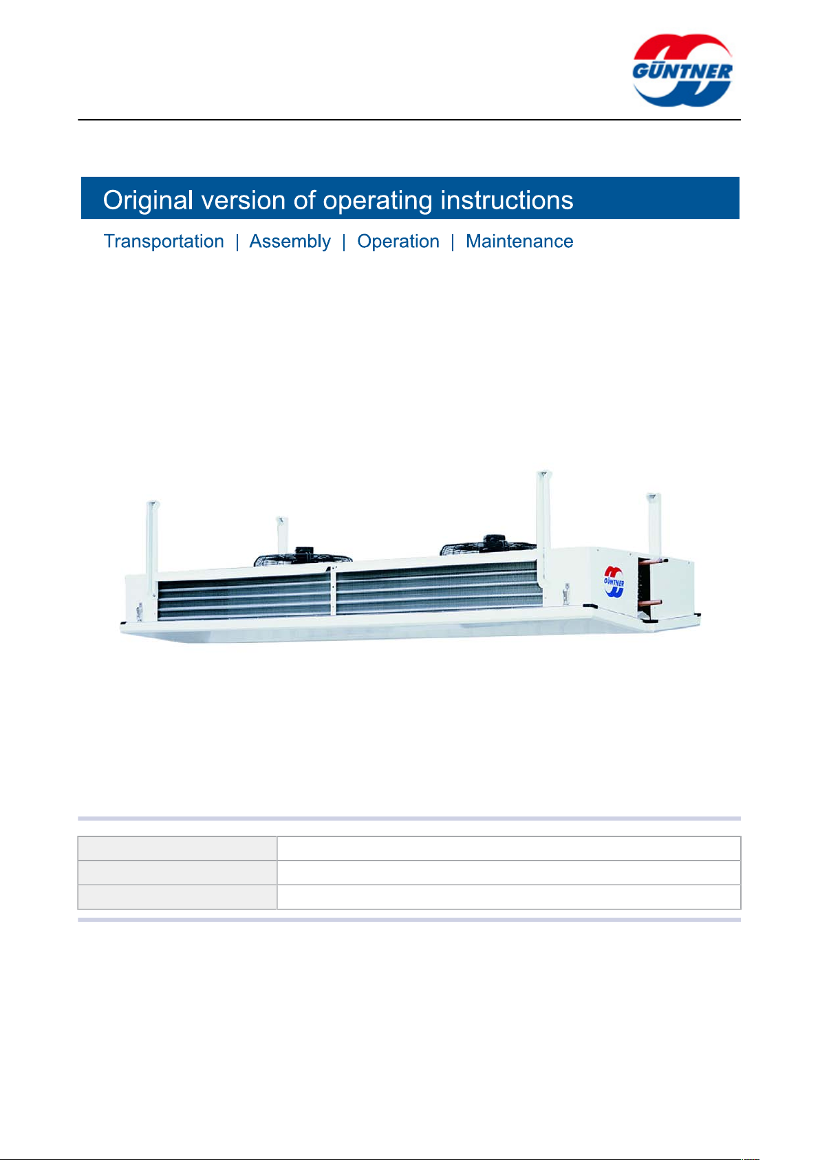
Air coolers – GGBK
Product line: Air cooler
Series variant description: Processing room glycol unit cooler
Series: GGBK
www.guentner.de
GGBK | 2010-09
Page 2

Contents
page 2 / 61
1 Important basic information........................................................5
1.1 Safety instructions............................................................................. 5
1.1.1 Observing operating instructions.......................................................... 5
1.2 Importance of the EN 378 series of standards – refrigeration sys-
tems and heat pumps – safety-related and environmental require-
ments................................................................................................... 5
1.3 Responsibilities.................................................................................. 5
1.3.1 Manufacturer's responsibilities............................................................. 5
1.3.2 Responsibilities of the system's installer.............................................. 6
1.3.3 Owner or operator responsibilities....................................................... 6
1.4 Legal notes..........................................................................................7
1.5 Operating instructions....................................................................... 7
1.5.1 Scope....................................................................................................7
1.5.2 Set-up and other applicable documents.............................................. 7
1.6 Conventions........................................................................................ 8
1.6.1 Typographical conventions................................................................... 8
1.6.2 List of abbreviations............................................................................. 8
1.7 Conventions for safety signs and notices.......................................9
1.7.1 General safety signs and their meaning in these operating instruc-
tions...................................................................................................... 9
1.7.2 Warning signs and their meaning in these operating instructions.........9
1.7.3 Prohibitory signs and their meaning in these operating instruc-
tions.................................................................................................... 10
1.7.4 Mandatory signs and their meaning in these operating instruc-
tions.................................................................................................... 11
2 Safety........................................................................................... 12
2.1 Labelling on the unit:.......................................................................12
2.1.1 Safety signs on the unit..................................................................... 12
2.1.2 Other signs and notes on the unit......................................................13
2.2 Basic safety notices.........................................................................15
2.2.1 How to act in an emergency.............................................................. 15
2.2.2 Personnel, care requirements............................................................ 16
2.3 Proper intended use.........................................................................16
2.3.1 Proper intended use........................................................................... 16
2.3.2 Operating conditions...........................................................................16
2.3.3 Improper use...................................................................................... 17
2.4 Mechanical residual hazards...........................................................18
2.4.1 Fins, sharp unit corners and edges................................................... 18
2.4.2 Fans.................................................................................................... 19
2.5 Electrical residual hazards.............................................................. 19
2.6 Thermal residual hazards................................................................ 20
GGBK | 2010-09
© Güntner AG & Co. KG
Page 3
page 3 / 61
2.6.1 Danger of burns................................................................................. 20
2.6.2 Frostbite hazard..................................................................................20
2.6.3 Frostbite hazard..................................................................................20
2.7 Residual hazards with the coolant/glycol......................................20
2.8 Residual hazards caused by vibrations.........................................22
2.9 Residual hazards caused by pressurised parts............................22
2.10 Residual hazards caused by defective installation.......................23
2.11 Residual hazards with break during operation............................. 24
2.12 Residual hazards caused by escaping objects or liquids............ 25
2.13 Residual hazards with disposal...................................................... 25
3 Technical data............................................................................. 26
3.1 Unit..................................................................................................... 26
3.2 Fans....................................................................................................26
4 Set-up and function....................................................................28
5 Fan motor.................................................................................... 29
6 Transportation and storage....................................................... 30
6.1 Safety................................................................................................. 30
6.2 Transportation and storage.............................................................30
6.3 Storage before installation.............................................................. 32
7 Set-up and start-up.................................................................... 33
7.1 Safety................................................................................................. 33
7.1.1 Safety instructions for set-up and start-up......................................... 33
7.1.2 System-side safety requirements....................................................... 34
7.1.3 Customer-side safety precautions...................................................... 35
7.2 Requirements at the set-up point...................................................36
7.3 Unpacking the unit........................................................................... 37
7.4 Installation......................................................................................... 38
7.4.1 System-side requirements for stress-free installation........................ 38
7.4.2 Mounting the unit................................................................................41
7.5 Notes on connecting the unit......................................................... 42
7.5.1 Connecting the drain line to the drip tray...........................................43
7.5.2 Connect the unit to the cooling equipment of the system.................. 43
7.5.3 Unit electrical connection and protection........................................... 44
7.6 Perform acceptance test..................................................................44
7.7 Test readiness for operation........................................................... 46
7.8 Putting the unit into operation for the first time........................... 46
GGBK | 2010-09
8 Operation..................................................................................... 47
8.1 Safety................................................................................................. 47
8.2 Putting the unit into operation........................................................47
8.3 Taking the unit out of operation..................................................... 48
© Güntner AG & Co. KG
Page 4

page 4 / 61
8.4 Shutting the unit down.................................................................... 48
8.5 Putting the unit into operation after a shutdown.......................... 49
8.6 Changing the unit over to another working fluid.......................... 49
9 Troubleshooting..........................................................................50
9.1 Safety................................................................................................. 50
9.2 Service............................................................................................... 50
9.3 Troubleshooting table...................................................................... 50
10 Maintenance................................................................................ 51
10.1 Safety................................................................................................. 51
10.1.1 Before starting all maintenance..........................................................51
10.1.2 With all maintenance work................................................................. 51
10.1.3 After all maintenance work................................................................. 52
10.2 Inspection and maintenance plan.................................................. 53
10.2.1 Fans.................................................................................................... 53
10.2.2 Unit heat exchanger........................................................................... 53
10.3 Maintenance work............................................................................ 55
10.3.1 Remove leaks.....................................................................................55
10.4 Clean unit.......................................................................................... 55
10.4.1 General............................................................................................... 55
10.4.2 Clean and defrost heat exchanger.....................................................55
10.4.3 Cleaning fans......................................................................................57
10.5 Defrosting the unit........................................................................... 58
10.5.1 Notes on defrosting............................................................................ 58
10.5.2 Defrost control.................................................................................... 59
10.5.3 Circulation air defrosting.....................................................................59
10.5.4 Electric defrosting ..............................................................................60
10.5.5 Further notes on defrosting................................................................ 60
GGBK | 2010-09
11 Plans/diagrams........................................................................... 61
11.1 Electrics documentation..................................................................61
11.1.1 Fan motor connection diagram.......................................................... 61
11.1.2 Connection diagram electrical defrost (selectable option; accessory on
customer request)...............................................................................61
11.2 Working fluidconnection diagram.................................................. 61
© Güntner AG & Co. KG
Page 5
page 5 / 61
1 Important basic information
1.1 Safety instructions
1.1.1 Observing operating instructions
CAUTION
Always keep the operating instructions in the unit's immediate vicinity at all times.
Ensure that the operating instructions are accessible to all people that have anything at all to
do with the unit at all times.
Ensure that the operating instructions are read and understood by all people that have anything at all to do with the unit.
1.2 Importance of the EN 378 series of standards – refrigeration systems and heat pumps – safety-related and environmental requirements
EN 378 deals with safety-related and environmental requirements for designing, constructing, producing, installing, operating, maintaining and disposing of refrigeration systems and cooling equipment.
EN 378 is oriented towards manufacturers, installers and operators of refrigeration systems and
cooling equipment (see section 1.2. Responsibilities).
The objective of EN 378 is to restrict the possible hazards of refrigeration systems, cooling equipment and their working fluids (refrigerants and coolants) for people, property and the environment
to a minimum.
Insufficient safety measures or non-compliance with safety-relevant regulations can result in:
•
Breaks or ruptures on components with the danger of escaping materials (hazards caused by
the influence of low temperatures, excess pressure, direct influence of the fluid phase, moving
machine parts).
•
Escaping working fluid after a break or leak because of defective design, improper operation, insufficient maintenance, repairs, filling and disposal (hazards caused by flammability, explosion
hazard, disturbance of nervous system, suffocation, panic)
•
Escaping working fluid after a break or leak because of defective design, improper operation, insufficient maintenance, repairs, filling and disposal (hazards caused by flammability, explosion
hazard, disturbance of nervous system, oxygen displacement, chemical reactivity, irritation of
respiratory centre, agitation, dizziness, vomiting and cramps, toxicity, chemical burns, frostbite,
panic)
1.3 Responsibilities
1.3.1 Manufacturer's responsibilities
The notes provided in these operating instructions on maintaining the unit's functional safety, preventing possible hazards when transporting, setting up and installing, start-up and operation, and
with maintenance activities (cleaning, servicing and repairing) refer exclusively to the unit.
GGBK | 2010-09
© Güntner AG & Co. KG
Page 6

The manufacturer's responsibilities are documented in the unit's version in acc. with EN 378-2 (design, manufacture and testing).
The construction, soldering and welding materials are configured so that they withstand the foreseeable mechanical, thermal and chemical stresses, and are resistant to the working fluid and the
working fluid/refrigerator oil mixture used.
The working fluid-carrying parts of the unit (core tubes, distributor tube and header outlet) are configured so that they remain tight with the foreseeable mechanical, thermal and chemical stresses,
and withstand the maximum permissible operating pressure.
Material, wall thickness, tensile strength, corrosive resistance, shaping process and testing are suitable for the working fluid used and withstand the possible pressures and stresses that might occur.
All responsibilities regarding the system's cooling equipment,, into which the unit is integrated, are
the exclusive responsibility of the people involved in the individual workflows.
1.3.2 Responsibilities of the system's installer
The responsibilities of the system installer are documented in the system's version (design, manufacture and testing – complete system: cooling equipment and refrigeration system) in acc. with EN
378-2.
page 6 / 61
Component supplier-system installer interfaces :
•
Inform Güntner AG & Co. KG if faults occur:
Inform Güntner AG & Co. KG immediately if faults occur during the set-up, installation, start-up
and operation.
The responsibilities of the system installer in particular include:
•
Planning and preparing emergency measures:
To avoid consequential damage caused by operational disruptions, a warning system which immediately signals all faults must be provided on-site. Prepare emergency measures that prevent
consequential damage for people and property should faults occur.
•
Install emergency STOP switches that can be actuated without danger.
•
Specify checking and maintenance intervals:
The system (complete system: cooling equipment and cooling plant)must be configured and
equipped with all required equipment for maintenance and sufficient servicing and testing in acc.
with EN 378-4.
With the integration of the unit into the refrigeration system's cooling equipment/ the working fluid
and version must not deviate from the order-related information specified in the order-related offer
documents.
The installer of the system must refer to the requirement for sufficient instruction of the operating
and supervision staff when operating and maintaining the system's cooling equipment .
It is recommended that the future customer staff – if possible – be present with the set-up and installation, with the tightness test and cleaning, with the filling with working fluid and with the setting
of the system's cooling equipment .
1.3.3 Owner or operator responsibilities
GGBK | 2010-09
The owner or operator responsibilities are documented in the operation, maintenance, servicing
and recovery of the system in acc. with EN 378-4.
The owner or operator must ensure that the proper people are sufficiently trained and qualified for
operating, monitoring and servicing the system (complete system: cooling equipment and refrigeration system) .
© Güntner AG & Co. KG
Page 7
page 7 / 61
The operating personnel for the system and cooling equipment must have sufficient knowledge and
experience with regard to the mode of operation, operation and daily monitoring of this system and
the cooling equipment .
Before the system start-up including the cooling equipment/the owner or operator must ensure that
the operating personnel are sufficiently instructed with the system's documentation (which is part
of the operating instructions) on the set-up, monitoring, mode of operation and servicing of the system including the cooling equipment/and the safety measures to be observed, and with regard to
the properties and handling of the working fluid to be used.
The owner or operator must ensure that when operating, monitoring and maintaining the system
and the cooling equipment/the working fluid and version must not deviate from the details specified
in the order-related offer documents.
Planning and preparing emergency measures: To avoid consequential damage caused by operational disruptions, a warning system must be installed on the customer's premises. Prepare emergency measures that prevent consequential damage for people and property should faults occur.
Responsibility remains with the owner or operator of the system and cooling equipement, if the
system and the cooling equipmentare used by somebody else, unless there is an agreement on
sharing responsibility.
1.4 Legal notes
Warranty claim expires as follows:
•
With faults and damages that can be attributed to non-compliance with the specifications of
these operating instructions.
•
With complaints that can be attributed to use of spare parts other than the original spare parts
specified in the order-related offer documents.
•
With changes to the unit (working fluid, version, function, operating parameters) vis-a-vis the or-
der-related information specified in the order-related offer documents without the manufacturer's
prior consent.
The operating instructions may not be reproduced electronically or mechanically, circulated,
changed passed on to third parties, translated or used otherwise, in full or in part, without Güntner
AG & Co. KG's prior explicit written approval.
1.5 Operating instructions
1.5.1 Scope
These operating instructions apply for all air coolers of the GGBK series.
You will find the precise type of your unit in the attached order-related offer documents.
NOTICE
1.5.2 Set-up and other applicable documents
GGBK | 2010-09
The unit's operating instructions include the following parts:
•
These instructions
•
Order-related offer documents
The order-related offer documents are attached to these instructions and include the following
information:
© Güntner AG & Co. KG
Page 8

– The order-related proper use as specified
– The order-related scope of delivery
– The order-related technical data
– The order-related drawings specifying customer, project number and order number
•
Motor connection wiring diagram in terminal boxes
These operating instructions are part of the operating instructions manual of the system, provided
by the system's installer .
1.6 Conventions
1.6.1 Typographical conventions
1.6.2 List of abbreviations
The following text markups are used in these operating instructions:
Bold Requires special attention!
Grey triangle Instructions
page 8 / 61
Abbreviations Meaning
EN 378 European Norm 378: Refrigeration systems and heat pumps; safety-related
and environmental requirements
EN European Norm
DIN German industrial standard (specification of a standard)
ISO International Standardization Organization
Emergency
STOP
°C Degrees Celsius (Celsius scale temperature)
bar Unit of pressure
I Litre (liquid volume)
Vol % Volume percent (concentration level relative to a volume)
IP Insulation protection
Q 6.3 Balancing quality
ppm parts per million, concentration figure, stands for "millionth"
Hz Hertz (frequency)
D Delta connection (rotating current: high speed)
S Star connection (rotating current: low speed)
Switch for immediately switching off the refrigeration system
GGBK | 2010-09
3~ 3-phase rotating current
1~ 1-phase alternating current
VDE "Verband der Elektrotechnik, Elektronik und
Informationstechnik" (Association for Electrical, Electronic & Information
Technologies)
© Güntner AG & Co. KG
Page 9
Abbreviations Meaning
TCC Technical Connection Conditions
EPC Electric Power Company
VDI "Verein Deutscher Ingenieure" (German engineers' association)
1.7 Conventions for safety signs and notices
1.7.1 General safety signs and their meaning in these operating instructions
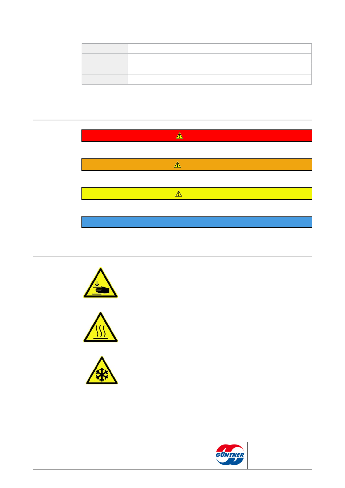
DANGER
Dangerous situation that will definitely cause serious injury or death if it is not avoided.
WARNING
Dangerous situation that could cause serious injury or death if it is not avoided.
page 9 / 61
CAUTION
Dangerous situation that could cause slight to moderate injury if it is not avoided.
NOTICE
Refers you to possible damage to property.
1.7.2 Warning signs and their meaning in these operating instructions
Warns against hand injuries!
Hands or fingers can be crushed, pulled in or otherwise injured with non-compliance.
Warns against hot surfaces!
The temperature is over +45 °C (protein clotting) and can cause burns.
Warns against cold!
The temperature is below 0 °C and can cause frostbite.
GGBK | 2010-09
© Güntner AG & Co. KG
Page 10

page 10 / 61
Warns against dangerous electrical voltage!
Danger of an electric shock if voltage-carrying parts are touched.
Warns against potentially explosive substances at set-up point
Use of ignition sources can cause explosions at set-up point.
Warns against fire-risk substances at set-up point.
Use of ignition sources can cause fire at set-up point.
Warns against harmful to health or irritant substances at set-up point
Contact with or inhaling harmful to health or irritant substances can cause injuries
or damage the health.
Warns against toxic substances at set-up point
Contact with or inhaling toxic substances can cause injuries or damage the health.
1.7.3 Prohibitory signs and their meaning in these operating instructions
Feuer, offenes Licht und Rauchen verboten!
Ignition sources must be kept away and ignition sources must not develop!
No smoking!
Smoking is forbidden.
GGBK | 2010-09
© Güntner AG & Co. KG
Page 11
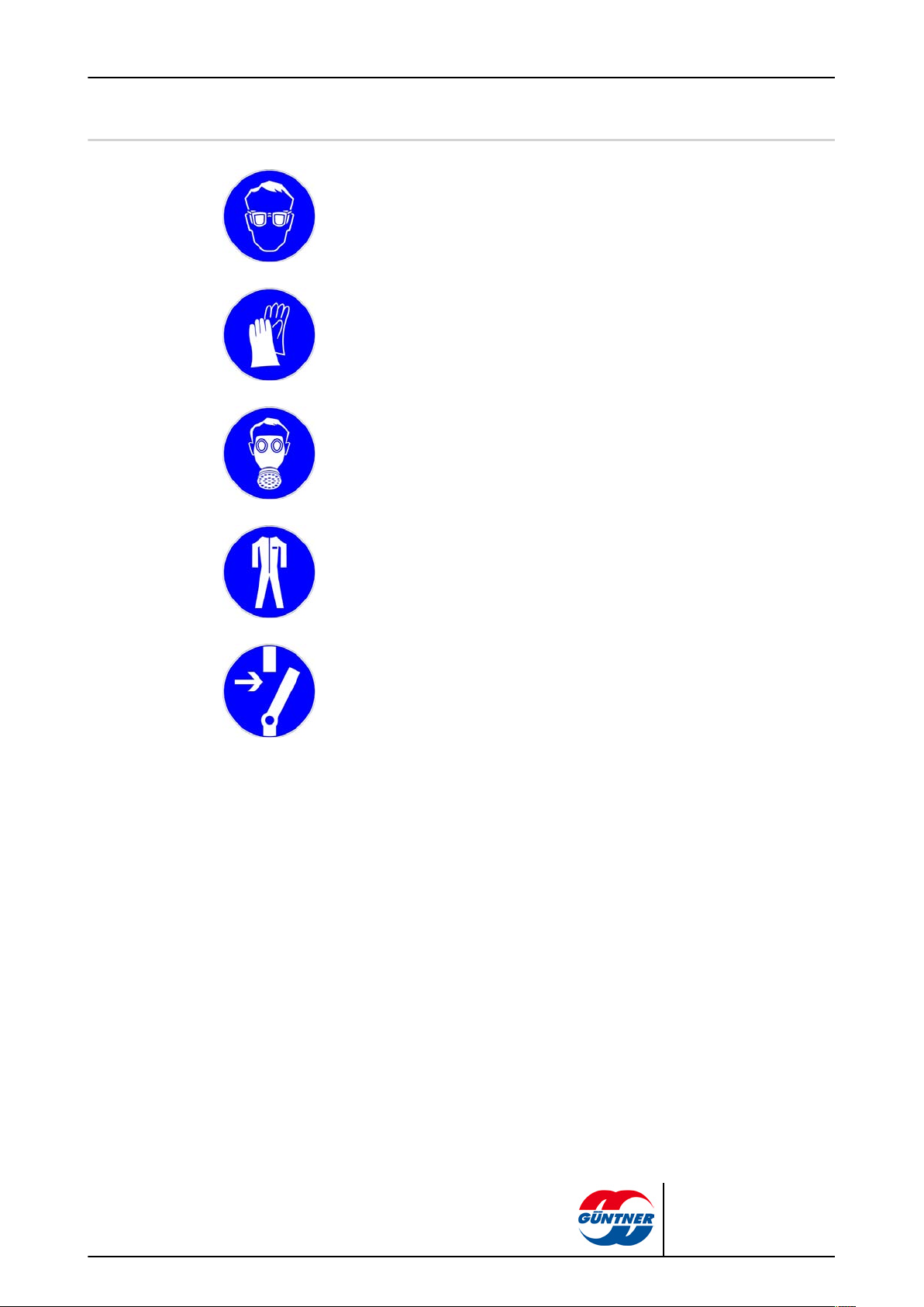
1.7.4 Mandatory signs and their meaning in these operating instructions.
Use eye protection!
Eye protection: Use protective cover, protective glasses or face protection.
Use hand protection!
Protective gloves must protect against mechanical and chemical dangers (see imprinted pictograms).
Use respiratory protection!
Breathing apparatus must be suitable for the working fluid used. Breathing apparatus must consist of:
•
At least two independent breathing devices (self-contained breathing apparatus)
page 11 / 61
Use protective clothing!
Personal protective clothing must be suitable for the working fluid used and for low
temperatures, and must have good heat insulation properties.
Activate before work!
Activate the electrical system and secure against switching on again before starting installation, maintenance and repair work.
GGBK | 2010-09
© Güntner AG & Co. KG
Page 12
2 Safety
Schallbretter
(Verpackung)
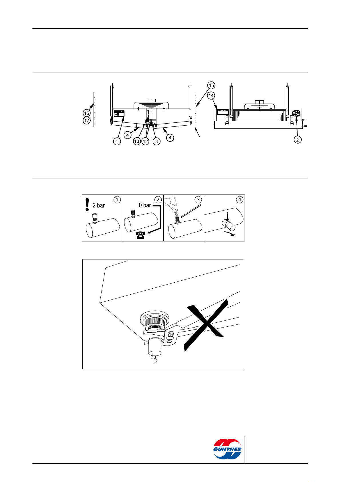
2.1 Labelling on the unit:
Placing of labels on the unit
2.1.1 Safety signs on the unit
Safety signs on the unit individually:
page 12 / 61
3 - "Transportation filling" warning sign next to Schrader valve
"Do not use wrench" warning sign beside tray drain
GGBK | 2010-09
© Güntner AG & Co. KG
Page 13
2.1.2 Other signs and notes on the unit
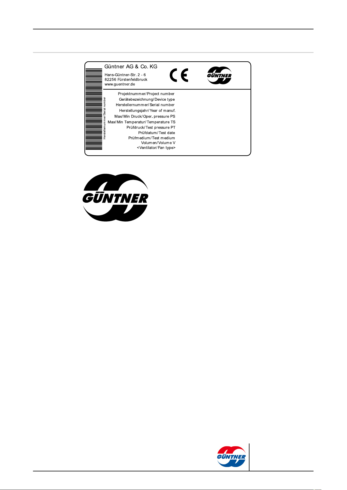
1 - Unit type plate
page 13 / 61
2 – Güntner logo
GGBK | 2010-09
© Güntner AG & Co. KG
Page 14
12 - Connections ON and OFF
page 14 / 61
GGBK | 2010-09
17 - Trailer loading – Ceiling-mounted air cooler
© Güntner AG & Co. KG
Page 15
2.2 Basic safety notices
2.2.1 How to act in an emergency
Danger of injuries and damage to property!
The unit is operated as standard with the coolant, ethylene glycol (synonyms:
ethane-1,2-diol, glycol). When using other coolants, prior agreement with the
manufacturer is an absolute must.
Ethylene glycol is a colourless, slightly viscous, not very fluid, water-mixable,
deliquescent liquid with a sweet smell or taste.
Ethylene glycol is flammable and explosive at higher temperatures in a vapour/
gaseous state.
With skin contact ethylene glycol causes slight irritation with the danger of skin
absorption; with eye contact mucous membrane irritation; with ingestion agitation with disruption of the central nervous system; with prolonged endangering
effect – fatigue, coordination disruption, unconsciousness, kidney damage.
Keep ethylene glycol away from ignition sources. No smoking!
Ethylene glycol vapours are heavier than air and may flow off to rooms on a lower level. In still air there may be an increase of the ground level concentration.
With high concentrations, there is a danger of suffocation due to reduced oxygen concentration, especially at ground level.
Avoid contact with skin, floor, clothing! Remove contaminated, soaked clothing
immediately!
Do allow contact with heavy oxidation agents (chromo-sulphuric acid, potassium permanganate, smoking sulphuric acid, or similar)! Danger of strong reactions!
Unauthorised people must not have access to the unit. When setting up it must
be ensured that the coolant escaping from the unit cannot penetrate the interior
of the building or put people at risk in any other way.
Safety measures and procedure:
•
With unexpected serious coolant breaks, activate the emergency STOP
switch set up in a safe place, e.g. with:
– Visibly escaping coolant from the heat exchanger or pipe components.
– Sudden large release (release and evaporation of the greater part of the
entire coolant in a short time, e.g. in less than 5 minutes).
•
Have experienced, trained personnel with prescribed protective clothing perform all necessary protective and other measures:
– Use respiratory protection.
– Use a room air-independent breathing apparatus with maintenance work
in high coolant concentrations in the room air.
– Ensure the set-up room is well ventilated.
– Divert escaped coolant liquid safely in acc. with EN 378-3.
page 15 / 61
WARNING
GGBK | 2010-09
© Güntner AG & Co. KG
Page 16
2.2.2 Personnel, care requirements
The unit must only be put into operation, operated, maintained and repaired by trained, experienced and qualified personnel. People that are responsible for the operation, maintenance, repair
and evaluation of systems and their components must have the required training and specialist
knowledge for their work in acc. with EN 378-1 to be qualified. Qualified or expert means the ability to satisfactorily perform the activities required for the operation, maintenance, repair and evaluation of refrigeration systems, cooling equipment and their components.
The unit may be operated by operating personnel that have no specific knowledge of refrigeration
engineering, but have sufficient knowledge and experience with regard to the mode of operation,
operation and daily monitoring of this system, and the cooling equipment. This operating personnel may not make any interventions or settings on the system and the cooling equipment.
Changes to the unit, which the manufacturer has first agreed to in writing, may only be made by
the instructed and qualified personnel.
Electrical installation:
Work on the electrical equipment may only be performed by personnel that have the required expertise (e.g. an electrician or an electro-technically instructed person), and who are authorised by
the operator, in compliance with the respective VDE regulations (and national and international
provisions) and the TCCs of the EPCs.
page 16 / 61
CAUTION
2.3 Proper intended use
2.3.1 Proper intended use
2.3.2 Operating conditions
Processing room air coolers of the GGBK series are intended for installation in a refrigeration system and are used for the draught-free cooling of processing rooms and draught-free, low noise air
distribution in work areas and rooms.
The unit is delivered for operation with a specific operating point:
•
Coolant flow temperature
•
Coolant return temperature or circulating coolant volume
•
Airflow volume
•
Air inlet temperature
•
Relative air humidity.
The specified operating point is provided in the order-related offer documents.
The unit is a component of a cooling unit a cooling system including its working fluid circuit. The
purpose of these operating instructions, as part of the operating instructions manual (of which these
operating instructions are a part), is to restrict the dangers to people and property and the environment from the unit and the working fluid used in it to a minimum. These dangers are essentially
connected with the physical and chemical properties of the working fluid and with the pressures and
temperatures that occur in the working fluid-carrying components of the unit see Residual hazards
with the coolant/glycol, page 20.
GGBK | 2010-09
© Güntner AG & Co. KG
Page 17
Danger of injuries and damage to property!
The unit must only be used in acc. with the proper intended use. The operator must ensure that
when operating, monitoring and maintaining the unit, the fluid and version do not deviate from the
order-related information specified in the order-specific offer documents.
The operator must ensure that maintenance measures are performed in compliance with the
system's operating instructions manual.
Filling the unit is only permitted following written approval by the manufacturer. You will find the
order-related proper use as intended in the order-specific offer documents.
Do not exceed the max. operating pressure given on the unit's type plate.
2.3.3 Improper use
page 17 / 61
WARNING
WARNING
Danger of injuries and damage to property!
Working fluids and their combinations with water or other substances in the working fluid-carrying components have chemical and physical effects from the inside on the materials surrounding
them. The unit must only pressurised with coolant/. Pressurising the unit with another working
fluid results in,
■
the structural, soldering and welding materials used do not withstand the foreseeable mechanical, thermal and chemical stresses, and the pressure that can occur during operation
and when shut down is not withstood.
■
material, wall thickness, tensile strength, corrosive resistance, shaping process and testing
are not suitable for the working fluid used and do not withstand the possible pressures and
stresses that might occur.
■
the unit not being resistant to the other working fluid and the other working fluid mixture.
■
the unit not remaining tight during operation and when shut down.
■
a possible sudden escaping of working fluids could directly endanger people and/or property
and the environment.
The maximum permissible operating pressure specified on the type plate must not be exceeded!
If the operating pressure is exceeded,
■
the structural and welding materials will not withstand the foreseeable mechanical, thermal
and chemical stresses and the pressure that can occur during operation and when shut down.
■
the unit will not remain tight during operation and when shut down.
■
there may be a possible sudden escaping of working fluids after a break or leakage on work-
ing fluid-carrying components, which would result in the following dangers:
– Danger of escaping materials
– Irritations and health hazards
– Fire hazard
– Explosion hazard,
– Strong chemical reactivity
– Frostbite hazard
– Suffocation hazard
– Hazards caused by panic reactions,
– Environmental pollution
GGBK | 2010-09
© Güntner AG & Co. KG
Page 18
page 18 / 61
WARNING
Air coolersmay not be used
■
where it is possible that short or prolonged effect caused by contact, inhalation or ingestion of
the working fluid glycol might result in harmful hazards.
■
where the possibility exists of a sudden large release of the greater part of the entire working
fluid filling in a short time (e.g. in less than 5 minutes).
The unit must not be changed without prior written consent by Güntner AG & Co. KG. Changes to
the unit are:
■
Changing the operating point (see chapter Unit)
■
Changing the fan capacity (air volume)
■
Changing the working fluid flow-through volume
■
Changing over to another working fluid
The unit must not be operated if safety devices recommended by the manufacturer are not available, not properly installed or not fully functional.
The unit must not be operated if it is damaged or demonstrates faults. All damages and faults
must be reported to Güntner AG & Co. KG immediately and must be removed immediately.
Work on the unit must not be performed without the personal protective equipment specified in
these operating instructions.
2.4 Mechanical residual hazards
2.4.1 Fins, sharp unit corners and edges
Warns against hand injuries!
Danger of cuts on hands and fingers on the fins and on sharp corners and
edges of the unit.
Use reliable hand protection!
WARNING
GGBK | 2010-09
© Güntner AG & Co. KG
Page 19
2.4.2 Fans
page 19 / 61
WARNING
Danger of cutting off, pulling in!
There is a danger of cutting off fingers on the rotating fan blades, injury hazard
for the hands and pulling in danger for loose elements such as hair, necklaces
or clothing parts.
Do not operate fans without guard grille. Pinch/trap point hazard!
With automatic fan start during maintenance work there is a danger of pinching/trapping for the hands and fingers.
Power off the unit before you begin maintenance work with which you must remove the guard grille. Secure the unit against unintentional switching on again
by removing the electric fuses for the unit. Secure the unit with a suitable warning sign referring to unintentional switching on.
2.5 Electrical residual hazards
Warns against dangerous electrical voltage!
Direct and indirect contact with voltage-carrying parts of motors and electrical
lines can cause serious injuries or death.
Power off the unit before you begin maintenance work. See the refrigeration
system's system documentation for this. Secure the unit against unintentional
switching on again by removing the electric fuses for the unit. Secure the unit
with a suitable warning sign referring to unintentional switching on.
Please note that the mains cables may also be carrying voltage, even if the unit
is powered off.
Work on electrical equipment must only be performed by people that have the
required expertise (e.g. an electrician or an electro-technically instructed person) and who are authorised to do so by the operator.
WARNING
GGBK | 2010-09
© Güntner AG & Co. KG
Page 20

2.6 Thermal residual hazards
2.6.1 Danger of burns
Warns against hot surfaces!
In electric defrosting operation the unit's heat exchanger and the electric heater
rods have temperatures of over +45 °C. Contact can cause burns.
Use hand protection!
2.6.2 Frostbite hazard
Warns against cold!
In refrigerationoperation the heat exchanger and pipes possibly have a temperature below ±0 °C. Contact can cause frostbite.
Use hand protection!
page 20 / 61
WARNING
WARNING
2.6.3 Frostbite hazard
WARNING
Warns against frostbite!
With insufficient frost protection filling and operation in areas with frost hazard
the unit can cause frostbite. With units that cannot be drained completely the
hazard of frostbite also remains after draining. It is imperative that the proper
ventilation be ensured when draining the unit. With pressure test, operation and
shutdown of units filled with water or insufficient frost protection filling or insufficient setting of the , these are disrupted at minus temperatures.
2.7 Residual hazards with the coolant/glycol
WARNING
Danger of injuries and damage to property!
General description of hazards:
The unit is operated as standard with the coolant ethylene glycol (synonyms: ethane-1,2-diol, glycol) . When using other brine/coolants, coolants prior agreement with the manufacturer is an absolute must.
GGBK | 2010-09
© Güntner AG & Co. KG
Page 21

page 21 / 61
Ethylene glycol is a colourless, slightly viscous, not very fluid, water-mixable, deliquescent liquid
with a sweet smell or taste.
Unauthorised people must not have access to the unit. When setting up it must be ensured that
the coolant escaping from the unit cannot penetrate the interior of the building or put people at
risk.
WARNING
Danger of harm to health!
With skin contact ethylene glycol causes slight irritation with the danger of skin absorption; with
eye contact mucous membrane irritation; with ingestion agitation with disruption of the central
nervous system; with prolonged endangering effect – fatigue, coordination disruption, unconsciousness, kidney damage.
•
Avoid contact with skin, eyes and clothing! Remove contaminated, soaked clothing immedi-
ately!
•
Ethylene glycol vapours are heavier than air and may flow off to rooms on a lower level. In
still air there may be an increase of the ground level concentration. With high concentrations,
there is a danger of suffocation due to reduced oxygen concentration, especially at ground
level.
•
To avoid the inhalation of high vapour concentrations, the working rooms must be well aired.
•
Test the tightness of the unit regularly, as specified in these operating instructions.
Ignition and fire hazard!
Ethylene glycol is flammable and explosive at higher temperatures in a vapour/
gaseous state.
•
Keep ethylene glycol away from ignition sources.
•
Suitable fire fighting equipment must be provided on site with work involving
fire or sparks, such as grinding, welding, etc.
•
Ensure that the provided fire fighting equipment is provided in sufficient
quantities, that it functions properly and that the extinguishing agent does not
react with the coolant.
•
No smoking!
Danger of poisoning!
Contact of the coolant with open fire must be prevented, as toxic combustion
products can form.
•
Prevent coolant contact with open fire!
•
Welding and soldering must therefore only take place after completely draining the relevant section of the system of the coolant. Ensure good ventilation
here!
•
Do not bring into contact with heavy oxidation agents (chromo-sulphuric
acid, potassium permanganate, smoking sulphuric acid, or similar)! Danger of
strong reactions!
GGBK | 2010-09
© Güntner AG & Co. KG
Page 22

Frostbite hazard!
With insufficient frost protection filling and operation in areas with frost hazard
the unit can cause frostbite. With units that cannot be drained completely the
hazard of frostbite also remains after draining.
•
It is imperative that the proper ventilation be ensured when draining the unit.
•
With pressure test, operation and shutdown of units filled with water or insufficient frost protection filling or insufficient setting of the coolant, these are
disrupted at minus temperatures.
2.8 Residual hazards caused by vibrations
WARNING
Danger of injuries and damage to property caused by escaping materials
If fans are damaged during fan operation, flying parts of the fan blades can injure people or cause
damage to property close to the fan.
Fans, components and cables in the system, and in the cooling equipment must be designed,
constructed and integrated so that dangers caused by vibrations that it or other parts of the system generate (complete system = refrigeration system and cooling equipment), are reduced to an
absolute minimum, while incorporating all available means for reducing vibrations, preferably at
the source.
page 22 / 61
NOTICE
Damage to property caused by vibrations
Vibrations that are increased by imbalances, as created by dirt, icing or fan blade damage, are
regularly caused with fan operation. The vibrations are transferred to the unit, where they can
cause damage and damage the unit mounting or system cooling unitcomponents connected to
the unit.
Check the fan blades and guard grille regularly for dirt and frosting and/or icing and the fans'
smooth running (see Fans, page 53).
2.9 Residual hazards caused by pressurised parts
WARNING
Injury and damage to property caused by pressurised components that contain coolant!
Breaks in pressurised pipes or pressurised components of the unit can cause injuries or damage
to property caused by escaping materials. A sudden large release of the working fluid with its hazardous properties after a break or leak on pressurised components of the unit can cause the following hazards:
■
Irritations and health hazards
■
Strong chemical reactivity
■
Flammability
■
Explosion hazard
■
Suffocation
■
Panic,
■
Environmental pollution
GGBK | 2010-09
© Güntner AG & Co. KG
Page 23

Ensure that the unit in question is pressure-free before maintenance work begins or remove the
working fluid from the unit in question.
Only perform maintenance work – especially soldering and welding work – on the unit in question
after completely removing the working fluid from the unit.
2.10 Residual hazards caused by defective installation
WARNING
Injuries and damage to property caused by defective installation!
Defective installation results in hazards caused by:
■
Break or leak on liquid-carrying unit components and pipes
■
Uneven load distribution on the fixtures with the danger of stresses within the unit or unit dis-
placement (breaks or leaks on fluid-carrying components of the unit and pipes; danger of
breaking off).
■
Insufficient securing of working fluid-carrying lines against mechanical damage! On-site con-
nections: loaded installation; effect of forces on the distribution and header pipes with the
danger of breaks or leaks on fluid-carrying components of the unit and pipes; danger of break-
ing off!
■
Break-off and fall danger of the unit with hazard of escaping working fluid and exposed electri-
cal cables.
■
Danger of damage caused by environment-conditional hazard sources (production, transport
and other processes at the set-up point).
■
Unit functional faults caused by air inlet/outlet obstructions.
■
Obstruction of all-side inspection, checks and maintenance, i.e. no unobstructed accessibility
to the working fluid-carrying and electrical components, connections and cables, no recognis-
able identifiers on the pipes and insufficient space for tests.
Ensure that:
page 23 / 61
•
The units are to be installed on the fixing points corresponding with their weights and tight-
ened with fixing bolts. The operator or installer is responsible for ensuring that the bolted con-
nections are of an adequate strength.
•
The diameters of the mounting holes have been statically determined by the manufacturer and
the fixing bolts are adapted accordingly.
•
The fixing bolts are secured against loosening by means of an appropriate locking device.
•
The fixing bolts are not overtightened or stripped.
•
All fixing bolts are tightened equally to achieve a load distribution on the connections that is
as balanced as possible.
•
All fixing points maintain the same spacing to the fixing level permanently and under load, so
that no mechanical stress occurs in the unit structure. The units are anchored in their fixing
position in order to prevent the equipment from moving.
•
The functional safety of the fixing bolts is tested as part of the maintenance periods. see Main-
tenance, page 51.
•
The unit is fixed and set up so that it is not damaged by environment-conditional hazard
sources (production, transport and other processes at the set-up point) or its functioning is
not disturbed by the interventions of unauthorised persons.
•
The units are fixed and set up with sufficient slopes for drip water flow.
•
The units are fixed and set up so that unobstructed air inlet/outlet is constantly available with-
out any air short circuiting.
•
The units are fixed and set up so that unobstructed heater rod swap-out with electric defrost-
ing is constantly available (option: accessory at customer's request).
GGBK | 2010-09
© Güntner AG & Co. KG
Page 24

•
The units are fixed so that they can be inspected, checked and maintained from all sides at all
times, i.e. there must be unobstructed access to the refrigerant-carrying and electrical compo-
nents, connections and lines, the pipeline labelling must be identifiable and adequate space
must be available for testing.
•
The working fluid-carrying lines are protected against mechanical damage. On-site connec-
tions: when installing keep the unit free of load; force must not be exerted on the distribution
and header pipes.
•
The following must be observed without fail when installing the unit:
– Imperative adherence to spacing from objects that could be endangered coolant effects.
– Easily flammable materials must not be placed below the unit.
– Set up and fix units as follows: In areas that are used for inner-plant traffic, the pipelines
to and from the unit must only be installed with connections and fittings that cannot be removed.
– Under-cooled liquid must only be present in the lowest possible amount in system sec-
tions in shutdown state – minimized number of "fluid sacks".
– That when switching over a duty pump to a reserve pump no liquid, cold refrigerant re-
mains in the pump.
2.11 Residual hazards with break during operation
page 24 / 61
WARNING
Injuries and damage to property caused by break during operation!
•
Residual hazards with break during operation (see Residual hazards caused by defective in-
stallation, page 23),
•
Non-compliance with maximum permissible operating pressure (see Operating conditions,
page 16),
•
Disregarding pressurised line sections with maintenance (see Residual hazards caused by
pressurised parts, page 22).
•
Disregarding residual hazards caused by vibration (see Residual hazards caused by vibra-
tions, page 22)
result in ruptures during operation and maintenance. This results in dangers caused by
•
escaping materials (see Residual hazards caused by pressurised parts, page 22).
•
released working fluid (see Residual hazards with the coolant/glycol, page 20).
Ensure that:
•
The installation is fault-free.
•
The maximum permissible operating pressure is always adhered to.
•
Pressurised line sections are de-pressurised before all maintenance and repair work.
•
Vibrations from the refrigeration system (vibrations caused by refrigeration system compres-
sors, components and lines), from the cooling plant (vibrations caused by pumps, compo-
nents and lines) of the complete system and from the fan (imbalances caused by frosting, ic-
ing or dirt build-up or damages) are reduced with all available means and brought down to an
absolute minimum.
GGBK | 2010-09
© Güntner AG & Co. KG
Page 25

2.12 Residual hazards caused by escaping objects or liquids
WARNING
Injuries and damage to property caused by escaping objects or liquids!
Residual hazards caused by escaping objects and liquids (see Residual hazards with break dur-
ing operation, page 24).
2.13 Residual hazards with disposal
WARNING
Danger of injuries and damage to property caused by working fluid, , , glycol!
The following notes are recommendations for the proper professional disposal of the unit. Applicable waste disposal laws are binding for the country of operation:
■
Disposal must only be carried out by experts.
■
All unit components, e.g. working fluids, coolant, heat exchangers, fans must be disposed of
properly as specified.
■
Used working fluid that is not determined for reuse, must be treated as waste and safely dis-
posed of. There must be no emissions into the environment.
■
The working fluid must not be filled in a liquid container that contains another or an unknown
working fluid. This other or unknown working fluid must not be released into the atmosphere,
but rather identified, treated again, or properly disposed of as specified.
■
An officially authorised facility can be used for destroying the working fluid.
■
It must be ensured that all unit components containing working fluids and coolant are dis-
posed of properly as specified.
■
The unit consists predominantly of the basic materials copper, aluminium, coated steel (tube
and tube coil (heat exchanger) and casing), steel, aluminium, copper, polyamide (motors),
stainless steel, copper, insulating material, (heater rods for electrical defrost; option; acces-
sory available on request). These materials can be handled by the waste industry, including in
paint-treated state, to recycling via mechanical and thermal separation.
■
Before scrapping the working fluid-carrying unit components must be drained, whereby the
pressure drops must be increased with compressed air as required when draining.
page 25 / 61
GGBK | 2010-09
WARNING
Danger of environmental pollution!
If any spills or escapes occur, immediately absorb them with a universal binder (e.g. Chemizorb®)
and transfer them to the special waste in acc. with the specifications of the absorbed substance.
Güntner AG & Co. KG's transportation packaging is made from environmentally compatible material
and is suitable for recycling.
© Güntner AG & Co. KG
Page 26

3 Technical data
3.1 Unit
The fans' capacity values depend on the ambient temperature and on the air resistance at the setup point.
All electrical parts must be installed in acc. with EN standards.
Project number See order-related offer documents
Unit name See order-related offer documents
Manufacturer number See order-related offer documents
Production year See order-related offer documents
Working fluid See order-related offer documents
Volume See order-related offer documents
page 26 / 61
NOTICE
3.2 Fans
Permissible operating pressure 16 bar
Test pressure 17.6 bar
Permissible operating temperature -50 ... +100 °C
Permissible ambient temperature -30 ... +40 °C
Permissible air humidity 100 %
Test date See order-related offer documents
Test medium Dry air
Airborne noise emitted See order-related offer documents In acc. with stan-
dard procedure for calculating sound level in acc. with
EN 13487; Annex C (normative). As cold storage rooms
only have a very low absorption behaviour, we recommend calculation with only very low absorption of the
sound level at big distances.
Weight See order-related offer documents
The fans' technical delivery conditions comply with DIN 24166, accuracy class 2.
Fan type See order-related offer documents
GGBK | 2010-09
Protection rating IP 44
Current type alternating current
Voltage 230 V 1~ 50 Hz
Balancing quality Q 6.3 in acc. with VDI 2060
Permissible air temperature Usage range: -30 C to +40 °C
© Güntner AG & Co. KG
Page 27

page 27 / 61
Fan type See order-related offer documents
Protective devices
•
Thermal: Thermo contacts (break contact)
•
Mechanical: Protective contact grille in acc.
with EN 294
GGBK | 2010-09
© Güntner AG & Co. KG
Page 28

4 Set-up and function
The air cooler consists of,
•
a heat exchanger arranged as double coil, consisting of pipe coils fitted with fins (copper pipe,
aluminium fins), distribution and header pipes (copper) and pipe connections to the pipeline system,
•
an enclosure made of sea-water resistant aluminium, powder-coated DD,
•
and – depending on the version – with one or more low noise axial fans with maintenance-free
motors with two pre-set speeds.
The air cooler is a component of the of a cooling unit. It provides a finned heat exchanger (straight
and curved tubes – tube coils – with fins, which are connected to form a heat exchanger), in which
the coolant heats up with heat absorption from the goods to be cooled, without changing the aggregate state.
The cooling unit/ is a combination of coolant-carrying components and fittings connected with one
another, which form a closed circuit in which the coolant circulates.
The heat from the goods to be cooled is dissipated by fans over the entire surface of the air cooler.
The coolant is the working fluid that is used for the heat exchange in a cold storage room, work
room or processing room, and which remains in the liquid phase during the heat absorption.
page 28 / 61
Fan motor
The liquid used is a coolant in acc. with EN 378-1, section 3.7.2. There is no imminent danger for
the staff.
The heat from the goods to be cooled is dissipated by fans over the entire surface of the air cooler.
The fan motors for the 450 mm and 500 mm fan diameters are operated in 1~ alternating current.
The direction of rotation must be checked. A change in the direction, if the direction is wrong, is
made by interchanging two phases.
NOTICE
The fan's capacity values change with low ambient temperatures and other air resistances.
During longer periods of storage and shut-down, the fans must be activated for 2 to 4 hours per
month.
GGBK | 2010-09
© Güntner AG & Co. KG
Page 29

5 Fan motor
During longer storage or downtime periods, the fans must be operated for 2 to 4 hours each
month.
In the case of fans with protection type IP55 or higher, any sealed condensate drain holes must be
opened at least every six months.
AC technology
The AC motors are protected against overheating by a thermo-contact (or positor).
For motors with thermocontacts, the thermocontact has to be wired in the switch cabinet in such a
way that turning on of the motor with triggered thermocontact is not possible. A locking device is
recommended for preventing reactivation.
page 29 / 61
NOTICE
NOTICE
Motors with PTC resistors require an additional trigger device for the installed thermistors. Locking
is recommended to prevent reactivation. Max. 2.5 V test voltage or current-limited meters may be
used on thermistors.
When star-delta connection, corresponding time delays must be taken into consideration.
For motors with direct start and a connection value > 4.0 kW, a startup current limitation (softstart
using thyristor) may be necessary.
If frequency converters for speed control are used, the following has to be observed for external rotor motors:
Between frequency converter and motor, an effective all-pole sine filter has to be installed (sinus-shaped output voltage! Filter effect between phase against phase, phase against earth).
Güntner frequency converters feature this function as standard. Güntner three-phase standard motors are suitable for direct operation on frequency converters.
The three-phase fan motors can be operated by means of star-delta connection with two speeds
and/or with speed control. The direction of rotation must be checked. If the direction is wrong, it can
be changed by interchanging two phases.
GGBK | 2010-09
© Güntner AG & Co. KG
Page 30

6 Transportation and storage
6.1 Safety
Crushing danger with falling down!
The unit weighs between approx. 60 kg and 375 kg. It can slip and fall off the means of transport,
causing serious injuries or death. Heavy impacts or vibrations can damage the unit.
Observe the instructions on the transport labels on the packed units.
Ensure that the assigned staff is trained for proper unloading.
Use a transporting device appropriate for the unit's weight (see Transportation and storage, page
30). You will find the weight of the packed unit in the order-related offer documents.
Ensure that nobody is under the unit or near the loaded area during the transport.
Observe even distribution of unit weight for transport. Observe that the main unit weight is always
on the fan side. Observe the instructions on the transport labels on the packed units (see Other
signs and notes on the unit, page 13).
page 30 / 61
WARNING
Secure the unit against slipping and mechanical damage.
When transporting by crane: The hooks and lifting gear of the load lifting equipment must be
only attached at the points specified by the manufacturer. Ensure that the unit enclosure is not
crushed by slings.
Use auxiliary transport equipment where required. Use a transporting device appropriate for the
unit's weight . You will find the weight of the unit in the order-related offer documents (see Set-
up and other applicable documents, page 7). Do not use connection pieces and header pipes as
hooking points for lifting, pulling, fixing or mounting. This can cause leaks.
Transport the unit carefully. Avoid setting the unit down hard in particular.
6.2 Transportation and storage
Read and observe all transport signs on the units' packaging!
Prolonged mechanical stresses caused by uneven road surfaces and potholes and vibrations
during transport by ship can cause transportation damage. Before transportation by sea or in
countries with difficult transport routes, attachment parts that are likely to vibrate – in particular
fans and base stands – must be removed for transportation.
NOTICE
GGBK | 2010-09
© Güntner AG & Co. KG
Page 31

page 31 / 61
•
Transporting the unit at the set-up point
•
Unloading the unit
•
Transport and unload the packed unit with suitable transport equipment (e.g. forklift, crane) at
the set-up point.
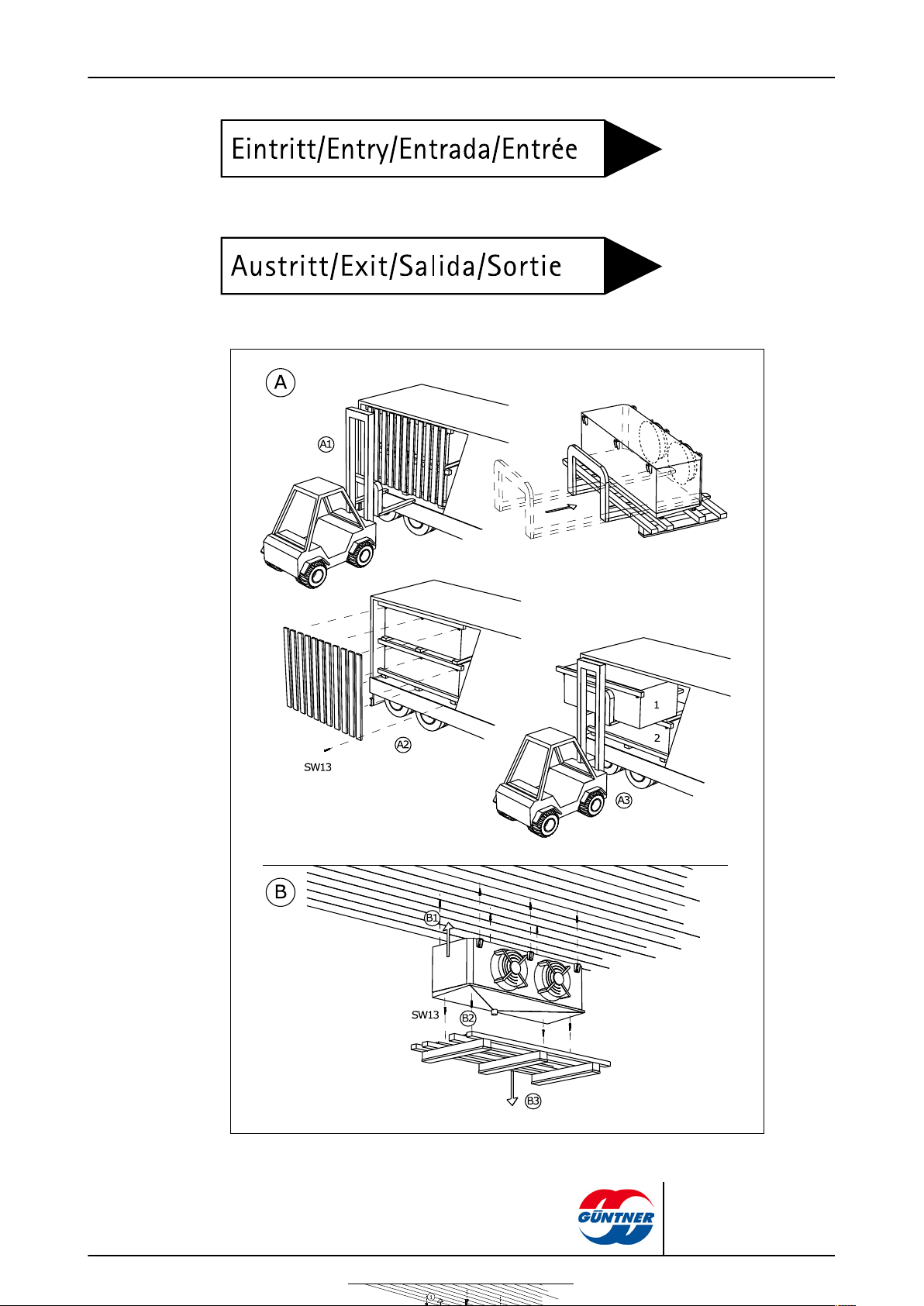
CAUTION: When transporting with a forklift: Only lift the packed unit with a forklift with full fork
length.
GGBK | 2010-09
© Güntner AG & Co. KG
Page 32

6.3 Storage before installation
Danger of corrosion and dirt build-up!
Moisture and dirt must be prevented from entering the unit.
Protect the unit against dust, dirt, moisture and wetness, damage and other harmful effects.
Harmful effects: see Safety instructions for set-up and start-up, page 33
Do not store the unit for longer than necessary. Only store the units in their original packaging
until installation. Always only place packaging units of the same size on top of one another.
Store the unit at a protected place free of dust, dirt, moisture and damage-free until its set-up
(well-ventilated halls or roofed storage site).
If the unit set-up is delayed with regard to the planned installation time: protect the unit against
weather and other harmful effects and dirt and other contaminants with an appropriate cover.
The unit must also be well-ventilated here.
page 32 / 61
NOTICE
GGBK | 2010-09
© Güntner AG & Co. KG
Page 33

7 Set-up and start-up
7.1 Safety
7.1.1 Safety instructions for set-up and start-up
WARNING
Danger of injuries and damage to property with escaping coolant!
Incorrect installation causes the danger of working fluid escaping when the unit is operated and
injuries or damage to property (see Residual hazards with the coolant/glycol, page 20).
Follow the set-up instructions in this chapter precisely and apply extreme care!
NOTICE
Damage to the system's cooling equipment!
Foreign materials and contaminants in the working fluid circuit can impair the effectiveness or
damage components. Particularly harmful contaminants are:
page 33 / 61
– Moisture
– Atmospheric air
– Welding and soldering residues
– Rust
– Soot/ash/cinders
– Metal cuttings
– Dust and dirt of all kinds
Moisture in the working fluid-carrying components of the unit can have the following consequences:
– Ageing and coolant decay
– Changes to the coolant's prescribed concentration value and setting equal an increased dan-
ger of insufficient frost protection filling in the air cooler resulting in possible unit destruction
at minus temperatures
Atmospheric air and other non-condensable gases can have the following consequences:
– Insufficient and uneven pressurizing of the air cooler with coolant equals a reduction in the
heat exchanger's capacity with the danger of impairing the work environment (increased illness-related staff time off, falling productivity)
– Changes to the coolant's setting equal an increased danger of insufficient frost protection fill-
ing in the air cooler resulting in possible unit destruction at minus temperatures
Contact with heavy oxidation agents (chromo-sulphuric acid, potassium permanganate, smoking
sulphuric acid, or similar) can have the following consequences:
– Strong chemical reactions (formation of toxic gases) endangering staff health, inadmissible
environmental stress and spoiling the foodstuffs to be cooled.
– Strong chemical reactions (formation of toxic gases) endangering staff health, inadmissible
environmental stress and disruption or rendering unusable of the unit technology installed in
the work or processing room.
Other contaminants can cause:
GGBK | 2010-09
– Accelerated chemical processes (decomposition)
– Mechanical and electrical faults in the in the cooling equipment/
© Güntner AG & Co. KG
Page 34

page 34 / 61
Ensure with installation (connecting the working fluid-carrying components of the unit to the
working fluid-carrying system of the installation's that internal contamination is strictly avoided.
Perform the installation with extreme cleanliness.
Finish all on-site pipe installation work before releasing the transport pressure!
Only release the transport pressure on the Schrader valve immediately before installation.
Only remove the sealing caps on the distribution and header pipe immediately before installation.
NOTICE
Danger of corrosion and dirt build-up!
Humidity and dirt may not get into the unit's interior. If humidity or dirt get into the unit's interior,
fittings and other components of the refrigeration installation can be damaged.
Protect the unit against dust, contamination, moisture and wetness, damage and other harmful influences. Harmful influences are, for example:
– Mechanical: Damages caused by impacts, objects falling on or against, collisions with trans-
port equipment, etc.
– Physical: Damages caused by close by concentrated flammable gases
– Chemical: Damages caused by contaminated atmospheres (salt, acid, chlorine, sulphur-con-
taining, or similar)
– Thermal: Damages caused by close by heat sources
Start as soon as possible with installation.
The electrical installation must only be performed by electricians in compliance with the relevant
VDE rules (or applicable national and international regulations) and the TCCs of the EPCs!
7.1.2 System-side safety requirements
The unit is a component of the cooling equipment/of an installation and can only be operated in
conjunction with these and the installation
•
All equipment required for operating the unit must be integrated into the switching and activation
equipment (complete system: cooling equipment + refrigeration system) :
– Electrics: Fans , heater rods with electric defrosting where app. (selection option),
– Working fluids: valves and fittings
– Drip water: drip water drain line
•
An emergency STOP switch that can be actuated without danger must be installed.
•
The working fluid-side and electrical connections must be available for the unit on the cooling
unit. The connections must be specified in the order-related offer documents.
•
The power supply of the fans must be provided in acc. with the specifications on the type plate
on the fan motors.
•
A switch-off device for preventing unexpected start-up (repairs switch), which separates all active conductors from the power supply (all-pole switch-off), must be provided for the fans in acc.
with EN 60204-1.
•
The fans' switch-on/off device must be secured (e.g. with a padlock) to prevent uncontrolled fan
start-up.
•
The electrical motor, repairs switch, terminal box and switching cabinet connections must be
provided in acc. with the respective connection diagrams.
•
It must be possible to shut off the unit if a leak occurs.
WARNING
GGBK | 2010-09
© Güntner AG & Co. KG
Page 35

•
People wearing ambient air-independent breathing apparatus in full protective clothing must also be able to activate all safety-relevant shut-off fittings.
•
It must be possible to activate all devices meant for diverting escaping working fluids from a
safe position.
7.1.3 Customer-side safety precautions
Danger of injuries!
The unit contains coolant (see Residual hazards with the coolant/glycol, page
20).
The unit is operated as standard with the coolant, ethylene glycol (synonyms:
ethane-1,2-diol, glycol). Prior agreement with the manufacturer is imperative
when using other brines.
Ethylene glycol is a colourless, slightly viscous, not very fluid, water-mixable,
deliquescent liquid with a sweet smell or taste.
With skin contact ethylene glycol causes slight irritation with the danger of skin
absorption; with eye contact mucous membrane irritation; with ingestion agitation with disruption of the central nervous system; with prolonged endangering
effect – fatigue, coordination disruption, unconsciousness, kidney damage.
Ignition and fire hazard! Ethylene glycol is flammable and explosive at higher
temperatures in a vapour/gaseous state. Keep ethylene glycol away from ignition sources. No smoking!
Ethylene glycol vapours are heavier than air and may flow off to rooms on a lower level. In still air there may be an increase of the ground level concentration.
With high concentrations, there is a danger of suffocation due to reduced oxygen concentration, especially at ground level.
Avoid contact with skin, eyes and clothing! Remove contaminated, soaked
clothing immediately!
There is no imminent danger for the staff. Ethylene glycol vapours are heavier than air and may flow off to rooms on a lower level. In still air there may be
an increase of the ground level concentration. With high concentrations, there
is a danger of suffocation due to reduced oxygen concentration, especially at
ground level.
Do not bring into contact with heavy oxidation agents (chromo-sulphuric acid,
potassium permanganate, smoking sulphuric acid, or similar)! Danger of strong
reactions!
Unauthorised people must not have access to the unit. When setting the unit up
it must be ensured that the coolant escaping from the unit cannot penetrate the
interior of the building or put people at risk in any other way.
Comply with the requirements of EN 378-3 for coolants, filling weight and cold
transfer systems.
Only install the unit in acc. with EN 378-1 in the commissioned configuration and
only in a set-up room that the unit manufacturer has configured the unit for.
Install the electrical equipment (for fan operation, for ventilation, for lighting and
for the alarm system) in the set-up room while observing the condensing-out of
page 35 / 61
WARNING
GGBK | 2010-09
© Güntner AG & Co. KG
Page 36

moisture and drip water formation, as well as the risk level of the coolant in acc.
with EN 378-3; section 6.
Ensure that the unit in the set-up room is not exposed to any inadmissible high
temperature effects. Effectively protect the unit against heat sources or temporary high temperatures.
Danger of environmental pollution!
•
Set up the unit so that coolant, which can escape from the unit in the event of a fault, cannot
enter water systems or sewage.
•
Operate the facility for recovering or disposing of so that the danger of a brine emission into
the environment is kept as low as possible.
•
If any spills or escapes occur, immediately absorb them with a universal binder (e.g. Chemi-
zorb®) and transfer them to the special waste in acc. with the specifications of the absorbed
substance.
7.2 Requirements at the set-up point
You will find the dimensions and weights in the order-related offer documents.
page 36 / 61
WARNING
Position the unit so that it cannot be damaged by internal traffic or transport processes.
Enable optimum unit control and accessibility:
– Place the unit so that is can be monitored and controlled from all sides at all times.
– Ensure that sufficient space is provided for maintenance.
– Ensure that all liquid-carrying components, connections and lines and all electrical connec-
tions and lines are easy to access.
– Ensure that the pipes' identification is well visible.
– Ensure that with units with electric block defrosting there is enough space for changing
heater rods.
GGBK | 2010-09
© Güntner AG & Co. KG
Page 37

7.3 Unpacking the unit
page 37 / 61
The palette then serves for lifting the unit (including mounted drip tray) when installing at the
set-up point.
Remove unit from packaging: For lifting, place fork of forklift below palette.
Caution! Danger of injuries and damage to property due to escaping working fluid!
see , page
NOTICE
Danger of corrosion and dirt build-up!
Moisture and dirt must be prevented from entering the unit.
Protect the unit against dust, dirt, moisture, wet conditions, damaging and other detrimental influences. Detrimental influences:see Safety instructions for set-up and start-up, page 33
Begin with the installation as soon as possible.
GGBK | 2010-09
© Güntner AG & Co. KG
Page 38

7.4 Installation
7.4.1 System-side requirements for stress-free installation
Prevent stresses in the unit:
°
Ensure that all fixing points have the same spacing to the fixing level.
°
Ensure that all fixing points maintain the same spacing to the fixing level under load and per-
manently.
Set up and fix units as follows: Airflow must not be impaired by obstructions.
page 38 / 61
GGBK | 2010-09
© Güntner AG & Co. KG
Page 39

page 39 / 61
GGBK | 2010-09
© Güntner AG & Co. KG
Page 40

page 40 / 61
For dimension E please refer to the order-related offer documents
The units must be installed on fixing points that are appropriate for the unit's weight and then
bolted with fixing bolts. The operator or installer of the equipment is responsible for ensuring
that the bolted connections are of an adequate strength. The following instructions must be observed when fixing the units:
– The diameter of the mounting holes have been statically determined by the manufactur-
er; the fixing bolts must be adapted accordingly. When calculating the transferring bearing
strength it is imperative to take into account the total weight of the unit (= structural weight +
weight of pipe content + additional weight, such as water, frost, ice, dirt or similar).
– The fixing bolts must be secured against loosening with an appropriate locking device.
– The fixing bolts must not be overtightened or stripped.
– All fixing bolts must be tightened equally.
Prevent the unit from shifting in its position. Fix the unit in its position. Tighten the fixing bolts
and secure then against loosening.
GGBK | 2010-09
© Güntner AG & Co. KG
Page 41

page 41 / 61
Ensure that the drip water drains correctly. Set up the unit horizontally with a sufficient slope for
the drip water run-off. The units are delivered in the installation position with mounted drip tray.
Only fix the unit to the intended fixing points.
7.4.2 Mounting the unit
Danger of injuries with escaping coolant!
In case of improper installation, leak of working fluid can occur during operation of the installation, this can lead to injuries or damage to property (see Residual hazards with the coolant/glycol,
page 20)
•
Only fix the unit to the fixing points intended for this.
WARNING
GGBK | 2010-09
© Güntner AG & Co. KG
Page 42

page 42 / 61
1 Only fix unit to fix-
ing points intended
for this
2 Lossen screw fas-
tening; remove unit
from palette
3 Remove palette
7.5 Notes on connecting the unit
Danger of injuries and damage to property caused by escaping coolant!
In case of improper installation, leak of working fluid can occur during operation of the installation, this can lead to injuries or damage to property (see Residual hazards with the coolant/glycol,
page 20).
Prevent working fluid from escaping from the unit into the environment.
•
Secure all working fluid-carrying lines against mechanical damage.
•
In areas that are used for internal traffic, only lay the pipelines to and from the unit with con-
nections and fittings that cannot be removed.
Ensure that the on-site connections do not exercise any forces upon the distribution and header
points. This can cause leaks on the working fluid connection points of the unit and on connection
points of the on-site pipe-laying.
WARNING
GGBK | 2010-09
•
Release devices to prevent liquid escapes are provided and available.
© Güntner AG & Co. KG
Page 43

7.5.1 Connecting the drain line to the drip tray
7.5.2 Connect the unit to the cooling equipment of the system
WARNING
Danger of injuries and damage to property!
Improper connection to the cooling unit of the system causes hazards:
•
Leaks result in escaping coolant (see Residual hazards with the coolant/glycol, page 20).
•
Soldering and welding work on pressurised parts can result in fires or explosions.
•
Smoking or open light can cause fires or explosions.
•
Ensure that stresses and vibrations from the system (complete system: cooling unit and re-
frigeration system), are not passed on to the unit.
•
Only lay working fluid-side connections stress-free! The on-site pipeline system must be
braced before connecting to the unit!
•
Soldering and welding work is only permitted on unpressurised units!
•
The use of open fire at the installation site is forbidden. Fire extinguishers and extinguishing
agents used to protect the equipment and the operating staff must comply with the require-
ments of EN 378-3.
page 43 / 61
Install the pipes in acc. with EN 378-1 and EN 378-3. Ensure here:
– That the pipeline installation is kept as short as possible. Use as few bends as possible, and if
bends are necessary, use big radii!
– The free space around the unit (e.g. the distance from the drip tray underside to any possibly
existing pipe systems) must be big enough to ensure there is no danger to the unit; regular
maintenance of the components must be possible, and it must also be possible to check and repair components, pipes and fittings.
– Electrical components, e.g. for fan operation, for heater rod operation with electrical defrost, for
ventilation, for illumination and for alarm system on installation site, have to be designed with regard to condensation of air humidity and droplet formation in acc. with EN 378-3; section 6.
– Observe the following when soldering:
°
All connections must be hard-soldered!
°
Caution! Use silver solder with TS < -40 °C! Ask manufacturer about solder specification if
required!
°
Avoid percussive soldering joints; use copper pipe ends that are widened on one side (capillary soldering)!
°
Prevent leaks, solder precisely and carefully!
°
Prevent overheating when soldering (danger of excessive scaling)!
°
Use shielding gas when soldering (prevent excessive scaling)!
GGBK | 2010-09
© Güntner AG & Co. KG
Page 44

7.5.3 Unit electrical connection and protection
Connect fan motors in acc. with motor connection circuit and check connection.
Provide power supply in acc. with the specifications on the fan motor's type plate:
■
The fan motors for the 450 mm and 500 mm fan diameters are operated in 1~ alternating
current.
Connect thermo contacts for motor protection.
Where required, connect electrical feeds and defrost limit sensor for the heater rods with electric
defrosting in acc. with electric connection diagram.
page 44 / 61
1 Defrost limit sensor
position (if used)
2 Electrics (fan motor,
stamp data, connection values)
Seal all electrical lines to the connection boxes in acc. with their protection class. The connection class is specified in the order-related offer documents.
NOTE! Danger of damaging! If the fusing is too high there is the danger of injuries to people
and damage to property. Max. fusing for the defrost heater rods feed: see order-related offer
documents. The supply lines must always be fused in acc. with the smallest wire cross-section.
7.6 Perform acceptance test
Danger of injuries and damage to property!
Escaping coolant can cause injuries or even death (see Residual hazards with the coolant/glycol,
page 20).
Perform the following acceptance test with an expert before starting up the unit after making important changes and after a unit swap-out.
WARNING
GGBK | 2010-09
© Güntner AG & Co. KG
Page 45

page 45 / 61
Ensure that sufficient air can be sucked in and released.
Ensure that the supply feed is sufficient for the required energy. Compare the unit inside of
the system(complete system: cooling equipment + refrigeration system) with the plans of the
system(complete system: cooling equipment + refrigeration system) and the electrical wiring diagrams.
Test the unit for vibrations and movements that can be caused by the fans and operation of the
system (complete system: cooling equipment + refrigeration system). Remove oscillations, vibrations and movements following consultation with the manufacturer or independently.
Perform visual inspection of the structural design, the brackets and fixtures (materials, sequence, connections), the ability to operate and the arrangement of the fittings.
Check and re-tighten all threaded connections, especially on the fans.
Check installation of pipe connections.
Check laying of working fluid-carrying connection pipes.
Ensure that the unit is protected against mechanical damage.
Ensure that the unit is protected against inadmissible heating up and cooling down.
Check the fin blades protection.
Ensure that optimum unit control and accessibility are guaranteed.
– Is the unit placed so that it can be monitored and controlled from all sides at all times?
– Is sufficient space provided for maintenance?
– Are all liquid-carrying components, connections and lines and all electrical connections and
lines easy to access?
– Are the pipes easy to identify?
Check heat exchanger surfaces for dirt and clean as required (see Clean unit, page 55).
Perform function tests on the fans (rotation direction, power consumption, etc.).
Check the soldering and welding connections, the electrical connections and the fixture connections.
Perform pressure test with test gas and with a test pressure of 1.1-times the permissible operating pressure: check the connection seals and detect leaks, e.g. with foaming agent, or similar.
Check corrosion protection: Perform a visual inspection on all bends, components and component holders that are not heat-insulated. Document and archive test results.
Perform test run. Observe and check unit during test run, in particular for:
– Fan smooth running (bearing noises, contact noises, imbalances, etc.).
– Fan power consumption:
– Leaks
Report all defects to the manufacturer immediately. Remove defects following consultation with
the manufacturer.
Check the unit and the unit's interaction with of the system(complete system: cooling equipment
+ refrigeration system) again after 48 operating hours, especially on the connections and on the
fans, and document the test results.
GGBK | 2010-09
© Güntner AG & Co. KG
Page 46

7.7 Test readiness for operation
Ensure that all electrical protective measures are ready to function.
Ensure that all working fluid-carrying connections are securely in place.
Ensure that all electrical connections (fans , if applicable heater rods for electrical defrost ) are
effected securely.
Ensure the all connections of the unit to the condensation water drain pipe are correctly installed
(see Connecting the drain line to the drip tray, page 43).
7.8 Putting the unit into operation for the first time
WARNING
Danger of injuries and damage to property!
Escaping coolant can cause injuries or even death (see Residual hazards with the coolant/glycol,
page 20).
Only put the unit into operation, when:
page 46 / 61
•
the units has been properly mounted and connected (see Installation, page 38),
•
You have performed a complete acceptance test (see Perform acceptance test, page 44).
•
You have performed a test for ensuring the system's readiness for operation (see Test readi-
ness for operation, page 46) and
•
all safety precautions (see Safety, page 33) have been taken.
Follow the operating instructions manual of the system!
Contact the manufacturer immediately if you want to operate the unit under different operating
conditions as those defined in the order-related offer documents.
Switch on the system and cooling equipment including of the electrical system (see system).
Activate the unit:
– Open the valves on the inlet and outlet-side of the cooling unit of the system.
– Activate fans
– Put drip water waste line into operation
Wait until the operating point is reached. After the operating point is reach the unit is ready to
operate (see system).
Parameters for setting the operating point, see order-related offer documents. Operating point:
•
Coolant flow temperature
•
Coolant return temperature or circulating coolant volume
•
Airflow volume
•
Air inlet temperature
•
Relative air humidity
To ensure the specified operating point is complied with the actuators for the operating point setting
must be secured against unauthorized access (e.g. by sealing, screwing on caps, removing hand
wheels, etc.).
GGBK | 2010-09
© Güntner AG & Co. KG
Page 47

8 Operation
8.1 Safety
Danger of cutting off, pulling in!
Danger of frostbite/burning!
page 47 / 61
WARNING
There is a danger of cutting off fingers on the rotating fan blades, injury hazard
for the hands and pulling in danger with loose elements such as hair, necklaces
or clothing parts.
Do not operate fans without guard grille!
WARNING
Danger of frostbite or burns if the parts are touched (see Thermal residual haz-
ards, page 20).
Do not touch any parts of the unit without protective gloves when the unit is in
operation or if it has not yet warmed up or cooled down after operation.
8.2 Putting the unit into operation
To operate the unit the system(complete system: cooling unit + refrigeration system) including
the electrical system must be in operation. The unit must be started up by opening the respective
valves on the inlet and outlet-side of the cooling equipment/of the plantby connecting to the electrical system and the drip water waste line as follows (see system operating instructions manual):
Switch on electrical system
Open working fluid-carrying lines
Switch on fans
GGBK | 2010-09
Put drip water waste line into operation
© Güntner AG & Co. KG
Page 48

8.3 Taking the unit out of operation
The units are system component parts of an refrigerationg installation (entire system: cooling + refrigeration installation). The unit is taken out of operation by switching off the cooling equipment of
the system in acc. with the refrigeration system operating instructions manual for the entire installation. To do this, the working fluid-carrying lines must be shut off from the cooling equipment of the
system and the fans, and, if applicable, the heater rods for electrical defrost, must be disconnected
from the electrical system (see operating instructions manual ):
Switch fans off
Switch electrical system off
Close working fluid-carrying lines
NOTE! When shut down consider max. operating pressure! If necessary, take precautions so
that it cannot be exceeded.
With shutdown times of a month or longer put the fans into operation for approx. 2-4 hours a
month to maintain their functionality.
page 48 / 61
NOTICE
8.4 Shutting the unit down
Danger of injuries and damage to property!
Escaping coolant can cause injuries (see Residual hazards with the coolant/glycol, page 20, and
see Residual hazards caused by pressurised parts, page 22).
Ensure that the maximum operating pressure is not exceeded after the shutdown either!
Danger of corrosion and dirt build-up!
Moisture and dirt must be prevented from entering the unit.
Protect the unit against dust, dirt, moisture, wet conditions, damaging and other detrimental influences (see Safety instructions for set-up and start-up, page 33).
With shutdown times of a month or longer put the fans into operation for approx. 2-4 hours a
month to maintain their functionality.
Take the unit out of operation (see Taking the unit out of operation, page 48).
Secure the unit:
– When shutdown consider max. operating pressure (see Technical data, page 26)! If neces-
sary, take precautions so that it cannot be exceeded.
– Secure the fan motor drives and, where applicable, the heater rods with electric defrosting
against switching on again.
– Secure working fluid-carrying lines against pressurizing with working fluid.
– Secure unit against detrimental influences at the installation or storage location (see Safe-
ty instructions for set-up and start-up, page 33) in order to keep all unit components in good
state for proper use and to conserve the usability of the unit. For this purpose, special stor-
WARNING
NOTICE
GGBK | 2010-09
© Güntner AG & Co. KG
Page 49

age conditions (see Storage before installation, page 32) and preventive measures for corro-
sion protection have to be provided, regular testing of the functionality of the fans and of the
unit taken out of operation have to be effected.
Drain the unit: Completely release coolant (see Residual hazards with disposal, page 25).
8.5 Putting the unit into operation after a shutdown
The unit must be put back into operation after a shutdown in acc. with the complete system-specific
set-up (complete system = cooling equipment + refrigeration system) in acc. with the operating instructions manual as follows:
Test the unit's readiness for operation (see Test readiness for operation, page 46). Perform
pressure test and visual inspection for corrosion protection.
NOTE! The pressure test with recommissioning must only be carried out with appropriate media at appropriate test pressure.
Put the unit into operation (see Putting the unit into operation, page 47).
8.6 Changing the unit over to another working fluid
page 49 / 61
WARNING
Danger of injuries and damage to property!
Considerable dangers can be caused with operation with another working fluid without prior manufacturer approval (Improper use).
The unit must not be changed over to another working fluid without prior written consent by
Güntner AG & Co. KG.
Ensure that the unit manufacturer has agreed to the changeover.
Ensure that the right working fluid is re-filled. Ensure that all materials used in the unit are compatible with the new working fluid.
Ensure that the permissible pressure is not exceeded.
Check that the new working fluid can be used without requiring a new test certificate for the unit.
Ensure that classification is complied with.
The safety device for the unit must be swapped out or reset.
Mixtures with residues of working fluid , for example, must be prevented.
All information concerning the new working fluid must be changed accordingly.
The complete documentation, including these operating instructions and the system operating
instructions manual must be changed accordingly.
Perform acceptance test (see Perform acceptance test, page 44).
GGBK | 2010-09
© Güntner AG & Co. KG
Page 50

9 Troubleshooting
9.1 Safety
Danger of injuries and damage to property!
Faults that are not described in these operating instructions must only be removed by Güntner.
Contact the Güntner hotline.
Faults that are described in these operating instructions must only be removed by appropriately
trained personnel (see Personnel, care requirements, page 16).
With faults that occur during the operation, monitoring and maintenance of the complete system,
inform Güntner AG & Co. KG immediately.
9.2 Service
Office hours
page 50 / 61
WARNING
Tel. +49 8141 242-473
Fax. +49 8141 242-422
Email: service@guentner.de
Mon-Thurs: 7.30 am - 5 pm
Fri: 7.30 am - 1.30 pm
9.3 Troubleshooting table
Fault Possible cause(s) Remedy
Power supply interrupted Restore power supplyFan motor not
running
Bearing noises Defective fan motor Renew bearing or fan motor
Unit capacity
not achieved
Fan blade stuck Enable fan to rotate freely
Defective fan blades Change fan bladesUnit vibrating
Loose fan fixture Tighten fixtures
Coil is strongly contaminated with
dirt
Fans not running properly or down Repair, swap out fans
Working fluid pressurising defective
(temperature and quantity insufficient)
Clean, defrost heat exchanger
Set working fluid pressurising values (temperature and quantity) to
reference values.
GGBK | 2010-09
Working fluid
escaping
Unit working fluid-carrying components leaking
Switch off working fluid feed and
fans, close leak
© Güntner AG & Co. KG
Page 51

10 Maintenance
10.1 Safety
10.1.1 Before starting all maintenance
Danger of injuries and damage to property with escaping working fluid (see Residual hazards with
the coolant/glycol, page 20)!
Only perform maintenance work – especially welding work – on the leaking unit after completely
removing the working fluid from the leaking unit!
Perform the following safety measures before beginning all maintenance work:
■
Evacuate the unit's heat exchanger
■
Clean and blow out the unit's heat exchanger.
10.1.2 With all maintenance work
page 51 / 61
WARNING
WARNING
Danger of injuries and damage to property with escaping working fluid! see Residual hazards
with the coolant/glycol)!
Escaping working fluid with leaks on the unit can cause the following hazard situations and injuries:
Warning against explosion-risk and fire-risk substances in the set-up room!
Unintentionally carried in working fluid residues can ignite. Ensure that there is
no unintentionally carried in working fluid residue in the set-up room .
Keep the risk area free of direct and indirect ignition sources.
Before releasing for maintenance for the unit obtain the required approvals for
work that can involve ignition sources (e.g. grinding, welding, soldering, etc.).
With all work involving ignition sources (e.g. grinding, welding, etc.) in the work
area, keep suitable fire extinguishing equipment that meets the requirements of
EN 378-3 at hand.
Do no bring any open flames or hot gases (e.g. candles, matches, welding
beads, welding sparks, glowing cinders or tobacco) into the set-up room.
Ensure that there are no warmed up or hot surfaces (e.g. heaters, hotplates,
bulbs, motor housings) in the set-up room.
Ensure that no friction heat develops in the set-up room (e.g. overheated
stores).
Warns against toxic and health-endangering irritants in the set-up room!
Still present coolant can evaporate and cause harmful to health irritations and
lack of oxygen.
Escaping coolant liquid must not reach adjacent rooms, staircases, yards, passages or drainage systems.
Use respiratory protection.
GGBK | 2010-09
© Güntner AG & Co. KG
Page 52

page 52 / 61
Use a room air-independent breathing apparatus with maintenance work in high
refrigerant concentrations in the room air.
Ensure the set-up room is well ventilated.
Divert escaped coolant liquid safely.
Warns against cold!
Still present coolant has a temperature of ±0 °C. Contact with coolant caused by
spraying causes frostbite/frostbite
•
Use eye protection!
•
Use hand protection!
•
Ensure that the unit in question is pressure-free before maintenance work begins or the working fluid is sucked up from the unit in question.
•
Power off the electrical system and secure it against unintentional switching on again.
•
Separate the unit to be maintained from the of the system and secure it.
Danger of damage to property!
With work in the inlet and outlet feeds of the fans and heat exchanger, objects
can get into the fans and therefore cause faults and damage on the components.
•
Power off the fans before beginning maintenance work and secure them
against switching on again.
•
After the work has finished do not allow any objects to get back into the inlet
and outlet feeds of the fans or the set-up room.
10.1.3 After all maintenance work
Danger of injuries and damage to property caused by escaping coolant (see Residual hazards
with the coolant/glycol, page 20)!
NOTICE
WARNING
GGBK | 2010-09
Perform the following safety measures after finishing all maintenance work:
•
Ensure the switching and activation devices, the measuring and display devices and the safety devices function properly.
•
Ensure the working fluid fittings are functioning.
© Güntner AG & Co. KG
Page 53

•
Ensure that the swivel fan units (optional) and the hinged side covers are fixed in their original
position and secured against unintentional or unauthorised opening.
•
Check the identification of the pipelines and ensure this is visible and legible.
•
Check the fixing and corrosion protection of the components in question.
•
Ensure the electrical connections (fans and, where applicable, the heater rods with electric defrosting) are functioning.
•
Ensure the temperature and air humidity at the set-up point are the same as that in the order-related offer documents.
•
Perform a pressure test and a tightness test (see operating instructions manual annex).
•
Perform an acceptance test (see Perform acceptance test, page 44).
•
Perform a pressure test (see operating instructions manual annex).
10.2 Inspection and maintenance plan
10.2.1 Fans
The checks to be performed are listed in the following sections as time-scaled checklists.
The manufacturer's operating specifications take priority for this component. Güntner AG & Co KG
recommends proceeding in acc. with the following inspection and maintenance plan:
page 53 / 61
d = daily, w = weekly, m = monthly, y = yearly
Work to be performed d w m y
Check fans for dirt, frost and ice build-up.
•
With dirt build-ups: Clean fans (see Clean unit, page 55)
•
With frost and ice build-ups: Defrost the unit (see Defrosting the
unit, page 58).
Check the fan drive for smooth running.
•
Vibrations on the unit: remove imbalances
•
Where required, tighten and correct blade fixtures and blade settings
Fan bearing: Running sound and smoothness changes
•
Swap out bearing
Fan motor: Is a new bearing due?
•
Swap out bearing or motor; where applicable, clean and repair
motor
Fan wheel: corrosion on bolts (with threaded blades)
•
Swap out bolts
Fan blades: Corrosion or damage on blades
•
Swap out blades or wheel
X
X
X
X
*
X
*
X
*
*) Recommended: every six months
10.2.2 Unit heat exchanger
Danger of injuries and damage to property caused by escaping coolant(see Residual hazards with
the coolant/glycol, page 20)!
GGBK | 2010-09
WARNING
© Güntner AG & Co. KG
Page 54

page 54 / 61
d = daily, w = weekly, m = monthly, y = yearly
Work to be performed d w m y
Check heat exchanger for dirt, frost and ice build-up.
•
With dirt build-ups: Clean heat exchanger (see Clean unit, page
55).
•
In case of frost or ice build-up: Defrost unit (see Defrosting the
unit, page 58).
Check heat exchanger's general condition.
•
Damages found: remove damages
Check heat exchanger's operating point (see Operation, page 47).
•
Change in fan capacity found: restore required system-side conditions .
•
Change in surface temperatures found: restore required system-side conditions .
Check heat exchanger and connections for tightness.
•
Repair affected unit part (see Remove leaks, page 55).
Check heat exchanger for working fluid pressurising.
•
Restore required cooling unit-side conditions.
Check heat exchanger for corrosion.
•
Corrosion or damage on core tubes, fins, support structures, tube
connections, fixtures: repair unit sections affected.
*) recommended: every six months
X
X
X
X
*
X
X
*
Care and maintenance plan
Measure Cleaning agent Interval
Remove frost and clean
component
Heat exchanger defrosting Circulation air, electric,
Complete cleaning Warm water or environmen-
Leak check After 6 months
Corrosion protection check After 6 months
Mechanically As required (visual inspec-
tion)
According to local conditions
; automatic defrosting device;
tally safe cleaning agent
(penetrating moisture (air
or chilled oods , personnel,
processed goods); with an ice
thickness of 1 mm at the lat-
est
After 120 hours
GGBK | 2010-09
© Güntner AG & Co. KG
Page 55

10.3 Maintenance work
ACHTUNG - ATTENTION - ATTENTION - ATENCIÓN
Bei der Verwendung von
Reinigungsmitteln in
Kühlräumen, ist auf die
Korrosionsbeständigkeit
der Materialien des
Kühlers gegenüber dem
verwendeten Reinigungsmittel zu achten!
When cleaning agents
are used inside the cold
room, the corrosion
resistance of the cooler
materials to the applied
cleaning agent has to be
observed!
Lors de l‘utilisation des
détergents dans les
chambres froides, il faut
observer à la résistance à
la corrosion des
matériaux de l‘appareil
qui entrent en contact
direct avec les
détergents.
Cuando se apliquen
agentes limpiadores en
los productos instalados
en cámaras frías, se
debe tener cuidado que
no corroen los
materiales usados para
la construcción del
producto!
10.3.1 Remove leaks
Danger of injuries with coolant (see Residual hazards with the coolant/glycol, page 20)!
•
Have leaks removed as quickly as possible by an expert.
•
Do not fill with a working fluid other than that specified in acc. with the order-related offer documents!
•
Only put the unit back into operation when all leaks have been repaired.
Perform all work including pressure, acceptance and functional test (see Perform acceptance
test, page 44, and see Test readiness for operation, page 46).
10.4 Clean unit
10.4.1 General
The following applies for cleaning: The operator must ensure that the cleaning agent is environmental friendly. Harmful to the environment substances, e.g. acid-forming, are forbidden.
page 55 / 61
WARNING
Clean casing by rinsing with warm water (approx. +25°C) and/or with environmentally friendly
cleaning agents.
Rinse thoroughly with water after using cleaning agents.
Allow casing to dry completely.
Check working fluid-carrying and electrical connections (see Test readiness for operation, page
46).
10.4.2 Clean and defrost heat exchanger
GGBK | 2010-09
Drain the unit (see system).
Shut off the unit (see system).
Power off the fans (see system).
Perform defrosting (see system).
© Güntner AG & Co. KG
Page 56

page 56 / 61
Clean the heat exchanger with one of the following procedures:
– Cleaning with compressed air (see Cleaning with compressed air, page 56).
– Hydraulic cleaning (see Hydraulic cleaning, page 56)
– Cleaning with brushes or brushes and compressed air (see Cleaning with brushes or brush-
es and compressed air, page 57).
NOTICE
Danger of damage to property!
The fins can be damaged with too high a pressure, too small a distance or a cleaning jet that hits
the fins at an angle. Mechanical cleaning with hard objects (e.g. steel brushes, screw drivers, or
similar) damages the heat exchanger.
•
Use a pressure of max. 50 bar with hydraulic cleaning and max. 80 bar with cleaning with compressed air!
•
Maintain a minimum distance from the fins of 200 mm!
•
Always aim the jet vertically (max. ±5 degree deviation) at the fins!
•
Do not use any hard objects when cleaning!
Switch fans on (see system).
Open coolant return line (see system operating instructions manual).
Open working fluid feed (see system).
10.4.2.1 Cleaning with compressed air
Blast heat exchanger (max. 80 bar pressure) with compressed air to remove dirt and contaminants.
NOTE! Hold the jet of the cleaner vertical to the fins (max. deviation of ±5 degrees) to prevent
fins from bending.
10.4.2.2 Hydraulic cleaning
Warns against dangerous electrical voltage!
Direct and indirect contact with voltage-carrying parts of motors and electrical
lines can cause serious injuries or death. Water and cleaning agents conduct
electricity.
•
Power off the fans for cleaning with water or steam jet and where applicable
the heater rods for electrical defrost and ensure them against switching on
again.
WARNING
GGBK | 2010-09
NOTICE
Danger of damage to property!
Water or steam jets can damage fans, electrical lines or other components.
•
Ensure that electrical connections and motors, as well as components and stored goods at
the set-up point are not touched by water or steam jets. Cover these if required.
© Güntner AG & Co. KG
Page 57

page 57 / 61
Heavier moisture or greasy dirt must be removed with a high-pressure water jet (max. 50 bar
pressure), steam pressure jet (max. 50 bar pressure), min. 200 mm distance with flat jet nozzle,
or using neutral cleaning agent where applicable, always against the airflow direction. Ensure
here:
– With oily and greasy dirt it helps to add a cleaning agent to the water.
– When applying chemical agents ensure that they are not aggressive towards the unit's mate-
rials. Rinse the unit off after the treatment.
– Cleaning should be done from inside to the outside (but always opposing the dirt onset) and
from top to bottom, so that the dirt can be removed without returning.
– Hold the jet of the cleaner vertical to the fins (heat exchanger – max. deviation of ±5 de-
grees) to prevent fins from bending.
Continue cleaning until all dirt has been removed.
10.4.2.3 Cleaning with brushes or brushes and compressed air
Remove dry dust or dirt with a brush, a hand brush or with compressed air (max. 80 bar pressure, min. distance of 200 mm to the fins; against the airflow direction) or with a powerful industrial vacuum cleaner. Ensure here:
– Use soft brushes (no steel brushes or similar)!
– Where possible, cleaning should be from the top down. Where possible, cleaning should
be from top to bottom, so that the dirt can be removed without the possibility of returning to
cleaned parts. Continue cleaning until all dirt has been removed.
– Always brush the fins lengthways – never across!
10.4.3 Cleaning fans
WARNING
Danger of cutting off, pulling in!
There is a danger of cutting off fingers on the rotating fan blades, injury hazard for the hands and
pulling in danger for loose elements such as hair, necklaces or clothing parts.
GGBK | 2010-09
© Güntner AG & Co. KG
Page 58

page 58 / 61
•
Power off the unit before you begin maintenance work. Secure the unit against unintentional
switching on again by removing the electric fuses for the unit. Secure the unit with a suitable
warning sign referring to unintentional switching on.
•
Put fans and guard grilles that were removed or opened for maintenance back into their original status without fail before you put the unit back into operation!
Dirt build-ups and frost and/or icing on the fans and the fan guard grilles must be removed regularly,
otherwise they will cause imbalances or destruction and power losses. The fan motors themselves
are maintenance-free.
Power off the unit and secure it against unintentional switching on.
Clean fans with one of the following procedures:
NOTE! Danger of damage to property! Mechanical cleaning with hard objects (e.g. steel brushes, screw drivers, or similar) damages the fan. Forbidden!
– Cleaning with compressed air: Blow fans with compressed air (max. 10 bar pressure; min.
distance 200 mm) to remove dirt and contaminants. Continue cleaning until all dirt has been
removed.
– Cleaning with compressed air and brushes: Remove dry dust or dirt with a brush, a hand
brush or with compressed air (max. 10 bar pressure, min. distance of 200 mm) or with a
powerful industrial vacuum cleaner. Ensure here: use soft brushes (no steel brushes or similar)! Continue cleaning until all dirt has been removed.
Mount guard grille
Switch unit on
10.5 Defrosting the unit
10.5.1 Notes on defrosting
Defrosting the unit at the correct times guarantees continuous operational reliability and the prevention of inaccessibilities that could result in a shutdown and disruptions. As the local conditions have
a very big influence of the unit's performance and the need for defrosting, the operation must be
checked regularly and specifically for frost and/or icing on the heat exchanger. The following notes
apply for defrosting the unit:
•
Regular checks for frost and/or icing. With a frost thickness of max. 1 mm per fin side the unit
must be defrosted to be able to guarantee fault-free operation.
•
Defrosting process must start in good time.
The frequency of defrosting depends on the amount of entering (e.g. through door of cold room) or
inserted (e.g. personnel, processed goods ) humidity. In this regard, it has to be observed that the
temperature difference between working fluid and air inlet temperature determines the frequency of
defrosting:
•
Unit with greater temperature difference: Frequent defrosting
•
Unit with lesser temperature difference: Less defrosting
Also changing operating states such as e.g. changes of use at the installation site have to be observed. The defrost frequency can also be influenced by effects on the air side: Insufficient distance
between wall and unit, insufficient distance between two units, supporting architectural elements
close to air outlet can leed to increased defrost frequency.
GGBK | 2010-09
© Güntner AG & Co. KG
Page 59

Defrosting completeness
When finishing the defrosting process you must ensure that the defrosting is absolutely complete.
Selecting the right defrosting temperature is an important requirement in this respect.
•
If the defrosting temperature is set too low this impairs the unit's effectiveness from one defrost-
ing to another with the removal of "ice-spots".
•
If the defrosting temperature is set too high this causes extreme water vapour formation, which
causes frost and ice to form around the unit.
Settling time
A period (approx. 5 to 8 minutes) between when the defrosting finishes and when the unit is activated has been proven to be necessary, as the unit's heat exchanger can drip off completely and the
defrosting water can flow away through the drip water tray drain during this period.
Delayed fan start
If the fans' activation is delayed by a further period (approx. 3 to 5 minutes), then the defrosting
heat from the heat exchanger is absorbed and it is not given off into the room as warm-moist air.
page 59 / 61
10.5.2 Defrost control
Electrical defrost
•
The defrosting process is started at pre-set intervals or as required.
•
The process completion must be ensured twice (time/temperature and temperature/tempera-
ture),
•
For defrost operation (air, electrical), the correct installation by customer of the defrost sensor
has to be observed. See defrost procedures listed below.
•
Recommendation – perform the defrosting process at the following times:
Cold operation X
Suction operation 5 min.
Defrost operation Approx.
Drip phase 5 min.
Freeze on phase 5 min.
Cold operation X
Fans Opera-
tion
Operation
50 min.
Off Off Off Opera-
tion
10.5.3 Circulation air defrosting
GGBK | 2010-09
When operating units at room temperature in the positive range (cooling rooms above freezing
point / working / processing rooms) and evaporating temperatures t0 = 0 up to -5°C, the air circula-
tion defrost is sufficient in most cases: With locked working fluid-carrying lines the required defrost
heat is generated by the fan heat and the air temperature in the positive range. But also here the
following applies: Only after having entirely completed the defrosting procedure, the refrigerating
operation, as described, can be started again.
© Güntner AG & Co. KG
Page 60

10.5.4 Electric defrosting
With several units per room with electric defrosting alternating defrosting should be avoided, as otherwise reciprocal influences can have a negative effect here. These influences result on one hand
from the extraction of the heat from the units to be defrosted and therefore in a defrost delay, and
on the other hand in an additional stress with heat and moist air on the units in refrigerating operation. Group defrosting is recommended instead of alternating. Several units are grouped here into
a defrosting group. If a group is now defrosted, the other groups must be switched off. This means
that with a temperature increase in the room, which is not above the alternating defrosting one, the
reciprocal influencing of the units is limited to a minimum, as described above.
The following must be ensured here: With alternating defrosting within a room (group defrosting),
use defrost closure devices (defrost flaps, textile closure devices)! An on-site monitoring with a
safety device (temperature limiter; to be planned for in creating the annex) must be provided in acc.
with EN 60519-2; VDE 0721; T. 411 to rule out the danger of the units overheating. Operation without a temperature monitor is forbidden! The max. permissible fuse for the electric heating groups
with 20 A must be complied with without fail. The min. fusing is provided in the order-related connection diagrams. To prevent the permissible pressure in the unit from being exceeded with electric
defrosting systems, in acc. with EN 378-2 either working fluid displacement must be enabled or a
suction circuit must be provided.
A separate control of the coil and tray defrosting is possible (see note in electric connection plan).
page 60 / 61
10.5.5 Further notes on defrosting
The drains of the drip trays must be heated (apart from plus-cold storage rooms), so that ice formation is prevented here.
GGBK | 2010-09
© Güntner AG & Co. KG
Page 61

page 61 / 61
11 Plans/diagrams
11.1 Electrics documentation
11.1.1 Fan motor connection diagram
11.1.2 Connection diagram electrical defrost (selectable option; accessory on customer request)
11.2 Working fluidconnection diagram
See motor terminal box cover inside on the fan.
See order-related offer documents
See order-related offer documents
GGBK | 2010-09
© Güntner AG & Co. KG
 Loading...