

FY Union FY-212H, FY-3208G Operation Manual
1
Operation Manual
Thank you very much for purchasing FY series printer
15 June 2009
Version : 2.0
● In order to use FY series printer correctly and safely and understand this product’s capability,
please read through this manual.
● This manual includes equipment structure, description, technical parameters, operation manual,
safety information, application of software, etc.
● This manual is subject to change without notice.
● Contents herein contained are believed to be correct, however, please contact us if you find any
error or something not clear enough.
●Copyright 2009 FY Union. All rights reserved.
FY-212H

2
Table of Contents
Chapter 1: Safety Precaution…………………………………….… 3
Chapter 2: Preparation and Procedures for Assembling………5
Chapter 3: Machine Structure and Accessories…………………8
Chapter 4: Basic Operation………………………………….……....11
Chapter 5: Maintenance Guide………………………………………22
Chapter 6: Troubleshoot …………..…………………………………..27
Chapter 7: Technical Specification……..………………………..…..29

3
1.1 Important Safety Measures
Please read the following instructions before using the printer. Follow cautions and
instructions which are labeled on the printer.
Do NOT block the cover on the top of the printer.
Do NOT insert any object into the printing platform of the printer. Prevent spilling liquid onto
the printer.
ONLY 220V can be applied.
Connect all the power cord to a single socket extension. Avoid sharing the socket with other
devices which will be on and off frequently.
Avoid using the socket with self-timer control and with the switch on the wall.
Keep a distance from any device which may release electro-magnetic field, such as wireless
phone.
Do NOT use damaged power cord.
If using an extra power cord, keep in mind that the total ampere of this device does not exceed
the assigned ampere of the power. Also, the total ampere of all device which connect to single
socket cannot exceed the assigned ampere.
Do NOT try to repair the printer.
When encounter the following circumstance, disconnect the power and contact your local
distributor for support:
Liquid is spilled onto the printer;
The printer fells down or the surface is broken;
Printer does not run normally.
Chapter 1 Safety Precaution

4
1.2 Handling Printer Caution
Do NOT move the carriage when the power is on.
Always use the power switch to turn on or off the printer. Do NOT try to remove the data cable or
the power cord when the machine is on.
Make sure the carriage is stabilized in the origin position during transport.
Do NOT touch printing platform during printing.
1.3 Handling Ink Tank Caution
Please store ink tanks at the place where children cannot reach. Do NOT let children touch the
ink tank.
If ink is spilled into eyes, immediately wash with water and see your doctor.
Do NOT shake the ink tank, this may cause leakage.
Please often check the ink content in main ink tank, avoid unnecessary loss due to lack of ink.
Please often check the waste ink tank and replace it in time when it becomes full.
1.4 Printer Installation Site
Place the printer on a level floor. If the floor is not level, adjust the support of the printer.
Avoid placing the printer in the area with huge change of temperature and humidity. Do NOT
expose the printer to direct sunlight or heat.
Avoid placing the printer in any possible shaking or vibrating area.
Leave enough space around the printer to ensure normal ventilation.
Place the printer close to the power socket so that power cord can be removed and plugged
easily.
Chapter 1 Safety Precaution

5
2.1 Environment requirement
Keep the room temperature between 20—30℃, and the humidity between 40—60%. Air
conditioner and humidifier may require. Keep a distance from strong radiation field. The floor must be
level.
2.2 Electrical requirement
The printer only supports AC 220V. A transformer is needed if the area is using AC110V.
The printer must be well grounded ( the grounded voltage shouldn’t be more than 0.3V,
and the grounded resistance should be less than 3Ω ).
UPS and voltage stabilizer is highly recommended.
2.3 Computer requirement
1) Basic requirement:
CPU: 2.0 GHz or higher
Memory: 1Gb or higher
Hard disk: 80 Gb (recommend 20Gb free space)
Mother board: PCI card slot
Network card
Operating system: Microsoft Windows (2000, XP)
2) Recommended requirement:
CPU: 3.0 GHz or higher
Memory: 2 Gb or higher
Hard disk: 200 Gb or higher (NTFS format)
Mother board: PCI card slot
Network card
Operating system: Microsoft Windows (2000, XP)
NOTE: Suggest user format your hard disk into 2 partitions (NTFS). The first partition is used for
installing OS and other software, the second partition is used to save pictures and work files.
Chapter 2 Preparation and Procedures for Assembling

6
2.4 Procedures of Assembling
1) Move the packing box to the working site and avoid strong shaking.
2) Disassemble the wooden packing box from top to bottom. Check whether the parts are
complete or not according to the packing list.
3) Lift the printer out by a forklift, and move it to the installation site.
4) Check if the printer is level.
5) Get rid of all the parts that stabilize the carriage, and install all the spare parts.
6) Move the carriage manually to the right of the printer, then move back to the left. During this
process, check if there is abnormal resistance, and carefully inspect the belt & the encoder
sensor are situated in proper position.
7) Ground the printer. The grounded voltage shouldn’t be more than 0.3V, and the grounded
resistance should be less than 3Ω .
8) Install the PCI card into the computer. Check if the wires and data cables are plugged in
properly.
9) Install the output and the rip software.
10) Turn on the printer, and keep your hand on the emergency button for turning off the printer
if problem happens suddenly.
11) Send a file to print to test the condition of the printer.
12) Clean the whole ink supply system with solvent. Then empty the ink sub-tanks, and repeat
the step twice. At last, empty the remained solvent in the ink supply tubes through ink
sub-tanks.
13) Fill the main tank with ink. Then empty the ink sub-tanks, and repeat the step twice, in order
to ensure there is no mixture of ink and solvent in the ink supply system.
14) Dip the aluminous caps in the solvent and clean them, in order to ensure no any sundries
exist.
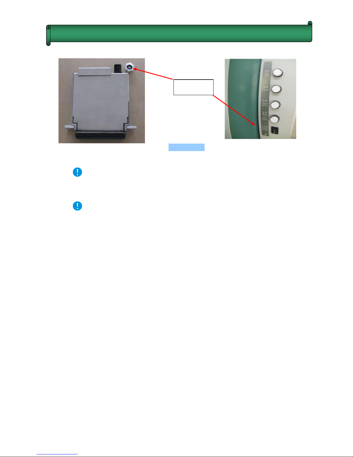
15) Turn off the printer. Take the black washer out from the white cap on the top of the damper,
and then place the washer in the aluminous cap. (Figure 2-1) Stabilize the printhead with
screws. Connect the tube, and tighten the aluminous cap at the ink incoming part on the
top of the damper. Finally, connect the data cable.
Chapter 2 Preparation and Procedures for Assembling
7
Figure 2-1
Attention A: When connecting the aluminum cap to the printhead damper, you
should screw it perpendicularly to avoid damaging the screw thread of the
damper.
Attention B: When assemble new printhead, it’s not necessary to flush the printhead
with solvent. It’s because no protective fluid remains in printhead.
16) Fill the printhead with ink by using positive pressure, And then, wipe the ink droplet on the
surface of the nozzle plate with sponge stick.
17) Print nozzle checking, and observe the condition of printheads. It is recommended to
keep a copy of the test for reference in the future.
18) Printhead alignment.
19) Start to Print.
Chapter 2 Preparation and Procedures for Assembling
Washer
8
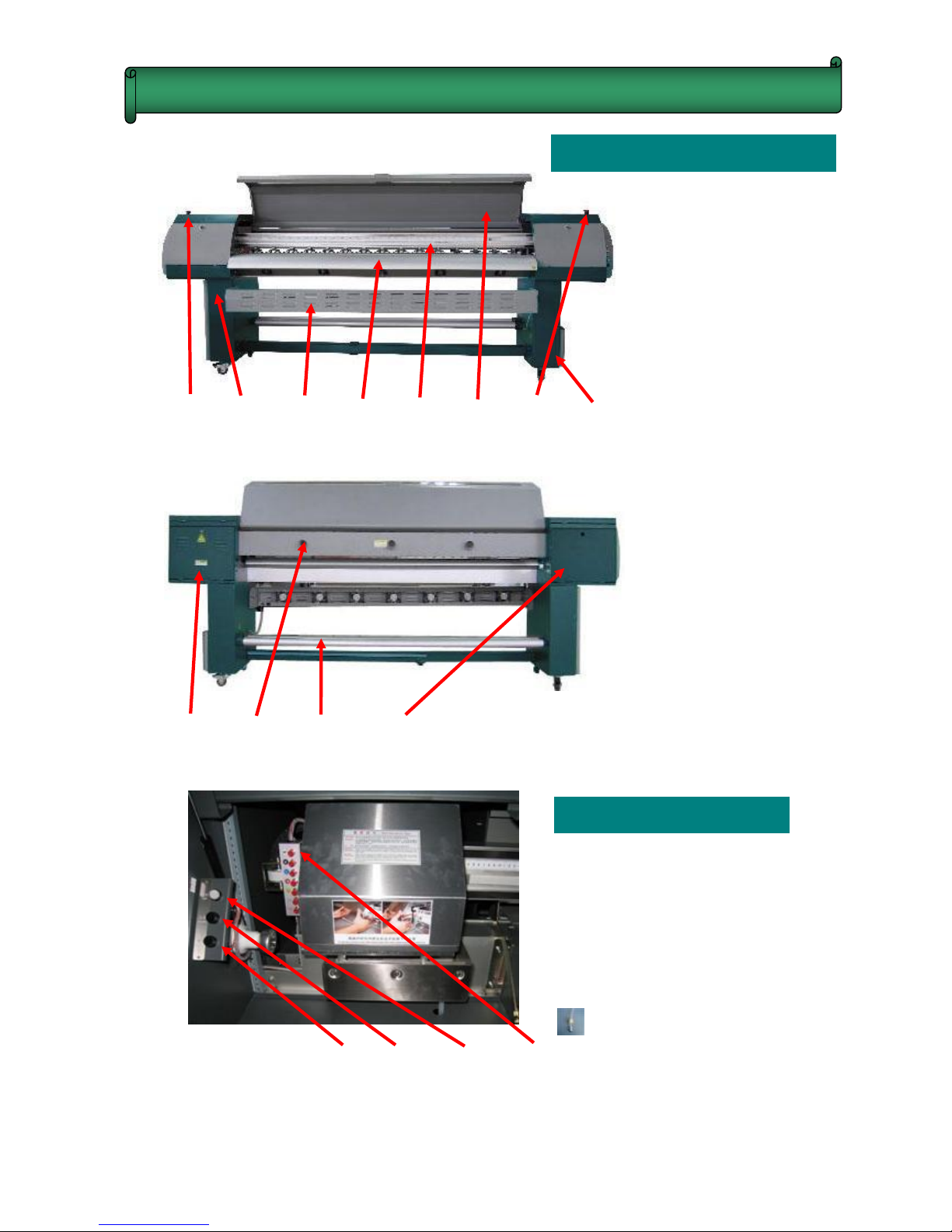
Machine Appearance
(1) (2) (3) (4) (5) (6) (7) (8)
(9) (10) (11) (12)
Cleaning Control
(13) Solvent Cleaning Switch
(14) Solvent Cleaning Switch
(15) Light Switch
(16) Individual Purging Switches
Individual Purging Switch:
“AF” is used to clean all
printheads. In addition, press
switches (13)+(14) together
to start solvent cleaning.
(13) (14) (15) (16)
(1) Left Emergency Switch
(2) Bottom Left Machine box
(3) Cooling System
(4) Printing Platform
(5) Girder
(6) Printer Cover
(7) Right Emergency Switch
(8) Bottom Right Machine Box
(9) Circuit Controlling Box
(10) Exhaust Emission
(11) Media Feeding Bars
(12) Top Left Machine Box
Chapter 3 Machine Structure and Accessories
9
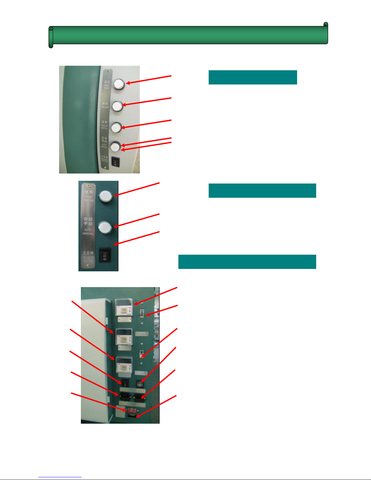
Basic Operation
(17) Printhead Voltage Switch
(18) Media Suction Switch
(19) Media Take-up Switch
(20) Automatic or Manual Mode
(21)Turning Direction Switch
Media Feeding Button
(22) Media Feeding Switch
(23) Automatic or Manual Mode
(24) Turning Direction Switch
Main Power Controlling Area
(25) Optical Fiber Interface
(26) Heater Power Socket
(27) Heater Power Switch
(28) Rear Heater Controller
(29) Middle Heater Controller
(30) Front Heater Controller
(31) Heater Safety Switch
(32) Printer Safety Switch
(33) Printer Power Switch
(34) Printer Power Socket
(35) High Density Data Cable
Interface
( 17)
( 18)
( 19)
(20)
(21 )
( 22)
( 23)
( 24)
Chapter 3 Machine Structure and Accessories
( 31 )
( 32)
( 33)
( 34 )
( 35 )
( 25 )
( 26)
( 27 )
( 28 )
( 29 )
( 30 )
 Loading...