

Page 1
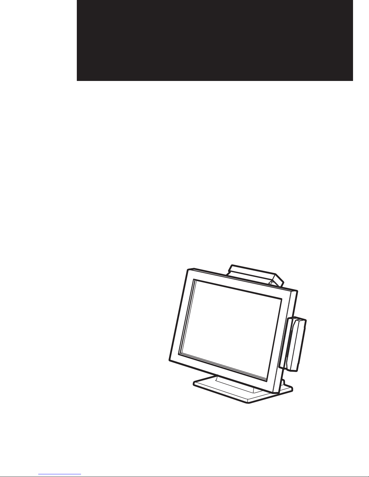
USER MANUAL
Point-of-Sale
Hardware
System
VERSION V1.4 DECEMBER 2010
Page 2

ii
Copyright 2010
All Rights Reserved
Manual Version 1.4
Part Number: 3LMPP7900214
The information contained in this document is subject to change without notice.
We make no warranty of any kind with regard to this material, including, but not
limited to, the implied warranties of merchantability and fitness for a particular
purpose. We shall not be liable for errors contained herein or for incidental or
consequential damages in connection with the furnishing, performance, or use of
this material.
This document contains proprietary information that is protected by copyright. All
rights are reserved. No part of this document may be photocopied, reproduced
or translated to another language without the prior written consent of the
manufacturer.
TRADEMARK
Intel®, Pentium® and MMX are registered trademarks of Intel® Corporation.
Microsoft® and Windows® are registered trademarks of Microsoft Corporation.
Other trademarks mentioned herein are the property of their respective owners.
Safety
IMPORTANT SAFETY INSTRUCTIONS
To disconnect the machine from the electrical power supply, turn off the power 1.
switch and remove the power cord plug from the wall socket. The wall socket must
be easily accessible and in close proximity to the machine.
Read these instructions carefully. Save these instructions for future reference.2.
Follow all warnings and instructions marked on the product.3.
Do not use this product near water.4.
Do not place this product on an unstable cart, stand, or table. The product may fall, 5.
causing serious damage to the product.
Slots and openings in the cabinet and the back or bottom are provided for 6.
ventilation to ensure reliable operation of the product and to protect it from
overheating. These openings must not be blocked or covered. The openings
should never be blocked by placing the product on a bed, sofa, rug, or other
similar surface. This product should never be placed near or over a radiator or heat
register or in a built-in installation unless proper ventilation is provided.
This product should be operated from the type of power indicated on the marking 7.
label. If you are not sure of the type of power available, consult your dealer or local
power company.
Do not allow anything to rest on the power cord. Do not locate this product where 8.
persons will walk on the cord.
Never push objects of any kind into this product through cabinet slots as they 9.
may touch dangerous voltage points or short out parts that could result in a fire or
electric shock. Never spill liquid of any kind on the product.
Page 3
iii
CE MARK
This device complies with the requirements of the EEC directive 2004/108/EC
with regard to “Electromagnetic compatibility” and 2006/95/EC “Low Voltage
Directive”.
FCC
This device complies with part 15 of the FCC rules. Operation is subject to the
following two conditions:
(1) This device may not cause harmful interference.
(2) This device must accept any interference received, including interference that
may cause undesired operation.
CAUTION ON LITHIUM BATTERIES
There is a danger of explosion if the battery is replaced incorrectly. Replace only
with the same or equivalent type recommended by the manufacturer. Discard
used batteries according to the manufacturer’s instructions.
Battery Caution
Risk of explosion if battery is replaced by an incorrectly type.
Dispose of used battery according to the local disposal instructions.
Safety Caution
Note: To comply with IEC60950-1 Clause 2.5 (limited power sources, L.P.S)
related legislation, peripherals shall be 4.7.3.2 “Materials for fire enclosure”
compliant
4.7.3.2 Materials for fi re enclosures
For MOVABLE EQUIPMENT having a total mass not exceeding 18kg.the material
of a FIRE ENCLOSURE, in the thinnest signifi cant wall thickness used, shall be
of V-1 CLASS MATERIAL or shall pass the test of Clause A.2.
For MOVABLE EQUIPMENT having a total mass exceeding 18kg and for all
STATIONARY EQUIPMENT, the material of a FIRE ENCLOSURE, in the thinnest
signifi cant wall thickness used, shall be of 5VB CLASS MATERIAL or shall pass
the test of Clause A.1
Page 4

iv
LEGISLATION AND WEEE SYMBOL
2002/96/EC Waste Electrical and Electronic Equipment Directive on the treatment,
collection, recycling and disposal of electric and electronic devices and their
components.
The crossed dust bin symbol on the device means that it should not be disposed
of with other household wastes at the end of its working life. Instead, the device
should be taken to the waste collection centers for activation of the treatment,
collection, recycling and disposal procedure.
To prevent possible harm to the environment or human health from uncontrolled
waste disposal, please separate this from other types of wastes and recycle it
responsibly to promote the sustainable reuse of material resources.
Household users should contact either the retailer where they purchased this
product, or their local government office, for details of where and how they can
take this item for environmentally safe recycling.
Business users should contact their supplier and check the terms and conditions of
the purchase contract.
This product should not be mixed with other commercial wastes for disposal.
Page 5
v
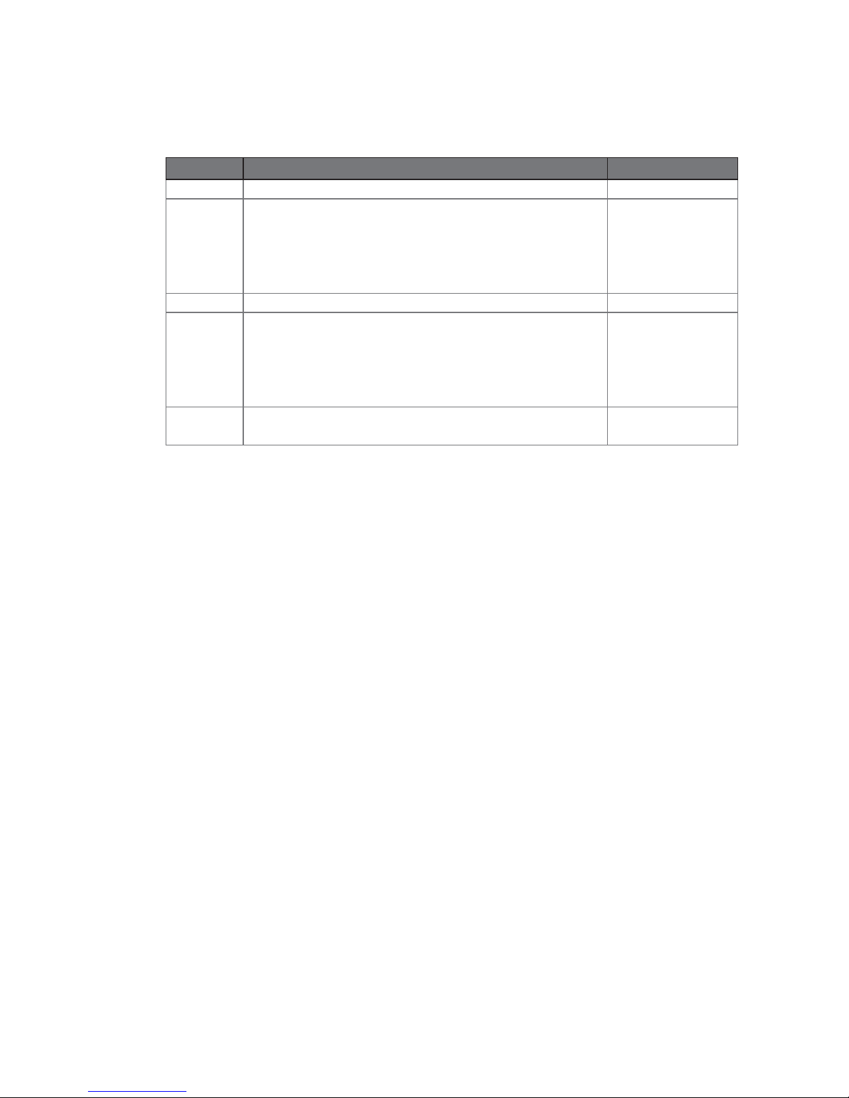
Revision History
Changes to the original user manual are listed below:
Revision Description Date
1.0 Initial release• 2007 August
1.1
Cover page update•
System View update•
System Installation update•
System Disassembly update•
Specification update •
2007 December
1.2 Performance model info. added• 2008 January
1.3
B68 motherboard Added•
B78 motherboard updated to v2.2•
B98 motherboard Added•
Format Change•
Jumper Setting updated•
2009 December
1.4
SSD Card Replacement Added•
C48 motherboard Added•
2010 December
Page 6

vi
Table of Contents
1. Packing List .............................. 1
1-1. Standard Accessories ..............................................1
1-2. Optional Accessories ...............................................2
2. System View ............................. 3
2-1. Front View ...............................................................3
2-2. Side View .................................................................3
2-3. Rear View with stand ...............................................4
2-4. Rear View without wall mount bracket .....................4
2-5. I/O Ports View ..........................................................5
2-6. System Dimension ...................................................6
3. System Assembly .................... 7
3-1. HDD replacement for fan system ............................7
3-2. HDD replacement for fanless system ......................7
3-3. RAM Replacement ..................................................8
3-4. Power Adapter Replacement ...................................9
4. Peripheral Installation ............ 10
4-1. MSR Installation .....................................................10
4-2. VFD Installation ......................................................10
4-3. Wall Mount Kit Assembly ........................................ 11
4-4. Desktop Stand Assembly ........................................12
4-5. Wireless LAN Installation ........................................13
4-5-1. On a Fan System ....................................................13
4-5-2. On a Fanless System .............................................. 14
Page 7

vii
4-6. SSD Card Replacement .........................................15
4-6-1. On a Fan System ....................................................15
4-6-2. On a Fanless System .............................................. 16
4-7. Cash Drawer Installation .......................................17
4-7-1. For B78 motherboard .............................................. 17
4-7-2. For B68/B98/C48 motherboard ............................... 19
5. Specification ........................... 21
6. Jumper Setting ........................ 23
6-1. For B68 Motherboard .............................................23
6-1-1. Motherboard Layout ................................................23
6-1-2. Connectors & Functions .......................................... 24
6-1-3. Jumper Setting ........................................................26
6-2. For B78 Motherboard .............................................29
6-2-1. Motherboard Layout ................................................29
6-2-2. Connectors & Functions .......................................... 30
6-2-3. Jumper Setting ........................................................31
6-3. For B98 Motherboard .............................................34
6-3-1. Motherboard Layout ................................................34
6-3-2. Connectors & Functions .......................................... 35
6-3-3. Jumper Setting ........................................................36
6-4. For C48 Motherboard .............................................39
6-4-1. Motherboard Layout ................................................39
6-4-2. Connectors & Functions .......................................... 40
6-4-3. Jumper Setting ........................................................41
Appendix: Drivers Installation .... 46
Page 8
1
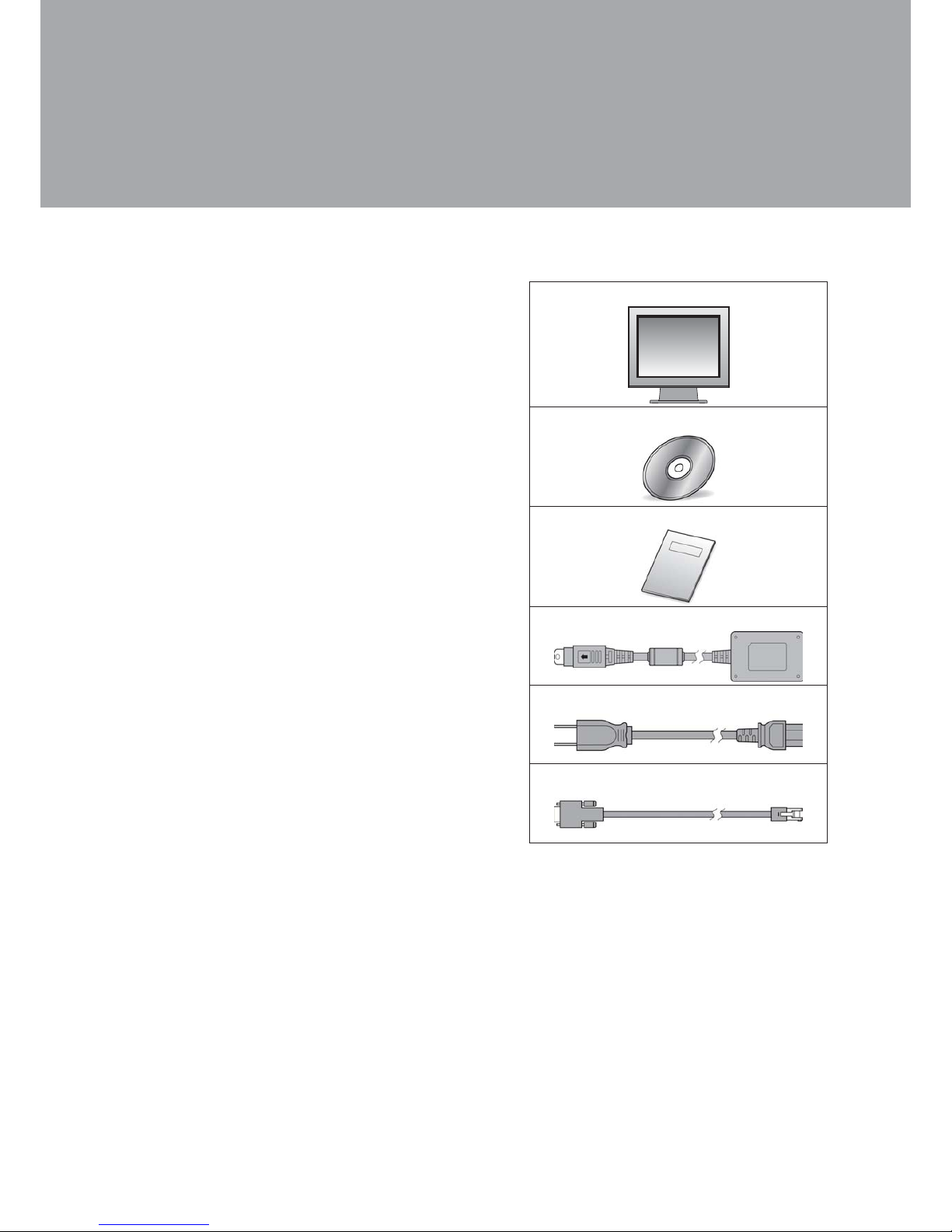
Packing List1.
Standard Accessories
1-1.
a.
b.
c.
d.
e.
f.
System (with stand)a.
Driver bankb.
User guidec.
Power adapterd.
Power corde.
RJ45-DB9 cable (x2)f.
Page 9
2
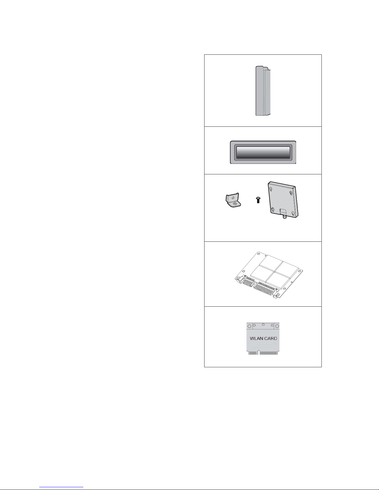
Optional Accessories
1-2.
a.
b.
c.
d.
e.
Metal MSRa.
Metal VFDb.
Wall-mount Kitc.
SSD moduled.
WLAN Card (with internal antenna)e.
a
b
c
Page 10
3
2
System View2.
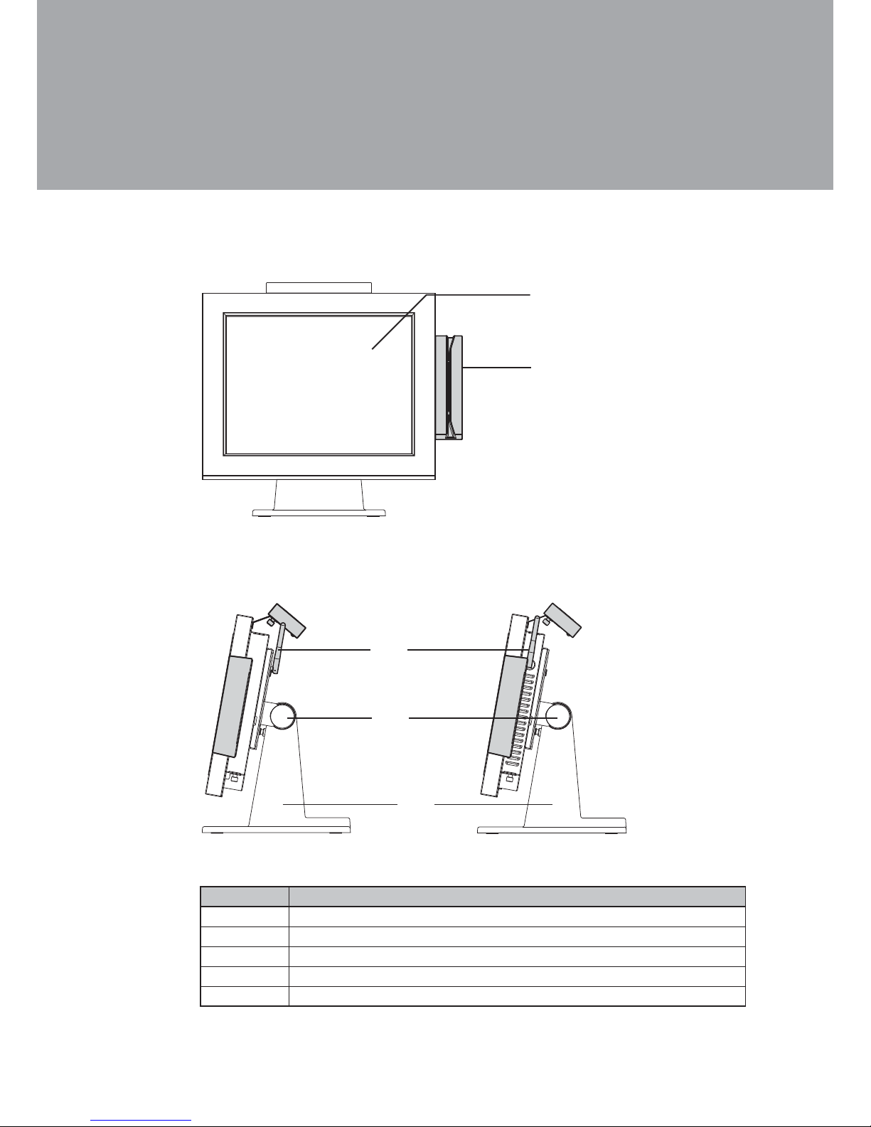
Front View
2-1.
Side View
2-2.
3
4
5
Fanless System Fan System
Item No. Description
1 Touch Screen
2 MSR Module (Optional)
3 External Antenna (Optional)
4 Hinge Cover for stand installation
5 Stand
1
Page 11
4
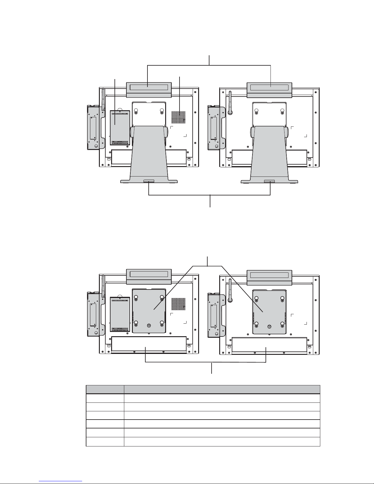
Rear View with stand
2-3.
6
7
8
9
Fan System
Fanless System
Rear View without wall mount bracket
2-4.
11
10
Fan System
Fanless System
Item No. Description
6 VFD (Optional)
7 HDD Door for fan system
8 Ventilation for fan system
9 Cable management outlet
10 VESA hinge bracket
11 I/O ports cover
Page 12
5
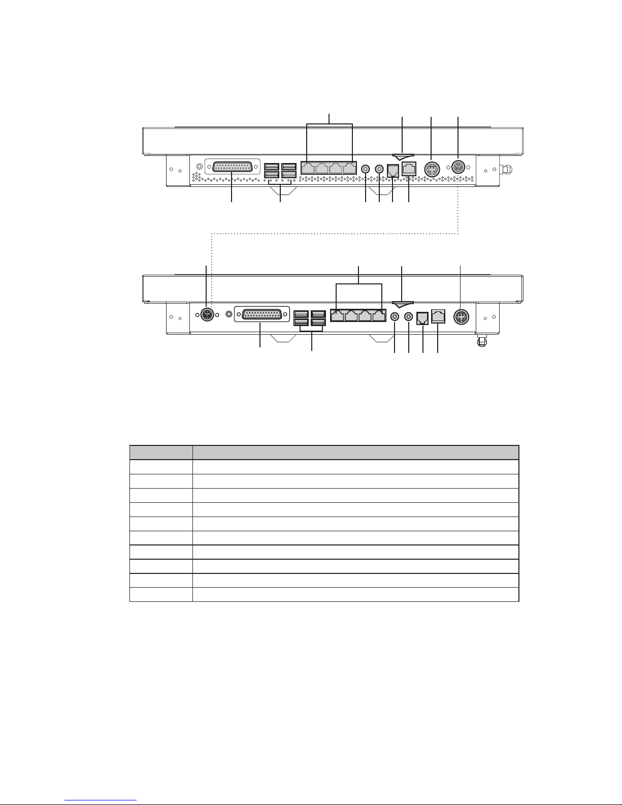
I/O Ports View
2-5.
a b
c
de f g
hij
Fanless System
a b
c
def g
hi
j
Fan System
Item No. Description
a Parallel
b USB x 4
c COM 1, 2, 3, 4 (from right to left)
d Line-out
e MIC-in
f Cash Drawer (12V or 19V, can support 24V)
g LAN
h Power Switch
i DC-In
j PS/2
Note: The I/O ports location may slightly different depending to the fan or
fanless system installed.
Page 13
6
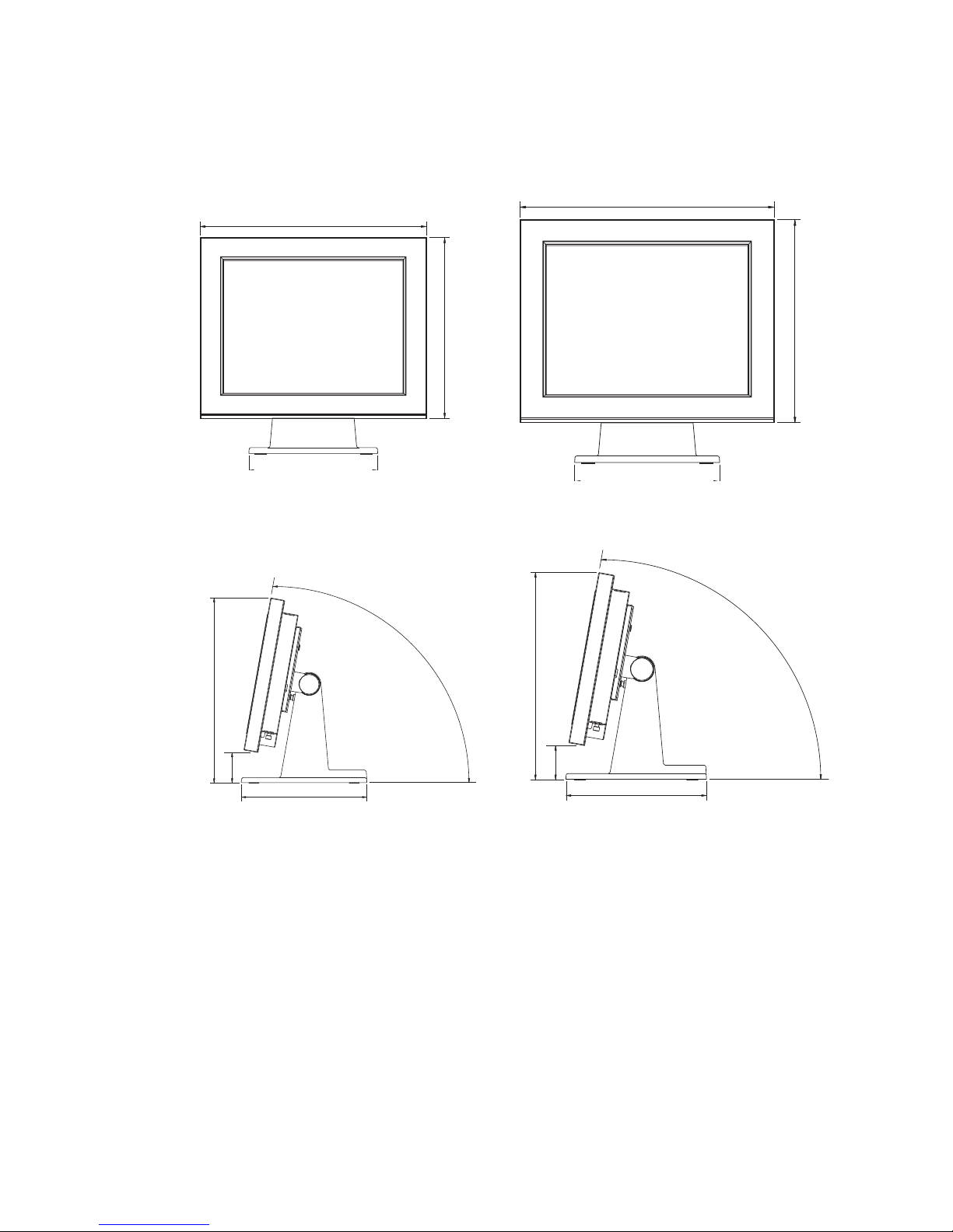
System Dimension
2-6.
386 mm
308 mm
220 mm
370 mm
62 mm
250 mm
80 °
411 mm
390 mm
220 mm
407 mm
63 mm
250 mm
80 °
15" System 17" System
Page 14
7
System Assembly3.
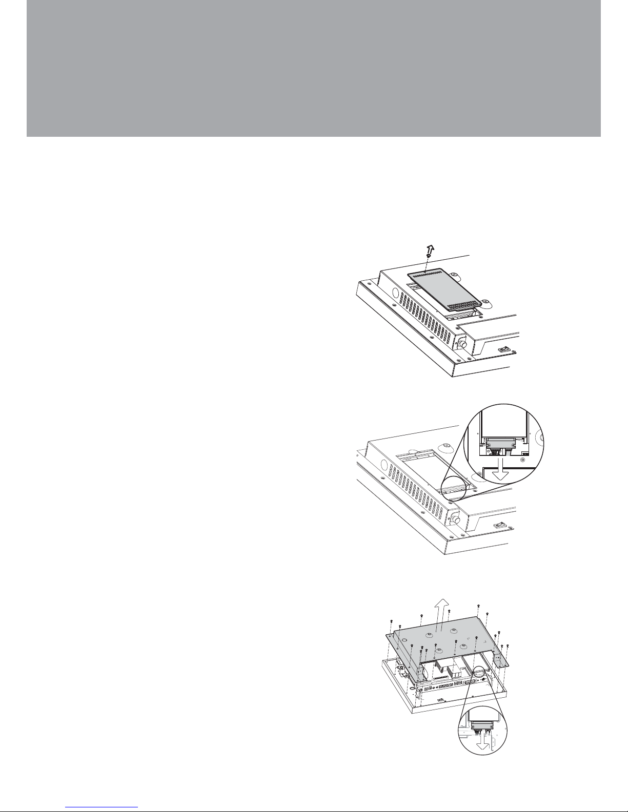
Turn to the rear side of the system.1.
Unscrew the screw (x1) securing 2.
the HDD door and the rear cover
of the system.
Disconnect the SATA cable from 3.
the drive.
HDD replacement for fan system
3-1.
HDD replacement for fanless system
3-2.
To remove and replace the HDD, please follow below steps. The procedures may
be different depending on the fan or fanless system being installed.
Turn to the rear side of the system 1.
and unfasten the screws (x17) to
separate the rear cover from the
system. The HDD is installed on the
motherboard. If your system install
with a stand or a wall mount bracket,
please remove them beforehand.
(Refer to Chapter 4-3 or 4-4)
Disconnect the HDD cable and 2.
replace the HDD.
Page 15
8
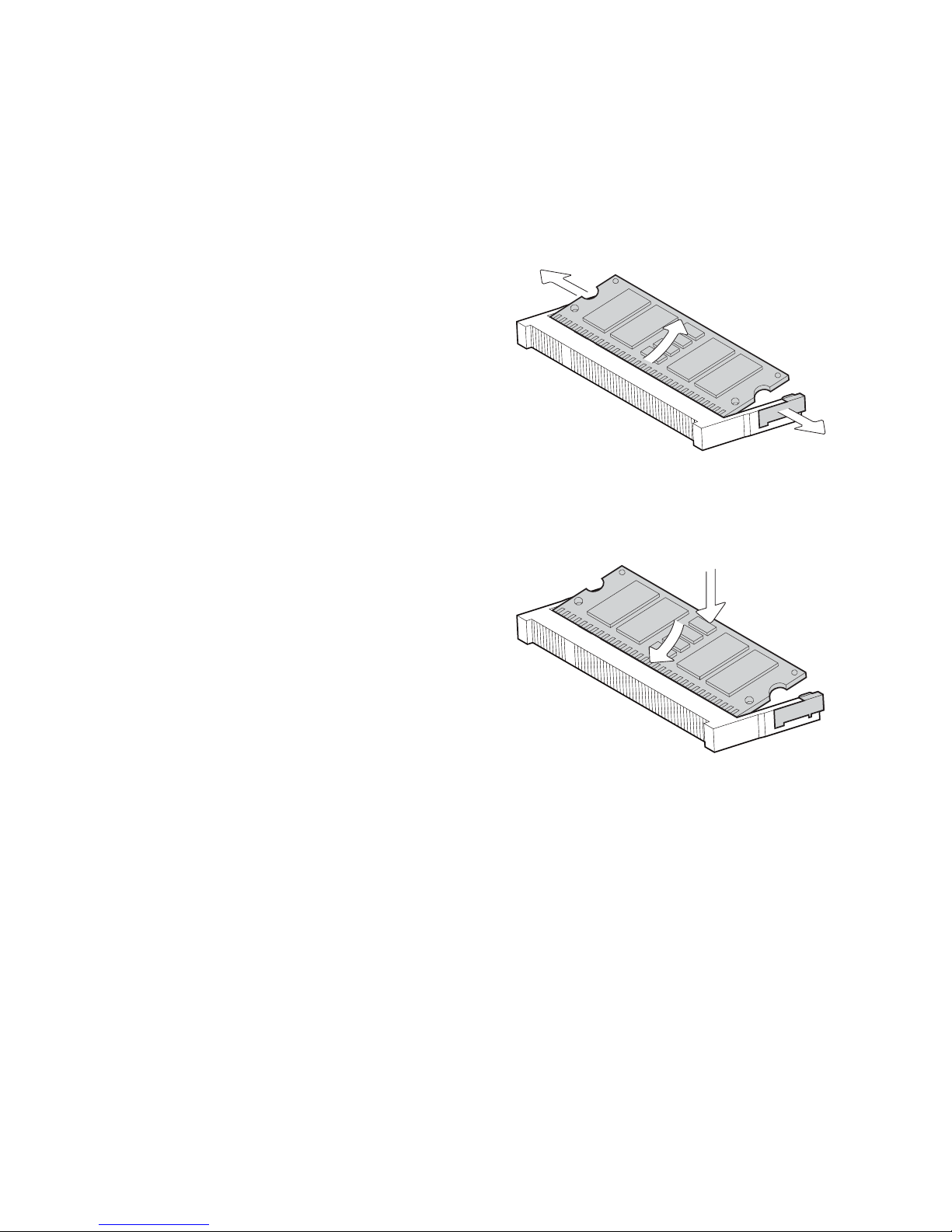
Removing a RAM module
Please Open the rear cover by 1.
unfasten the screws (x17) to
access the motherboard.
Use both fingers to pull the ejector 2.
clips out of the sides of the module.
Slide out to take out the memory 3.
module from the memory slot.
Installing a RAM module
Slide the memory module into the 4.
memory slot and press down until
it fix with the ejector clips.
RAM Replacement
3-3.
Please open the rear cover (see Chapter 3-1 or 3-2) first then remove and
replace the RAM module. You can refer to the motherboard layout to find the
memory compartment. (See chapter 6 for different motherboard)
Page 16
9
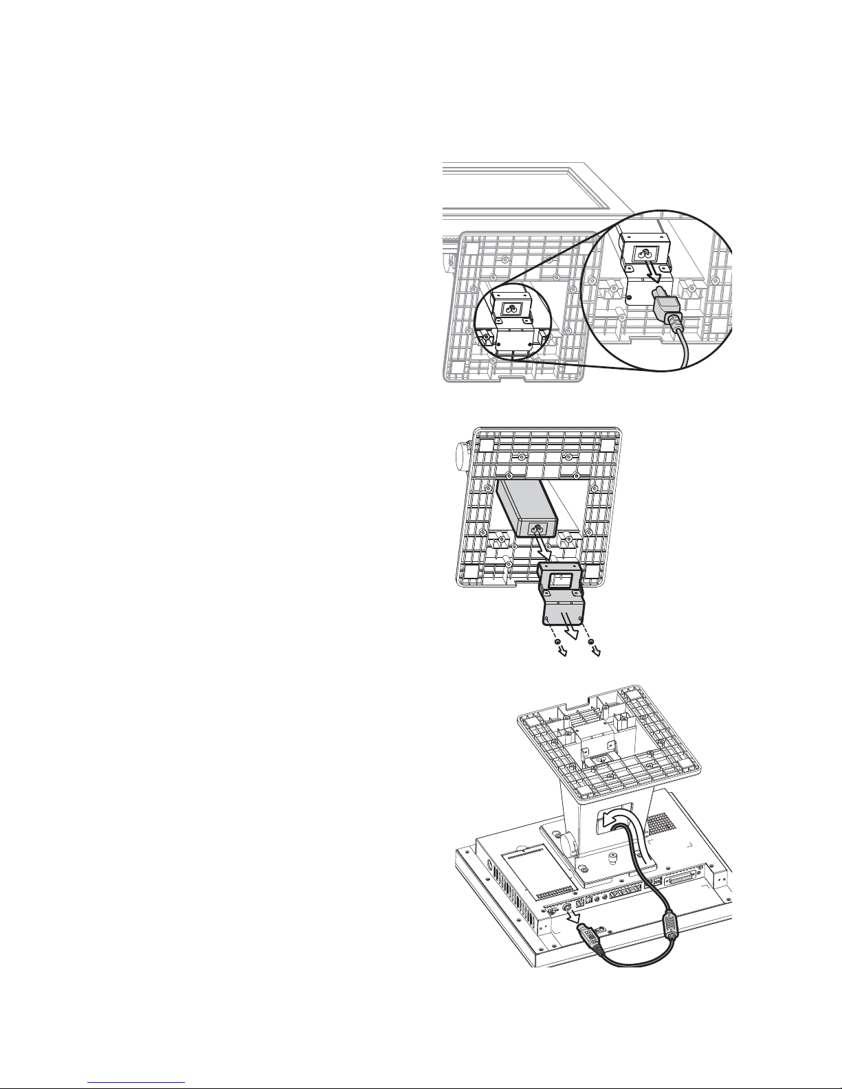
Power Adapter Replacement
3-4.
Disconnect the power cable from 1.
the adapter pre-installed in the
power bracket attached in the
stand.
Unscrew the screws (x2) and 2.
separate the power bracket from
the stand.
Disconnect the other end of the 3.
power adapter from the connector
on the I/O panel.
Draw out the power adapter gently 4.
through the cable management
hole on the stand.
Replace the power adapter by 5.
reversing the procedure of above
steps.
Page 17
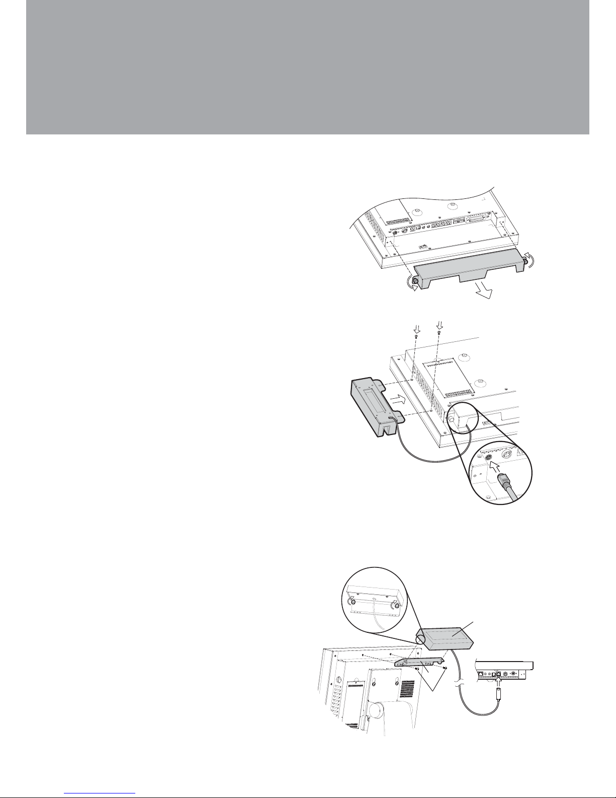
10
Peripheral Installation4.
MSR Installation
4-1.
Unfasten the thumb screws (x2) to 1.
remove the I/O cover.
Connect the MSR module into the 2.
system and fasten the screws (x2).
Connect the PS/2 Connector into 3.
the PS/2 port on the I/O panel.
Note: the PS/2 port locates in different
places on the I/O panel according
to the fan or fanless system being
installed.
Connect the VFD metal bracket 1.
into the system with screws (x2)
Fasten the VFD module to the 2.
metal bracket by fastening the
thumb screws (x2).
Connect the VFD cable to the 3.
RJ45 connector on the I/O panel.
VFD Installation
4-2.
a
b
c
VFD Accessories
VFD modulea.
VFD metal bracket b.
(with RJ45 cable)
Screws (x2)c.
Page 18
11
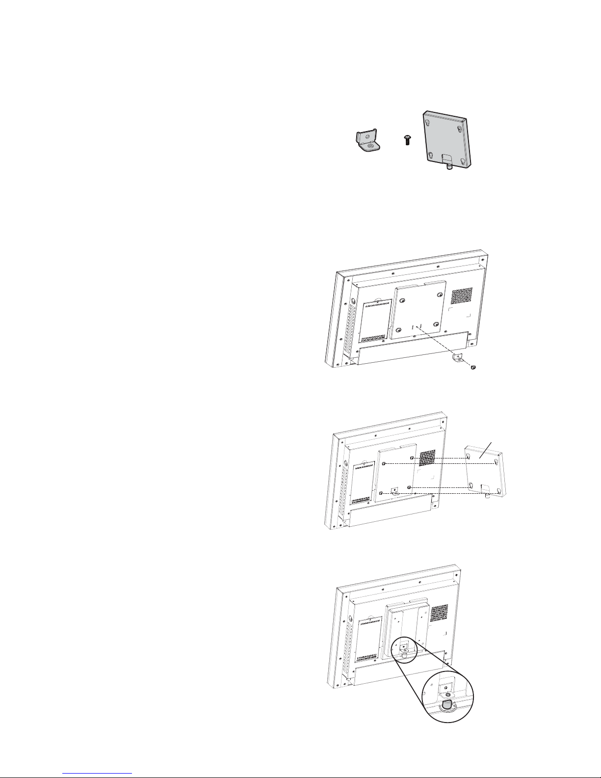
Wall Mount Kit Assembly
4-3.
Fix the metal bracket (a) to the 1.
VESA bracket and the display with
the screw (b) (x1).
Align the tear drop holes of the 2.
wall mount bracket (c) into the 4
VESA bracket screws.
Fasten the thumb screw of the 3.
wall mount bracket (a) to fix the
wall mount bracket (c) to the VESA
bracket.
Accessories items
a. Metal bracket with thumb screw
b. Screw x 1
c. Wall mount bracket
c
a
b
c
Page 19
12
a
f
b
d
e
c
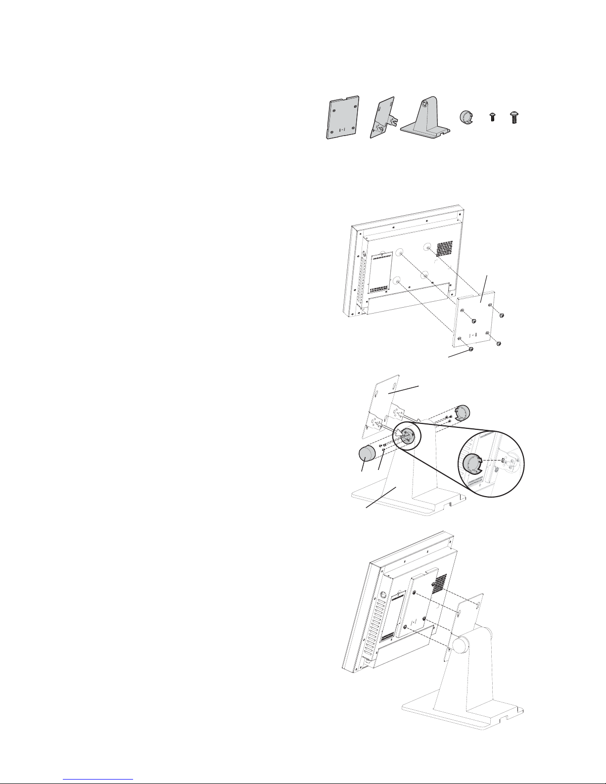
Desktop Stand Assembly
4-4.
VESA bracket assembly
Align the standard VESA mounting 1.
holes of the VESA bracket (a) and
the display and fix them with the
screws provided (f) (x4).
Stand bracket assembly
Align the guide slot of the stand 2.
bracket (b) into the hinge shaft of
the stand (c).
Fasten the screws (e) (x3) on each 3.
sides to fix the stand bracket (b) to
the stand (c).
Align the hinge cover (d) (x2) into 4.
the right position of the stand
bracket (b) and fix it until you hear
a click sound.
Align the screws (f) (x4) on the 5.
VESA bracket (a) pre-installed on
the display to the four tear drop
holes of the stand bracket (b) preinstalled with the stand.
Accessories items
a. VESA bracket
b. Stand bracket
c. Stand
d. Hinge cover x2
e. Screws for both sides of stand x6
f. Screws for VESA bracket x 4
abc def
Page 20
13
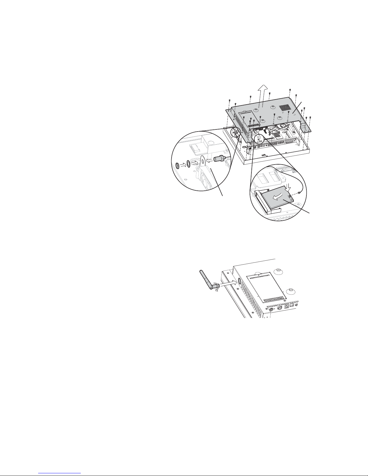
Wireless LAN Installation
4-5.
Disconnect the HDD cable from the 1.
system first (see Chapter 3-1).
Unscrew the screws (x17) to 2.
remove the rear cover (a).
Assemble the antenna cable (b) 3.
by fasten the nut, washer
and the coaxial cable as
picture instructs.
Insert the WLAN card 4.
(c) to the WLAN socket
on the motherboard and
press it downward until the
ejector clips lock it in place.
Connect the antenna cable to the 5.
“main connector” on the WLAN
card.
Cover the rear cover by reversing 6.
the step 2.
The pre-drilled hole for the external 7.
antenna installation is built in
the side of the rear cover on a
fan system. Rotate the external
antenna clockwise and fasten
to the connector of the internal
antenna cable.
On a Fan System4-5-1.
c
b
a
Page 21
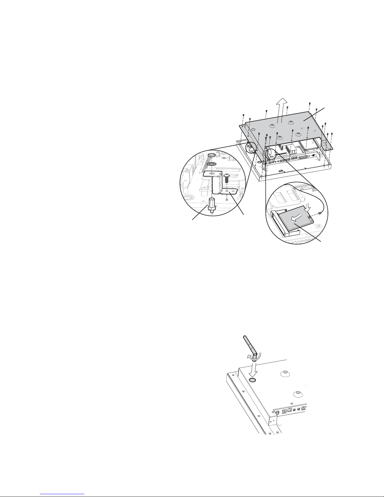
14
c
d
b
a
Open the rear cover by removing 1.
the screws (x17)
Fix the antenna mounting bracket 2.
(b) with the screw (x1) onto the
LCD chassis under the rear cover.
Assemble the antenna cable by 3.
inserting the coaxial cable to
the pre-drilled hole of the
bracket (b) and fastening
with the nut and the
washer with the mounting
bracket.
Insert the WLAN card (c) 4.
to the WLAN socket on the
motherboard and press it
downward until the ejector
clips lock it in place.
Connect the antenna cable to the 5.
“main connector” on the wireless
LAN card.
On a Fanless System4-5-2.
For installing the external antenna and the wireless LAN card for fanless System,
please see below pictures and instructions.
Cover the rear cover again by 6.
reverse the step 2.
The drilled hole is built-in the rear 7.
side of the rear cover on a fanless
system. Rotate the external
antenna clockwise and fasten to
the connector of internal antenna
cable.
Page 22
15
SSD Card Replacement
4-6.
On a Fan System4-6-1.
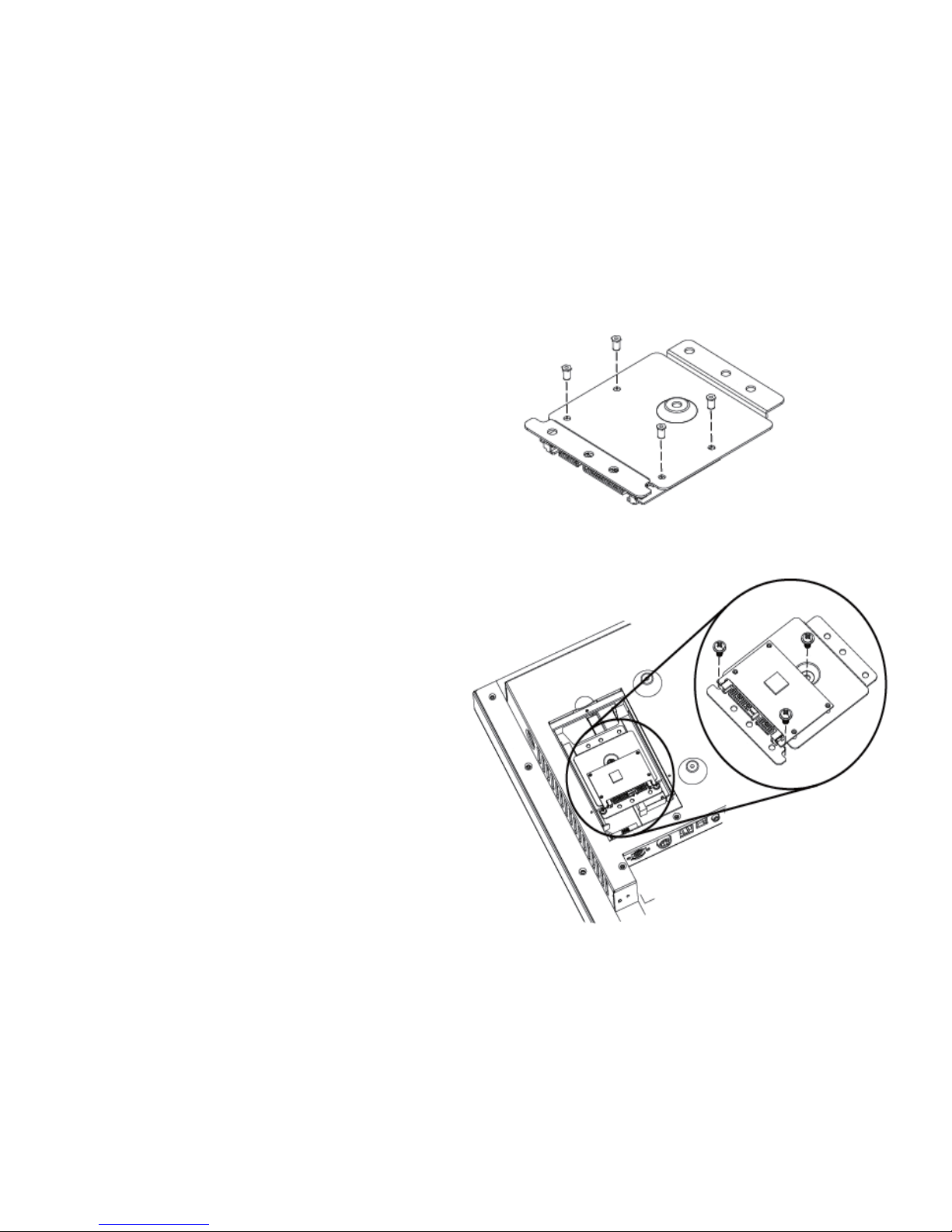
If your system equipped with SSD Card instead of hard drive disk as storage
device, please follow below steps to replace the SSD card.
2. Turn to the rear side and open
the HDD door on a fan system
(see Chapter 3-1).
3. Fasten the screw (x3) as
shown to fix the SSD module.
1. Fasten the screw(x4) on the
rear side of the SSD holder
bracket to fix the SSD card.
Page 23
16
On a Fanless System4-6-2.
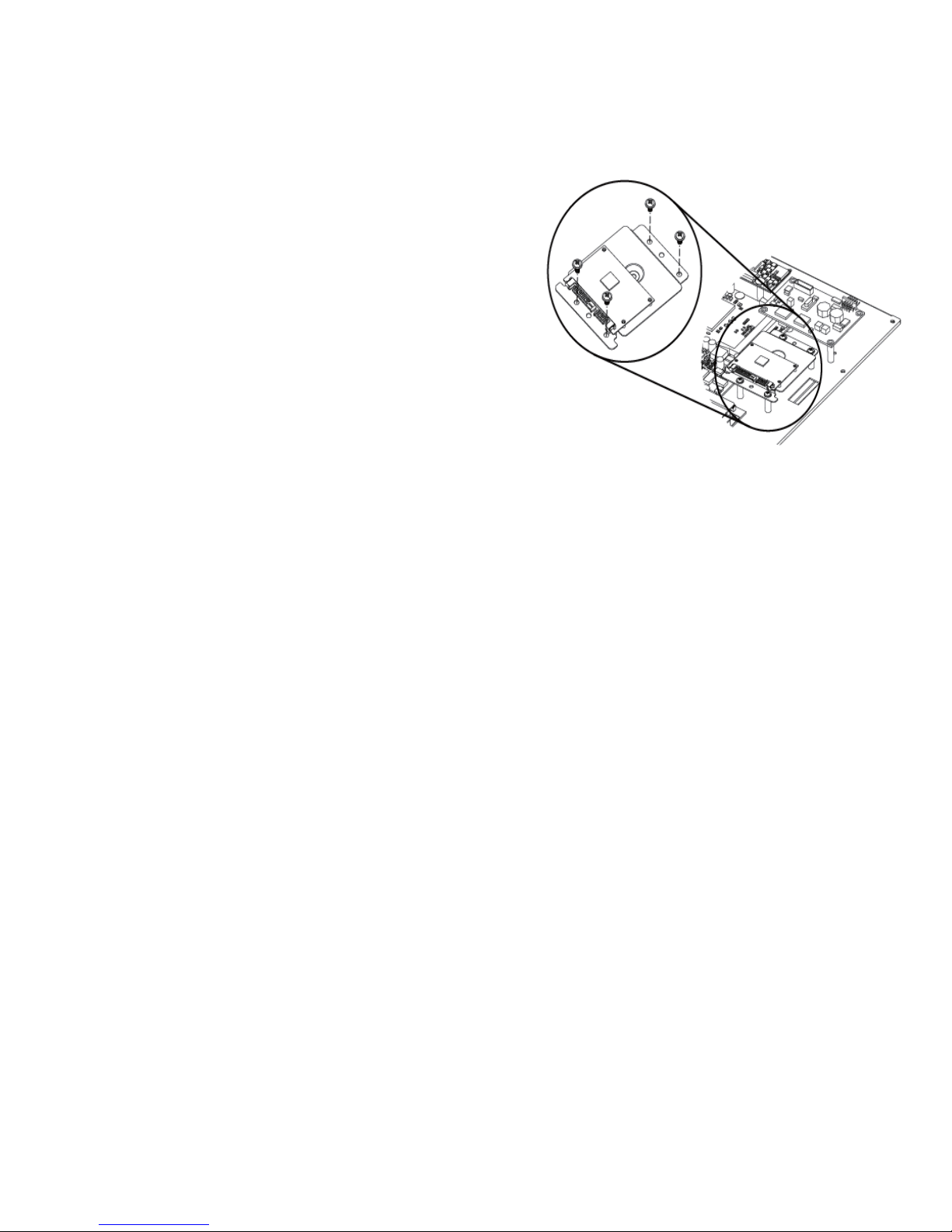
1. Follow 4-6-1 step 1 to assemble SSD
module.
2. Turn to the rear side and open the
rear cover on a fanless system (see
Chapter 3-2).
3. Fasten the screw (x4) as shown to fix
the SSD module.
Page 24
17
Cash Drawer Installation
4-7.
For B78 motherboard4-7-1.
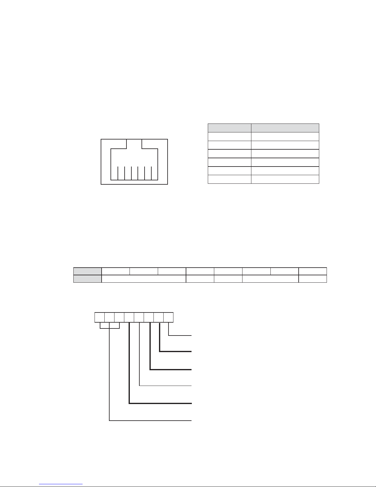
You can install a cash drawer through the cash drawer port. Please verify the pin
assignment before installation.
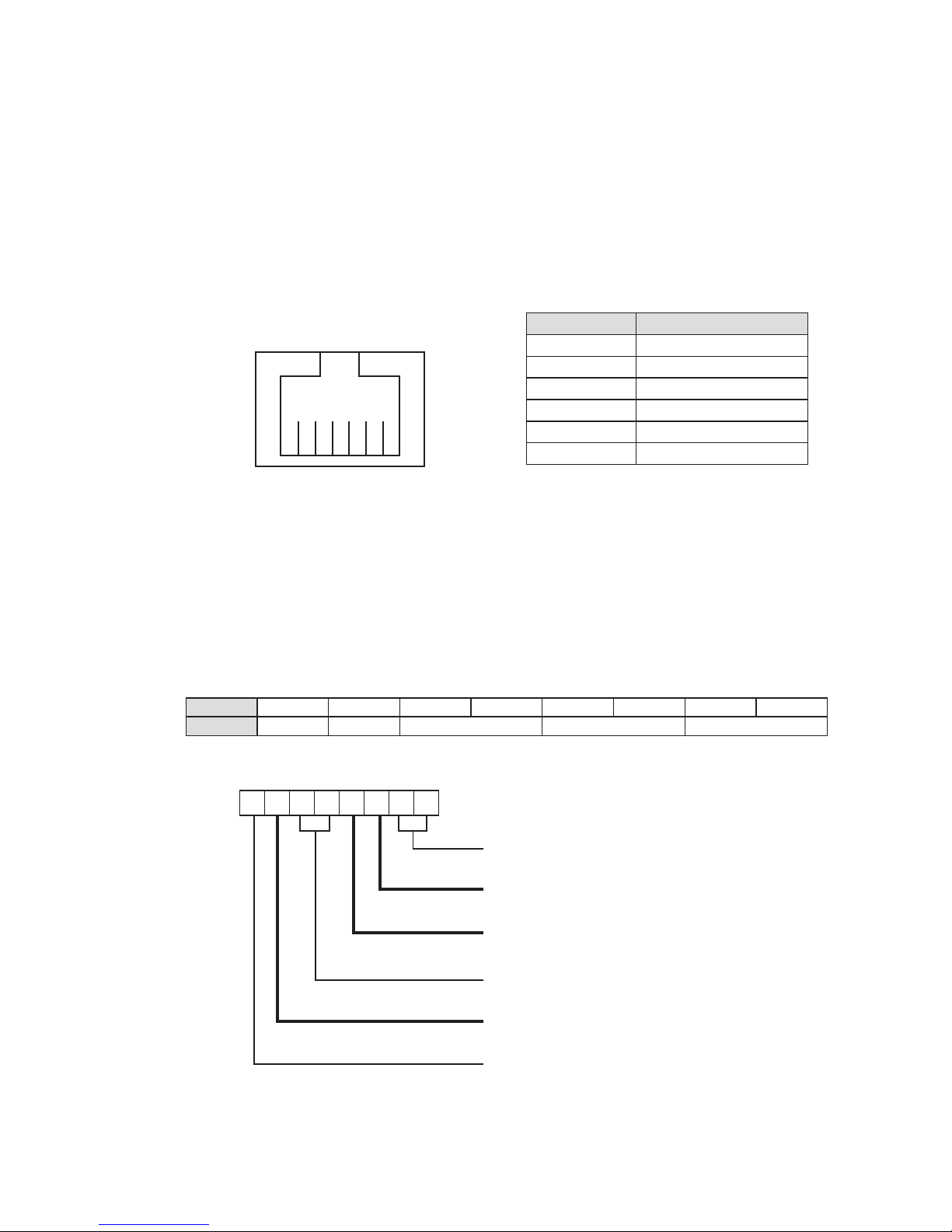
Cash Drawer Pin Assignment
Pin Signal
1 GND
2 DOUT bit0
3 DIN bit0
4 12V / 19V
5 DOUT bit1
6 GND
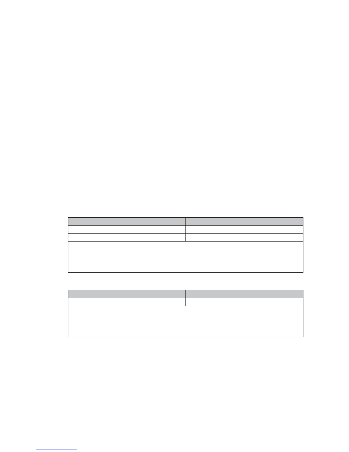
Cash Drawer Controller Register
The Cash Drawer Controller use one I/O addresses to control the Cash Drawer.
Register Location: 4B8h
Attribute: Read / Write
Size: 8bit
BIT BIT7 BIT6 BIT5 BIT4 BIT3 BIT2 BIT1 BIT0
Attribute Reserved Read Reserved Write Reserved
76543210
X
X X X X
Reserved
Cash Drawer “DOUT bit1” pin output control
Cash Drawer “DOUT bit0” pin output control
Reserved
Cash Drawer “DIN bit0” pin input status
Reserved
1
6
Page 25
18
Bit 7: Reserved.
Bit 6: Reserved.
Bit 5: Reserved.
Bit 4: Cash Drawer “DIN bit0” pin input status.
= 1: the Cash Drawer closed or no Cash Drawer.
= 0: the Cash Drawer opened.
Bit 3: Reserved.
Bit 2: Cash Drawer “DOUT bit0” pin output control.
= 1: Opening the Cash Drawer
= 0: Allow closing the Cash Drawer
Bit 1: Cash Drawer “DOUT bit1” pin output control.
= 1: Opening the Cash Drawer
= 0: Allow closing the Cash Drawer
Bit 0: Reserved
Note: Please follow the Cash Drawer control signal design to control the Cash
Drawer
Cash Drawer Control Command Example
Use Debug.EXE program under DOS or Windows98
Command Cash Drawer
O 4B8 04 Opening
O 4B8 00 Allow to closing
Set the I/O address 4B8h bit2 =1 for opening the Cash Drawer by “DOUT bit0” ►
pin control.
Set the I/O address 4B8h bit2 = 0 to allow closing Cash Drawer. ►
Command Cash Drawer
I 4B8 Check status
The I/O address 4B8h bit4 =1 means the Cash Drawer is closed or no Cash ►
Drawer.
The I/O address 4B8h bit4 =0 means the Cash Drawer is open. ►
Page 26
19
For B68/B98/C48 motherboard4-7-2.
You can install a cash drawer through the cash drawer port. Please verify the pin
assignment before installation.
Below cash drawer installation is applicable for B68, B98 and C48 motherboard.
Cash Drawer Pin Assignment
Pin Signal
1 GND
2 DOUT bit0
3 DIN bit0
4 12V / 19V
5 DOUT bit1
6 GND
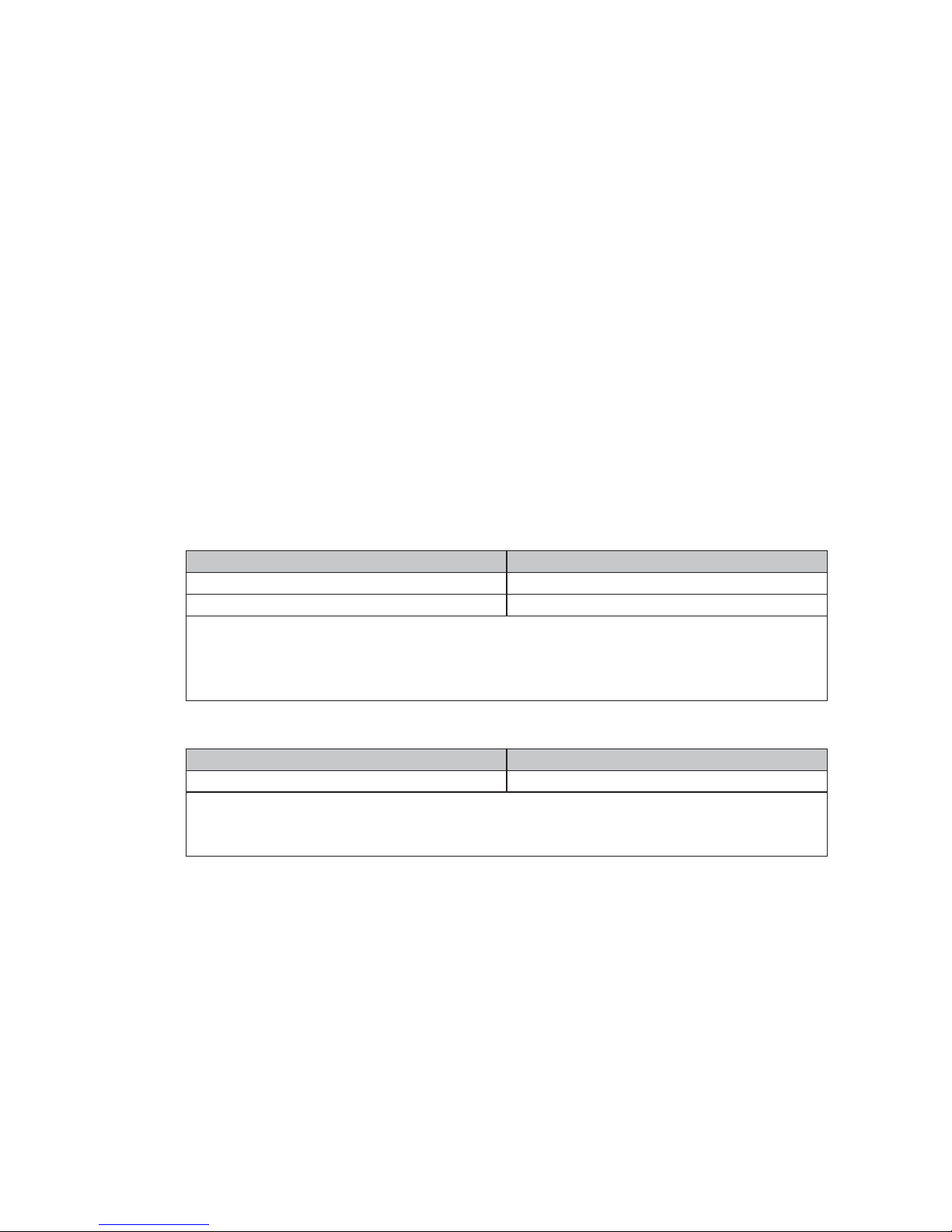
Cash Drawer Controller Register
The Cash Drawer Controller use one I/O addresses to control the Cash Drawer.
The Cash Drawer Control Register and the Cash Drawer Status Register.
Register Location: 48Ch
Attribute: Read / Write
Size: 8bit
BIT BIT7 BIT6 BIT5 BIT4 BIT3 BIT2 BIT1 BIT0
Attribute Reserved Read Reserved Write Reserved
76543210
X
X X X X
Reserved
Cash Drawer “DOUT bit0” pin output control
Cash Drawer “DOUT bit1” pin output control
Reserved
Cash Drawer “DIN bit0” pin input status
Reserved
1
6
Page 27
20
Bit 7: Reserved
Bit 6: Cash Drawer “DIN bit0” pin input status.
= 1: the Cash Drawer closed or no Cash Drawer
= 0: the Cash Drawer opened
Bit 5: Reserved
Bit 4: Reserved
Bit 3: Cash Drawer “DOUT bit1” pin output control.
= 1: Opening the Cash Drawer
= 0: Allow close the Cash Drawer
Bit 2: Cash Drawer “DOUT bit0” pin output control.
= 1: Opening the Cash Drawer
= 0: Allow close the Cash Drawer
Bit 1: Reserved
Bit 0: Reserved
Note: Please follow the Cash Drawer control signal design to control the Cash
Drawer.
Cash Drawer Control Command Example
Use Debug.EXE program under DOS or Windows98
Command Cash Drawer
O 48C 04 Opening
O 48C 00 Allow to close
Set the I/O address 48Ch bit2 =1 for opening Cash Drawer by “DOUT bit0” pin ►
control.
Set the I/O address 48Ch bit2 = 0 for allow close Cash Drawer. ►
Command Cash Drawer
I 48C Check status
The I/O address 48Ch bit6 =1 mean the Cash Drawer is opened or not exist. ►
The I/O address 48Ch bit6 =0 mean the Cash Drawer is closed. ►
Page 28
21
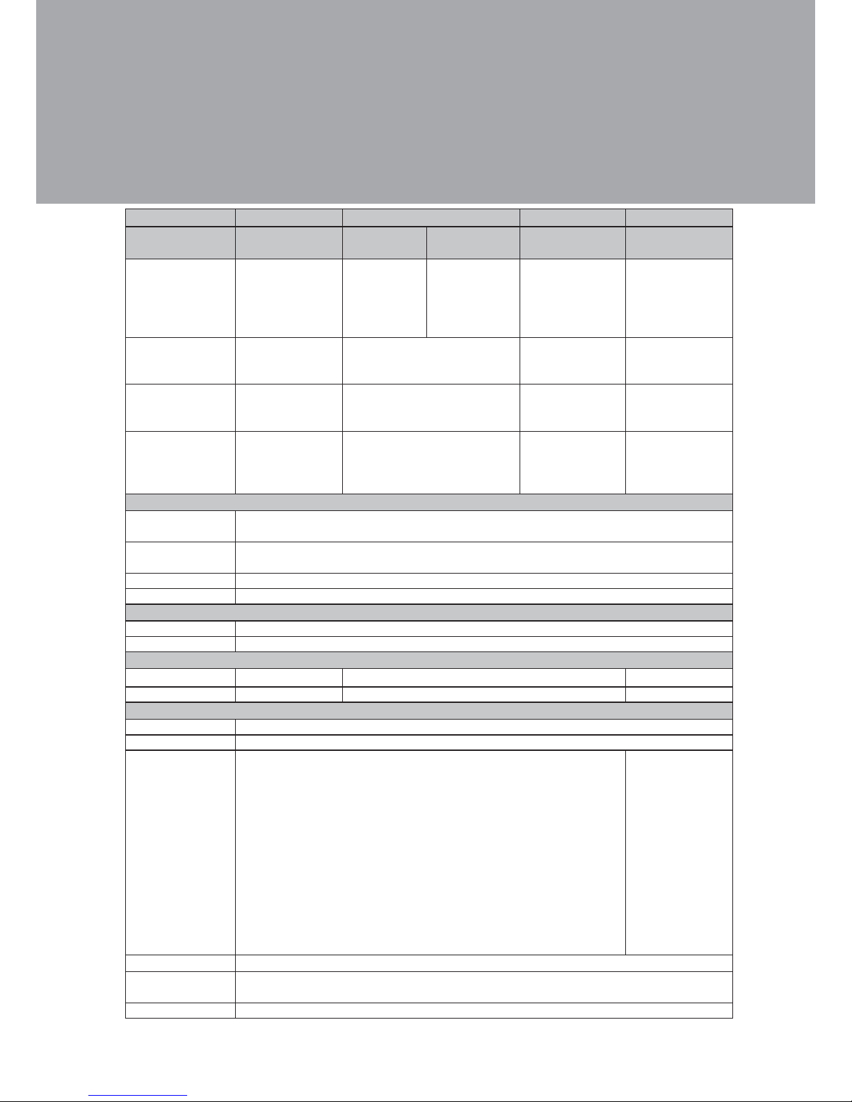
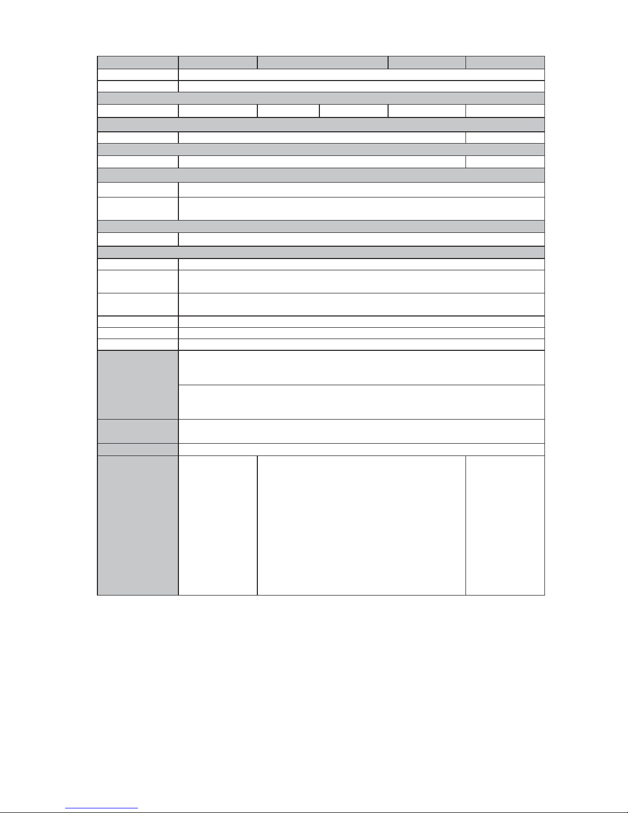
Motherboard B68 B78 B98 C48
Fan/Fanless Fanless Fanless
Fan
(performance)
Fan
(Performance)
Fanless
CPU Support
Intel Atom N270
processors 1.6G
(BGA)
Intel Celeron
M ULV 1.0GHz
(BGA)
Intel Celeron
M 1.5GHz
/ Pentium
M 1.8GHz
(Socket)
Intel Celeron
M 1.86GHz /
Core duo 2.0GHz /
Core 2 duo
1.66GHz (socket)
Intel Pineview D525
dual core 1.8G L2
1M, FSB800MHz
Chipset
Intel 945GSE
+ ICH7M FSB
533MHz
Intel 852GM + ICH4 FSB
400MHz
Intel 945GME
+ ICH7M FSB
400/533/667MHz
CPU with Graphic
built-in + ICH 8M
System Memory
2 x DDR2 SO-
DIMM Slot support
up to 2GB
2 x DDR SO-DIMM Slot support
up to 2GB
2 x DDR2 SO-
DIMM Slot support
up to 4GB
2 x DDR3 DIMM
up to 4GB, FSB
800Mhz
Graphic Memory
Share system
memory up to
224MB
Shared system memory up to
64MB
Shared system
memory up to
224MB
Intel GMA 3150,
share system
memory up to
256MB
LCD Touch Panel
Brightness 15" TFT LCD: 250nits
17" TFT LCD: 250~400nits
Maximal Resolution 15" TFT LCD: 1024 x 768
17" TFT LCD: 1280 x 1024
Touch Screen Type Resistive / SAW (optional)
Tilt Angle 0° ~ 80°
Storage
HDD one slim HDD bay support SATA HDD
Flash Memory by optional SSD card (without HDD)
Expansion
Mini-PCI Slot N/A 1 N/A
Mini-PCI-E Slot 1 N/A 1
External I/O Ports
USB 4 ports (V2.0)
PS2 1
Serial / COM
4 x COM ports RJ-45 connectors
( COM1 & COM2 standard RS-232; COM3 & COM4 pin9 with 5V /12V
power by jumper )
4 x RJ 45 COM
(COM1/COM2
standard RS232 without
power, COM3 /
COM4 powered
COM with power
enable /disable by
BIOS setting and
+5V/+12V by MB
setting. COM3
default +5V/ COM4
default +12V )
Parallel 1
LAN
(10 /100 / 1000)
1 x RJ45
DC Jack 1
Specification5.
Page 29
22
Motherboard B68 B78 B98 C48
Cash Drawer Port 1 x RJ 11 (12V /19V)
Audio Jack 1 x Line-out, 1 x Mic-in
Audio
Built in Speaker N/A N/A 2x2W 2x2W N/A
Power
Power Adapter 19V, 90W
Control
Power Button
1
Peripheral
Metal MSR
3 Tracks MSR ( PS/2 )
Metal Customer
Display
Flush mount VFD display 2 x 20 characters (COM)
Communication
Wireless LAN
802.11 a/b/g wireless LAN card & antenna
Environment
EMC & Safety FCC, Class A, CE, LVD
Operating
Temperature
5
o
C ~ 35oC (41oF ~ 95oF)
Storage
Temperature
-20
o
C ~ 55oC (-4oF ~ 140oF)
Operating Humidity 20% ~ 80% RH non condensing
Storage Humidity 20% ~ 85% RH non condensing
Dust & Water Proof IP 55 (Front bezel)
Dimension
(W x D x H)
Stand at LCD 80 degree :
15" TFT LCD: 386 x 250 x 370 mm (15.2" x 9.8" x 14.6")
17" TFT LCD: 411 x 250 x 390 mm (16.2" x 9.8" x 15.4")
Wall mount :
15" TFT LCD: 386 x 60 x 308 mm (15.2" x 2.4" x 12.1")
17" TFT LCD: 411 x 60 x 345 mm (16.2" x 2.4" x 13.6")
Weight
(N.W./G.W.)
15" TFT LCD: 12kgs / 13kgs
17" TFT LCD: 13kgs / 14kgs
Mounting
100mm x100mm VESA Standard holes
OS Support
Windows XP
Professional,
Windows XP
Embedded,
Windows CE,
Windows 7 & Vista
, POSReady 2009,
Linux
Windows 2000 Professional Embedded, Windows
XP, XP Professional Embedded, XP Embedded,
Vista (Vista only for B98), POSReady 2009 , Linux
Windows XP
Professional,
Windows
Embedded
POSReady
2009, Windows
XP Embedded,
Windows XP
Professional
for Embedded,
WinCE, Windows
7, Vista, Linux
* This specification is subject to change without prior notice.
Page 30
23
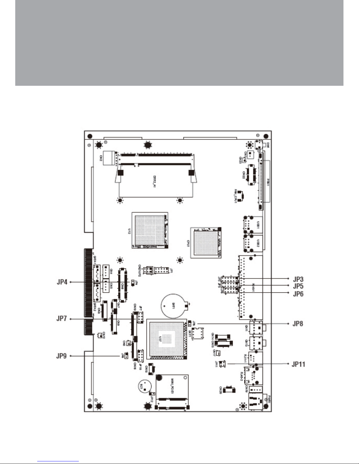
Version: B68 v1.0
For B68 Motherboard
6-1.
Jumper Setting6.
Motherboard Layout6-1-1.
Page 31

24
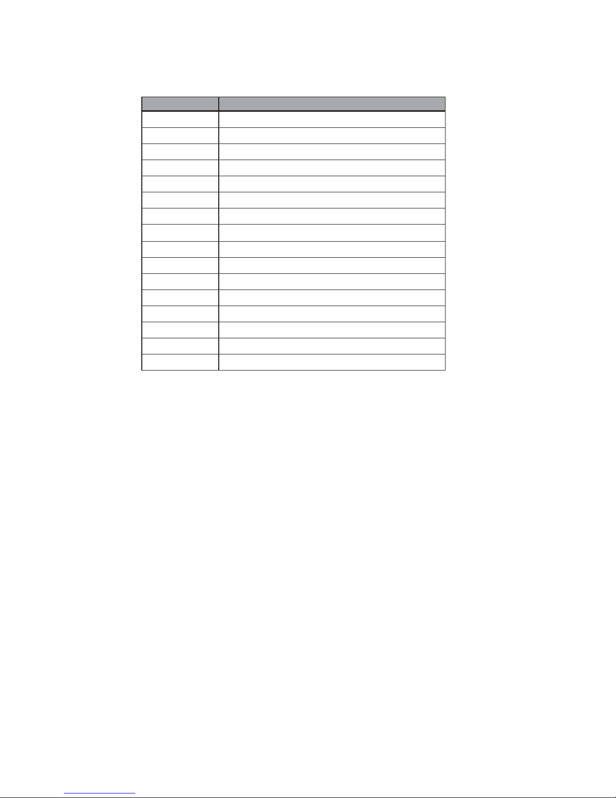
Connector Purpose
BAT1 CMOS Battery Base ( Use CR2023)
CN1 Power On Button
CN2 Touch Sensor
CN3 Power LED
CN4 SATA1 HDD Power Connector
CN5 SATA2 HDD Power Connector
CN6 LCD Interface Connector
CN7 IrDA Connector
CN8 For External Touch Connector
CN9 Inverter Connector
CN10 Card Reader Connector
CN11 Line Out
CN12 LED Power
CN13 MIC In
CN14 Speaker & MIC CONN
CN15 CD-IN CONN
CN16 FT Status Interface
CN17 LAN LED
CN18 USB5
CN19 DC-Jack
CN20 PS2 KEYBOARD
CN21 For Bedside Terminal
CN22 LPT Interface for Touch
CN23 For LPT Touch Reset
DDR2_A1 DDR2 SO-DIMM1
DDR2_A2 DDR2 SO-DIMM2
PRN1 Parallel Port
PWR1 +19V Power Adaptor
RJ11_1 Cash Drawer Connector
RJ45_1 COM1, COM2, COM3, COM4
RJ45_2 LAN
SATA1 SATA Connector
Connectors & Functions6-1-2.
Page 32
25
Connector Purpose
SATA2 SATA Connector
SKT1 SPI ROM
USB1 USB1, USB2
USB2 USB3, USB4
SW1 Power On Bottom
JP1 CRT Connector
JP2 CRT Power/I2C Connector
JP3 COM3/COM4 Power Setting
JP4 VGA Power Setting
JP5 COM2 Connector
JP6 COM2(RS232/422/485) Setting
JP7 LCD ID Setting
JP8 RTC Reset
JP9 Power Mode Setting
JP11 Cash Drawer Power Setting (+12V,+19V)
JP12 Hardware Reset
Page 33
26
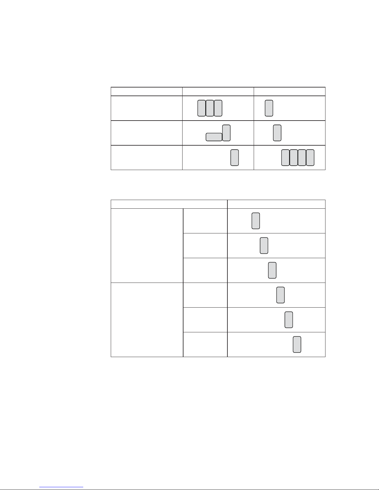
COM2 RS232/485/422 Setting
Function JP6 JP5
▲RS232
8 10
579
2
13
64
57911
2
13
6 8 10 124
RS485
810
579
2
1
3
64
11
12810
579
2
13
64
RS422
810
579
2
13
64 10
57911
2
13
68 124
COM3 & COM4 Power Setting
Function JP3
COM3 (Pin 10)
▲RI
57911
2
13
6 8 10 124
+5V
11
12810
579
2
13
64
+12V
11
12810
579
2
13
64
COM4 (Pin 10)
▲RI
11
12810
579
2
13
64
+5V
11
12810
579
2
13
64
+12V
11
12810
579
2
13
64
▲ = Manufacturer Default Setting
Jumper Setting6-1-3.
Page 34
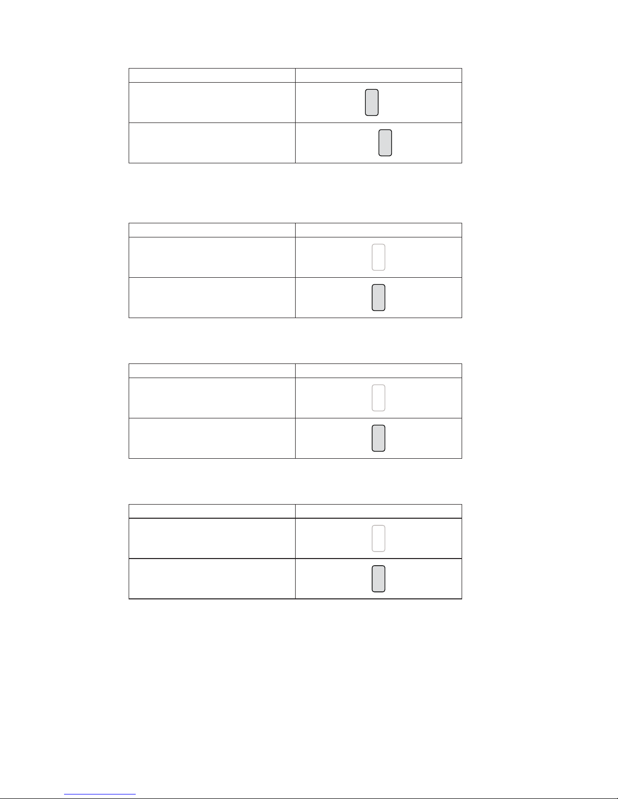
27
Cash Drawer Power Setting
Function JP11
▲+12V
2
13
4
+19V
2
13
4
Power Mode Setting
Function JP9
▲ATX Power
2
1
AT Power
2
1
RTC Reset
Function JP8
▲CMOS Normal
2
1
CMOS Reset
2
1
VGA Power Setting
Function JP4
▲No Power
2
1
+12V
2
1
▲ = Manufacturer Default Setting
Page 35
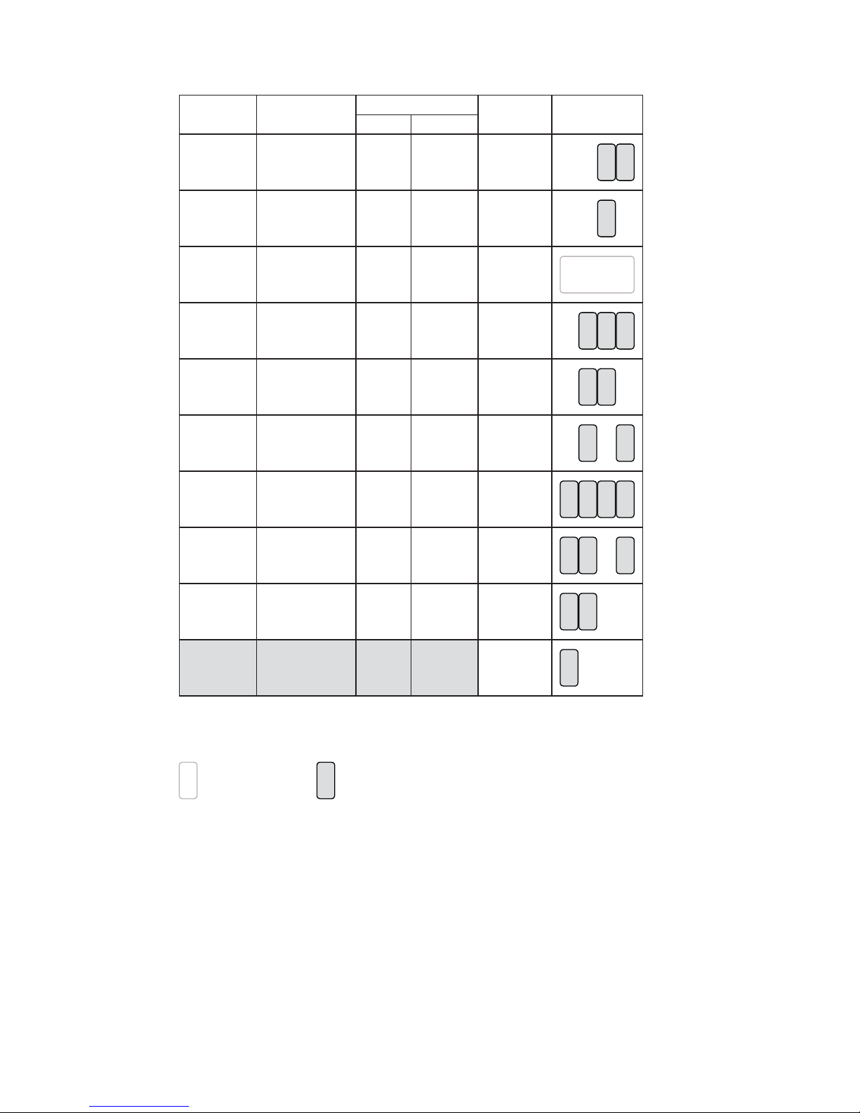
28
LCD ID Setting
Panel# Resolution
LVDS
Output
Interface
JP7
Bits Channel
1 1366 x 768 24 Single
LVDS
Panel
8
57
2
13
64
2 1440 x 900 24 Dual
LVDS
Panel
8
57
2
13
64
4 1920 x 1080 24 Dual
LVDS
Panel
8
57
2
13
64
5 1024 x 768 24 Single
LVDS
Panel
8
57
2
13
64
6 1280 x 1024 24 Dual
LVDS
Panel
8
57
2
13
64
7 800 x 600 24 Single
LVDS
Panel
8
57
2
13
64
9 1024 x 768 18 Single
LVDS
Panel
8
57
2
13
64
11 800 x 600 18 Single
LVDS
Panel
8
57
2
13
64
12 800 x 600 18 Single
LVDS
Panel
8
57
2
13
64
CRT
8
57
2
13
64
Remark:
Panel ID#12 is specialized for Sharp 12.1” LQ121S1LG41/LQ121S1LG42 panel
2
1
Jumper open
2
1
Jumper short
Page 36
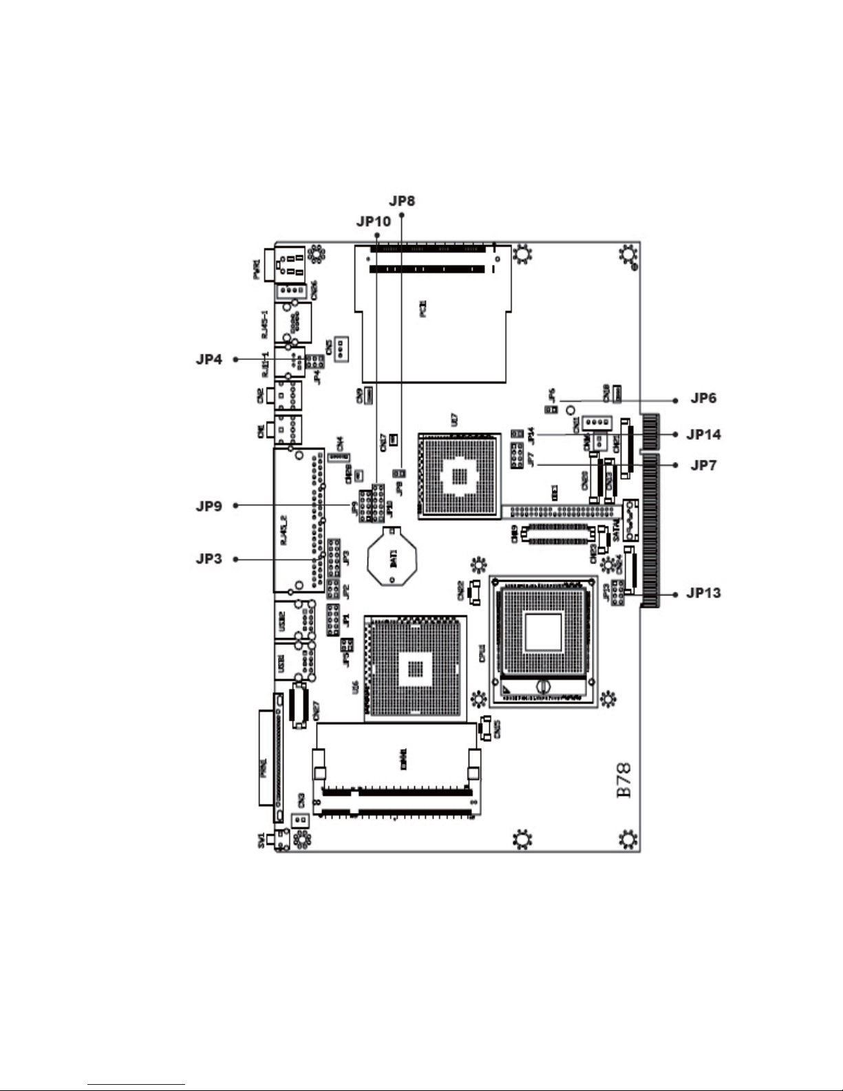
29
Version: B78 v2.2
For B78 Motherboard
6-2.
Motherboard Layout6-2-1.
Page 37
30
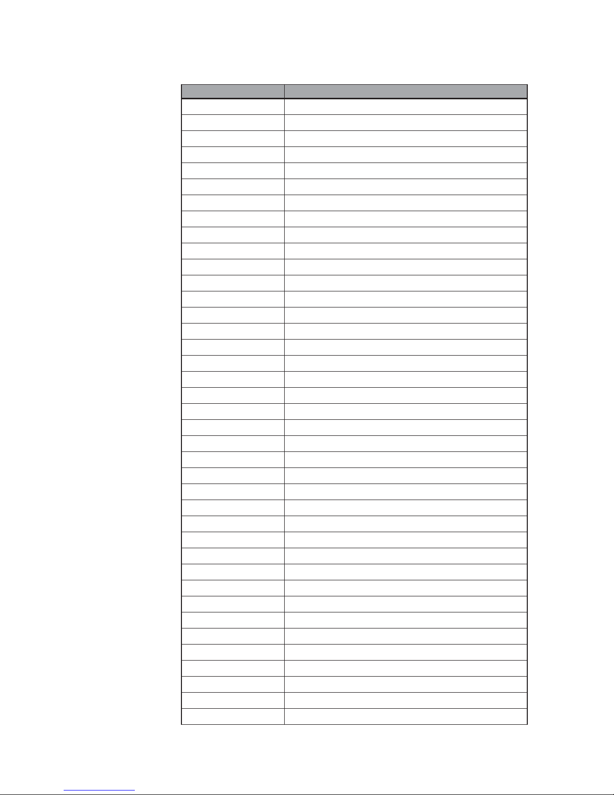
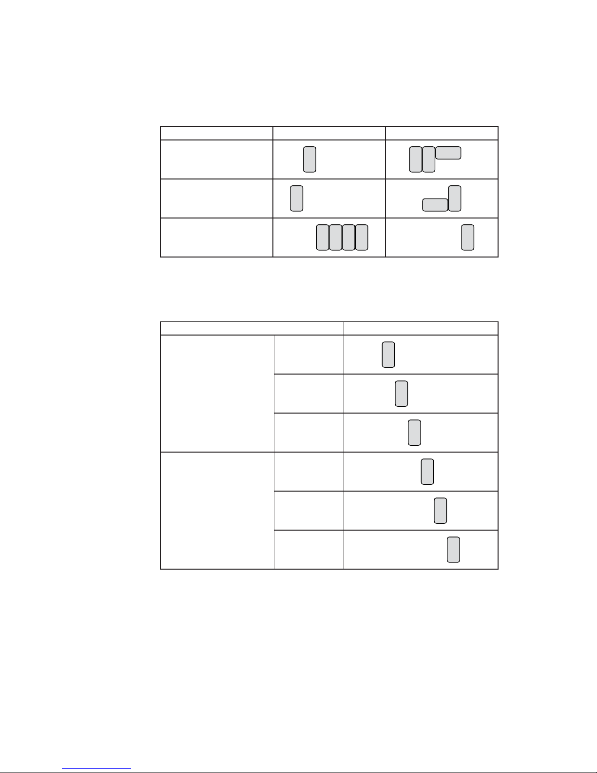
Connectors & Functions6-2-2.
Connector Purpose
BAT1 CMOS Battery Base ( Use CR2023)
CN1 Audio Line Out
CN2 Audio MIC In
CN3 Internal Power Switch
CN4 Speaker & MIC Connector
CN9 CD-IN Connector
CN11 Power Connector For 3.5" HDD
CN13 COM5 for Touch
CN15 CPU FAN Connector
CN16 Hardware Reset
CN18 USB2
CN19 LCD Interface Connector
CN20 Inverter Connector
CN21 Card Reader Connector
CN22 System FAN Connector
CN23 IrDA Connector
CN24 FT Status Interface
CN26 Internal Power In Connector
CN27 Internal LPT Connector
CN28 Internal PCI Reset Output Connector
IED1 Secondary IDE Connector (Pitch = 2.0mm)
PRN1 Parallel Port
PWR1 +19V Power Adaptor
RJ11_1 Cash Drawer Connector
RJ45_1 LAN (On Board)
RJ45_2 COM1, COM2, COM3, COM4
SATA1 SATA Connector
USB1 USB3, USB4
USB2 USB5, USB6
JP1 VGA Port
JP2 VGA Power
JP3 COM3/COM4 Power Setting
JP4 Cash Drawer Power Setting
JP6 Power Mode Setting
JP7 LCD ID Setting
JP8 CMOS Operation Mode
JP9/JP10 COM2 RS232/485/422 Setting
JP13 System Indicator Function
JP14 USB Path Setting
Page 38
31
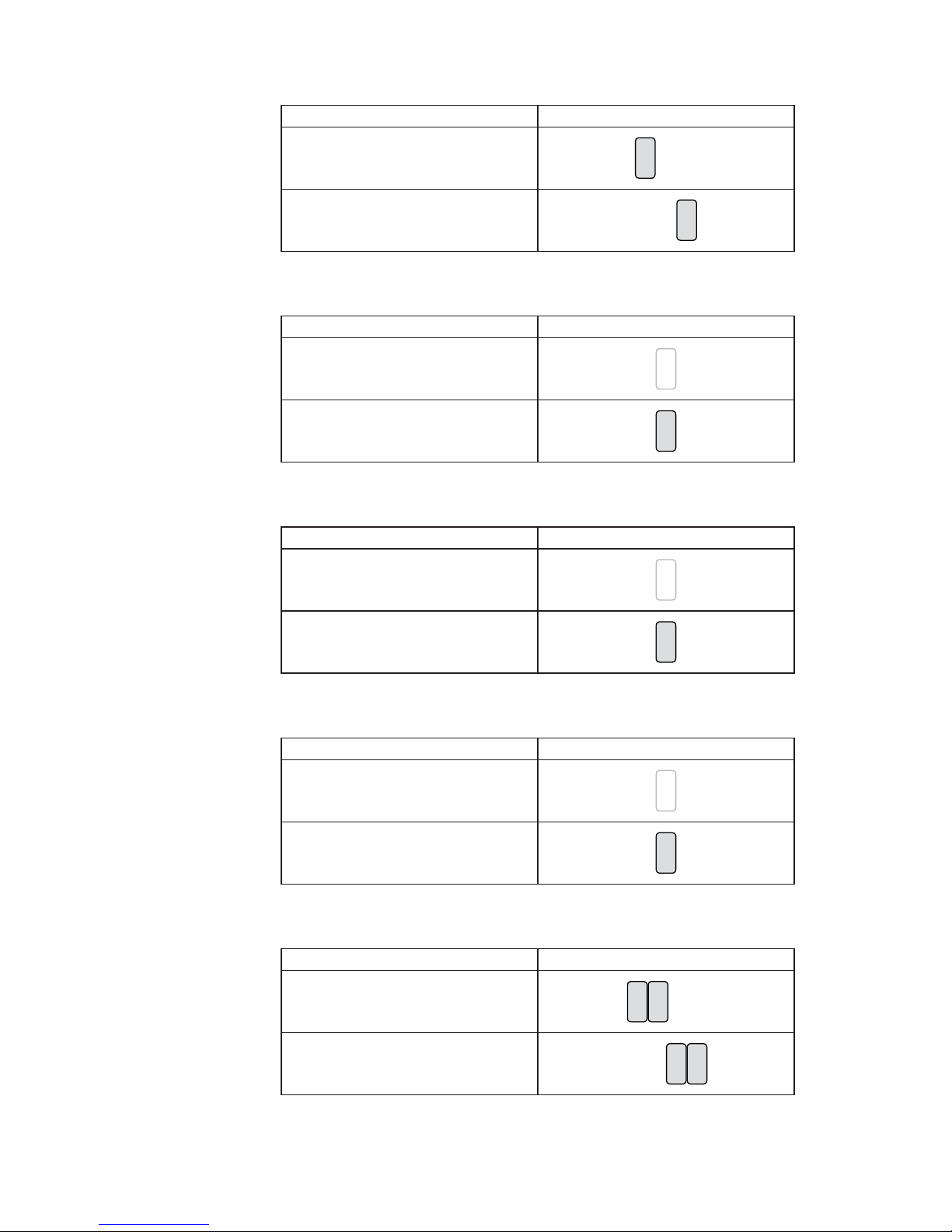
Jumper Setting6-2-3.
COM2 RS232/485/422 Setting
Function JP10 JP9
▲RS232
11
12810
579
2
13
64
579
2
13
68104
RS485
57911
2
13
6 8 10 124
810
579
2
1
3
64
RS422
10
57911
2
13
68 124
810
579
2
13
64
COM3 & COM4 Power Setting
Function JP3
COM3 Pin10
▲RI
57911
2
13
6 8 10 124
+5V
11
12810
579
2
13
64
+12V
11
12810
579
2
13
64
COM4 Pin10
▲RI
11
12810
579
2
13
64
+5V
11
12810
579
2
13
64
+12V
11
12810
579
2
13
64
▲ = Manufacturer Default Setting
Page 39
32
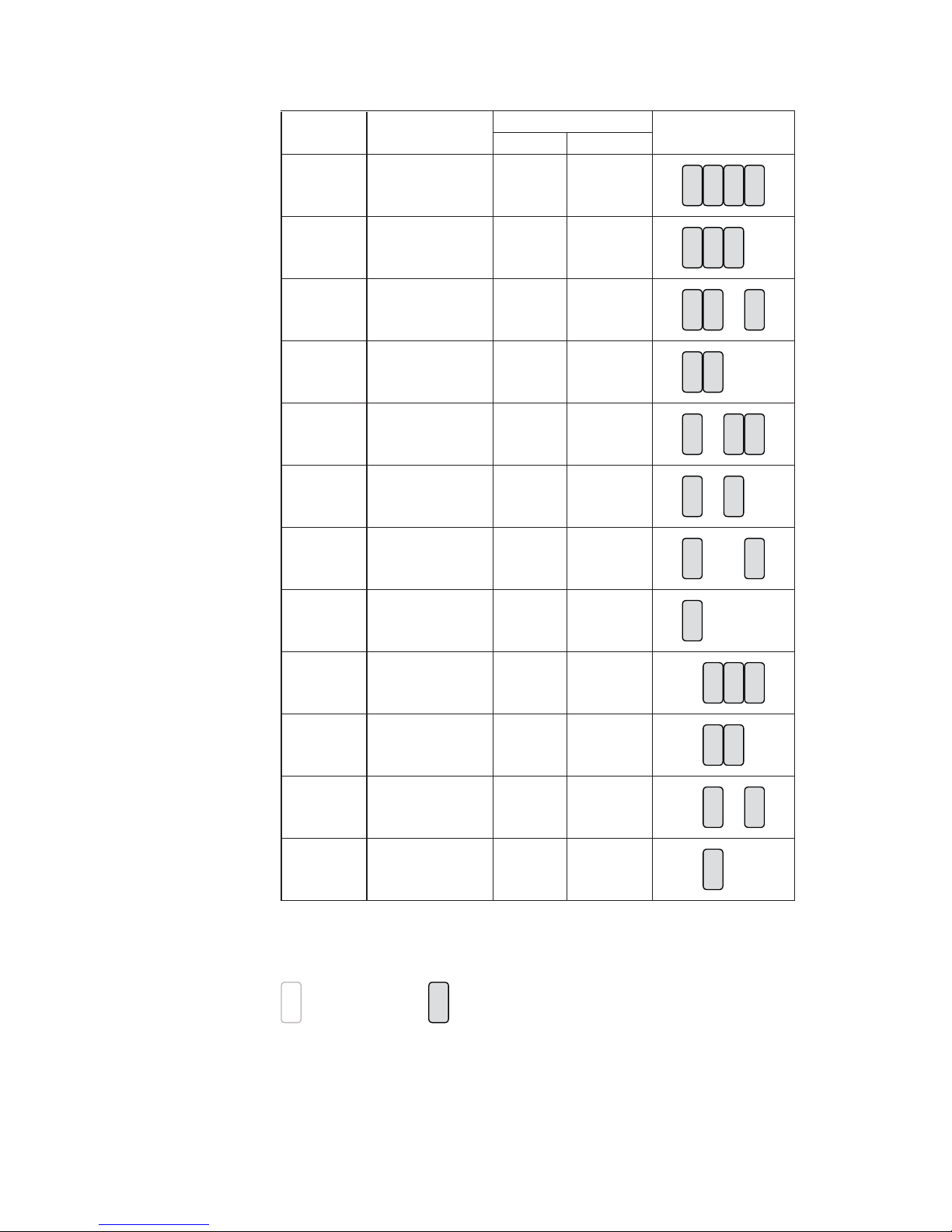
Cash Drawer Power Setting
Function JP4
▲+12V
5
2
13
64
+19V
5
2
13
64
Power Mode Setting
Function JP6
▲ATX Power
2
1
AT Power
2
1
CMOS Operation Mode
Function JP8
▲CMOS Normal
2
1
CMOS Reset
2
1
USB Path Setting
Function JP14
▲To Docking
2
1
To Motherboard
2
1
System Indicator Function
Function JP13
▲Disable
8
57
2
13
64
Enable
8
57
2
13
64
▲ = Manufacturer Default Setting
Page 40
33
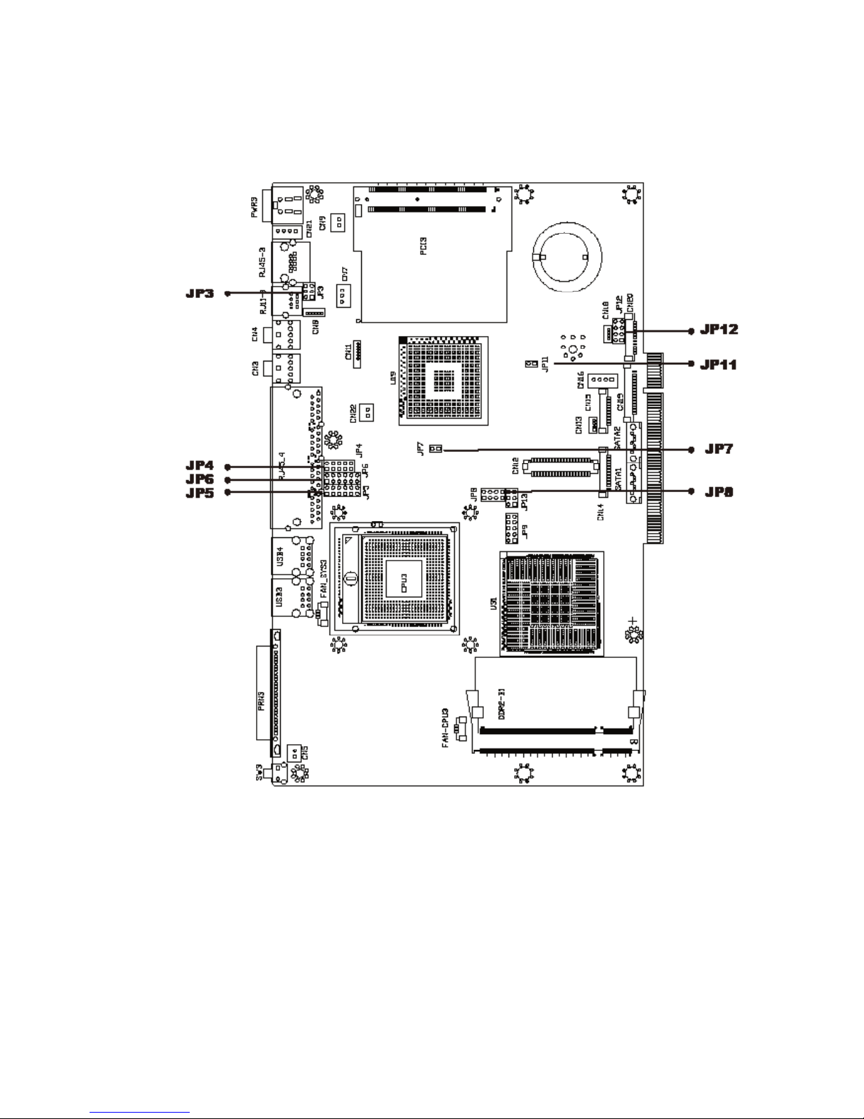
LCD ID Setting
Panel# Resolution
LVDS
JP7
Bits Channel
1 640 x 480 18 Single
8
57
2
13
64
2 800 x 600 18 Single
8
57
2
13
64
3 1024 x 768 18 Single
8
57
2
13
64
4 1280 x 1024 24 Dual
8
57
2
13
64
5 1024 x 768 24 Single
8
57
2
13
64
6 800 x 600 24 Single
8
57
2
13
64
7 800 x 600 18 Single
8
57
2
13
64
8 800 x 600 18 Single
8
57
2
13
64
9 1024 x 768 24 Single
8
57
2
13
64
10 1440 x 900 24 Dual
8
57
2
13
64
11 1280 x 1024 24 Dual
8
57
2
13
64
12 1440 x 900 18 Dual
8
57
2
13
64
Remark:
Panel ID#12 is specialized for Sharp 12.1" LQ121S1LG41/
LQ121S1LG42 panel
2
1
Jumper open
2
1
Jumper short
Page 41
34
Version: B98 v1.0
For B98 Motherboard
6-3.
Motherboard Layout6-3-1.
Page 42
35
Connectors & Functions6-3-2.
Connector Purpose
BAT3 CMOS Battery Base (Use CR2023)
CN3 Audio Line Out
CN4 MIC In
CN5 Internal Power On Switch Connector
CN8 Speaker & MIC Connector
CN9 Internal LAN LED
CN11 CD-IN / Line-In Connector
CN12 LCD Interface Connector
CN13 IrDA Connector
CN14 Inverter Connector
CN15 COM5 for Touch
CN16 Power Connector For HDD
CN18 USB5
CN19 Card Reader Connector
CN20 FT Status Interface Connector
CN21 Internal Input Power Connector
CN22 Hardware Reset
DDR2_A1 DDR2 SO-DIMM
DDR2_B1 DDR2 SO-DIMM
FAN_CPU3 CPU FAN Connector
FAN_SYS3 System FAN Connector
MINI_PCIE3 Mini PCI-E Socket
PCI3 Mini PCI Socket
PRN3 Parallel Port
PWR3 +19V Power Adaptor
RJ11_3 Cash Drawer Connector
RJ45_3 LAN (On Board)
RJ45_4 COM1, COM2, COM3, COM4
SATA1 SATA Connector
SATA2 SATA Connector
SKT1 SPI ROM
SW3 Power On Button
USB3 USB1, USB2
USB4 USB3, USB4
JP3 Cash Drawer Power Setting
JP4/JP6 COM2 RS232/485/422 Setting
JP5 COM3/COM4 Power Setting
JP7 CMOS Operation Mode
JP8 LCD ID Setting
JP9 VGA Port
JP10 2nd Display Power
JP11 Power Moder Setting
JP12 System Indicator
Page 43
36
Jumper Setting6-3-3.
COM2 RS232/485/422 Setting
Function JP6 JP4
▲RS232
57911
2
13
6 8 10 124
579
2
13
68104
RS485
11
12810
579
2
13
64
579
2
13
68104
RS422
10
57911
2
13
68 124
810
579
2
13
64
COM3 & COM4 Power Setting
Function JP5
COM3 Pin10
▲RI
57911
2
13
6 8 10 124
+5V
11
12810
579
2
13
64
+12V
11
12810
579
2
13
64
COM4 Pin10
▲RI
11
12810
579
2
13
64
+5V
11
12810
579
2
13
64
+12V
11
12810
579
2
13
64
▲ = Manufacturer Default Setting
Page 44
37
Cash Drawer Power Setting
Function JP3
▲+12V
5
2
13
64
+19V
5
2
13
64
Power Mode Setting
Function JP11
▲ATX Power
2
1
AT Power
2
1
CMOS Operation Mode
Function JP7
▲CMOS Normal
2
1
CMOS Reset
2
1
System Indicator
Function JP12
▲Disable
8
57
2
13
64
Enable
8
57
2
13
64
▲ = Manufacturer Default Setting
Page 45
38
LCD ID Setting
Panel# Resolution
LVDS
Output
Interface
JP8
Bits Channel
1 1366 x 768 24 Single
LVDS
Panel
8
57
2
13
64
2 1440 x 900 24 Dual
LVDS
Panel
8
57
2
13
64
4 1920 x 1080 24 Dual
LVDS
Panel
8
57
2
13
64
5 1024 x 768 24 Single
LVDS
Panel
8
57
2
13
64
6 1280 x 1024 24 Dual
LVDS
Panel
8
57
2
13
64
7 800 x 600 24 Single
LVDS
Panel
8
57
2
13
64
9 1024 x 768 18 Single
LVDS
Panel
8
57
2
13
64
11 800 x 600 18 Single
LVDS
Panel
8
57
2
13
64
12 800 x 600 18 Single
LVDS
Panel
8
57
2
13
64
CRT
8
57
2
13
64
Remark:
Panel ID#12 is specialized for Sharp 12.1" LQ121S1LG41/
LQ121S1LG42 panel
2
1
Jumper open
2
1
Jumper short
Page 46
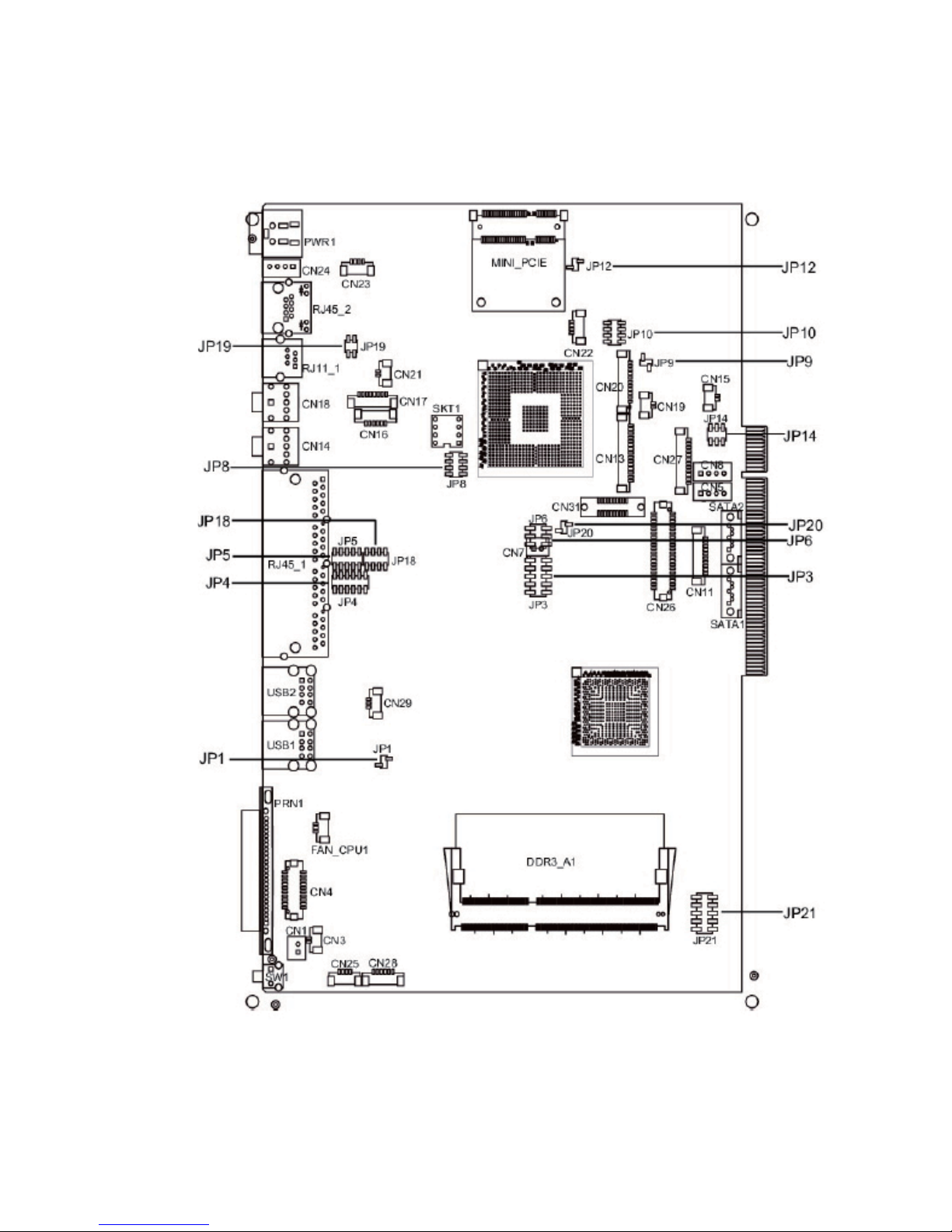
39
Version: C48 v2.1
For C48 Motherboard
6-4.
Motherboard Layout
6-4-1.
Page 47
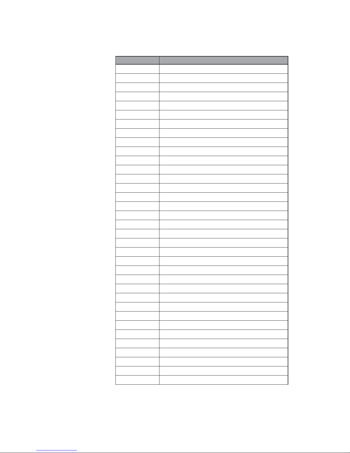
40
Connector Purpose
CN1 Power Button Connector
CN3 Printer Port Reset
CN4 Printer Port
CN5/8 HDD Power
CN11 COM5 For Touch
CN13 Card Reader Connector
CN14 Line out
CN15 HDD LED
CN16 Speaker & MIC
CN17 CD IN
CN18 MIC IN
CN19 Power LED
CN20/JP10 System Indicator
CN21 LAN LED
CN22 USB Port
CN23 PS2 KEYBOARD
CN24 +19V DC IN
CN25 For GM2621 Debug
CN26 LVDS
CN27 Inverter Connector
CN28 Key Pad
CN29 System Fan
DDR3_A1 DDR3 SO-DIMM1
SATA1 SATA Connector
SATA2 SATA Connector
SW1 Power Button
JP1 CMOS Operation Mode
JP3/6 VGA Port
JP4/5 COM2 RS232/485/422 Setting
JP8 LCD ID Setting
JP9 Power Mode Setting
JP12 System Reset
JP14 Inverter Selection
JP18 COM3/4 Power Setting
JP19 Cash Drawer Power Setting
Connectors & Functions
6-4-2.
Page 48
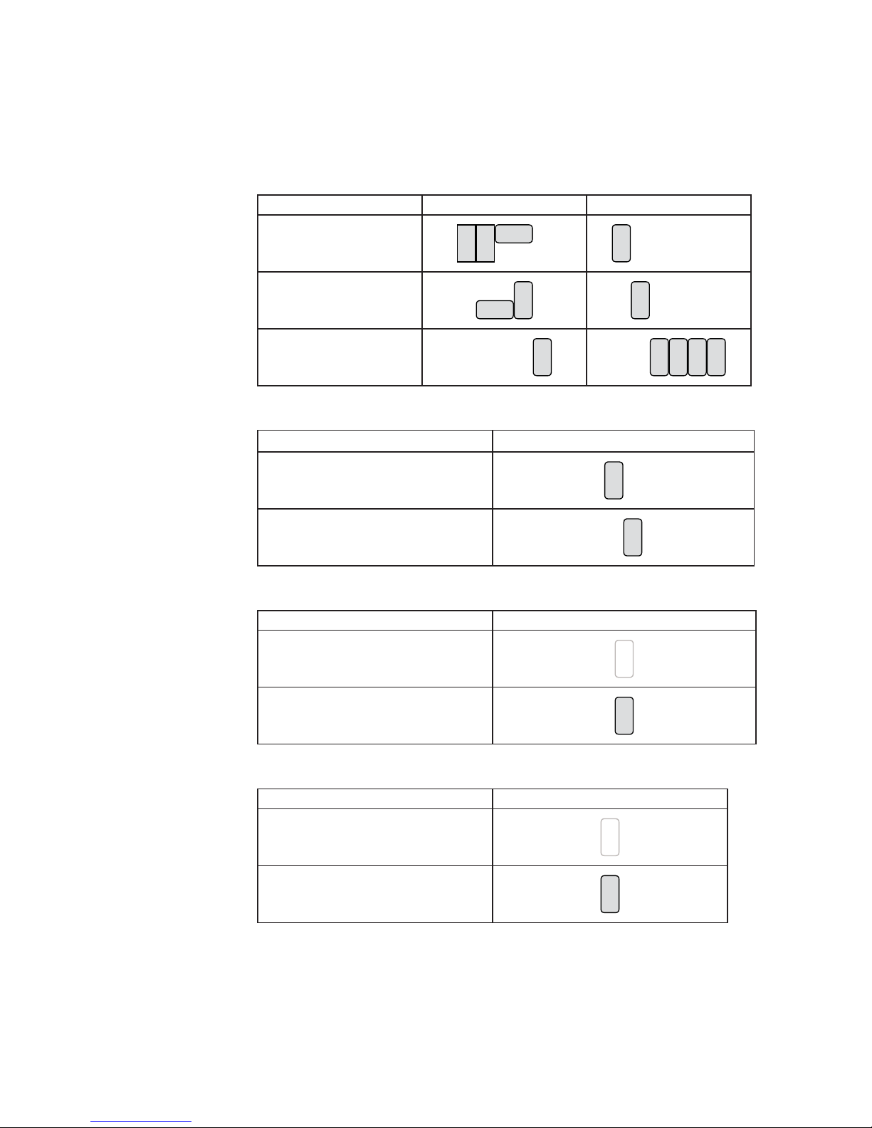
41
COM2 RS232/485/422 Setting
Function JP5 JP4
▲RS232
13579
268104
57911
2
13
6 8 10 124
RS485
810
579
2
1
3
64
11
12810
579
2
13
64
RS422
810
579
2
13
64 10
57911
2
13
68 124
Cash Drawer Power Setting
Function JP19
+19V
2
13
4
▲+12V
2
13
4
Power Mode Setting
Function JP9
▲ATX Power
2
1
AT Power
2
1
System Reset
Function JP12
▲System Normal
2
1
System Reset
2
1
▲ = Manufacturer Default Setting
Jumper Setting
6-4-3.
Page 49
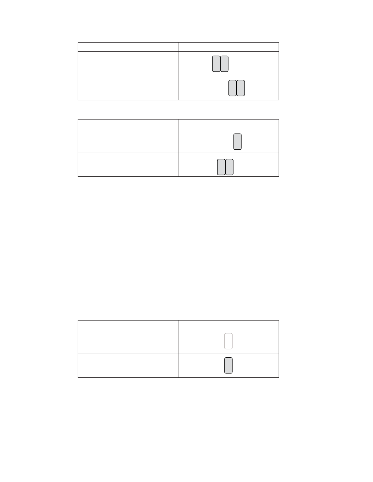
42
System Indicator
Function JP10
▲Disable
8
57
2
13
64
Enable
8
57
2
13
64
Inverter Selection
Function JP14
▲ CCFL
LED
CMOS Operation Mode
CMOS Reset
To clear the CMOS,
1. Remove the power cable from the system.
2. Open the system, and set the ‘CMOS Operation jumper’ from ‘CMOS Normal’
to ‘CMOS Reset’. (refer to the jumper shown below)
3. Connect the power cable to the system, and power on the system:
in ATX mode: press the power button and it will fail power on
in AT mode: turn on system power
4. Remove the power cable from the system.
5. Return the "CMOS Operation mode" jumper setting from "CMOS Reset" to
"CMOS normal".
6. Connect the power cable and power on the system.
Function JP1
▲CMOS Normal
2
1
CMOS Reset
2
1
▲ = Manufacturer Default Setting
5
2
13
64
5
2
13
64
Page 50
43
COM3 & COM4 Power Setting
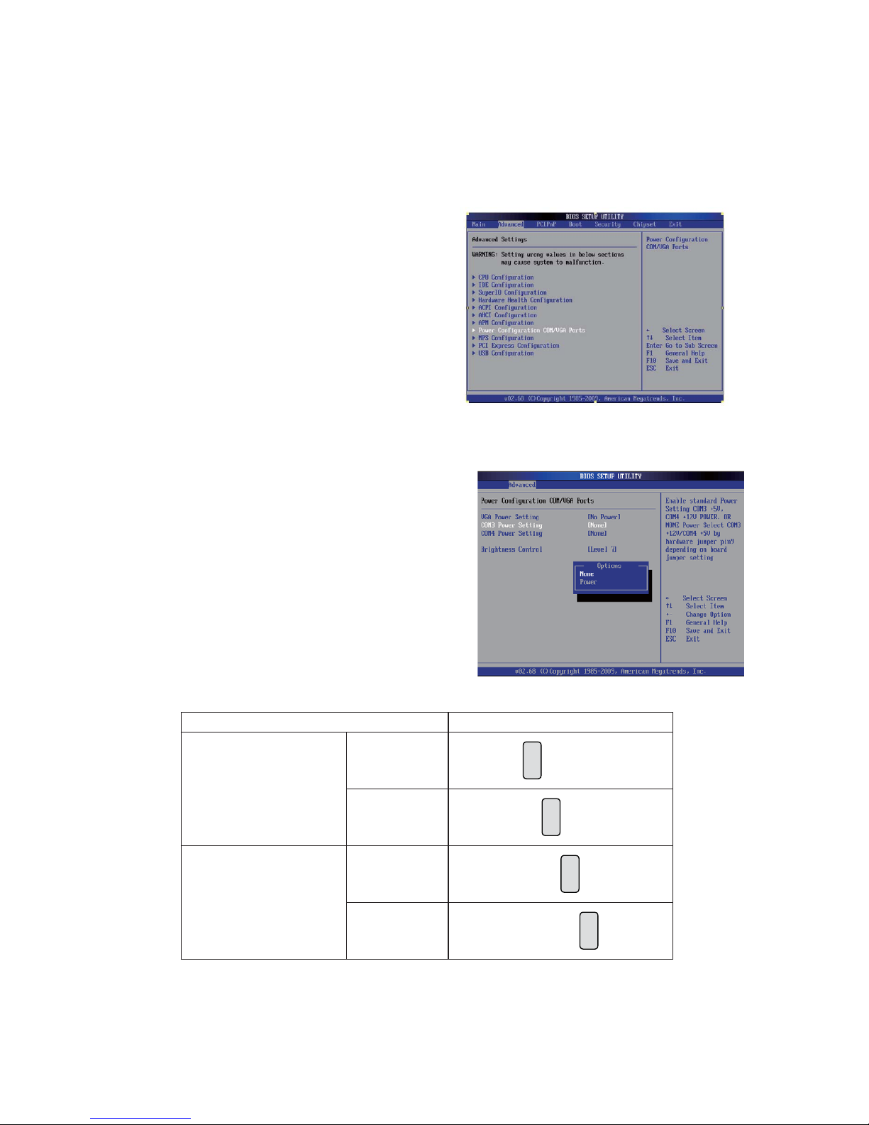
For C48, COM3/COM4 power adjustment must be made by BIOS/Utility and
Jumper. Since COM3/COM4 default is “None“ meaning no power, power must be
on through BIOS prior to physical jumper change.
Jumper setup
Function JP18
COM3
▲+5V
8
57
2
13
64
+12V
8
57
2
13
64
COM4
+5V
8
57
2
13
64
▲+12V
8
57
2
13
64
▲ = Manufacturer Default Setting
BIOS/Utility setup
Press <DEL> key to enter BIOS 1.
SETUP UTILITY when system
boot up.
Find tab "Advanced".2.
Select "Power Configuration 3.
COM/VGA Ports" and press
<Enter> to go to sub screen.
4. To switch on the power, select
"Power". Please save the
change before exiting BIOS
so as to go for physical jumper
adjustment.
Page 51
44
LCD ID Setting
Several configurations are applied to different sizes of panel. Please refer to the
followings to complete relevant settings.
12.1"/15" Terminal
Physical Jumper Setting
Resolution
LVDS
Output Interface JP8
Bits Channel
800 x 600 24 Single
1st: LCD Panel
2nd: VGA port
8
57
2
13
64
1024 x 768 24 Single
8
57
2
13
64
1366 x 768 24 Single
8
57
2
13
64
800 x 600 18 Single
8
57
2
13
64
*800 x 600 18 Single
8
57
2
13
64
1024 x 768 18 Single
8
57
2
13
64
Remark: Panel ID#12 is specialized for Sharp 12.1” LQ121S1LG41/
LQ121S1LG42 panel
2
1
Jumper open
2
1
Jumper short
2nd VGA Power Setting
VGA port power must be on through BIOS/Utility for default is “No Power“.
BIOS/Utility setup
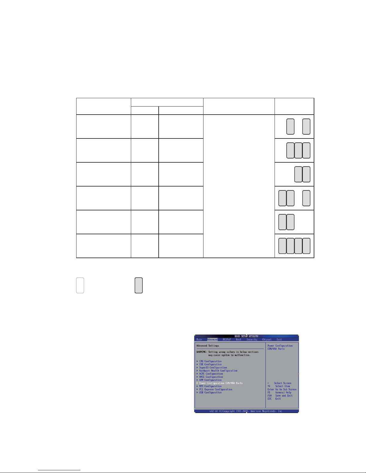
Press <DEL> key to enter BIOS 1.
SETUP UTILITY when system
boot up.
Find tab "Advanced".2.
Select "Power Configuration 3.
COM/VGA Ports" and press
<Enter> to go to sub screen.
Page 52
45
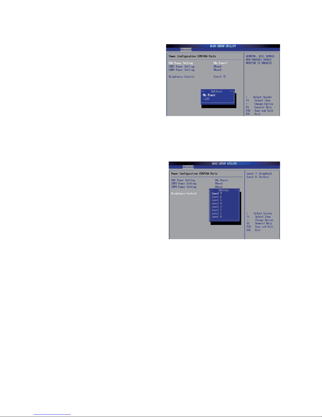
4. To switch on the power, select
"+12V". Please save the change
before exiting BIOS to avoid data
lost.
5. To switch brightness level, select
brightness control and choose
level. Please save the change
before exiting BIOS to avoid data
lost.
Page 53

46
Appendix: Drivers Installation
The shipping package includes a Driver CD in which you can find every individual
driver and utility that enables you to install the drivers on the system.
Please insert the Driver CD into the drive and double click on the “index.htm” to
select the models. You can refer to the drivers installation guide for each driver in
the “Driver/Manual List”.
 Loading...