

Page 1

InstalationIn
SECTION/ELEVATION
FOR SERVICE.
COILED BELOW FIXTURE
LEAVE 18" MIN. LOOP
WITH FX LITESPLICE.
LOW VOLTAGE CABLE
FINISHED GRADE
AND DIRT TO DRAIN OFF LENS CAP.
OFF VERTICAL TO ALLOW WATER
AIM FIXTURE A MINIMUM OF 10˚
SPREAD, AND ACCESSORIES.
SEE PLAN LEGEND FOR WATTAGE, BEAM
FX LUMINAIRE LUSTRO RAME FIXTURE.
C 2004 FX LUMINAIRE
ø2.40"
6.50"
8.00"
LUSTRO RAME (LR)
FX LUMINAIRE - SPIKEMOUNT
SCALE: NOT TO SCALE
INSTALLATION NOTES
We have developed this series of field installation guidelines to assit you in correctly installing
fixtures and transformers ensuring customer satisfaction and trouble free service. If you have
any questions please call your local distributor or the FX Techline at 800-688-1269 before
proceeding. Follow all NEC guidelines and local electrical codes.
For further info, see our website: www.FXL.com
SAVE THESE INSTRUCTIONS
LR: LustroRame
This product is an Uplight only.
Standard Spike Mount
Do not use as a Downlight.
For a complete listing of
installation details go to
www.fxl.com/learning/
installation_notes.htm
Why use the LiteSplice?
Without a waterproof splice connection any
system will develop voltage loss and low grade
shorts making your lighting professional life hell.
Below is our proven method of insuring you and
your client years of trouble free high performance
from the FX System.
FX Does NOT recommend the use of Quick
Clip style connectors or Pre-filled wirenuts
because they are not waterproof and will
rot out creating resistance and shorts. A
little more time spent during installation
is repaid handsomely in reduced service
calls.
Step 1
Begin with a 12, 10 or 8 gauge direct burial low
voltage cable mainline. (Use stranded 12 gauge
THHN (120v style) wire for conduit runs such as
wall lights or trellis lights).
Step 2
Cut the mainline cable in half and strip back
3/4” of the insulation from each side to expose
the multi-stranded copper conductor.
RISK OF FIRE WARNING:
DO NOT USE FX FIXTURES WITH ANY
STYLE OF TRANSFORMER THAT EXCEEDS
14 VOLTS ON THE SECONDARY.
Installation Guidelines:
DO NOT EXCEED 50 WATTS IN THIS FIXTURE
The main secondary wiring is intended for shallow burial - less thank 6 inches (152mm). This fixture
should not be installed within 10 feet (1.42m) of a pool, spa or fountain. To relamp, turn lens cap as if
it is threaded, remove lamp and carefully insert new one. Do not touch the actual lamp bud with fingers
as this will shorten lamp life. If you do touch lamp bud, clean off with cloth and alcohol. Apply hi-temp
dilectric grease into socket to prevent moisture damage to lamp base. To install cap start it on an angle
so it’s halfway on, then twist and push down as if it was threaded. Lens cap can be lubricated on inside
to ease installation. To minimize clean-up, keep plastic shipping bag on fixture until just before system
testing.
Eve Mount: Mount as high as possible to allow maximum beam projection. To minimize glare, keep
the aiming angle 60° to vertical. Conceal fixtures and cables between beams whenever possible. The
12-16 gauge feed wire should be attached with either nyulon C-clamps with stainless screws or plated
staples. For high performance and predictable lamp life, supply fixture with between 11 - 11.5 volts
with all lamps installed and operating. USE FX LUMINAIRE TRANFORMERS ONLY — FX WILL NOT
WARRANTY OR REPLACE ANY COMPONENTS DAMAGED BY OTHER MANUFACTURER’S EQUIPMENT. The FX transformer is specifically designed for the high tech lamps used in our fixtures —the use
of inferior power supplies can cause premature lamp failure and other problems including the risk of fire.
To order connectors or additional lengths of wire for connection, contact your local distributor.
IMPORTANT SAFETY INSTRUCTIONS: WARNING! TO REDUCE RISK OF FIRE OR INJURY TO PERSONS: Turn off/ unplug and allow to cool before replacing lamp — lamp gets HOT quickly! Contact
only switch/plug when turing on. Do not touch hot lens, guard or enclosure (*See drawing for location
of lens). Keep away from materials that may burn. Do not touch the lamp at any time. Use soft cloth. Oil
from skin may damage lamp. Do not operate the luminaire fitting with
For 50w LR: Lighted lamp is HOT!
missiong or damaged sheild.
Step 3
Join one of the fixture’s conductors to each side
of the mainline as shown in the diagram. Since
there is no polarity in low voltage, it doesn’t matter which side is which when joining the conductors together. Install a wirenut on each side. Now
is the time to test the individual circuits (cables)
for voltage drop. If you were a good boy and
followed the Circuiting Guidelines included with
the FX MultiTap Transformer you should be able
to provide each fixture with between 10.5 - 11.5
volts with all lamps installed and operating. Test
now before you install the SpliceGel because it’s
easier to stick the VoltMeter’s probes inside the
wirenuts to get a reading.
Step 4
Pump about two squeezes of SpliceGel into the
baggie and insert both wirenut connections into
it. Push out the air and work the Gel into the
bottom of the wirenut assuring a waterproof connection. Install the cable tie as shown and cinch
down to complete the most cost effective permanent waterproof low voltage connection known
to man. The Gel will set-up rock hard in about
3 days. It’s best to leave 12-18” of slack at each
fixture to allow for relocation or if you need to
splice in additional cables in the future. Since
this is a permanent splice solution — you will
need to cut it off and start from scratch to add
cables to the splice.
Step 4Step 3
Page 2
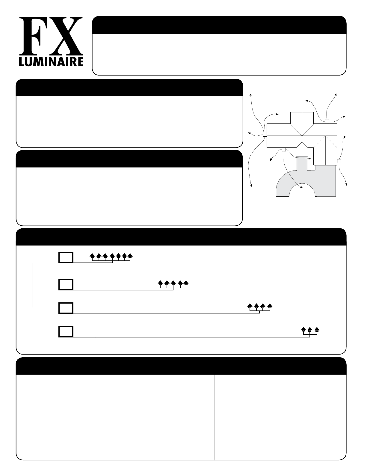
SYSTEM LAYOUT
T
Custom
Home
T
T
T
We have developed this series of field installation guidelines to assist you in correctly
installing fixtures and transformers insuring customer satisfaction and trouble free service.
If you have any questions please call your local distributor or the FX TechLine at
800-688-1269 before proceeding. Follow all NEC guidelines and local electrical codes.
WWW.FXL.COM
Single Transformer:
When using only one transformer, it is very important to center the transformer on the wattage
load. If the project calls for 135 watts in both front and back yard, the PX-300 or PX-600 should
be centered on the side of the house that will receive the most lighting. A common mistake is to
locate the single transformer on the service side of the house or in the garage, which might result
in excessively long cable runs to reach lighted areas. The primary goal in laying out low voltage
systems is to minimize cable runs because of the negative effect voltage drop has on lamp output
performance.
Multiple Transformers:
A common mistake in laying out multiple transformer circuits is to group several transformers in
one location because of utility or visual considerations only. As with any low voltage layout, the
prime directive should be to locate the transformers as close to the fixtures as possible in order to
minimize cable runs and resulting voltage drop. The other multi-transformer layout consideration is
“use zoning”. Having several transformers allows the client to selectively control light in separate
areas. This approach is similar to irrigation design in that the goal is to individually control areas
that have similar needs. In lighting, a recreation area has different lighting needs than does a front
entry. Therefore, the lights that serve these different lighting use areas need to be on separate
transformers and switch controls.
For further info see our website: www.FXL.com
Sample diagram of home with transformer
and lamp placement
Circuiting Guidelines:
T
Close-Zone 0-40’
12 Gauge-160 watts max. 10 Gauge- 220 watts max. 8 Gauge 280 watts max.
T
Mid-Zone 40-80’
12 Gauge-120 watts max. 10 Gauge- 200 watts max. 8 Gauge 280 watts max.
T
Far-Zone 80-120’
12 Gauge- 80 watts max. 10 Gauge- 140 watts max. 8 Gauge 200 watts max.
Loads PER CABLE
Add cable runs as necessary
T
Out There-Zone 120-160’
12 Gauge-60 watts max. 10 Gauge- 100 watts max. 8 Gauge 160 watts max.
Lamp Life:
• Lamp life is rated in hours of operation. If lamps are rated for 4000 hours
at 12 volts it means that at 4000 hours, 50% of the lamps are still work
ing and 50% are not.
• For maximum light output, tune lighting circuits to provide between 11.5
and 12.0 volts as measured at lamp terminals when all of the lamps on
the circuit are operating.
• For longer lamp life, adjust voltage down so lamps receive between 10.5
and 11.5 volts at the lamp terminals.
• Voltage can be regulated by adjusting circuit load/run by using FX Po
tenxaX Transformers.
• To determine circuit voltage, use FX Digital Voltmeter.
Volts at
Lamp
13.0*
12.5*
12.0
11.5
11.0
10.5
10.0
* This voltage is not recommended
Lamp Life
of Rate
50%
75%
100%
200%
300%
500%
900%
Lumen Output
of Rated
350%
175%
100%
80%
75%
65%
50%
 Loading...