


Series S1501 Selectronic®
Micro-Controller/Annunciator
Model Year 2011 and Earlier
Installation and Operations Manual
00-02-0271
2018-10-23
Section 50

Please read the following information before installing.
BEFORE BEGINNING INSTALLATION OF THIS FW MURPHY
PRODUCT:
Read and follow all installation instructions.
A visual inspection of this product before installation for any
damage during shipping is recommended.
Disconnect all electrical power to the machine.
Make sure the machine cannot operate during installation.
Follow all safety warnings of the machine manufacturer.
Please contact FW MURPHY immediately if you have any
questions.
In order to consistently bring you the highest quality, full-featured products, we reserve the right to change our
specifications and designs at any time. The latest version of this manual can be found at www.fwmurphy.com.

Table of Contents
Product Description ................................................................................................................... 1
Installation ................................................................................................................................... 4
Mounting Dimensions ...................................................................................................4
Typical Hazardous Areas Installation ...........................................................................6
S1501 System - Typical Hook Up ................................................................................7
Power Supply – Typical Wiring Diagram .................................................................... 11
Operation ...................................................................................................................................12
Operating the S1501 Interface ................................................................................... 12
Sequence of Operations - Engine Mode .................................................................... 13
Sequence of Operations – Motor Mode ..................................................................... 15
System Set Up Menus ............................................................................................... 17
Editing System Set Up ............................................................................................... 18
Troubleshooting .......................................................................................................................25
Specifications ...........................................................................................................................27
Replacement Parts and Accessories ....................................................................................28

(THIS PAGE INTENTIONALLY LEFT BLANK)

Product Description
The Series S1501 system is a microprocessor based alarm, shutdown, and control system
with tachometer/hourmeter function. It tells in alphanumeric characters which protective device
has signaled an alarm or caused equipment shutdown. Application programming is completed
at Murphy and can be changed in the field.
The system consists of:
S1501 Head
Power Supply - explosion proof
Terminal Block Assembly, rail mount type, accommodates 32 sensors (2 needed for 64
sensor models)
Flat Ribbon Cable - 36 inch (914 mm) to connect the terminal block to the head.
The S1501 is powered from 120 VAC or 12/24 VDC. It is approved for Class I, Div. 1, Groups
C & D areas.
S1501 Head
The Head is the brain of the micro-controller system. It contains a microcomputer, an
alphanumeric display and keypad for operator access to field adjustable functions, and a
communication port: RS232 or RS485 (Modbus RTU slave). This port allows for remote
control functions such as Start/Stop, Load/Unload, etc., and for access to S1501 data
registers.
Alphanumeric Display
The S1501 Head displays each mode of operation. The display is a dot matrix alphanumeric
32-character display arranged in two lines (each with 16 characters). By observing the monitor,
the operator can determine the operating status of the control system.
Power Supply
An explosion-proof enclosure designed for Class I, Division 1, Groups C & D hazardous
locations contains the supply voltage conditioning circuits, head power supply, and the
intrinsically safe barriers for isolation between the power supply and the low energy head
circuits. The power supply accepts 120 VAC, 50-60 Hz and/or 12-24 VDC input power.
12-24 VDC power can be used as primary power or as a backup source of power when
120 VAC is used.
Section 50 00-02-0271
2018-10-23 - 1 -

Control Relays
The power supply has seven control relays to provide form “C” SPDT outputs for control
functions of either the engine or electric motor application.
Terminal Block Assembly
Each sensor input terminal block consists of a 64-position, 32 pair input rail-mount terminal
block for interface of panel or field-mounted end devices. For Class I Division 1 areas, end
devices must be non-energy storing devices, such as mechanical switches with dry contacts.
The terminal block is used for Normally Open sensors (one wire close to ground), and/or
Normally Closed sensors (two wires).
Ribbon Cable
A 36 in. (914 mm) flat ribbon cable is required for connection of the S1501 head and the
sensor input terminal block. The cable is supplied with two D-sub 37 PIN connectors at each
end of the cable.
Power and Control Cable
The S1501 is connected to the power supply via the Power and Control Cable
(15-conductor shielded cable, 72 in. [1.81 m] long). The cable is factory-sealed on the power
supply end, and has a 15-pin, D-sub connector on the S1501 Head end.
Sensor Inputs
User-selectable Sensor Input types (Shutdown or Alarm Only) are available for each sensor.
The sensor inputs are identified as follows:
Class A: Inputs are operative (armed) all the time.
Class B1: Inputs are enabled after the first preset Start-Run time period.
Class B2: Inputs are enabled after the second preset Start-Run time period.
Class C: Inputs are armed after the fault has been cleared for 2 seconds.
Class P: Armed after the Load Relay has exergized and the process time has expired.
Class ESD: Emergency Stop overrides the test lockout timer.
Permissive Function
This function was designed to monitor pre-lube pressure input. Terminal 32 of the sensor
terminal block is reserved for a permissive pre-lube input. The pressure signal can be obtained
from a pressure switch with normally open or normally closed contacts that indicates whether
or not sufficient oil pressure has been reached during pre-lubing. If permissive pressure has
not been reached, the system will not allow start-up. If the Permissive Function is not required,
install a wire jumper in Terminal 32 and set the Permissive Timer setting at zero.
Section 50 00-02-0271
2018-10-23 - 2 -

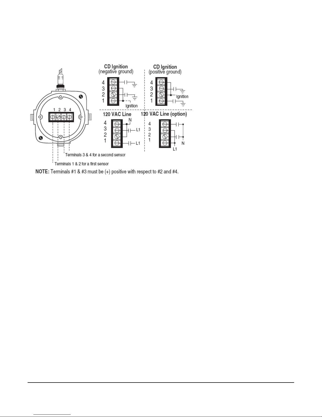
Opto-Isolated Tach/Run Input
The S1501 features an opto-isolated tach/run input located within the explosion-proof power
supply. This special input is used for Run Input Sensing from a CD ignition, Magnetic Pickup,
Motor Auxiliary Signal, or AC or DC run signals meeting the opto-isolated Tach/Run input
specifications (refer to the Specifications section of this manual).
NOTE: For tachometer sensing a magnetic pickup is recommended.
Built-In Barrier (within the Power Supply)
The S1501 power supply circuit is isolated from the Head by the intrinsically safe barrier
located on the printed circuit board (power supply enclosure), between the power supply
output and the power and control cable terminal block.
A fuse barrier mounted inside the Power Supply isolates the power output to the Head. Zener
diode shunt barriers isolate the seven control outputs from the Head.
Hourmeter
A hourmeter feature is available for the S1501 to record the engine or motor elapsed running
time.
Section 50 00-02-0271
2018-10-23 - 3 -

Installation
WARNING: Perform the mounting operation with power source off.
The S1501 Head was designed to be mounted within a
weatherproof enclosure. It is intended for mounting in a flat panel.
First, cut a square mounting hole of 3-5/8 in. (92 mm) x 3-5/8 in. (92 mm).
Insert the Head from the front side of the panel and install the two mounting clamps, one on
each side of the case, (see mounting clamp detail).
Secure the unit to the panel by tightening the clamps with a blade type screwdriver.
Mounting Dimensions
Section 50 00-02-0271
2018-10-23 - 4 -

Section 50 00-02-0271
2018-10-23 - 5 -

Typical Hazardous Areas Installation
WARNING: FOR HAZARDOUS APPLICATION REQUIREMENTS, THE
S1501 COMPLETE SYSTEM MUST BE INSTALLED IN ACCORDANCE
WITH THE NATIONAL ELECTRICAL CODE (NEC) CLASS I, DIVISION
1, GROUP D (ARTICLE 504) SPECIFICATIONS. SENSOR INPUT
WIRES MUST BE SEPARATED A MINIMUM OF 2 IN. (51 MM) FROM
OTHER WIRES. USE OF SENSOR INPUT WIRE TYPE CONDUIT IS
RECOMMENDED.
Section 50 00-02-0271
2018-10-23 - 6 -

S1501 System - Typical Hook Up
WARNING: PERFORM THE WIRING OPERATION WITH THE POWER
SOURCE “OFF” AND THE AREA MADE NON-HAZARDOUS. MAKE
SURE THE VOLTAGE AND CURRENT REQUIREMENTS ARE WITHIN
THE S1501 SYSTEM RATINGS. CONDUIT IS REQUIRED TO
PROTECT WIRES FROM DAMAGE. REFER TO THE SPECIFIC
SYSTEM APPLICATION WIRING DIAGRAM SUPPLIED WITH YOUR
UNIT.
Head Connections
a. Interconnect the S1501 head and the power supply with the power and control cable,
secure the connector in place by tightening the screws on each side of the connector.
b. Repeat step (a.) for the RS232/RS485 serial port (if applicable).
c. The sensor input connector(s) from the terminal block(s) plugs into the back of the
Head. Secure by tightening the screws on each side of the connector.
Section 50 00-02-0271
2018-10-23 - 7 -

Typical Power Supply Connections
WARNING: Do NOT route the power supply wiring and the sensor
input lead wiring in the same conduit.
a. Conduit installation:
1) Remove power before opening power supply cover.
2) Install one 1/2 in. NPT or two 3/4 in. NPT conduits, from customer end of the Power
Supply.
Note: Follow NEC guidelines for maximum number of wires in conduit.
3) Install an approved explosion-proof seal in the conduit within 18 in. (457 mm) of
Power Supply enclosure (seal unused conduit holes).
Important: Green screw above conduit hole (power supply) is to attach
equipment ground per NEC.
b. Customer Installed Field Wiring: Install wiring to power supply through conduit
installed in “step 2-a”.
1) Run wiring from the power source to the S1501 power supply.
2) Connect the 120 VAC to the two AC Power Input terminals. Connect equipment
ground to green screw (see schematic below).
3) Connect the 12 or 24 VDC Positive (+) lead to Power Input terminal 12-24 DC.
4) Connect 12 or 24 VDC “DC(–)” lead to the GND terminal. (See “Power Supply
Typical Wiring Diagram”.)
Section 50 00-02-0271
2018-10-23 - 8 -

Normally Open Sensor Input Wiring
Wire each normally open sensor on top of the factory-supplied jumper. Loosen the screw and
slide the wire lead into the terminal without removing the jumper (either side of jumper).
Normally Closed Sensor Input Wiring
Remove the factory-supplied jumper completely. Connect the two sides of the normally closed
sensor to the two terminals of the terminal block.
NOTE: Switches connected to the S1501 Sensor Input Terminal Block
must be dry contact mechanical switches.
Intrinsically Safe Barrier Wiring
Important (normally open sensor only): Secure area of hazardous
conditions before opening barrier cover or operating sensor contacts.
a. Run Sensor switches wiring through conduit and isolate from the S1501 terminal
block(s) with an explosion-proof barrier.
b. For wiring refer to the following typical wiring diagrams.
Section 50 00-02-0271
2018-10-23 - 9 -
Normally Open System Barrier
LCDT-ISB barrier (optional)
Normally Closed System Barrier
For normally closed non-intrinsically safe sensors, use an approved intrinsically safe barrier,
and wire according to manufacturer’s instructions.
Section 50 00-02-0271
2018-10-23 - 10 -
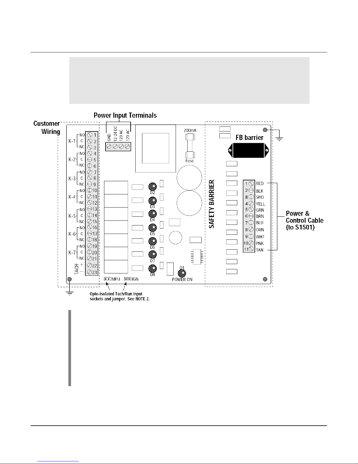
Power Supply – Typical Wiring Diagram
WARNING: Perform the wiring operation with the power source
“OFF” and the area made non-hazardous. Make sure the voltage
and current requirements are within the S1501 system ratings.
Conduit is required to protect wires from damage. Refer to the
specific system application wiring diagram supplied with your unit.
NOTE 1: K-1 thru K-7 are relay outputs form “C” dry contacts.
D1 thru D8 are LED indicators.
D1= POWER ON;
D2=K1; D3=K2; D4=K3; D5=K4; D6=K5; D7=K6; D8=K7.
NOTE 2: Opto-isolated tach/run input jumper is shipped in the IGN
position. IGN socket is used for negative or positive ground type CD
ignitions. MPU socket is used for magnetic pickup or motor starter
auxiliary contact not to exceed 120 Vrms.
Section 50 00-02-0271
2018-10-23 - 11 -

Operation
Operating the S1501 Interface
Use the six membrane keys to scroll throughout the menus and to make changes to the
System timers, Tachometer calibration, Overspeed, Underspeed, Run Hourmeter (ETM), and
Sensor Setup..
YES - key used for scrolling up (increment).
NO - key used for scrolling down (decrement).
RESET - key used to reset alarms or shutdowns.
MODE - key used for mode and test time modes.
START/STOP – key used for Local mode start and stop signals.
ENTER - key used for entering/confirming set points and exiting menus
Section 50 00-02-0271
2018-10-23 - 12 -

ENGINE APPLICATION
EVENT
DISPLAY
RELAY
K1
K2
K3
K4
K5
K6
K7
Lube
Crank
Ign.
Fuel
Load
Alar
m
SD
WAITING ON START
Unit monitors for a valid start signal. Shutdown and
Alarm relays are energized. * User can at this time,
press the Mode key to modify desired setup tables.
Class A inputs are scanned.
Waiting On Start
ETM: xxxxx.x hrs
Off
Off
Off
Off
Off
On
On
Start signal received. Unit advances to Prelube cycle.
Waiting On Start
ETM: xxxxx.x hrs
Off
Off
Off
On
Off
On
On
If an RPM signal is seen before the Start signal is
pressed, a fault occurs.
Unexpected
Engine Start!
Off
Off
Off
On
Off
Off
Off
PRELUBE CYCLE
Prelube cycle begins. Permissive timer starts. Lube
relay energized.
LUBE CYCLE...
Permissive x:xx
On
Off
Off
Off
Off
On
On
Permissive time expires before Permissive signal* seen
closed. Fault occurs. Lube relay is de-energized.
Permissive
Failure
Off
Off
Off
Off
Off
Off
Off
Permissive signal closed. Prelube Cycle timer started.
LUBE CYCLE...
Prelube x:xx
On
Off
Off
Off
Off
On
On
Prelube Cycle timer times down to zero. Unit advances
to Crank cycle.
LUBE CYCLE...
Prelube :00
On
Off
Off
Off
Off
On
On
CRANK CYCLE
Crank Relay energizes. If the Run Delay Preset is > 0,
the controller will wait for a Crank RPM permissive to
proceed. If set to 0, this cycle is skipped
CRANK PERMISS...
Run Delay x:xx
On
On
Off
Off
Off
On
On
Run Delay time expires before RPM > 10 is seen. Fault
occurs.
Engine Failure To
Crank!
Off
Off
Off
Off
Off
Off
Off
RPM > 10 is seen, or Crank Permissive cycle skipped.
Cranking continues with purge timer started at preset
time.
CRANK CYCLE...
Purge :xx
On
On
Off
Off
Off
On
On
Purge delay expires. Ignition relay is energized. Fuel
On delay is started.
CRANK CYCLE...
Fuel Delay :xx
On
On
On
Off
Off
On
On
Fuel On delay expires. Fuel relay energized. Crank
timer started. The Controller will monitor for a Crank
Disconnect RPM to advance to the Run Cycle.
CRANK CYCLE...
Crank :xx
On
On
On
On
Off
On
On
Crank timer expires before disconnect speed is
reached. Unit goes into Rest cycle. Crank, Ignition, and
Fuel relays are de-energized. When the Rest expires,
the Crank Cycle will repeat.
CRANK CYCLE...
Rest :xx
On
Off
Off
Off
Off
On
On
All crank attempts exhausted. Crank timer expires.
Disconnect speed not reached. Overcrank condition
occurs. All relays de-energized.
Overcrank
Shutdown!
Off
Off
Off
Off
Off
Off
Off
Sequence of Operations - Engine Mode
Section 50 00-02-0271
2018-10-23 - 13 -

K1
K2
K3
K4
K5
K6
K7
Lube
Crank
Ign.
Fuel
Load
ALM
SD
RUN CYCLE
Crank Disconnect RPM reached. Crank relay deenergized. Class B1 Lockout, B2 Lockout and Load
timers started. Class C shutdowns are allowed to arm.
Speed: xxxxrpm
Class-B1 x:xx
Off
Off
On
On
Off
On
On
Class B1 and B2 Lockout timers expire. Elapsed time
displayed. Unit monitors for stop condition.
Speed: xxxxrpm
ETM: xxxxx.x hrs
Off
Off
On
On
Off
On
On
Load timer expires. Load relay energized. Process
Lockout timer starts. When this timer expires, Class P
shutdowns will be armed. User can press the Mode key
to initiate the Test timer and test sensor inputs.
Speed: xxxxrpm
Test Timer 5:00
Off
Off
On
On
On
On
On
IDLE CYCLE
Stop signal is seen. Load relay is de-energized. Class
P shutdowns are disarmed. Idle timer is started.
Speed: xxxxrpm
Idle x:xx
Off
Off
On
On
Off
On
On
ALARM FAULT
Alarm only input faulted. Alarm relay de-energized.
Fault alternately displayed with previous message
displaying the speed and run hours.
Low Coolant
Level
Off
Off
On
On
On
Off
On
S1501 Reset key pressed. Alarm relay is picked up.
Unit continues to scans for fault or stop condition.
Speed: xxxxrpm
ETM: xxxxx.x hrs
Off
Off
On
On
On
On
On
FAULT SHUTDOWN
Unit receives a fault at sensor #4 for instance. The Fuel
Valve, Alarm, and Shutdown relays are de-energized.
Speed: xxxxrpm
Ign. Gnd. :xx
Off
Off
On
Off
Off
Off
Off
Ignition ground delay expires. Ignition relay deenergized. Postlube cycle begins. Lube relay
energized.
LUBE CYCLE...
Postlube x:xx
On
Off
Off
Off
Off
Off
Off
Postlube expires. Lube relay de-energized. Fault is
displayed.
Low Compressor
Oil Pressure
Off
Off
Off
Off
Off
Off
Off
S1501 Mode key pressed. Shutdown type displayed.
Sensor Input #04
Class B1,Shutdown
Off
Off
Off
Off
Off
Off
Off
S1501 Reset key pressed. Unit waiting on start input.
Waiting On Start
ETM: xxxxx.x hrs
Off
Off
Off
Off
Off
On
On
NORMAL STOP (AFTER IDLE CYCLE)
Stop signal received and idle timer expired. Ignition
ground delay begins. Fuel Valve relay de-energized.
Speed: xxxxrpm
Ign. Gnd. :xx
Off
Off
On
Off
Off
On
On
Ignition ground delay expires. Ignition relay deenergized. Postlube cycle begins. Lube relay
energized.
LUBE CYCLE...
Postlube x:xx
On
Off
Off
Off
Off
On
On
Postlube cycle timer expires. The Lube relay is deenergized. Unit returns to Waiting on Start.
Waiting On Start
ETM: xxxxx.x hrs
Off
Off
Off
Off
Off
On
On
Section 50 00-02-0271
2018-10-23 - 14 -

ELECTRIC MOTOR APPLICATION
EVENT
DISPLAY
RELAY
K1
K2
K3
K4
K5
K6
K7
Lube
Not
Used
Motor
Cooler
Load
Alarm
SD
WAITING ON START
Unit monitors for a valid start signal. Shutdown and
Alarm relays are energized. * User can at this time,
press the Mode key to modify desired setup tables.
Class A inputs are scanned.
Waiting On Start
ETM: xxxxx.x hrs
Off
Off
Off
Off
Off
On
On
Start signal received. Unit advances to Prelube cycle.
Waiting On Start
ETM: xxxxx.x hrs
Off
Off
Off
On
Off
On
On
PRELUBE CYCLE
Prelube cycle begins. Permissive timer starts. Lube
relay energized.
LUBE CYCLE...
Permissive x:xx
On
Off
Off
Off
Off
On
On
Permissive time expires before Permissive signal* seen
closed. Fault occurs. Lube relay is de-energized.
Permissive
Failure
Off
Off
Off
Off
Off
Off
Off
Permissive signal closed. Prelube Cycle timer started.
LUBE CYCLE...
Prelube x:xx
On
Off
Off
Off
Off
On
On
Prelube Cycle timer times down to zero. Unit advances
to Wait On Run cycle.
LUBE CYCLE...
Prelube :00
On
Off
Off
Off
Off
On
On
WAIT ON RUN CYCLE
Motor Relay energizes. Run delay and Cooler On
Delays begin timing. The controller monitors for an
electric motor auxiliary contact run confirmation.
Waiting On Run
Run Delay x:xx
On
Off
On
Off
Off
On
On
Run Signal not received before the delay expires, Fault
occurs. All relays de-energize.
Motor Starter
Failure!
Off
Off
Off
Off
Off
Off
Off
S1501 Reset key pressed. Unit waiting on start input.
Waiting On Start
ETM: xxxxx.x hrs
Off
Off
Off
Off
Off
On
On
RUN CYCLE
Motor auxiliary contact seen closed. Lube relay deenergizes. Class B1 Lockout, B2 Lockout and Load
timers started. Class C shutdowns are allowed to arm.
Motor Running...
Class-B1 x:xx
Off
Off
On
On
Off
On
On
Cooler On delay expires. The Cooler relay energizes.
Motor Running...
Class-B1 x:xx
Off
Off
On
On
Off
On
On
Class B1 and B2 Lockout timers expire. Elapsed time
displayed. Unit monitors for stop condition.
Motor Running...
ETM: xxxxx.x hrs
Off
Off
On
On
Off
On
On
Load timer expires. Load relay energized. Process
Lockout timer starts. When this timer expires, Class P
shutdowns will be armed. User can press the Mode key
to initiate the Test timer and test sensor inputs.
Motor Running...
Test Timer 5:00
Off
Off
On
On
On
On
On
IDLE CYCLE (COOLDOWN)
Stop signal is seen. Load relay is de-energized. Class
P shutdowns are disarmed. Idle timer is started.
Motor Running...
Idle x:xx
Off
Off
On
On
Off
On
On
ALARM FAULT
Alarm only input faulted. Alarm relay de-energized.
Fault alternately displayed with previous message
displaying the speed and run hours.
Low Coolant
Level
Off
Off
On
On
On
Off
On
S1501 Reset key pressed. Alarm relay is picked up.
Unit continues to scans for fault or stop condition.
Motor Running...
ETM: xxxxx.x hrs
Off
Off
On
On
On
On
On
Sequence of Operations – Motor Mode
Section 50 00-02-0271
2018-10-23 - 15 -

K1
K2
K3
K4
K5
K6
K7
Lube
Not
Used
Motor
Cooler
Load
Alarm
SD
FAULT SHUTDOWN
Unit receives a fault at sensor #4 for instance. Motor,
Cooler, Load, Alarm and Shutdown relays are deenergized. Postlube cycle begins. Lube Relay
energized.
LUBE CYCLE...
Postlube x:xx
On
Off
Off
Off
Off
Off
Off
Postlube expires. Lube relay de-energized. Fault is
displayed.
Low Compressor
Oil Pressure
Off
Off
Off
Off
Off
Off
Off
S1501 Mode key pressed. Shutdown type displayed.
Sensor Input #04
Class B1,Shutdown
Off
Off
Off
Off
Off
Off
Off
S1501 Reset key pressed. Unit waiting on start input.
Waiting On Start
ETM: xxxxx.x hrs
Off
Off
Off
Off
Off
On
On
NORMAL STOP (AFTER IDLE-COOLDOWN CYCLE)
Stop signal received and idle timer expired. Motor, and
Cooler relays de-energized. Postlube cycle begins.
Lube relay energized
LUBE CYCLE...
Postlube x:xx
On
Off
Off
Off
Off
On
On
Postlube cycle timer expires. The Lube relay is deenergized. Unit returns to Waiting on Start.
Waiting On Start
ETM: xxxxx.x hrs
Off
Off
Off
Off
Off
On
On
Section 50 00-02-0271
2018-10-23 - 16 -

System Set Up Menus
While the S1501 displays “Waiting On Start”, pressing the MODE key will access the SYSTEM
SET UP menu. The following options are available:
Timer Set Up
Tach/Crank Set Up
ETM Set Up
Sensor Set Up
Timer Set Up - This set up screen allows you to preset the system timers. Zeroing out a
function’s timer will bypass that particular function.
Advanced Set Ups (password protected screens)
The following Set Ups are available only under ADVANCED SETUP mode.
Tach/Crank Set Up - This set up screen allows you to calibrate the internal tachometer with
pulses per revolution and set the Overspeed, Underspeed, Crank Attempt set points, and
Crank Disconnect.
ETM Set Up - This set up screen allows you to preset the Elapsed Time Meter (ETM).
Sensor Set Up - This set up screen allows you to edit shutdown or alarm messages and also
to edit the input sensor class (A, B1, B2, C, P, or ESD) and the action (Alarm only or
Shutdown).
NOTE: Communications will be disabled while using the keypad to
access the System Setup menu.
Section 50 00-02-0271
2018-10-23 - 17 -

Editing System Set Up
Timer Set Up Menu
There are a number of Timers that the S1501 system uses to carry out the start/stop
sequencing. With all shutdowns cleared, and the S1501 at the “Waiting On Start” prompt,
press the ■ MODE key to gain access to the Timer Setup Menu.
TIMER SETUP
Permissive x:xx
This displays the timer preset in MM:SS format. Press ▲ UP/YES or ▼ DOWN/NO keys to
increase or decrease the time. Press ■ RESET to zero the timer. Press ■ ENTER to accept
and save the setting and advance to the next timer.
Repeat the procedure to preset all available timers.
NOTE: To bypass a particular function, zero out the corresponding timer.
For example, to bypass Prelube, zero out the Prelube timer.
Permissive x:xx
During the Prelube cycle, this is the preset time by which the Permissive input must be seen
closed (NC system) or ungrounded (NO system). If the Permissive input is not satisfied, when
the timer expires, a Permissive Failure fault shutdown will occur.
NOTE: Terminal 32 is dedicated for the Permissive Pressure Input. To
bypass this function, install a jumper at terminal 32.
Prelube x:xx
During the Prelube cycle, this is the preset time for which the Lube relay remains energized
after the Permissive input is satisfied, prior to starting.
Purge Delay x:xx
Timer to purge excess fuel out of the engine on a crank attempt. The Crank relay is energized
with the fuel valve relay de-energized and the ignition relay de-energized.
Fuel Delay x:xx
Timer to delay energizing the fuel valve relay on a crank attempt to burn unspent fuel. The
ignition relay is energized during this time.
Crank x:xx
Time duration for the crank attempt after energizing the crank, ignition, and fuel valve relays.
Rest x:xx
Time duration for the Crank Rest period after the Crank period expires. However, if the
specified number of Crank attempts is exhausted, an Overcrank Shutdown occurs.
Run Delay x:xx
Section 50 00-02-0271
2018-10-23 - 18 -

In Electric Motor applications (Pulses/rev = 0), this is the timer to gain the Motor Starter
Auxiliary Run signal, after energizing the motor relay. If this signal is not seen before this timer
expires, a “Motor Starter Failure” shutdown will occur.
In Engine applications (Pulses/rev > 0), this is the timer to gain RPM reading > 10 before the
Ignition and Fuel relays are energized. If this signal is not seen before this timer expires, an
“Engine Failure To Crank” shutdown will occur. If set to 0, this RPM permissive is ignored.
Class-B1 x:xx
This timer locks out sensor inputs configured as Class B1 on startup.
Class-B2 x:xx
This timer locks out sensor inputs configured as Class B2 on startup.
Load x:xx
This timer delays energizing of the Load relay after starting, and is typically used as a warmup
time.
Process x:xx
This timer locks out sensor inputs configured as class P after energizing the Load relay. This
is typically used for Process alarms and shutdowns which do not clear until the unit has
loaded.
Idle x:xx
This timer determines the length of time the system will run after de-energizing the Load relay
after a stop signal is received. This is typically used for a Cooldown time period for the
equipment.
Ign. Gnd. x:xx
In Engine applications (Pulses/rev > 0), this is the delay between de-energizing the fuel valve
relay and de-energizing the ignition relay. This allows remaining fuel in the line to be burned
off, prior to disabling the ignition system.
Postlube x:xx
After a stop or shutdown fault (non-ESD) this is the time for which the Lube relay will be
energized for a postlube cycle.
Cooler Dly x:xx
In Electric Motor applications ((Pulses/rev = 0), this timer delays energizing the cooler relay
after energizing the motor relay to reduce inrush current imposed on the power source for the
AC motors.
Section 50 00-02-0271
2018-10-23 - 19 -

Advanced Set Up Menu
To calibrate the Tachometer and Elapsed Time Meter, select Crank attempts, Modbus RTU
address, and modify sensor input information, a password protected setup mode is available.
After the Timer Setup is complete, the LCD will read...
ADVANCED SETUP
Password XXXX
To Exit Setup quickly without entering the Advanced Setup at this point, press ■ RESET and ■
ENTER at the same time.
The first “X” will be blinking, to enter the password use the ▲ UP/YES or ▼ DOWN/NO keys to
scroll through the characters. Press ■ RESET and ■ MODE to scroll between characters.
When the correct password is entered, press ■ ENTER to acknowledge. The following screen
will be briefly displayed:
ADVANCED SETUP
PASSWORD OK!
If password is incorrect the screen will be the following:
ADVANCED SETUP
PASSWORD ERROR!
User will again be prompted to enter correct password. After 3 unsuccessful entries, the
Advanced Set up is aborted and screen will return to “Waiting On Start”.
ADVANCED SETUP
Pulses/rev xx
Press ▲ UP/YES or ▼ DOWN/NO keys to increase or decrease the value. Press ■ ENTER to
accept and save the setting and advance to the next setting.
Pulses/rev xx
To calibrate the internal tachometer, enter the pulses per revolution of the engine. To set the
controller for an electric motor logic sequence, this setting must be set to “0”.
Enter either the number of teeth in the fly wheel if using a Magnetic Pickup, or use the
following equation if using the Ignition input:
Pulses = 2*Cylinders\Cycles
For instance, for an 8 cylinder, 4 cycle engine,
Pulses = 2*8\4 = 4
Attempts x
Engine sequence only-This is the number of allowable engine crank cycles before an
Overcrank Shutdown occurs.
Disconnect xxxx
Engine sequence only-This is the RPM at which the crank relay de-energized and the engine
is considered running.
Section 50 00-02-0271
2018-10-23 - 20 -

Overspeed xxxx
Engine sequence only-This is the excessive speed RPM at which the S1501 signals an
internal Overspeed Shutdown.
Underspeed xxxx
Engine sequence only-This is the low speed RPM at which the S1501 signals an internal
Underspeed Shutdown. This is not armed until the Class B1 timer expires.
ETM 1k Hr xx
Preset the Elapsed Time Hours thousands hours or use the RESET button to zero it.
ETM 100 Hr xx
Preset the Elapsed Time Hours hundred hours or use the RESET button to zero it.
ETM Secs Hr xx
Preset the Elapsed Time Hours seconds or use the RESET button to zero it.
Section 50 00-02-0271
2018-10-23 - 21 -

Sensor Set Up
The S1501 system allows you to edit the Shutdown Message, Class Type and Shutdown
Action (Shutdown Alarm or Alarm only) for each Sensor Input. Class Type are defined as
follows:
Class A, Shutdown
Class B1, Shutdown
Class B2, Shutdown
Class C, Shutdown
Class P, Shutdown
ESD Shutdown
Class A, Alarm
Class B1, Alarm
Class B2, Alarm
Class C, Alarm
Class P, Alarm
Ignore Point
Press ▲ UP/YES or ▼ DOWN/NO keys to select the input to modify. Select INPUT #0 to exit.
Press ■■ ENTER once the desired input is chosen, and the corresponding shutdown message
will be displayed.
LOW OIL
PRESSURE
With the first character blinking you may change the character by pressing the ▲▲ UP/YES or
▼ DOWN/NO keys to scroll through available characters. Press ■■ MODE to move forward on
character, or ■■ RESET to move backward. When the shutdown modification is completed,
press ■■■ ENTER to save the new message. The Sensor Class Type and function will now be
displayed, for example:
SHUTDOWN TYPE
CLASS A SHUTDOWN
To change the Class Type and function, use the ▲▲ UP/YES or ▼ DOWN/NO keys until the
desired combination of Class and Function is reached. Press the ■■■ ENTER key to save and
return to the Setup screen. Repeat as above for all Sensors Inputs and Messages to be
edited.
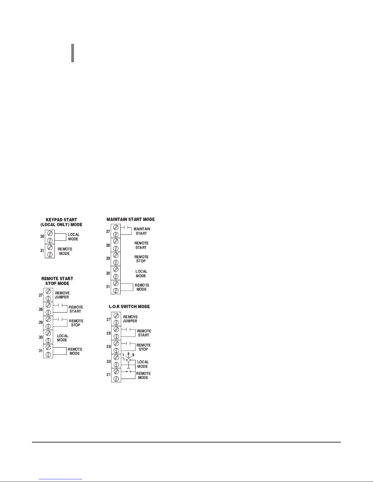
Start/Stop Configuration
The S1501 system can be configured for Local and/or Remote Start-Stop. Start-Stop is
configured via terminal block inputs TB30 (local), TB31 (Remote).
Keypad Start
Jumper installed in TB30. A valid sequence occurs when the ■ START/STOP key is pressed.
Likewise, while running, a valid stop sequence occurs when the ■ START/STOP key is
pressed.
Section 50 00-02-0271
2018-10-23 - 22 -
NOTE: A valid stop occurs when the ■ START/STOP key is pressed
Regardless of the Start-Stop mode.
Local-Off-Remote (L-O-R) Switch
L-O-R switch installed across TB30 (Local) and TB31 (Remote). A valid sequence occurs
when the L-O-R switch is placed in the Local position and the Start-Stop key is pressed OR the
L-O-R is placed in the Remote position, and the Remote Start signal is seen. A valid Stop
occurs when the L-O-R switch is placed in the OFF position, OR of in the Remote position and
a Remote Stop is seen.
Remote Start-Stop
Jumper installed in TB31. A valid sequence occurs when a Remote Start signal is seen.
Likewise, a valid stop occurs when the Remote Stop signal is seen.
Maintain Start
Jumper installed in TB31. A valid sequence occurs when the Maintain Start signal is seen.
Likewise, a valid stop occurs when the Maintain Start signal is lost.
Typical Start/Stop Wiring
Modbus Start/Stop and Reset
The S1501 system can be started and stopped remotely through the
Modbus communications port (RS232/RS485 serial port). Writing a “1”
to the start/stop register (40010) will initiate a start. Writing a “Ø” to the
start /stop register will initiate a stop. Writing “Ø” to the shutdown status
register (40004) will cause a reset.
Section 50 00-02-0271
2018-10-23 - 23 -

Address
Access
Description
40001
Read
RPM
40002
Read
ETM (Elapsed Run Time Meter) Hundred Hours ( 0 – 999)
40003
Read
Class B1 Timer Accumulator Seconds
40004
Read/
Write
Shutdown Status Enumeration/Remote Modbus Reset (0=OK, or terminal block number of
Shutdown event...writable to 0 for Modbus Reset)
System Internal shutdowns:
68 = Engine Overspeed (engine applications)
70 = Engine Underspeed (engine applications)
72 = Overcrank (engine applications)
74 = Permissive Failure
76 = Motor Starter Failure (motor applications)
78 = Local Stop (by keypad)
80 = Unexpected Engine Start (engine applications)
86 = Loss of Tach Signal (engine applications)
88 = Loss of Run Signal (motor applications)
96 = Engine Failure To Crank (engine applications)
40005
Read
Relay Output Status (bitmapped Bit 0=K1 ... Bit 1=K2, etc)
40006
Read
Inputs TB01-16 Status (bitmapped Bit 0=TB1 ... Bit 1=TB2, etc)
40007
Read
Inputs TB17-32 Status (bitmapped Bit 0=TB17 ... Bit 1=TB18, etc)
40008
Read
Inputs TB33-48 Status (bitmapped Bit 0=TB33 ... Bit 1=TB34, etc)
40009
Read
Inputs TB49-64 Status (bitmapped Bit 0=TB49 ... Bit 1=TB50, etc)
40010
Read/
Write
Start/Stop Register (writable for remote commands if Remote Mode on TB29 is closed and
remote maintained start digital input TB27 not used. It is active for a write of "0" at all
times to allow remote stopping, until a start signal is received again)
40011
Read/
Write
40011 = Load/Unload Register (writable for resetting the Load relay after the LOAD relay
has been energized by the program, and setting it again if it has been
reset through Modbus. This resets and restarts the Process delay, at the same time as the
Load relay is reset and set)
40012
Read
ETM (Elapsed Run Time Meter) Thousand Hours ( 0 – 99 )
40013
Read
State Bitmap
Bit 0 = “WAITING ON START”
Bit 1 = “PERMISSIVE”
Bit 2 = “PRELUBE”
Bit 3 = “CRANK PERMISSIVE”
Bit 4 = “PURGE”
Bit 5 = “FUEL DELAY”
Bit 6 = “CRANK”
Bit 7 = “REST”
Bit 8 = “RUN DELAY”
Bit 9 = “LOAD DELAY (WARMUP)”
Bit 10 = “LOADED”
Bit 11 = “UNLOADED”
Bit 12 = “IDLE (COOLDOWN)”
Bit 13 = “IGN GND DELAY”
Bit 14 = “POSTLUBE“
Bit 15 = “SHUTDOWN”
40014
Read
Alarm Status Enumeration (0=OK, or terminal block number of last alarm event)
Modbus Integer Holding Registers
Section 50 00-02-0271
2018-10-23 - 24 -

Troubleshooting
WARNING: Do NOT open power supply until operations have been
shut down and area has been rendered non-hazardous. Do NOT run
sensor wires in conduit with any other wire. Do NOT apply voltage
to any annunciator input terminals. Do NOT bundle sensor wires
with any other wiring. Make sure the voltage and current
requirements are within the S1501 system ratings.
Before going through the checklist below, refer to the connections and operation procedures.
Also check your system wiring schematic.
If any problems persist after you have made these checks, consult your nearest Murphy
facility.
Symptom: No display
Check that the Power & Control cable is firmly connected to the back of the S1501.
Check for damaged or broken wire.
Check for power failure or power input shutdown.
Check the 200 mA fuse within the S1501 power supply and replace if necessary.
NOTE: If after all of the above has been done, and there is still no display,
return the S1501 to Murphy for repair or replacement.
Symptom: Engine fails to start (Sensor switch fault display cannot be
cleared.)
Check that the Power & Control cable is firmly connected to the back of the S1501.
Check for damaged or broken wire.
Check that the sensor input cable connector (ribbon cable) is properly connected to
the back of the S1501.
Verify that the LED lights (within the power supply box) are lit indicating relays are
functioning.
Check that the wire leads on the terminal block under the Safety Barrier cover are
connected and tight. (See drawing at right.)
Measure the voltage between terminals 1 and 2 on the terminal block under the
Safety Barrier cover (voltage should read between 5 - 6 VDC). Do this with the
S1501 connected to the power supply, and with it disconnected. There should not be
more than a 0.5 V difference between the readings with the S1501 connected and
not connected.
Section 50 00-02-0271
2018-10-23 - 25 -

Check sensor wires with an ohmmeter and meg or high potential test only with wires
disconnected from sensor terminal block.
NOTE: If shutdowns still result, contact your nearest Murphy
representative/dealer.
Section 50 00-02-0271
2018-10-23 - 26 -

Power Consumption
120 VAC (7.5 VA)
12 VDC (3.5 watts)
24 VDC (3.5 watts)
Sensor Inputs
32 or 64 N.O. and/or N.C. inputs such as Murphy Swichgage®
instruments.
Field selectable as a Class A, B1, B2, C, P or ESD for shutdown,
alarm, or control function.
NOTE: Sensor inputs 27 through 32 reserved for control
functions.
Outputs
7-SPDT relay outputs, 5 A, 1/16 HP,
125/250 VAC/ 1 A, 30 VDC
NOTE: For hazardous areas an approved isolation barrier must
be used between sensor switch and input terminals if the sensor
output comes from any energy storing device such as a relay or
transistor.
Adjustable Time Delays
Permissive
Prelube
Purge
Fuel
Crank
Run
Class B1 Lockout
Class B2 Lockout
Process Lockout
Idle/Cooldown
Ignition Ground
Postlube
Cooler
Sensor Inputs Terminal Block
Rail mount DIN type; 32 terminals, screw type
Opto-Isolated Tach/Run Input
Magnetic pickup, 4.5 to 120 Vrms, 0-10 kHz. CD ignition,
positive or negative ground, 100 to 300 VDC, 3-666 Hz.
12 to 125 VDC or 120 Vrms, 50/60 Hz may be used for
run signals.
Operating Temperatures: 32 to 122°F (0 to
50°C)
Storage Temperatures: -4 to 158°F (-20 to
70°C)
Case : ABS plastic, 1/4 DIN (90 x 90 mm)
Communications
Factory configured for RS232; field-selectable for
RS485.
Alphanumeric Display
2 lines, each line with 16 characters (32 characters total)
Power Supply Enclosure
Explosion-proof, Class I, Division 1. Intrinsically safe
barrier built into the power supply, 120 VAC with 7 form
“C” relay outputs for the following functions (with
standard S1501):
Lube
Crank
Ignition/Motor
Fuel/Cooler
Load
Alarm
Shutdown
Specifications
Section 50 00-02-0271
2018-10-23 - 27 -

S1501H-32-2
S1501H-64-2
S1501CH-32-2
S1501CH-64-2
S1500TB32
S1500CA36
S1501PS-120
Accessories:
S1501PCA72
S1501PS-120-E
S1501PS-120-LC
Head with RS232/RS485 port for 32 sensors
Head with RS232/RS485 port for 64 sensors
Head w/custom* program, RS232/RS485 port, 32 sensors
Head w/custom* program, RS232/RS485 port, 64 sensors
Terminal Block only**
Ribbon Cable Assembly**
120 VAC, 12 or 24 VDC Power Supply
Power and Control Cable Assembly, 72 in. (1.8 m) long
Power Supply with 90° Conduit Elbow fitting
Power Supply less case
Replacement Parts and Accessories
To order the S1501 system specify the model number for each individual component and accessory:
Approximate Shipping Weights / Dimensions
S1501 complete system:
28 lb. (12.7 kg) / 20x14x12.5 in. (508x356x218mm)
S1501H-32-2; S1501H-64-2; S1501CH-32-2; S1501CH-64-2:
2 lb. (0.907 kg) / 6x6x6 in. (152x152x152mm)
S1500TB32:
2 lb. (0.907 kg) / 12x7x4 in. (305x178x102mm)
S1500CA36; S1501PCA72:
2 lb. (0.907 kg) / 6x6x6 in. (152x152x152mm)
S1501PS-120-LC:
3 lb. (1.36 kg) / 12x7x4 in. (305x178x102mm)
S1501PS-120 and S1501PS-120-E:
22 lb. (9.98 kg) / 17x10x9.75 in. (431x254x248mm)
Section 50 00-02-0271
2018-10-23 - 28 -

.
Section 50 00-02-0271
2018-10-23 - 29 -

 Loading...