

Page 1
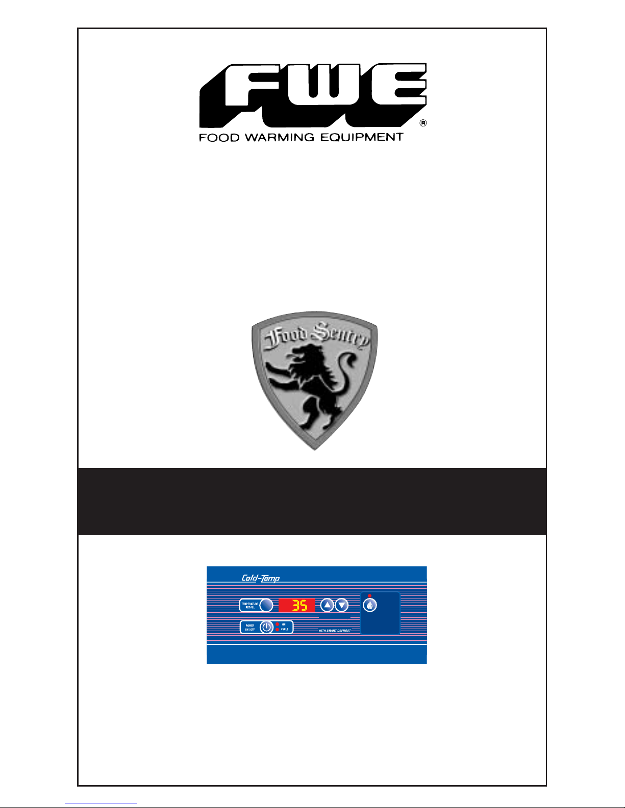
R SERIES URS SERIES SR SERIES
RBQ-96 F SERIES UFS SERIES
REFRIGERATORS
&
FREEZERS
OPERATING
INSTRUCTIONS
DEFROST
CYCLE
Press for
"ON DEMAND"
or Defrost
Override
TEMP SETTING
TM
Page 2
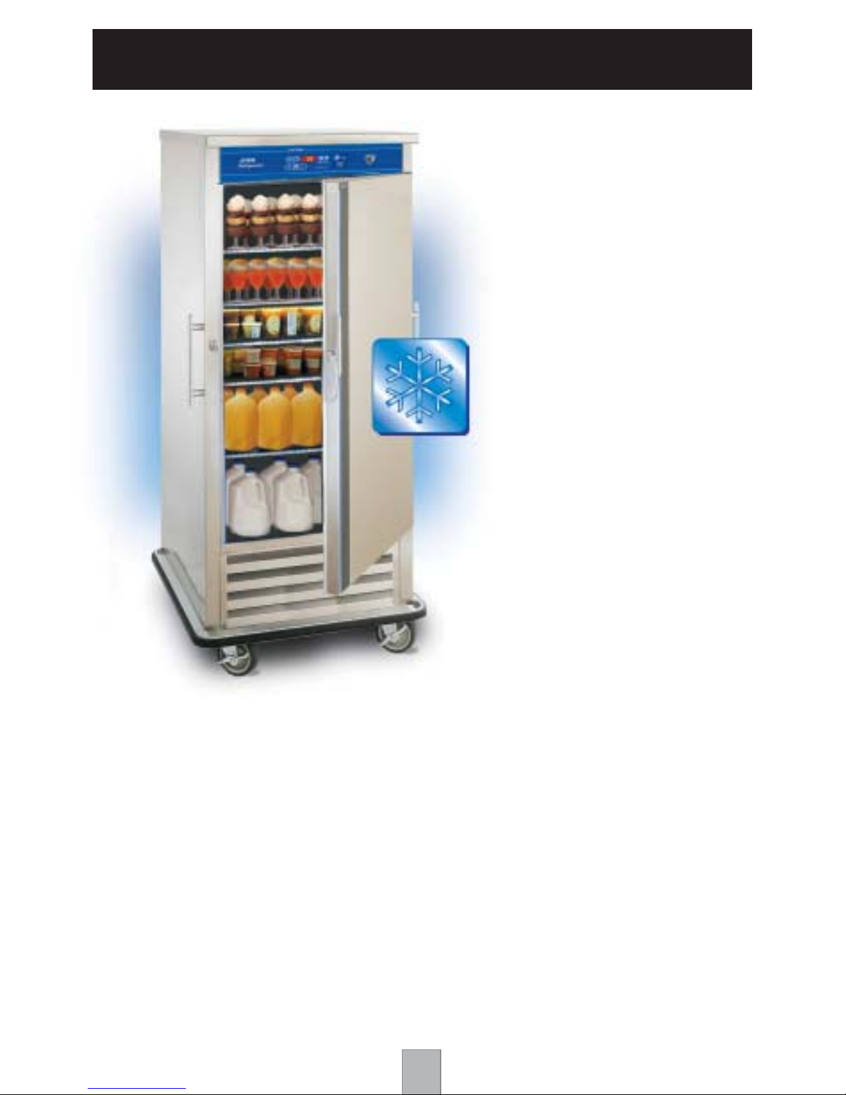
FWE COLD-SERVE CABINETS
CONGRATULATIONS...
...and thank you for purchasing an FWE COLD-SERVE Refrigerator or
Freezer Cabinet.Your unit has been designed and manufactured under
rigid controls to assure you the most efficient service. It is a full time
unit, and may be used continuously.
Please take a moment to read through this booklet of important
information pertaining to your cabinet. By following a routine of
proper use and care described on the following pages, your cabinet
will last for many years.
IMPORTANT: Your Manufacturer Registration Card must be
returned within 30 days after initial delivery to put warranty into effect.
2
FWE’ s “COLD-TEMP”
Food Sentry System
keeps food cold or
fresh frozen —
without dehydration!
Page 3
FWE MOBILE REFRIGERATORS AND FREEZERS
FOOD SENTRY CONTROLS
3
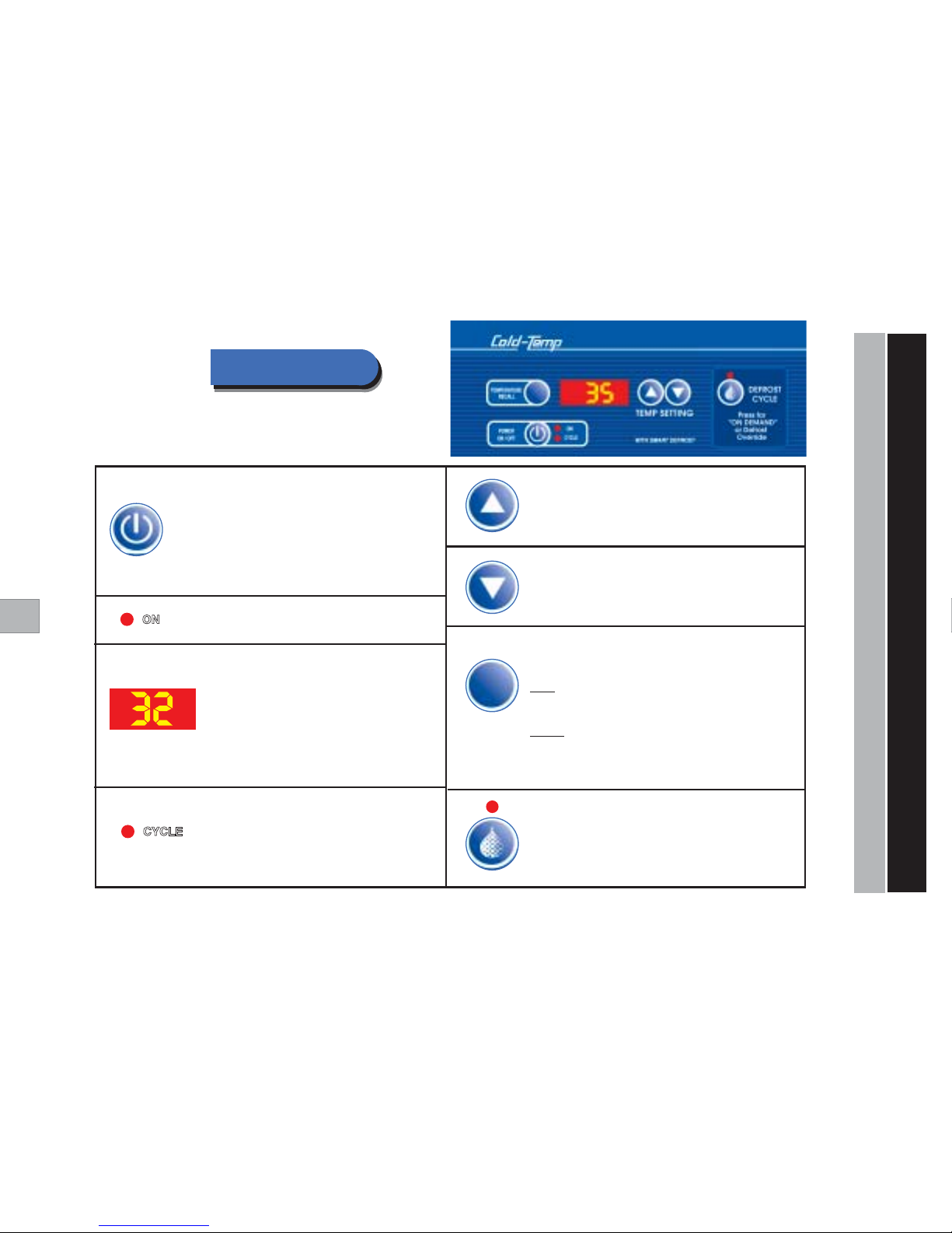
POWER ON / OFF - Turns cabinet ON and OFF.
Also Changes Display to °Celsius or °Fahrenheit Scale:
You may change the Digital thermometer scale to either
°C or °F as follows:While unit is OFF, press and hold the
“ON/OFF” key
for five (5) seconds.The display will then
switch from
“dgF” to “dgC”
. Repeat to change scale again.
TEMPERATURE RECALL
Press to display either
“Actual Internal Cabinet”
actual temperature, or desired
“Set Point”
temperature.
Actual:
The factory default setting shows the actual internal cabinet temperature
and acts as a digital thermometer. A momentary touch of the
“Temp Recall”
key
will recall the original dial setting.The display will then automatically return to the
actual internal temperature.
Set Point:
To have temperature read-out display the
“Set Point”
temperature,
press and hold the
“Temp”
key for five (5) seconds.The fourth (4th) digit on the
display will flash either
“S”
(Set), or
“A”
(Actual) to indicate which mode is active.
To switch back again, repeat this step holding the
“Recall Temp Set”
key for five (5) seconds.
Power Indicator Light -
Indicates that the power is on.
Cycling Indicator Light -
When light is
“ON”
, this indicates that the
cabinet is cooling down to desired temperature.
When cooling elements are activated, light will
come
“ON”
until cabinet has reached desired
temperature, and go
“OFF”
when unit has
reached desired temperature.
TEMP SETTING - Lowering the Temperature
Press to lower the temperature of the cabinet.
TEMP SETTING - Raising the Temperature
Press to raise the temperature of the cabinet.
Activated red light indicates DEFROST is in progress.
DEFROST CYCLE - “ON DEMAND” DEFROST
Press to ACTIVATE DEFROST at any time.
Press to CANCEL DEFROST in progress (Defrost Override).
Q
Q
Q
UICK-START
GUIDE
“COLD-TEMP” FOOD SENTRY SYSTEM
Temp Display - Digital temperature display shows
the temperature of the cabinet.
“dgF” = Degrees
Fahrenheit
“dgC” = Degrees
Celsius
You may change the Digital thermometer scale to
either °C or °F as follows:While unit is OFF, press
and hold the
“ON/OFF” key
for five (5) seconds.
The display will then switch from
“dgF” to “dgC”
.
Repeat to change scale again.
Page 4

FWE standard models operate on 110/120 volt,
60 Hz, 1 ph, A.C. (unless ordered otherwise), and are equipped
with a three prong grounding cord plug for your protection against
possible shock hazards. Be sure to plug only into a properly
grounded three prong wall receptacle. If you have any questions
with regard to adequate wiring or grounding in your building,
a qualified electrician should be contacted before using your
cabinet. The amperage of your cabinet is stamped on the
name plate attached to the unit.
DO NOT, UNDER ANY CIRCUMSTANCES, CUT OR REMOVE
THE GROUNDING PRONG FROM THE CORD PLUG.
WARNING: ONLY A QUALIFIED ELECTRICIAN SHOULD
ATTEMPT TO REPAIR OR REPLACE ELECTRICAL
COMPONENTS OR WIRING.
BE SURE THAT MODEL IS UNPLUGGED FROM ELECTRICAL
SOURCE BEFORE REMOVING CONTROL PANEL.
FWE MOBILE REFRIGERATORS AND FREEZERS
SERIAL AND MODEL NUMBER
INSTALLATION
UNPACKING
ELECTRICAL REQUIREMENTS AND GROUNDING
These numbers are found on the nameplate (serial tag) affixed
to the unit.The serial tag is located by the electrical cord.
Please record them on the back of this booklet. When ordering
parts and/or ser vice, you will need to provide this information.
The voltage and amperage of the unit are also stamped on the
serial tag.
After uncrating your cabinet, remove all tape and padding
which held all doors, shelves, racks, cord, etc., in place
during shipment.
4
Page 5

1) PLUG CABINET INTO A PROPERLY GROUNDED POWER
RECEPTACLE. Press ON/OFF Icon to “ON” position. The red
indicating light will come on and remain on until power button
is pressed to “OFF”, or the unit is unplugged.
2) CONDENSER CLEARANCE. Keep a minimum of 6'' clear all
around unit to allow condenser to vent war m air.
3) SELECT A TEMPERATURE SETTING.
Pre-Set at 35°F for REFRIGERATOR:
Temperature Range: 33°F to 41°F (1°C to 5°C)
Pre-Set at 15°F for FREEZER:
Temperature Range: 5°F to 32°F (-15°C to 0°C)
Press ▲ to raise the temperature of the cabinet and scroll to
desired temperature. Press ▼ to lower the temperature of the
cabinet and scroll to desired temperature.
4) PRE-CONDITION CABINET FOR 30-60 MINUTES.
Your cabinet should be pre-cooled 30-60 minutes before loading
at your desired set temperature.
AVOID PUTTING HOT FOODS INTO A COLD CABINET!
5) LOADING THE CABINET - During the loading procedure, keep
the doors closed as much as possible. After loading is completed,
do not open doors again until you are ready to serve.
6) TRANSPORTING FOODS - Your cabinet is equipped with a
positive transportation latch to assure safety during transportation.
After loading the cabinet, keep it plugged in with the door closed
and wait 15 - 20 minutes before moving it, to allow it to reach
maximum holding temperature.Then wheel to ser ving area, and
plug the cabinet into an electrical outlet at the ser ving location
(if available), so that the compressor will re-activate and
automatically hold at the pre-selected temperature.
GENERAL OPERATING INSTRUCTIONS
OPERATING THE CABINET
5
Page 6

FOR BEST USE AND CARE
GENERAL OPERATING INSTRUCTIONS
Keep your cabinet clean by simply wiping the interior and
exterior, as needed, with a damp cloth or sponge and a mild
soapy solution. NEVER USE ABRASIVES, ACIDS, OR
STRONG CLEANERS. Do not flood or allow electrical
parts to become wet. The interior tray slide assemblies
and humidifier pans are removable for easy cleaning.
A stainless steel cleaner/polish is recommended for
the exterior to maintain a "like-new" appearance.
DO NOT USE WAX OR STRONG CLEANERS
ON DOOR GASKETS OR VINYL TRIM.
CLEANING
FOR BEST RESULTS - Your Cold-Ser ve cabinet should be
pre-cooled for 15 - 30 minutes before loading. The compressor
cycling light will go off when unit has reached the pre-set
temperature.
AVOID PUTTING HO
T FOODS INTO A COLD CABINET!
LO ADING THE CABINET - During the loading procedure,
keep the doors closed as much as possible. After loading is
completed, do not open doors again until you are ready to
serve.
TRANSPORTING COLD FOODS - Your cabinet is equipped
with a positive transportation latch to assure safety during
transportation. Before moving the cabinet, keep it plugged in
and wait until the compressor cycling light goes off.This takes
only a short time. As soon as the cycling light goes off, unplug
the cabinet and wheel to serving area. Plug the cabinet into an
electrical outlet at the ser ving location (if available) so that the
compressor will re-activate and automatically hold at the
pre-selected temperature.
6
Page 7
7
WARNING: RISK OF ELECTRICAL SHOCK.
DISCONNECT ELECTRICAL POWER SUPPLY
BEFORE CLEANING ANY PARTS OF THE UNIT
OR PRIOR TO ANY SERVICE.
The most important thing you can do to insure a long, reliable
service life for your FWE Refrigerator or Freezer is to
regularly
clean the condenser (compressor) coil.
The condensing unit
requires regularly scheduled cleaning to keep the finned
condenser clean of lint and dust accumulation.
Keeping the condenser clean allows the cabinet to operate
efficiently, use less energy, and achieve top performance values.
To clean the condenser, first disconnect electr ical power to the
cabinet and remove the front and/or rear louver assembly.To
remove this, remove the screws located on louver assembly.
Once the screws are removed, the panel can be removed allowing
full access to the front facing condenser. Vacuum any dirt, lint,
or dust from the finned condenser coil, the compressor and other
cooling system parts. If significant dir t is clogging the condenser
fins*, use brush or compressed air to blow this clear.
NOTE: Care should be taken not to bend any of the condenser
fins, as this will reduce performance and compressor life.
Replace louver assembly and screws which hold it in place.
CLEANING THE CONDENSER:
GENERAL OPERATING INSTRUCTIONS
CLEANING THE CONDENSER FOR BEST PERFORMANCE
Page 8
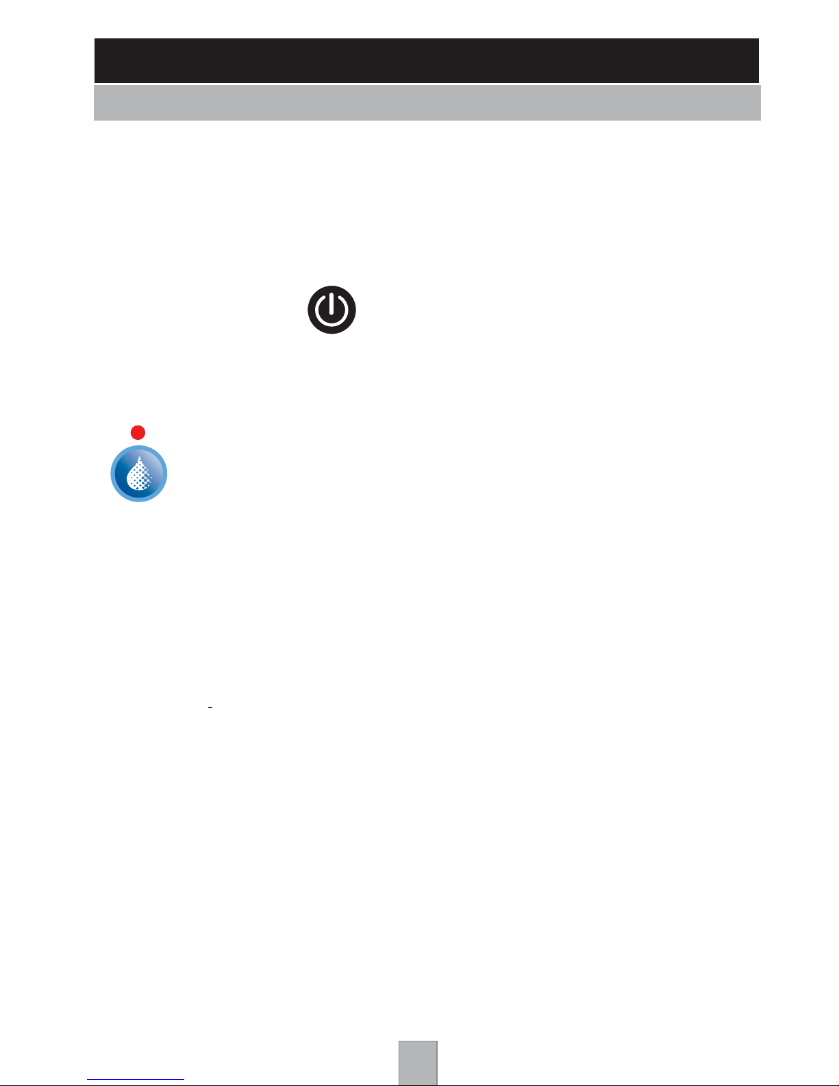
Activated red light above the defrost cycle button indicates DEFROST mode is in progress.
DEFROST CYCLE - “ON DEMAND” DEFROST
Press to ACTIVATE DEFROST at any time.
Press to CANCEL DEFROST in progress (Defrost Override).
It is possible that the unit will self-initiate a defrost if excessive ice is on coil. NOTE: If the coil is not defrosted,
temperatures will rise and reduced performance will be noticeable.If the unit is in a defrost cycle, it can be
cancelled by pushing the defrost button.This will force the unit out of the defrost cycle.The unit will await
30 to 60 seconds at the end of a defrost before the compressor and or the fans will return to normal operation,
achieving the best restart performance and cooling temperatures. In addition to a self-initiated defrost, the unit is
supplied with a forced “on demand” defrost cycle. It is located on the front control, and by depressing the switch,
the unit will be forced into a self-defrost (maximum of 20 minutes).During a defrost cycle, the indicator light will
illuminate above the switch and momentar ily disable the compressor, the coil and the fans. Defrost feature allows
proper defrosting of the accumulated condensation and ice build-up on the coil. As with the self-initiated defrost,
if the unit is in a defrost cycle, it can be cancelled by pressing the defrost button.Wait approximately 60 seconds
for defrost to end.
During the defrost cycle or the “Off Cycle” of the compressor, the evaporator coil will defrost.
The condensation from the evaporator coil flows from the top of the unit down a drain in the back to a condensate
pan.Vapor escapes through the back gr ill. The vapor can sometimes be visible and should be considered a
normal operating condition. Proper attention should be given to defrosting your unit. Every “event” or time the unit
is used with the door open, the coil will build-up ice, reducing the effectiveness of the overall operation of the unit.
If the temperature zone is too high and cabinet will not chill to desired temperature:
1) The evaporator coil needs defrosting. Press the “ON DEMAND DEFROST”button on the control panel.
Unit will defrost in approximately 20 minutes.Defrost indicator light will illuminate during defrost cycle.
The unit will automatically return to normal operation after a defrost cycle, having a transition time of 60 seconds.
Certain conditions may require 3 repeated sequential defrosts.
2) Dirt, lint, and/or dust are on the condenser (compressor) coil. To clean the condenser, first disconnect
electrical power to the cabinet and remove the screws on the front and/or rear louver assembly. Removed
louvered panel allowing full access to the front facing condenser.Vacuum any dirt, lint, and/or dust from the
finned condenser coil, the compressor and other cooling system parts. If significant dir t is clogging the condenser
fins, use brush or compressed air to blow this clear. NOTE: Care should be taken not to bend any of the
condenser fins, as this will reduce performance and compressor life. Replace louver assembly and
screws which hold it in place.
TROUBLE-SHOOTING CHART
Check this list first before you call for service...
PROBLEM REMEDY
Control panel will not light up. Cabinet not plugged into outlet or check fuse to power outlet.
Plug cabinet into properly grounded electrical outlet.
Press “ON” button.
Cabinet will not reach Opening door unnecessarily.
Keep door closed and latched shut after loading.
desired temperature. Set temperature to
Display to °Celsius or °Fahrenheit Scale:
You may change the Digital thermometer scale to either °C
or °F as follows:While unit is OFF, press and hold the
“ON/OFF” button
for five (5) seconds.The display will then
switch from
“dgF” to “dgC”
. Repeat to change scale again.
Display reads
“dgF”
Temperature is set to
°Fahrenheit Scale
Display reads
“dgC”
Temperature is set to
°Celsius Scale
8
Page 9

9
PARTS LIST
FWE PARTS DEPARTMENT: 815 459 7500
DESCRIPTION PART NUMBER
BUMPER INSERT, BLACK VINYL BMPR INSERT
DOOR HINGE, EDGEMOUNT HNG-217
DOOR LATCH, EDGEMOUNT, NON-LOCKING LTH-DR
DOOR LATCH, EDGEMOUNT, LOCKING W/KEYS LTH-DR-MAG-MECH
DOOR LATCH, PADDLE LTH PDL-STD 125
DOOR GASKET (RBQ) GSKT MAG2049
DOOR GASKET (URS-14, UFS-14) GSKT MAG2436
DOOR GASKET (R-30,SR-30,R-60,SR-60,F-30,SF-30,F-60, SF-60) G SKT MAG2248
DOOR GASKET (URS-10,URS-20,UFS-10,UFS-20) GSKT MAG2648
PUSH HANDLE - 1" X 12" HDL 12.5 AL
PUSH HANDLE - 1" X 21.5" HDL 215 AL
SPACER FOR PUSH HANDLE SPCR125X.330
6" POLY CASTER, RIGID CSTR-6-R-2
6" POLY CASTER, SWIVEL W/BRAKE CSTR-6-SB-2
POWER CORD, 115 VOLT, 10' CRDSET 10/115
POWER CORD, 200 VOLT, 10' CRDSET 10/220
TRAY SLIDES, PR (R-30,R-60,F-30,F-60) SLD TS245
TRAY SLIDES, PR (URS-10,URS-14,URS-20,UFS-10,UFS-14,UFS-20) SLD UHS245
WIRE SHELF (SR-30,SR-60,SF-30,SF-60) SHLF SR30
EVAPORATOR MOTOR EVAP TL12-16AG MOTOR
EVAPORATOR FAN BLADE
(R-30,SR-30,F-30,SF-30,URS-10,UFS-10,RBQ)
EV AP TL12-16A G FAN BLD
EVAPORATOR FAN BLADE (
R-60,SR-60,F-60,SF-60,URS-14,UFS-14,URS-20,UFS-20)
EVAP KMK FAN BLD
EVAPORATOR MOTOR MOUNT EVAP TL12-16AG MOUNT
GRILL FAN GUARD / EVAPORATOR
(R-30,SR-30,F-30,SF-30,URS-10,UFS-10,RBQ)
EV AP TL12-16A G FAN GRD
GRILL FAN GUARD / EVAPORATOR EVAP KMK FAN GRD
(R-60,SR-60,F-60,SF-60,URS-14,UFS-14,URS-20,UFS-20)
DE-ICE CONTROL SWITCH
(FOR UNITS WITH ELECTRICAL DEFROST)
T-STAT-DEFROST-SL55
DEFROST HI-LIMIT SWITCH
(FOR UNITS WITH ELECTRICAL DEFROST)
SNAP DISC
CONTROLLER CNTRL-REFRIG-6MOD
TEMPERATURE PROBE THERMISTOR-PROBE-REF-37
CATCH ALL FILTER DRIER FLTR-DRY-BRZ
CONTACTOR RELAY CONTACT-2 POLE-120V-40AMP
EVAPORATOR ASSEMBLY W/ELECTRICAL DEFROST EVAP TL12AG
(R-30,SR-30,URS-10,F-30,SF-30,UFS-10)
EVAPORATOR ASSEMBLY W/ELECTRICAL DEFROST (RBQ) EVAP TL16AG
EVAPORATOR ASSEMBLY W/ELECTRICAL DEFROST EVAP KMK23AG
(R-60,SR-60,F-60,SF-60,URS-14,UFS-14,URS-20,UFS-20)
CONDENSER / COMPRESSOR ASSEMBLY (FOR 134A SYSTEM) COND-UNIT-R-134
COMPRESSOR ONLY 134A (FOR 134A SYSTEM) COMP-R-134
THERMAL EXPANSION VALVE 1/2 TON (FOR 134A SYSTEM) VLV-EXP-R-BRZ
COMPRESSOR RELAY (FOR 134A SYSTEM) COND-UNIT-R-134-RELAY
COMPRESSOR OVERLOAD (FOR 134A SYSTEM) COND-UNIT-R-134-OVERLOAD
COMPRESSOR START CAPACITOR (FOR 134A SYSTEM) COND-UNIT-R-134-ST-CAPAC
CONDENSER / COMPRESSOR ASSEMBLY (FOR 404A SYSTEM) COND-UNIT-F-404
COMPRESSOR ONLY (FOR 404A SYSTEM) COMP-F-404
THERMAL EXPANSION VALVE 1/2 TON (FOR 404A SYSTEM) VLV-EXP-R3-BRZ
COMPRESSOR RELAY (FOR 404A SYSTEM) COND-UNIT-F-404-RELAY
COMPRESSOR OVERLOAD (FOR 404A SYSTEM) COND-UNIT-F-404-OVERLOAD
COMPRESSOR START CAPACITOR (FOR 404A SYSTEM) COND-UNIT-F-404-ST-CAPAC
DEFROST ELEMENT (FOR EVAP TL12AG) EVAP TL12AG HEATER
DEFROST ELEMENT (FOR EVAP TL16AG) EVAP TL16AG HEATER
DEFROST ELEMENT (FOR EVAP KMK23AG) EL500-115V-SEALED END
Page 10
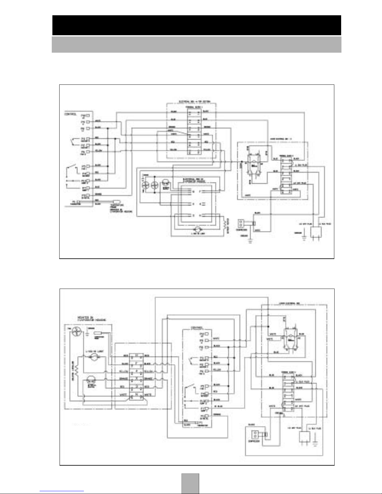
FWE MOBILE REFRIGERATORS AND FREEZERS
WIRING DIAGRAMS
10
115v Models
URS-10, R-30, SR-30, RBQ-96, UFS-10, F-30, SF-30
115v Models
R-60, SR-60, URS-20, URS-14, F-60, SF-60, UFS-20, UFS-14
Page 11

FWE REFRIGERATORS AND FREEZERS
LIMITED TWO YEAR WARRANTY
11
FWE / Food Warming Equipment Company, Inc. (Seller) warrants to the original purchaser,
subject to the exceptions and conditions below, that FWE manufactured equipment shall be
free from defects in material or factory workmanship, under ordinary use for the purpose for
which it is designed.The effective warranty period is as follows:
PARTS: Seller will furnish without charge to the original purchaser, FOB Sellers’ factory,
replacement parts for repairs to all new standard catalog products and factory custom /
modified units, which in Seller’s sole judgement, prove defective in materials or workmanship
under normal and proper use with the reser ved right to request the return of any part claimed
to be defective, prior to issuing replacement part or author izing warranty service, for a period
of two (2) years from date of original shipment from Seller’s plant,
except for equipment used
in a Correctional Environment / Facilities, which is warranted for a per iod of one (1) year
from date of original shipment from Seller’s plant.
LABOR: Seller’s labor warranty shall be performed by a Seller-approved Service Agency who
must contact Seller to obtain a Warranty Service Authorization (WSA) number prior to
performing any repairs. If service is required during overtime per iods, the difference between
overtime and standard labor rates shall be paid by the purchaser.Seller does not assume any
responsibility for any charges not expressly author ized, incidental to the repair or replacement
of equipment covered by this warranty, nor charges exceeding, in Sellers sole judgement,
normal and customar y amounts. Only approved travel charges will be allowed. Seller’s labor
warranty shall be from the date of original shipment date from Seller’s plant for a period of one
(1) year,
except for equipment used in a Correctional Environment / Facilities which is
warranted for a period of six (6) months.
This warranty is for normal usage and does not apply to any product or parts thereof that have
been misused, altered, or where Seller’s operating instructions or specific voltage is not
observed; nor shall this warranty apply to defective products or par ts resulting from accident
following date of original shipment, nor e xtend to or co v er remo v al, installation, reinstallation or
calibration, or service calls or cost of repairs under taken by a customer. This warranty is also
subject to the following:
1.] Customer returning the warranty registration card, accompanying Sellers original
shipment, to Seller within thirty (30) days of receipt;
2.] Giving immediate notice of any allegedly defective part or product to Seller; and
3.] Customer, at Sellers request, returning said defective parts or product to Seller.
This is the sole warranty applicable to the merchandise .It is expressly understood that Seller’s
liability hereunder is limited to the repair or replacement, at Seller’s option, of products or parts,
defectiv e materials or workmanship as provided abov e .Seller’ s judgement as to the cause and
nature of any defect will be final.Seller shall in no case be responsible for special or consequential damages or any other obligation or liability with respect to products sold by Seller.
This warranty, as stated above , applies to equipment installed in the Continental United States.
FWE equipment installed outside the Continental United States shall carry parts coverage
only. All labor costs are approved on a discretionary basis, based on like repairs in the
Continental U.S.This warranty shall stand in whole or in part as allowed by law. Any exclusion
of a part of this warranty, as may be allowed by law, shall not void balance of warranty.
This is a limited warranty pursuant to the Consumer Product Warranties Act, 15 U.S. Code. section 2303.
© 2004 Food Warming Equipment Co., Inc.
Page 12
FWE MOBILE REFRIGERATORS AND FREEZERS
SERVICE RECORD
Model Number ______________________
Serial Number ______________________
Date of Purchase ____________________
Notes:
___________________________________________________
___________________________________________________
___________________________________________________
___________________________________________________
___________________________________________________
___________________________________________________
___________________________________________________
___________________________________________________
___________________________________________________
___________________________________________________
___________________________________________________
___________________________________________________
___________________________________________________
___________________________________________________
Manual_Cold-Temp © 2008 Food War ming Equipment Co., Inc. Printed in USA
FWE Parts Department:
815 459 7500
FAX:
815 459 7989
WE OFFER SALES AND SERVICE WORLDWIDE
Food Warming Equipment Company, Inc.
P.O. Box 1001
Crystal Lake, IL 60039-1001
Manufacturing Facilities:
7900 S. Route 31
Crystal Lake, IL 60014
Errors subject to correction. All specifications
subject to change without notice.
© 08 Food Warming Equipment Company. Inc.
 Loading...