

F.W. Bell 9900 Series Operation & Maintenance Manual

Artisan Technology Group is your source for quality
new and certied-used/pre-owned equipment
• FAST SHIPPING AND
DELIVERY
• TENS OF THOUSANDS OF
IN-STOCK ITEMS
• EQUIPMENT DEMOS
• HUNDREDS OF
MANUFACTURERS
SUPPORTED
• LEASING/MONTHLY
RENTALS
• ITAR CERTIFIED
SECURE ASSET SOLUTIONS
SERVICE CENTER REPAIRS
Experienced engineers and technicians on staff
at our full-service, in-house repair center
Instra
Remotely inspect equipment before purchasing with
our interactive website at www.instraview.com
Contact us: (888) 88-SOURCE | sales@artisantg.com | www.artisantg.com
SM
REMOTE INSPECTION
View
WE BUY USED EQUIPMENT
Sell your excess, underutilized, and idle used equipment
We also offer credit for buy-backs and trade-ins
www.artisantg.com/WeBuyEquipment
LOOKING FOR MORE INFORMATION?
Visit us on the web at www.artisantg.com for more
information on price quotations, drivers, technical
specications, manuals, and documentation
9000
SERIES
GAUSSMETERS
SK NFg 9:!..'0
GAL'S:ME IEH
O
a
0
,12111b4U411,4 /CI !V q 1 I I I' 4,4
*AA
SERIES
9900 GAUSSMETER
900
SERIES
9900
9000
SERIES
GAUSSMETERS
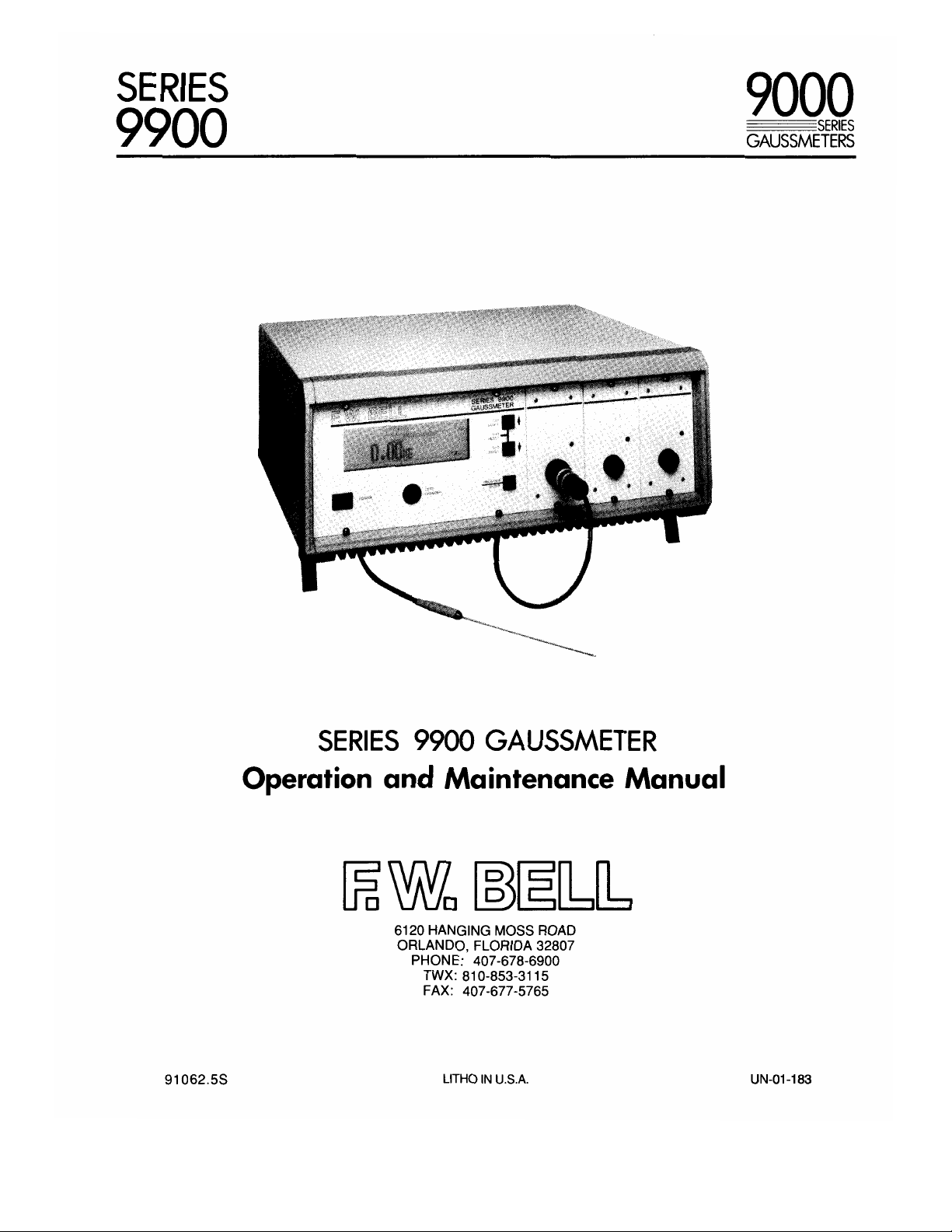
SERIES 9900 GAUSSMETER
Operation and Maintenance Manual
E
6120 HANGING MOSS ROAD
ORLANDO, FLORIDA 32807
PHONE: 407-678-6900
TWX: 810-853-3115
FAX : 407-677-5765
91062.5S
LITHO IN U.S.A. UN-01-183
SERIES
9900
9000
SERIES
GAUSSMETERS
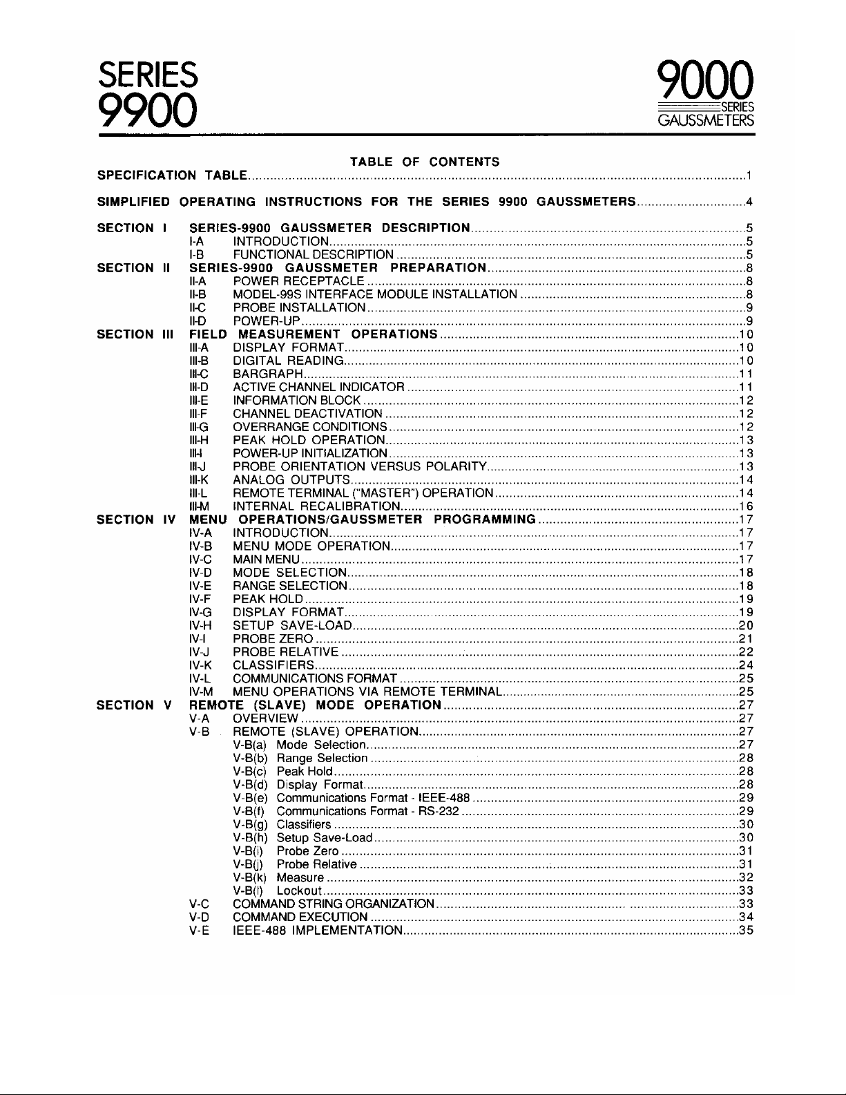
SPECIFICATION
SIMPLIFIED OPERATING
SECTION I
SECTION II
SECTION III FIELD
SECTION IV MENU
SECTION V REMOTE (SLAVE) MODE OPERATION 27
TABLE
INSTRUCTIONS FOR THE SERIES 9900 GAUSSMETERS
SERIES-9900 GAUSSMETER DESCRIPTION
-A INTRODUCTION
-B FUNCTIONAL DESCRIPTION
SERIES-9900 GAUSSMETER PREPARATION
V-A OVERVIEW 27
V-B
V-C
V-D
V-E
POWER RECEPTACLE
I-A
MODEL-99S INTERFACE MODULE INSTALLATION
I-B
I-C PROBE INSTALLATION 9
I-D POWER-UP
II-A DISPLAY FORMAT
II-B DIGITAL READING
II-C BARGRAPH
II-D ACTIVE CHANNEL INDICATOR 1 1
II-E INFORMATION BLOCK 12
II-F
I-G
II-H PEAK HOLD OPERATION
I-I POWER-UP INITIALIZATION
Il-J PROBE ORIENTATION VERSUS POLARITY
II-K ANALOG OUTPUTS
II-L REMOTE TERMINAL ("MASTER") OPERATION
I-M INTERNAL RECALIBRATION
V-A INTRODUCTION
V-B
V-C
V-D
V-E RANGE SELECTION
V-F PEAK HOLD
V-G DISPLAY FORMAT
V-H SETUP SAVE-LOAD 20
V-I PROBE ZERO 21
V-J
V-K CLASSIFIERS
V-L COMMUNICATIONS FORMAT
V-M MENU OPERATIONS VIA REMOTE TERMINAL
MEASUREMENT OPERATIONS 10
CHANNEL DEACTIVATION 12
OVERRANGE CONDITIONS 12
OPERATIONS/GAUSSMETER PROGRAMMING
MENU MODE OPERATION
MAIN MENU 17
MODE SELECTION 18
PROBE RELATIVE 22
REMOTE (SLAVE) OPERATION 27
V-B (a) Mode Selection
V-B(b) Range Selection
V-B (c) Peak Hold 28
V-B(d) Display Format 28
V-B(e) Communications Format - IEEE-488 29
V-B(f) Communications Format - RS-232
V-B(g) Classifiers
V-B(h) Setup Save-Load
V-B(i) Probe Zero
V-B(j) Probe Relative
V-B (k) Measure
V-B (I) Lockout
COMMAND STRING ORGANIZATION
COMMAND EXECUTION 34
IEEE-488 IMPLEMENTATION
TABLE OF CONTENTS
10
10
11
13
13
13
14
14
16
17
17
17
18
19
19
24
25
25
27
28
29
30
30
31
31
32
33
33
35
1
4
5
5
5
8
8
8
9
SERIES
9900
9000
SERIES
GAUSSMETERS
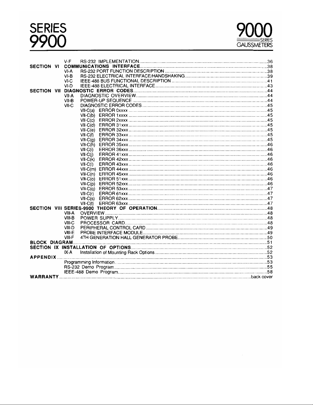
SECTION VI COMMUNICATIONS INTERFACE38
SECTION VII DIAGNOSTIC ERROR CODES44
SECTION VIII SERIES-9900 THEORY OF OPERATION48
BLOCK DIAGRAM51
SECTION IX INSTALLATION OF OPTIONS52
APPENDIX53
WAR RANTYback cover
V-F RS-232 IMPLEMENTATION36
VI-A RS-232 PORT FUNCTION DESCRIPTION38
VI-B RS-232 ELECTRICAL INTERFACE/HANDSHAKING39
VI-C IEEE-488 BUS FUNCTIONAL DESCRIPTION41
VI-D IEEE-488 ELECTRICAL INTERFACE43
VII-A DIAGNOSTIC OVERVIEW44
VII-B POWER-UP SEQUENCE44
VII-C DIAGNOSTIC ERROR CODES45
VII-C(a) ERROR 0xxxx45
VII-C(b) ERROR 1 xxxx45
VII-C(c) ERROR 2xxxx45
VII-C(d) ERROR 31xxx45
VII-C(e) ERROR 32xxx45
VII-C(f) ERROR 33xxx45
VII-C(g) ERROR 34xxx45
VII-C(h) ERROR 35xxx46
VII-C(i) ERROR 36xxx46
VII-C(j) ERROR 41xxx46
VII-C(k) ERROR 42xxx46
VII-C(I) ERROR 43xxx46
VII-C(m) ERROR 44xxx46
VII-C(n) ERROR 45xxx46
VII-C(o) ERROR 51xxx46
VII-C(p) ERROR 52xxx46
VII-C(q) ERROR 53xxx47
VII-C(r) ERROR 61xxx47
VII-C(s) ERROR 62xxx47
VII-C(t) ERROR 63xxx47
VIII-A OVERVIEW48
VIII-B POWER SUPPLY48
VIII-C PROCESSOR CARD48
VIII-D PERIPHERAL CONTROL CARD49
VIII-E PROBE INTERFACE MODULE49
VIII-F 4TH GENERATION HALL GENERATOR PROBE50
IX-A Installation of Mounting Rack Options52
Programming Information53
RS-232 Demo Program55
IEEE-488 Demo Program58
SERIES
9900
RANGES/RESOLUTION 01X PROBE
9000
SERIES
GAUSSMETERS
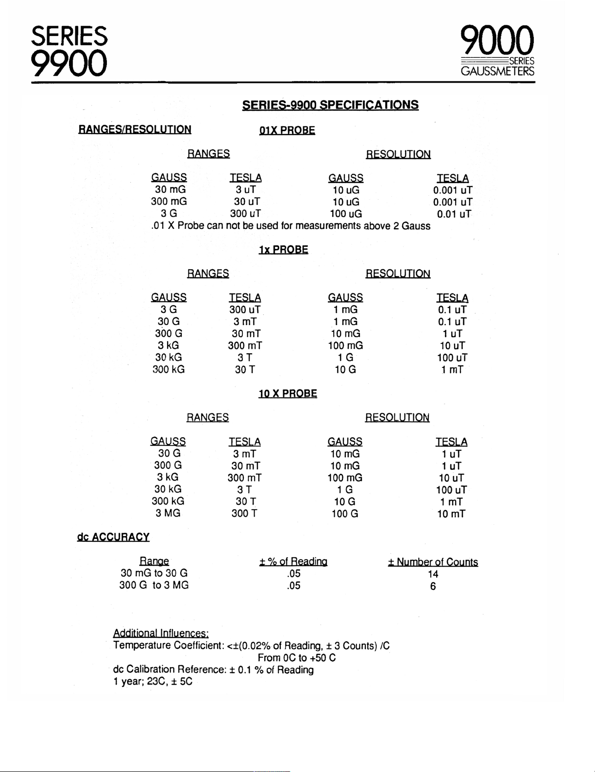
SERIES-9900 SPECIFICATIONS
RANGES RESOLUTION
GAUSS TESLA GAUSS TESLA
30 mG 3 uT 10 uG 0.001 uT
300 mG 30 uT 10 uG 0.001 uT
3 G 300 uT 100 uG 0.01 uT
.01 X Probe can not be used for measurements above 2 Gauss
lx PROBE
RANGES RESOLUTION
GAUSS TESLA GAUSS TESLA
3 G 300 uT 1 mG 0.1 uT
30 G 3 mT 1 mG 0.1 uT
300 G 30 mT 10 mG 1 uT
3 kG 300 mT 100 mG 10 uT
30 kG 3 T 1 G 100 uT
300 kG 30 T 10 G 1 mT
dc ACCURACY
Ran t % of Reading t Number of Counts
30 mG to 30 G .05 14
300 G to 3 MG .05 6
Additional Influences;
Te m p e r at u r e Coefficient: <±(0.02% of Reading, ± 3 Counts) /C
dc Calibration Reference: ± 0.1 % of Reading
1 year; 23C, ± 5C
10 X PROBE
RANGES RESOLUTION
GAUSS TESLA GAUSS TESLA
30 G 3 mT 10 mG 1 uT
300 G 30 mT 10 mG 1 uT
3 kG 300 mT 100 mG 10 uT
30 kG 3 T 1 G 100 uT
300 kG 30 T 10 G 1 mT
3 MG 300 T 100 G 10 mT
From OC to +50 C
SERIES
9900
9000
SERIES
GAUSSMETERS
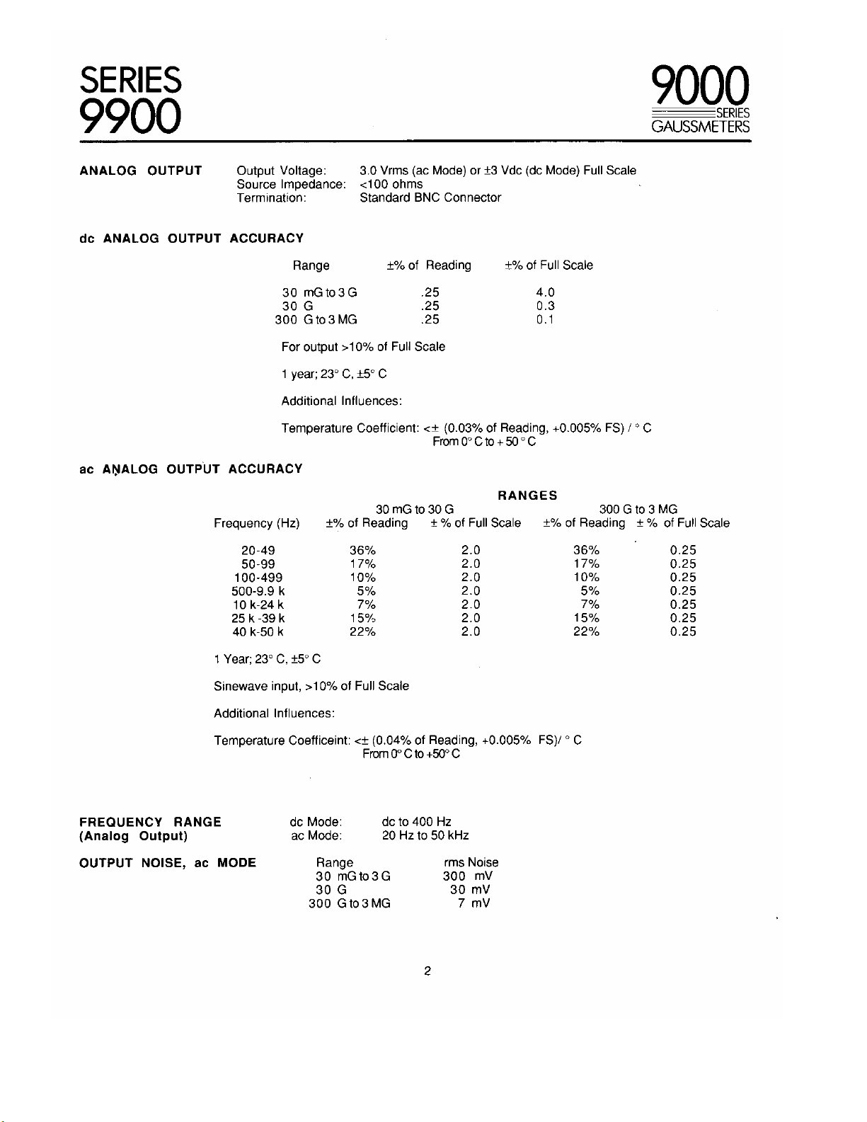
ANALOG OUTPUT
dc ANALOG OUTPUT ACCURACY
ac ANALOG OUTPUT ACCURACY
Output Voltage: 3.0 Vrms (ac Mode) or ±3 Vdc (dc Mode) Full Scale
Source Impedance: <100 ohms
Te r mi n a ti o n : Standard BNC Connector
30 mGto3G
30 G
300 G to 3 MG
For output >10% of Full Scale
1 year; 23° C, ±5° C
Additional Influences:
Te m pe r a t ur e Coefficient: <± (0.03% of Reading, +0.005% FS) I ° C
Frequency (Hz)
20-49 36%
50-99
100-499
500-9.9 k 5%
10 k-24 k
25 k -39 k
40 k-50 k
Range ±% of Reading ±% of Full Scale
.25 4.0
.25 0.3
.25 0.1
From 0° C to + 50 ° C
±% of Reading ± °/0 of Full Scale ±% of Reading ± % of Full Scale
30 mG to 30 G 300 G to 3 MG
17% 2.0 17%
10% 2.0
7% 2.0 7% 0.25
15% 2.0
22% 2.0 22% 0.25
RANGES
2.0 36% 0.25
10%
2.0 5% 0.25
15%
0.25
0.25
0.25
FREQUENCY RANGE
(Analog Output)
OUTPUT NOISE, ac MODE
1 Year; 23° C, ±5° C
Sinewave input, >10% of Full Scale
Additional Influences:
Te m pe r a t ur e Coefficeint: <± (0.04% of Reading, +0.005% FS)/ ° C
dc Mode:
ac Mode:
Range rms Noise
30 mGto3G 300 mV
30 G 30 mV
300 G to 3 MG 7 mV
From 0° C to +50° C
dc to 400 Hz
20 Hz to 50 kHz
2
SERIES
9900
9000
SERIES
GAUSSMETERS
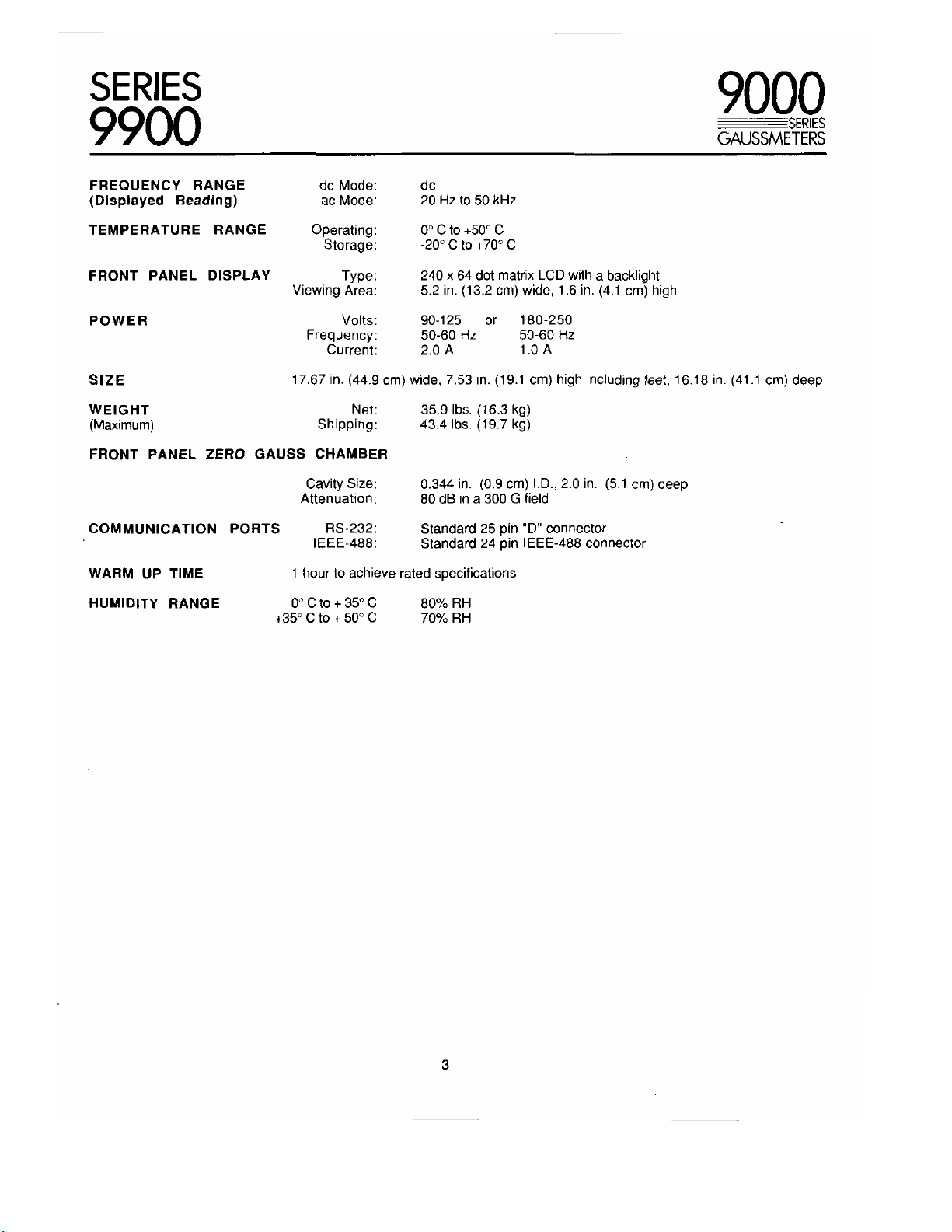
FREQUENCY RANGE
(Displayed Reading)
TEMPERATURE RANGE Operating: 0° C to +50° C
FRONT PANEL DISPLAY Type: 240 x 64 dot matrix LCD with a backlight
POWER Vo lts: 90-125 or 180-250
SIZE 17.67 in. (44.9 cm) wide, 7.53 in. (19.1 cm) high including feet, 16.18 in. (41.1 cm) deep
WEIGHT Net: 35.9 lbs. (16.3 kg)
(Maximum) Shipping: 43.4 lbs. (19.7 kg)
FRONT PANEL ZERO GAUSS CHAMBER
COMMUNICATION PORTS RS-232: Standard 25 pin "D" connector
WARM UP TIME 1 hour to achieve rated specifications
HUMIDITY RANGE
dc Mode: dc
ac Mode: 20 Hz to 50 kHz
Storage: -20° C to +70° C
Viewing Are a: 5.2 in. (13.2 cm) wide, 1.6 in. (4.1 cm) high
Frequency: 50-60 Hz 50-60 Hz
Current: 2.0 A 1.0 A
Cavity Size:
Attenuation:
IEEE-488: Standard 24 pin IEEE-488 connector
0°Cto+35°C 80% R H
+35° C to + 50° C 70°/0 R H
0.344 in. (0.9 cm) I.D., 2.0 in. (5.1 cm) deep
80 dB in a 300 G field
3
SERIES
9900
9000
SERIES
GAUSSMETERS
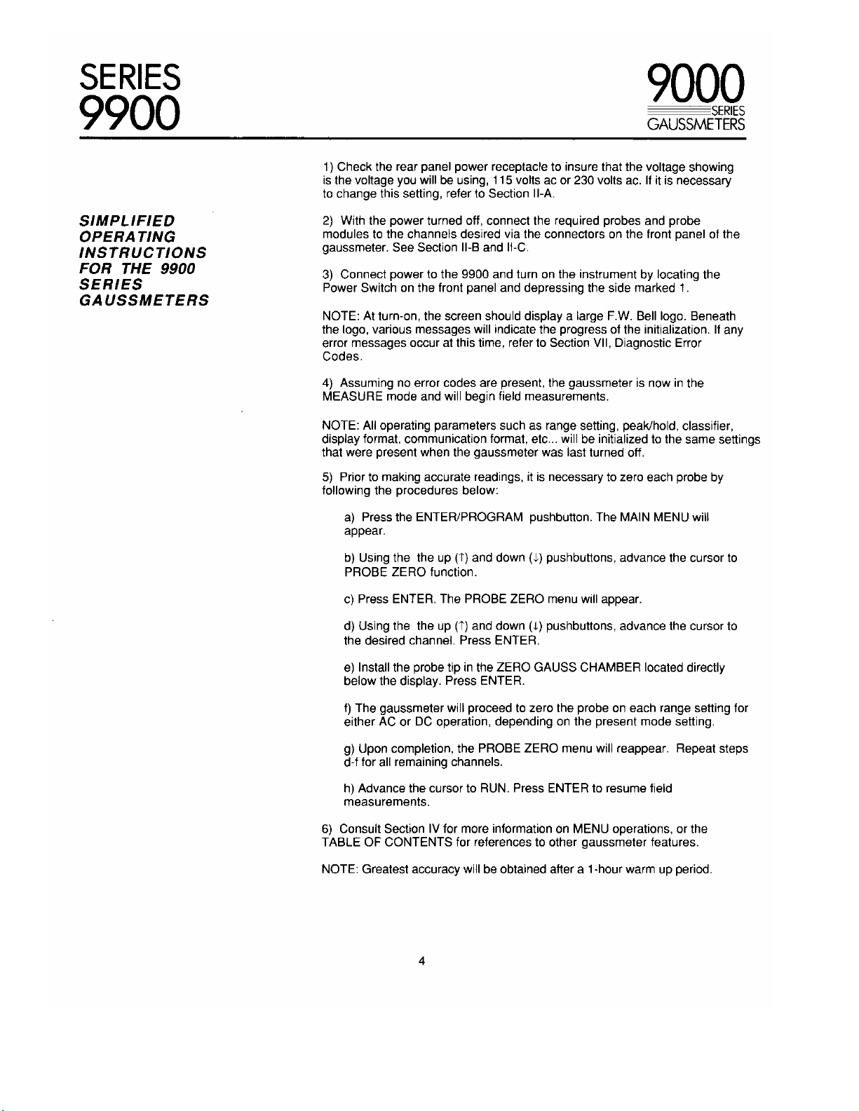
1) Check the rear panel power receptacle to insure that the voltage showing
is the voltage you will be using, 115 volts ac or 230 volts ac. If it is necessary
to change this setting, refer to Section II-A.
SIMPLIFIED
OPERATING
INSTRUCTIONS
FOR THE 9900
SERIES
GAUSSMETERS
2) With the power turned off, connect the required probes and probe
modules to the channels desired via the connectors on the front panel of the
gaussmeter. See Section II-B and II-C.
3) Connect power to the 9900 and turn on the instrument by locating the
Power Switch on the front panel and depressing the side marked 1.
NOTE: At turn-on, the screen should display a large F.W. Bell logo. Beneath
the logo, various messages will indicate the progress of the initialization. If any
error messages occur at this time, refer to Section VII, Diagnostic Error
Codes.
4) Assuming no error codes are present, the gaussmeter is now in the
MEASURE mode and will begin field measurements.
NOTE: All operating parameters such as range setting, peak/hold, classifier,
display format, communication format, etc... will be initialized to the same settings
that were present when the gaussmeter was last turned off.
5) Prior to making accurate readings, it is necessary to zero each probe by
following the procedures below:
a) Press the ENTER/PROGRAM pushbutton. The MAIN MENU will
appear.
b) Using the the up (T) and down (L) pushbuttons, advance the cursor to
PROBE ZERO function.
c) Press ENTER. The PROBE ZERO menu will appear.
d) Using the the up (T) and down (I) pushbuttons, advance the cursor to
the desired channel. Press ENTER.
e) Install the probe tip in the ZERO GAUSS CHAMBER located directly
below the display. Press ENTER.
f) The gaussmeter will proceed to zero the probe on each range setting for
either AC or DC operation, depending on the present mode setting.
g) Upon completion, the PROBE ZERO menu will reappear. Repeat steps
d-f for all remaining channels.
h) Advance the cursor to RUN. Press ENTER to resume field
measurements.
6) Consult Section IV for more information on MENU operations, or the
TABLE OF CONTENTS for references to other gaussmeter features.
NOTE: Greatest accuracy will be obtained after a 1-hour warm up period.
4
SERIES
9900
SECTION I I-A INTRODUCTION
The SERIES-9900 gaussmeter represents the latest developments in the
science of measuring magnetic flux density using the Hall effect. The unit is
GENERAL
DESCRIPTION
available in three configurations capable of processing a single channel
(Model 9901), two channels (Model 9902) or three channels (Model 9903) of
magnetic field information. Either steady-state (dc) or alternating (ac) fields
can be measured. When matched with the appropriate F.W. Bell fourth-
generation Hall generator probe, fields as low as 10 pG (0.0011.1T) or as high
as 2.9999 MG (299.99 T), at frequencies up to 50 kHz, can be measured with
extreme accuracy and 4-3/4 digit resolution.
The SERIES-9900 features PEAK HOLD, AU TORANGING, CLASSIFIER and
RELATIVE operation, auto ZEROing, GAUSS or TESLA readout, digital and
bargraph representation, diagnostics and remote operation with an IEEE-488
(GPIB) instrumentation bus and an RS-232 communications port. All
information is displayed on an illuminated graphics liquid crystal display (LCD).
The gaussmeter employs a menu-driven format to allow the user to program
all aspects of gaussmeter operation with ease and speed. Each gaussmeter
channel is completely and independently programmable.
I-B FUNCTIONAL DESCRIPTION
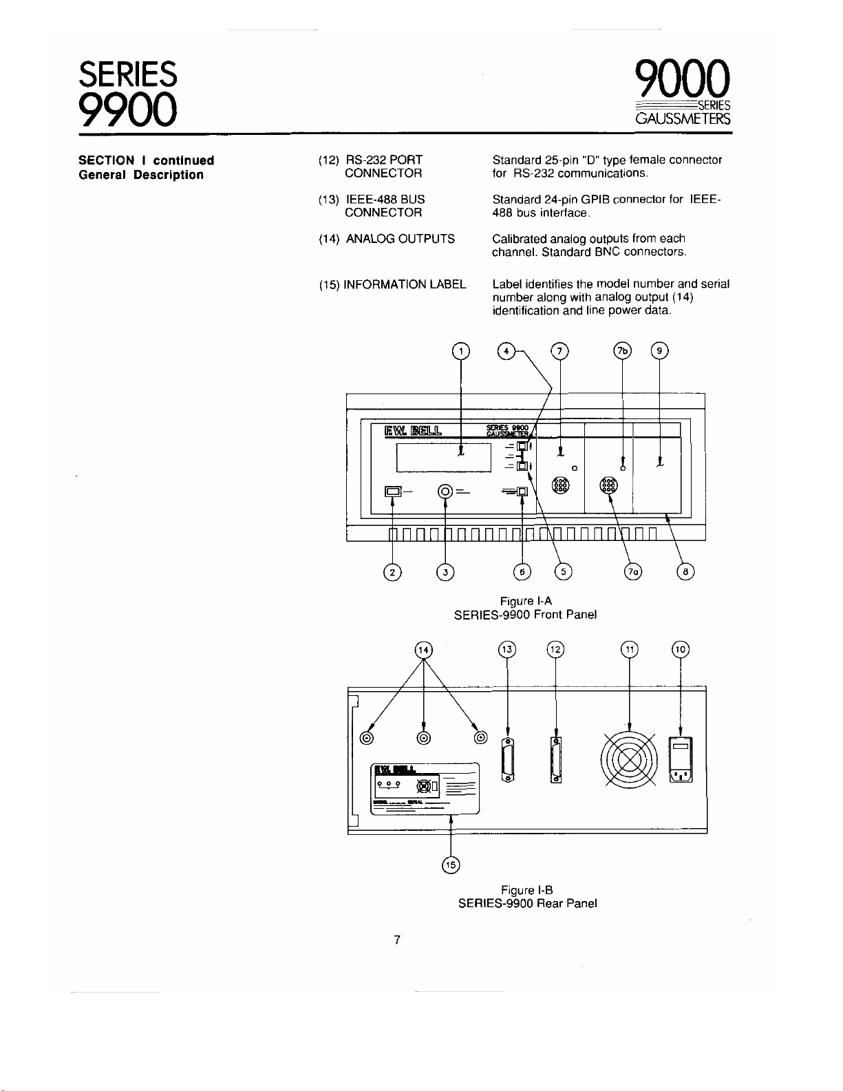
Figures I-A and I-B depict the SERIES-9900 front and rear panels,
respectively. The gaussmeter is housed in a standard 6.87" high x 17.67"
wide x 16.18" deep cabinet featuring pop-up feet for tabletop use and
(optional) brackets for rack mounting.
9000
SERIES
GAUSSMETERS
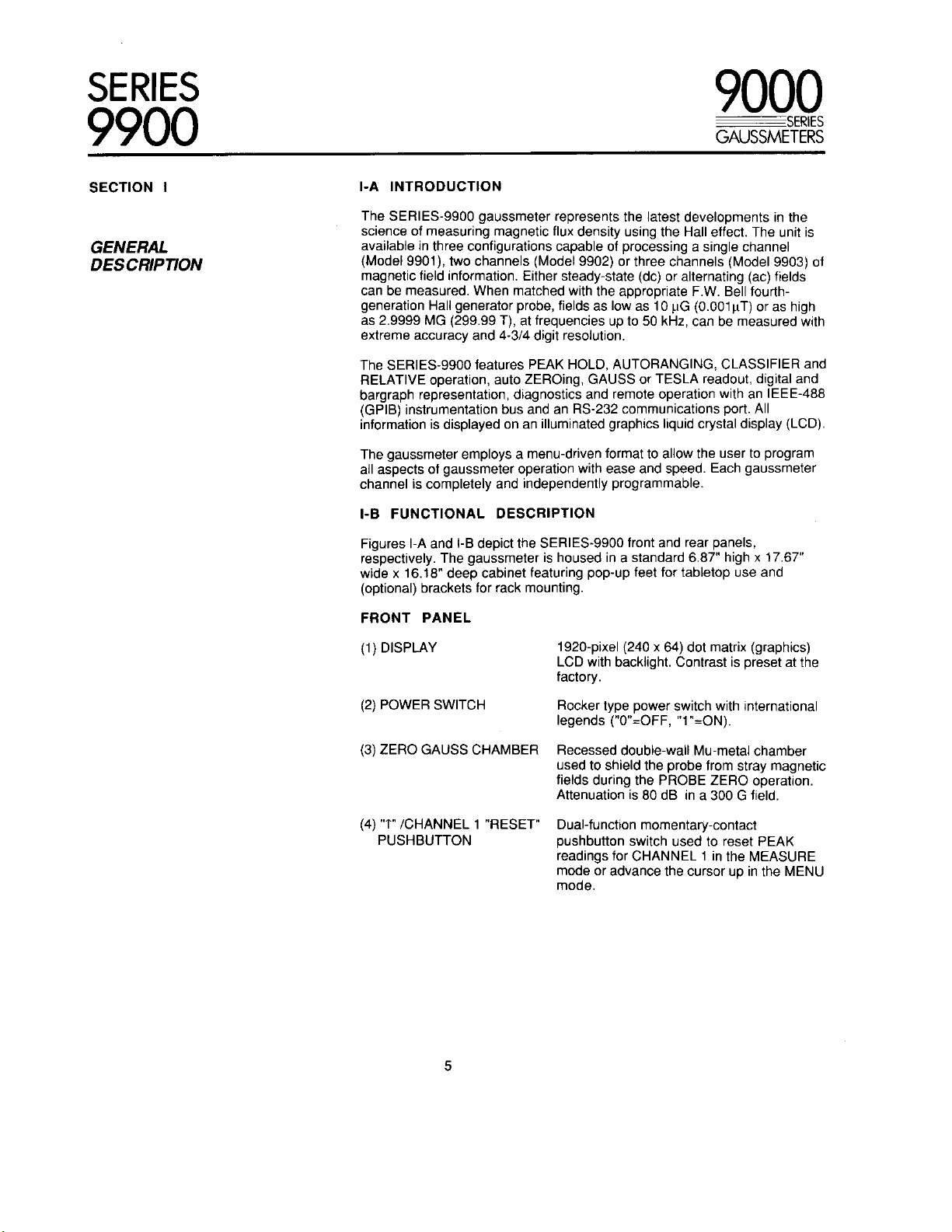
FRONT PANEL
(1) DISPLAY
(2) POWER SWITCH
(3) ZERO GAUSS CHAMBER
(4) "T" /CHANNEL 1 "RESET"
PUSHBUTTON
5
1920-pixel (240 x 64) dot matrix (graphics)
LCD with backlight. Contrast is preset at the
factory.
Rocker type power switch with international
legends ("0"=OFF, ''1"=ON).
Recessed double-wall Mu-metal chamber
used to shield the probe from stray magnetic
fields during the PROBE ZERO operation.
Attenuation is 80 dB in a 300 G field.
Dual-function momentary-contact
pushbutton switch used to reset PEAK
readings for CHANNEL 1 in the MEASURE
mode or advance the cursor up in the MENU
mode.

SERIES
9900
9000
SERIES
GAUSSMETERS
SECTION I continued
General Description
(5) "1" /CHANNEL 2 "RESET"
PUSHBUTTON
(6) "PROGRAM/ENTER"
PUSHBUTTON
(7) MODEL-99S PROBE
INTERFACE MODULE
(7-a) PROBE CONNECTOR
(7-b) ACTIV ITY INDICATOR
(8) INTERFACE MODULE
CAVITY
Dual-function momentary-contact
pushbutton switch used to reset PEAK
readings for CHANNEL 2 in the MEASURE
mode or advance the cursor down in the
MENU mode.
NOTE: Pressing both pushbuttons (4) and
(5) in the MEASURE mode will reset the
PEAK reading for CHANNEL 3.
Dual-function momentary-contact
pushbutton switch used to enter the MENU
mode and validate selections during MENU
operations.
Modular electronics package that accepts
fourth-generation Hall generator probe. Unit
interfaces to gaussmeter via a 64-pin dual-
row DIN connector.
9-pin twist-lock non-magnetic connector that
mates to F.W. Bell fourth-generation Hall
generator probes.
Red LED indicating module/probe activity.
Accepts MODEL-99S interface module (7)
or CAVITY blank panel (9). Cavity contains
an upper and lower card guide to ensure that
the interface module is properly aligned with
the rear mating connector.
WARNIN G! If a cavity is not used it must be
covered with a SERIES-9900 blank panel (9)
to ensure proper ventilation and protection
from contaminates. DO NOT USE
CAVITY AS A STORAGE AREA.
(9) CAVITY BLANK PANEL
REAR PANEL
(10) POWER RECEPTACLE/
FUSE HOLDER/
LINE VOLTAGE SWITCH
(11) VENTILATION FAN Regulates internal temperature of the
6
Used to cover an unused cavity (8). Order
F.W. Bell Item #338032.
This is a multi-purpose receptacle that
accepts an international instrumentation
power line cord. The middle (ground)
contact is connected to the chassis. This
receptacle also contains the line fuse,
storage space for a spare fuse and a line
voltage selector.
WARNIN G! See SECTION II before
applying power to the gaussmeter or
damage may result!▶
gaussmeter. DO NOT COVER !
SERIES
9900
9000
SERIES
GAUSSMETERS
SECTION I continued
General Description
(12) RS-232 PORT
CONNECTOR
(13) IEEE-488 BUS
CONNECTOR
(14) ANALOG OUTPUTS
(15) INFORMATION LABEL
Standard 25-pin "D" type female connector
for RS-232 communications.
Standard 24-pin GPIB connector for IEEE-
488 bus interface.
Calibrated analog outputs from each
channel. Standard BNC connectors.
Label identifies the model number and serial
number along with analog output (14)
identification and line power data.
0 0 0 0 0
E W. BELL
IM01111111111111111111111i11 I I I I I
SERIES Q900
= 1.1 1
= if
1
0 6 •-'
il! ,
0 0 0
Figure I-A
SERIES-9900 Front Panel
Figure I-B
SERIES-9900 Rear Panel
7
0 0
SERIES
9900
SECTION II II-A POWER RECEPTACLE
WARNING! READ THIS CAREFULLY
The SERIES-9900 gaussmeter has been factory-configured to operate on a
line voltage of 115 Vac. If operation at 230 Vac is required, perform the
following steps or damage may result.
9000
SERIES
GAUSSMETERS
SERIES-9900
GAUSSMETER PREPARATION
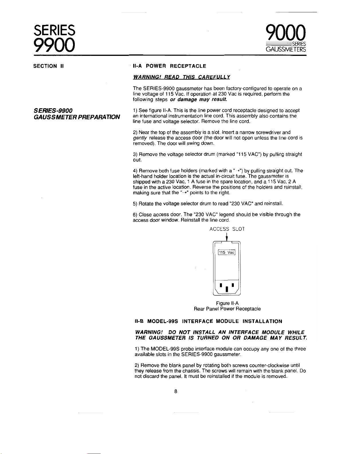
1) See figure II-A. This is the line power cord receptacle designed to accept
an international instrumentation line cord. This assembly also contains the
line fuse and voltage selector. Remove the line cord.
2) Near the top of the assembly is a slot. Insert a narrow screwdriver and
gently release the access door (the door will not open unless the line cord is
removed). The door will swing down.
3) Remove the voltage selector drum (marked "115 VAC") by pulling straight
out.
4) Remove both fuse holders (marked with a " 4") by pulling straight out. The
left-hand holder location is the actual in-circuit fuse. The gaussmeter is
shipped with a 230 Vac, 1 A fuse in the spare location, and a 115 Vac, 2 A
fuse in the active location. Reverse the positions of the holders and reinstall,
making sure that the "--," points to the right.
5) Rotate the voltage selector drum to read "230 VAC" and reinstall.
6) Close access door. The "230 VAC" legend should be visible through the
access door window. Reinstall the line cord.
ACCESS SLOT
115 Vac
Rear Panel Power Receptacle
II-B MODEL-99S INTERFACE MODULE INSTALLATION
WARNING! DO NOT INSTALL AN INTERFACE MODULE WHILE
THE GAUSSMETER IS TURNED ON OR DAMAGE MAY RESULT.
1) The MODEL-99S probe interface module can occupy any one of the three
available slots in the SERIES-9900 gaussmeter.
2) Remove the blank panel by rotating both screws counter-clockwise until
they release from the chassis. The screws will remain with the blank panel. Do
not discard the panel. It must be reinstalled if the module is removed.
8
Figure II-A
SERIES
9900
9000
SERIES
GAUSSMETERS
SECTION II continued
Gaussmeter Preparation
3) Locate the upper and lower card guides in the card rack. Install the module
so that the upper and lower card edges of the module mate with the card
guides. Slowly slide the module in until the rear connectors mate. Firmly push
the module into the chassis. Secure with the upper and lower screws.
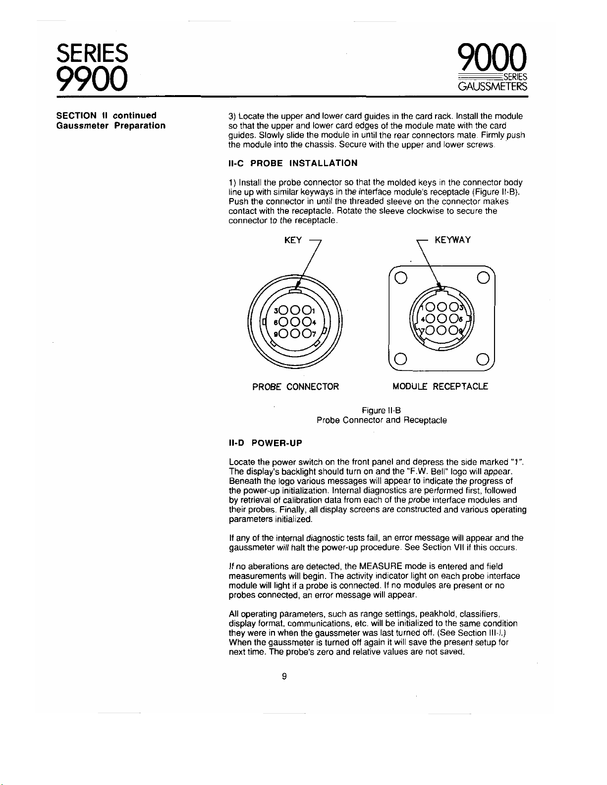
II-C PROBE INSTALLATION
1) Install the probe connector so that the molded keys in the connector body
line up with similar keyways in the interface module's receptacle (Figure II-B).
Push the connector in until the threaded sleeve on the connector makes
contact with the receptacle. Rotate the sleeve clockwise to secure the
connector to the receptacle.
0 0}
PROBE CONNECTOR
MODULE RECEPTACLE
Probe Connector and Receptacle
II-D POWER-UP
Locate the power switch on the front panel and depress the side marked "1".
The display's backlight should turn on and the "F.W. Bell" logo will appear.
Beneath the logo various messages will appear to indicate the progress of
the power-up initialization. Internal diagnostics are performed first, followed
by retrieval of calibration data from each of the probe interface modules and
their probes. Finally, all display screens are constructed and various operating
parameters initialized.
If any of the internal diagnostic tests fail, an error message will appear and the
gaussmeter will halt the power-up procedure. See Section VII if this occurs.
If no aberations are detected, the MEASURE mode is entered and field
measurements will begin. The activity indicator light on each probe interface
module will light if a probe is connected. If no modules are present or no
probes connected, an error message will appear.
All operating parameters, such as range settings, peakhold, classifiers,
display format, communications, etc. will be initialized to the same condition
they were in when the gaussmeter was last turned off. (See Section III-I.)
When the gaussmeter is turned off again it will save the present setup for
next time. The probe's zero and relative values are not saved.
9
Figure II-B
SERIES
9900
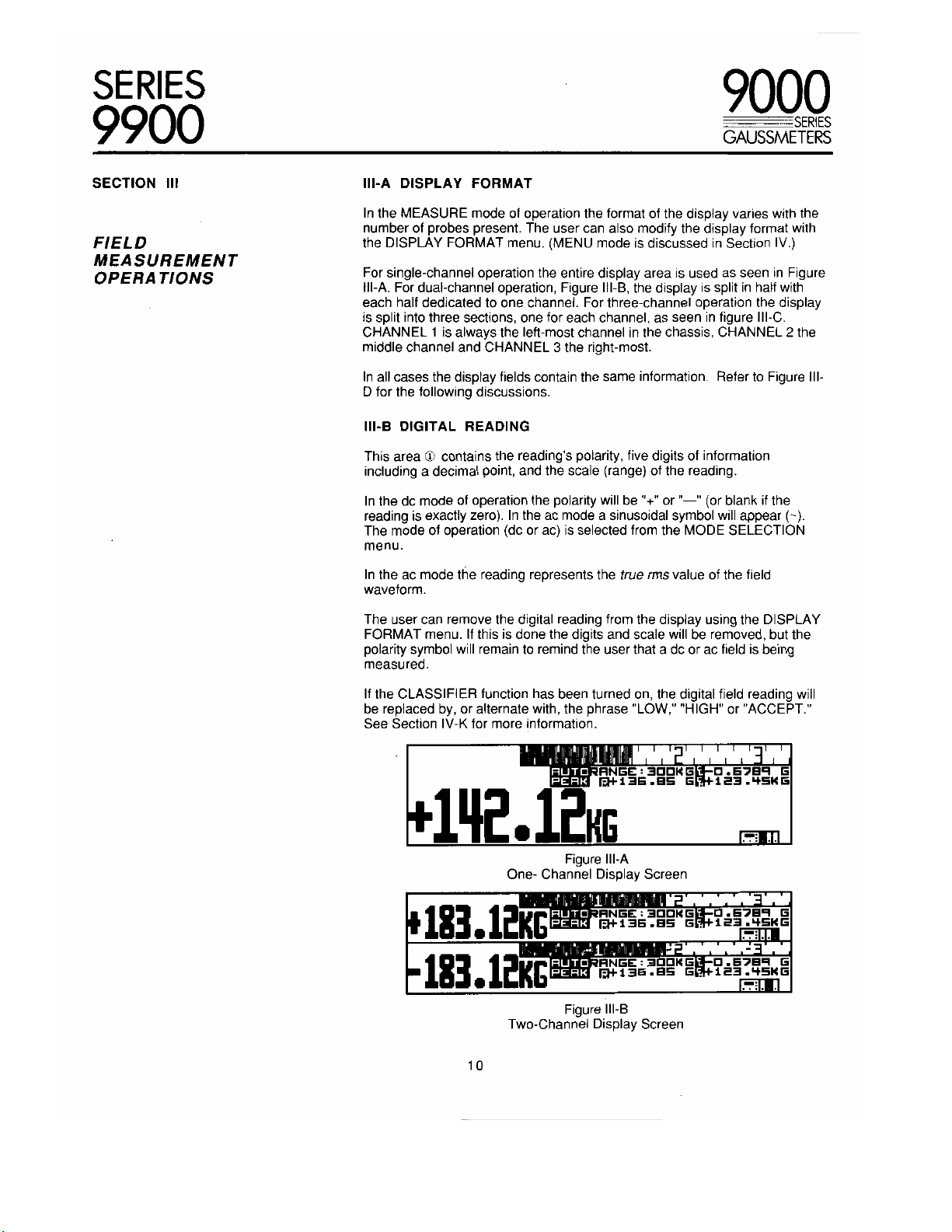
SECTION III III-A DISPLAY FORMAT
In the MEASURE mode of operation the format of the display varies with the
number of probes present. The user can also modify the display format with
FIELD
MEASUREMENT
OPERATIONS
the DISPLAY FORMAT menu. (MENU mode is discussed in Section IV.)
For single-channel operation the entire display area is used as seen in Figure
III-A. For dual-channel operation, Figure 111-B, the display is split in half with
each half dedicated to one channel. For three-channel operation the display
is split into three sections, one for each channel, as seen in figure III-C.
CHANNEL 1 is always the left-most channel in the chassis, CHANNEL 2 the
middle channel and CHANNEL 3 the right-most.
In all cases the display fields contain the same information. Refer to Figure III-
D for the following discussions.
III-B DIGITAL READING
This area 0 contains the reading's polarity, five digits of information
including a decimal point, and the scale (range) of the reading.
In the dc mode of operation the polarity will be "+" or "—" (or blank if the
reading is exactly zero). In the ac mode a sinusoidal symbol will appear (-).
The mode of operation (dc or ac) is selected from the MODE SELECTION
menu.
9000
SERIES
GAUSSMETERS
In the ac mode the reading represents the true rms value of the field
waveform.
The user can remove the digital reading from the display using the DISPLAY
FORMAT menu. If this is done the digits and scale will be removed, but the
polarity symbol will remain to remind the user that a dc or ac field is being
measured.
If the CLASSIFIER function has been turned on, the digital field reading will
be replaced by, or alternate with, the phrase "LOW," "HIGH" or "ACCEPT."
See Section IV-K for more information.
11111111 I in, I I F JnuTin-RNGE:EDDNG D.67B9 G
PERK iii3E.GE G. 123.4SWG
1.1.112 12H
One- Channel Display Screen
18361 G
11 3 . 12KG
Two -Channel Display Screen
Figure 111-A
AUTO
PERK
AUTO
PERK
Figure III-B
I I L
FAGE:3=4G 13.67139 c
M+136.85 G. 123.4514c
RNGE:31:1014G 0.67Eg G
M*136.8S G. 123.4514G
LIFZIMONIIIMMON
WIN
10
SERIES
9900
9000
SERIES
GAUSSMETERS
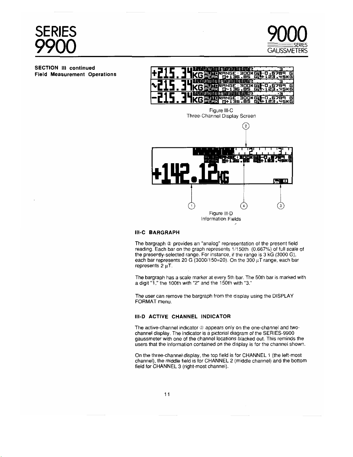
SECTION III continued
Field Measurement Operations
Ill-C BARGRAPH
1 1r %.11LJa11 L, a if W40'1U If! trilMOMMOMFMMIO
AUTO—I:INGE:30014Si 0.6789 G
PERK p 136.85 G. 123.45KG
IL now lui ffivalumt ul IN g meliffINMOREIIINJ
AUTO RNSE:300KG4_
PERK p 136.85 651
motimuktnuliffivuNISMINMERWMMO
AUTO I:INGE:3001MT. 0.6789 G
PERK p 136.85 Gia 123.46KG
Three-Channel Display Screen
S
Figure III-C
WIZEN LEE • IFEN
0.6789 G
123.45KG
..M71119
0 0
Figure III-D
Information Fields
The bargraph provides an "analog" representation of the present field
reading. Each bar on the graph represents 1/150th (0.667%) of full scale of
the presently-selected range. For instance, if the range is 3 kG (3000 G),
each bar represents 20 G (3000/150=20). On the 300 µ-1- range, each bar
represents 2 µT.
The bargraph has a scale marker at every 5th bar. The 50th bar is marked with
a digit "1," the 100th with "2" and the 150th with "3."
The user can remove the bargraph from the display using the DISPLAY
FORMAT menu.
III-D ACTIVE CHANNEL INDICATOR
The active-channel indicator ® appears only on the one-channel and two-
channel display. The indicator is a pictorial diagram of the SERIES-9900
gaussmeter with one of the channel locations blacked out. This reminds the
users that the information contained on the display is for the channel shown.
On the three-channel display, the top field is for CHANNEL 1 (the left-most
channel), the middle field is for CHANNEL 2 (middle channel) and the bottom
field for CHANNEL 3 (right-most channel).
11
SERIES
9900
SECTION III continued III-E INFORMATION BLOCK
Field Measurement Operations
The information block ® contains various annunciators and information
about the present state of the channel as follows:
9000
SERIES
GAUSSMETERS
"AUTO" ANNUNCIATOR
"PEAK" ANNUNCIATOR
RANGE SETTING The present range setting for the channel.
RELATIVE OFFSET
CLASSIFIERS
III-F CHANNEL DEACTIVATION
In some cases the user may have several channels installed but may be
interested in observing only one or two. A channel can be deactivated by
turning off both the digital reading and the bargraph via the DISPLAY
FORMAT menu, or by disconnecting the probe from the interface module.
This places the channel in a standby position and removes it from the display.
For instance if all three channels are present and CHANNEL 2 is deactivated,
the gaussmeter will automatically reformat for a two-channel display;
CHANNEL 1 on the top half and CHANNEL 3 on the bottom half of the
display.
If the autoranging function has been turned on
(RANGE SELECT menu), the "AUTO"
annunciator will be present.
If the PEAK HOLD function has been turned on
(PEAK HOLD menu), the "PEAK" annunciator
will be present. The "PEAK" annunciator is also
used to indicate a particular overrange condition
as described in Section li I-G.
This field contains the RELATIVE field reading
that was present when the PROBE RELATIVE
operation began (See PROBE RELATIVE
menu). The reading is preceded by the "R"
annunciator. If the RELATIVE function is turned
off this field will be blank.
These fields contain the user-defined
CLASSIFIER settings preceded by the C/L and
C/H annunciators. If the CLASSIFIER function
has been turned off these fields will be blank.
In the REMOTE mode of operation, field measurements are not possible
unless the deactivated channel is reactivated. This can be accomplished from
the remote device (see Section V).
III-G OVERRANGE CONDITIONS
If the present field density exceeds the present range of the gaussmeter
both the digital reading and the bargraph will flash. Overrange occurs when
the magnitude of the reading exceeds 29999 (2.9999 kG, 299.99 T, etc.).
Field readings will continue up to about 9% higher than this magnitude, or
32767.
In some instances the magnetic field being measured may contain spikes or
ripples that cause the present range to be exceeded even though the
average reading is within limits. When this occurs the "PEAK" annunciator will
flash to indicate that the displayed reading may be inaccurate and a higher
range should be used.
12
SERIES
9900
9000
SERIES
GAUSSMETERS
SECTION III continued
Field Measurement Operations
III-H PEAK HOLD OPERATION
When the PEAK HOLD function is engaged (via the PEAK HOLD menu) the
largest absolute field reading will be held on the display. For instance a
+200.00 G reading will replace a +100.00 G reading and be held, and a
-250.00 G reading will replace the previously-held +200.00 G reading.
The user can reset a held reading at any time by pressing and releasing that
channel's RESET pushbutton on the front panel. As the pushbutton is
pressed the ''PEAK" annunciator will flash to indicate that the reset command
has been recognized but the actual reset operation will not occur until the
pushbutton is released.
One pushbutton is dedicated to resetting CHANNEL 1, another for
CHANNEL 2 and both for CHANNEL 3. In the case of a CHANNEL 3 reset,
the user might press one pushbutton before the other, say CHANNEL 1
before CHANNEL 2. In this case the CHANNEL 1 "PEAK" annunciator will
flash. As soon as the CHANNEL 2 pushbutton is pressed the CHANNEL 1
annunciator will return to normal and the CHANNEL 3 annunciator will flash.
This will not cause a problem since the actual resetting operation will not
occur until both pushbuttons are released, properly resetting CHANNEL 3's
peak reading only.
III-I POWER UP INITIALIZATION
The gaussmeter permanently stores each channel's MEASURE mode setup.
When the gaussmeter is powered off and on again, the previous settings are
restored and the gaussmeter is reinitialized to those settings. The following
information is saved:
• MODE (ac/dc A ND GAUSS/TESLA)
• RANGE SETTING (INCLUDING AUTORANGE)
• PEAK HOLD ON/OFF (LAST PEAK READING WILL NOT BE SAVED)
• CLASSIFIER SETTINGS
• CLASSIFIER ON/OFF STATUS
• DIGITS ON/OFF
• BARGRAPH ON/OFF
• BACKLIGHT ON/OFF
• IEEE-488 PRIMARY ADDRESS
• RS-232 PARITY, STOP BITS, CHARACTER LENGTH AND BAUD RATE
The RELATIVE mode will be turned off and the relative offset will be reset to
zero.
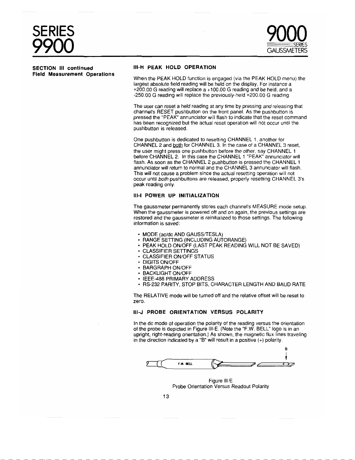
III-J PROBE ORIENTATION VERSUS POLARITY
In the dc mode of operation the polarity of the reading versus the orientation
of the probe is depicted in Figure III-E. (Note the "F.W. BELL" logo is in an
upright, right-reading orientation.) As shown, the magnetic flux lines traveling
in the direction indicated by a "B" will result in a positive (+) polarity.
B
=Cr BELL
Figure III-E
Probe Orientation Versus Readout Polarity
13
C

SERIES
9900
SECTION III continued III-K ANALOG OUTPUTS
Field Measurement Operations
On the rear panel of the gaussmeter are connections that, when connected
to an oscilloscope, allow the user to observe the actual magnetic field
waveforms.
In the ac mode, the waveform is the actual field waveform calibrated to 3 volts
rms full scale. For instance, with the gaussmeter programmed for a 3 kG range
setting (3000 G) a 2.0000 Vrms signal correlates to a 2.0000 kG field density.
In the dc mode, the output is instantaneously proprotional to the field in
magnitude and polarity from dc to 400 Hz.
NOTE: The gaussmeter digitally corrects the magnetic field density signals for
errors due to probe offset, amplifier offset, frequency-related attenuation,
temperature-related effects, etc. before the final reading is displayed. The
signals available at the ANALOG OUTPUT connectors ARE NOT
CORRECTED for these errors.
III-L REMOTE TERMINAL ("MASTER") OPERATION
There are two modes of remote operation available in the SERIES-9900
gaussmeter. In the "SLAVE" mode, available from either the RS-232 serial
port or the IEEE-488 bus, a remote device (typically a computer system or
industrial controller) controls all gaussmeter operations. This is discussed in
Section V.
9000
SERIES
GAUSSMETERS
In the "MASTER" mode, available only from the RS-232 serial port, the
gaussmeter controls a remote terminal or printer device. This is particularly
useful if the the user and gaussmeter must be separated by some distance,
or if the user wishes to have a hardcopy of all gaussmeter activity.
The terminal/printer may be connected directly to the gaussmeter, or
indirectly through a modem following the electrical connections shown in
Section VI. The RS-232 characteristics of both devices must match. The
gaussmeters' parameters can be modified via the COMMUNICATIONS
FORMAT menu. All MEASURE mode and MENU mode operations are
accessible from the terminal. See Section IV-M for further information.
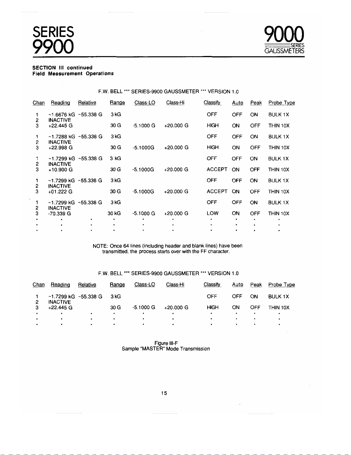
Whenever field measurements are taking place the gaussmeter will transmit a
continuous listing of field measurements and channel status in a formatted
ASCII character stream as shown in Figure Ill-F. Note that CHANNEL 1 is
programmed for the RELATIVE mode, CHANNEL 2 has been deactivated
and CHANNEL 3 has been programmed for CLASSIFIER operation.
CHANNEL 1 has a 1X bulk Hall generator probe attached, CHANNEL 3 a 10X
thin film device.
Initially, a FORMFEED (FF) control character is transmitted. If a printer is
connected this should cause the paper feeder to advance to the top of the
next sheet of paper. If a terminal is connected this usually clears the screen.
The FF is followed by CARRIAGE RETURN (CR) and LINEFEED (LF) control
character and then a three-line header containing 79 printable characters per
line. Each line is followed by a CR and LF.
Each line of measurement data contains 79 printable AS CII characters
followed by a CR and LF. The third (CHANNEL 3) information line is followed
by one more LF to create a blank line between each group of readings.
14
SERIES
9900
SECTION III continued
Field Measurement Operations
F. W. BELL *** SERIES-9900 GAUSSMETER *** VERSION 1.0
9000
SERIES
GAUSSMETERS
Chan
Reading Relative Range Class-LO Class-Hi Classify Auto
1 -1.6676 kG -55.338 G 3 kG OFF
INACTIVE
2
3 +22.445 G 30 G -5.1000 G +20.000 G
1 -1.7288 kG -55.338 G 3 kG
2 INACTIVE
3
+22.998 G 30 G -5.1000G
1 -1.7299 kG -55.338 G 3 kG
2 INACTIVE
+10.900 G
3
1
-1.7299 kG -55.338 G
INACTIVE
2
+01.222 G
3
1 -1.7299 kG -55.338 G 3 kG
2 INACTIVE
3
-70.339 G
• • •
30 G -5.1000G
3 kG OFF OFF
30 G
30 kG -5.1000 G +20.000 G LOW ON OFF THIN 10X
NOTE: Once 64 lines (including header and blank lines) have been
transmitted, the process starts over with the FF character.
-5.1000G
+20.000 G HIGH
+20.000 G ACCEPT ON OFF
+20.000 G ACCEPT
OFF
HIGH ON
OFF
OFF OFF
OFF OFF
OFF ON BULK 1X
ON OFF THIN 10X
ON OFF THIN 10X
Peak Probe Type
ON BULK 1X
OFF THIN 10X
ON BULK 1X
THIN 10X
ON BULK 1X
ON BULK 1X
F. W. BELL *** SERIES-9900 GAUSSMETER *** VERSION 1.0
Chan Reading Relative Range Class-LO Class-Hi Classify Au to Peak Probe Type
1 -1.7299 kG -55.338 G 3 kG OFF OFF ON BULK 1X
2 INACTIVE
3 +22.445 G 30 G -5.1000 G +20.000 G HIGH ON OFF THIN 10X
• •
•
Figure III-F
Sample "MASTER" Mode Transmission
15
•
SERIES
9900
9000
SERIES
GAUSSMETERS
SECTION III continued
Field Measurement Operations
DISPLAY UPDATE
(CHANNEL1)
+23.998 kG
+24.220 kG
+25.770 kG
+24.556 kG
+24.234 kG
+21.002 kG
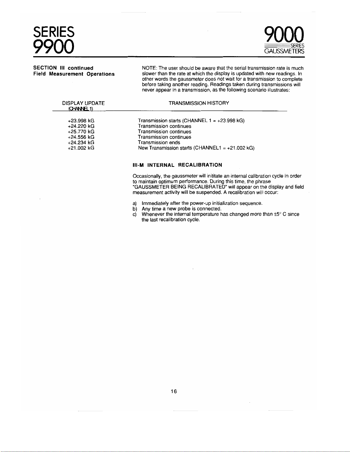
NOTE: The user should be aware that the serial transmission rate is much
slower than the rate at which the display is updated with new readings. In
other words the gaussmeter does not wait for a transmission to complete
before taking another reading. Readings taken during transmissions will
never appear in a transmission, as the following scenario illustrates:
TRANSMISSION HISTORY
Transmission starts (CHANNEL 1 = +23.998 kG)
Transmission continues
Transmission continues
Transmission continues
Transmission ends
New Transmission starts (CHANNEL1 = +21.002 kG)
III-M INTERNAL RECALIBRATION
Occasionally, the gaussmeter will inititate an internal calibration cycle in order
to maintain optimum performance. During this time, the phrase
"GAUSSMETER BEING RECALIBRATED" will appear on the display and field
measurement activity will be suspended. A recalibration will occur:
a) Immediately after the power-up initialization sequence.
b) Any time a new probe is connected.
c) Whenever the internal temperature has changed more than ±5° C since
the last recalibration cycle.
16
 Loading...