

F.W. Bell 8000 series Instruction Manual

8000 SERIES GAUSS / TESLA METER
Instruction
Manual

THIS SIDE BLANK !
(Inside of Front Cover)

8000 Series
GAUSS / TESLA METER
Instruction Manual
Manual UN-01-270
Rev. B
February, 2017
Applicable System Firmware Release 1.6.2
All Rights Reserved.
Environmental Considerations
End-of-Life Handling of Product
This equipment may contain substances which could be harmful to the
environment or human health if not disposed of properly when it has reached
the end of its useful life. We encourage you to recycle this product through a
system which will ensure recycling of most of the materials in an appropriate
manner.
The crossed out wheeled trash bin symbol indicates compliance with the
European Union Directives 2012/19/EU and 2006/66/EC on Waste Electrical
and Electronic Equipment (WEEE) and batteries.
For information on recycling options please check the Meggitt Sensing
Systems Recycling website:
http://www.meggittsensingsystems.com/WEEE/recycling/index.html
RoHS Compliance
The 8000 Series Gaussmeters and probes meet the RoHS 2011/65/EU
Directive on the Reduction of Hazardous Substances.

This symbol appears on the instrument and probe. It refers the
operator to additional information contained in this instruction
manual, also identified by the same symbol.
NOTICE:
See Pages 4-1, 4-2, and 4-3 for SAFETY
instructions prior to first use!
See Page 2-4 for EMC Notes concerning I/O
Cables and I/O Filter Adapters

F.W. BELL 8000 Series Gauss/Tesla Meter Instruction Manual
TABLE OF CONTENTS
TABLE OF CONTENTS ................................................................................................... i
LIST OF TABLES .......................................................................................................... iv
LIST OF ILLUSTRATIONS ............................................................................................. v
SECTION 1 Introduction ............................................................................................ 1-1
Overview ................................................................................................................... 1-1
General Description .................................................................................................. 1-3
Applications .............................................................................................................. 1-8
SECTION 2 Specifications ......................................................................................... 2-1
Meter Specifications ................................................................................................. 2-1
Communications ....................................................................................................... 2-4
Regulatory Information ............................................................................................. 2-5
Calibration Service .................................................................................................... 2-5
Zero Flux Chambers ................................................................................................. 2-6
SECTION 3 Probes ..................................................................................................... 3-1
Overview ................................................................................................................... 3-1
Probe Variations ....................................................................................................... 3-2
Probe ........................................................................................................................ 3-3
Memory ..................................................................................................................... 3-3
Probe Stem ............................................................................................................... 3-3
Temperature Effects ................................................................................................. 3-3
Fixturing .................................................................................................................... 3-3
8000 Series Probes .................................................................................................. 3-4
SECTION 4 Setup ....................................................................................................... 4-1
Safety Instructions .................................................................................................... 4-1
Line Voltage Settings / Fuse Panel ........................................................................... 4-3
Adjusting the Handle & Feet ..................................................................................... 4-4
Probe Installation / Removal ..................................................................................... 4-5
Power-Up .................................................................................................................. 4-6
SECTION 5 User Interface ......................................................................................... 5-1
Overview ................................................................................................................... 5-1
Front Panel Keypad .................................................................................................. 5-2
Menu System ............................................................................................................ 5-3
Display System Information .................................................................................. 5-6
User Setup Save and Recall ................................................................................. 5-6
Setting the Date and Time .................................................................................... 5-8
Display Errors........................................................................................................ 5-9
Power On Options ................................................................................................. 5-9
i

F.W. BELL 8000 Series Gauss/Tesla Meter Instruction Manual
SECTION 6 Flux Density Measurement .................................................................... 6-1
Overview ................................................................................................................... 6-1
Measurement Units ................................................................................................... 6-2
Flux Density Reading ................................................................................................ 6-3
Measurement Range Selection ................................................................................ 6-3
Measurement Mode Selections ................................................................................ 6-4
DC Mode Operation .............................................................................................. 6-5
AC Mode Operation .............................................................................................. 6-5
Zeroing ..................................................................................................................... 6-8
Display Update Interval ........................................................................................... 6-12
Hold Function ......................................................................................................... 6-13
Relative Mode ......................................................................................................... 6-15
Vector Summation .................................................................................................. 6-18
Analog Outputs ....................................................................................................... 6-21
Classifier Outputs ................................................................................................... 6-24
Sources of Measurement Error ............................................................................... 6-25
SECTION 7 AC Waveform Display ............................................................................ 7-1
Introduction ............................................................................................................... 7-1
AC Waveform Display Graphical Layout ................................................................... 7-1
Accessing the AC Waveform Display ....................................................................... 7-2
Setting the Time Base .............................................................................................. 7-2
Setting the Vertical Scale .......................................................................................... 7-3
Trigger Operation ...................................................................................................... 7-4
Trigger Channel Selection ..................................................................................... 7-5
Trigger Modes ....................................................................................................... 7-5
Free Run ........................................................................................................... 7-5
Auto ................................................................................................................... 7-5
Repeat ............................................................................................................... 7-5
Single ................................................................................................................ 7-5
Trigger Slope......................................................................................................... 7-6
Trigger Level ......................................................................................................... 7-6
SECTION 8 Remote Operation .................................................................................. 8-1
Introduction ............................................................................................................... 8-1
Communications Ports .............................................................................................. 8-2
RS-232 Port .......................................................................................................... 8-2
Functional Description ....................................................................................... 8-2
Configuration ..................................................................................................... 8-3
Ethernet Port ......................................................................................................... 8-4
Functional Description ....................................................................................... 8-4
Configuration ..................................................................................................... 8-5
Accessing the System with TELENET Client ..................................................... 8-6
Internal Web Application ....................................................................................... 8-7
Accessing the Internal Web Application ............................................................ 8-7
Functional Description ....................................................................................... 8-8
IEEE-488 (GPIB) BUS ........................................................................................ 8-10
ii

F.W. BELL 8000 Series Gauss/Tesla Meter Instruction Manual
Functional Description ..................................................................................... 8-10
Implementation ................................................................................................ 8-11
Configuration ................................................................................................... 8-12
Status Registers and Error Queue .......................................................................... 8-13
Status Registers .................................................................................................. 8-13
Status Byte and Service Request (SRQ) ............................................................ 8-14
Error Queue ........................................................................................................ 8-15
Standard Event Register ..................................................................................... 8-16
Measurement Event Register .............................................................................. 8-16
Operation Event Register .................................................................................... 8-17
Questionable Event Register .............................................................................. 8-17
Remote SCPI Commands ...................................................................................... 8-18
IEEE - 488.2 “Common” Command Syntax ........................................................ 8-18
IEEE-488.2 “Common” Command Descriptions .................................................. 8-19
SCPI Command Syntax ...................................................................................... 8-22
SCPI Message Terminators ................................................................................ 8-23
SCPI Meter Specific Commands ......................................................................... 8-23
SCPI Command Descriptions ............................................................................. 8-27
SECTION 9 Data Logging Utilities ............................................................................. 9-1
Overview ................................................................................................................... 9-1
Logging Data ............................................................................................................ 9-2
Logging to USB Drive ............................................................................................ 9-2
Logging to Internal Drive ....................................................................................... 9-2
Screen Capture ........................................................................................................ 9-3
SECTION 10 Firmware Update ................................................................................ 10-1
Overview ................................................................................................................. 10-1
Firmware Update Procedure ................................................................................... 10-1
Preparing the USB Drive for Update ................................................................... 10-1
APPENDIX A Understanding Flux Density .......................................................... A-1
Measurement of Flux Density ................................................................................... A-2
APPENDIX B Vector Summation Tutorial ............................................................ B-1
APPENDIX C Error Codes ..................................................................................... C-1
APPENDIX D WARRANTY .................................................................................... D-1
iii

F.W. BELL 8000 Series Gauss/Tesla Meter Instruction Manual
LIST OF TABLES
Table 1-1 8000 Series Gauss/Tesla Meter List of Features ...................................... 1-2
Table 1-2 Front Panel Description ............................................................................. 1-6
Table 1-3 Rear Panel Description ............................................................................. 1-7
Table 2-1 Ranges for Low Field Probes .................................................................... 2-1
Table 2-2 Ranges for Mid Field Probes ..................................................................... 2-1
Table 2-3 Ranges for High Field Probes ................................................................... 2-1
Table 2-4 Accuracies at 23˚C ±2C˚ (Meter Only) ...................................................... 2-3
Table 2-5 Classifier Connections .............................................................................. 2-4
Table 3-1 Probe Maximum Field Levels and Resolutions ......................................... 3-2
Table 5-1 Menu Key Operation Descriptions ............................................................. 5-3
Table 5-3 Default Configuration Settings ................................................................... 5-7
Table 5-4 12-hour to 24-hour Conversion Chart ........................................................ 5-8
Table 6-1 Available Units .......................................................................................... 6-2
Table 6-2 Minimum Magnitudes for Rated AC Accuracy ........................................... 6-6
Table 6-3 AC Mode Analog Filter Selections ............................................................. 6-7
Table 6-4 Estimated Zeroing Times .......................................................................... 6-9
Table 6-5 Update Interval Settings .......................................................................... 6-12
Table 7-1 Time Base Selections for AC Filter Settings .............................................. 7-3
Table 8-1 RS-232 Port Settings ................................................................................ 8-4
Table 8-2 Common Command Summary ................................................................ 8-19
Table 8-3 SCPI Error Queue Commands ................................................................ 8-24
Table 8-4 SCPI System Information and Configuration Commands ....................... 8-24
Table 8-5 SCPI Status Register Commands ........................................................... 8-24
Table 8-6 SCPI Unit Commands ............................................................................. 8-24
Table 8-7 SCPI Range and Mode Commands ........................................................ 8-24
Table 8-8 SCPI Display Update Rate Command .................................................... 8-25
Table 8-9 SCPI Classifier (Limit) Commands .......................................................... 8-25
Table 8-10 SCPI Measurement Commands ............................................................ 8-25
Table 8-11 SCPI Filter Commands .......................................................................... 8-25
Table 8-12 SCPI Zeroing Commands ..................................................................... 8-26
Table 8-13 SCPI Relative Offset Commands .......................................................... 8-26
Table 8-14 SCPI Analog Output Commands ........................................................... 8-26
Table 8-15 SCPI Vector Summation Command ...................................................... 8-26
Table 8-16 SCPI Hold Commands .......................................................................... 8-26
Table 8-17 Operating Ranges with Various Probes ................................................ 8-31
Table 9-1 Sample Data Log ...................................................................................... 9-1
iv

F.W. BELL 8000 Series Gauss/Tesla Meter Instruction Manual
LIST OF ILLUSTRATIONS
Figure 1-1 Front Panel (8010 Model Shown) ............................................................ 1-6
Figure 1-2 Rear Panel (8010 Model Shown) ............................................................. 1-7
Figure 1-3 Various Positions of Meter ....................................................................... 1-8
Figure 2-1 Frequency Response of Uncorrected Analog Output ............................... 2-3
Figure 2-2 Digital I/O Connector ................................................................................ 2-4
Figure 2-3 YA-111 Zero Flux Chamber ..................................................................... 2-6
Figure 2-4 YA-112 Zero Flux Chamber ..................................................................... 2-6
Figure 3-1 8000 Series Probe Model Chart ............................................................... 3-2
Figure 3-2 Hall Probe Configurations ........................................................................ 3-4
Figure 4-1 Probe Electrical Warning .......................................................................... 4-2
Figure 4-2 Fuse Replacement ................................................................................... 4-3
Figure 4-3 Adjusting the Handle and Feet ................................................................. 4-4
Figure 4-4 Installing and Removing Probes .............................................................. 4-5
Figure 4-5 Standby Button Location .......................................................................... 4-6
Figure 4-6 Boot Up Screen ........................................................................................ 4-7
Figure 5-1 Front Panel Key Sets ............................................................................... 5-2
Figure 5-2 Main Menu Example ................................................................................ 0-3
Figure 5-3 Menu Selections Example ........................................................................ 5-4
Figure 5-4 Special Menu Screens ............................................................................. 5-4
Figure 5-5 8000 Gaussmeter Menu Map ................................................................... 5-5
Figure 6-1 Setting the Units ....................................................................................... 6-2
Figure 6-2 Flux Density Reading ............................................................................... 6-3
Figure 6-3 Range Settings ........................................................................................ 6-3
Figure 6-4 Measurement Mode Selection ................................................................. 6-5
Figure 6-5 Frequency / Period Indicator .................................................................... 6-5
Figure 6-6 Analog Filter Selection ............................................................................. 6-7
Figure 6-7 Auto Zero Menu Path ............................................................................. 6-10
Figure 6-8 Manual Zero Menu Path ......................................................................... 6-11
Figure 6-9 Update Interval Setting........................................................................... 6-12
Figure 6-10 Hold Features Settings......................................................................... 6-14
Figure 6-11 Relative Value Indicator ....................................................................... 6-16
Figure 6-12 Relative Settings Menu Path ................................................................ 6-17
Figure 6-13 8000 Series 3-Axis Probe Orientation .................................................. 6-18
Figure 6-14 Vector Sum Equation ........................................................................... 6-19
Figure 6-15 Vector Sum Relative Equation ............................................................. 6-19
Figure 6-16 Vector Sum Settings ............................................................................ 6-20
Figure 6-17 Analog Output Settings ........................................................................ 6-23
Figure 6-18 Example Circuit for Classifier Outputs.................................................. 6-24
Figure 6-19 Probe Output versus Flux Angle .......................................................... 6-25
Figure 6-20 Probe Output versus Distance ............................................................. 6-25
Figure 6-21 Flux Density Variations in a Magnet ..................................................... 6-26
Figure 7-1 AC Waveform Display Layout .................................................................. 7-1
Figure 7-2 Waveform Display Menu .......................................................................... 7-2
Figure 7-3 Trigger Setup Menu ................................................................................. 7-4
v

F.W. BELL 8000 Series Gauss/Tesla Meter Instruction Manual
Figure 8-1 RS-232 Connector ................................................................................... 8-3
Figure 8-2 RS-232 Setup Screen .............................................................................. 8-3
Figure 8-3 Ethernet Connector Pin Out ..................................................................... 8-4
Figure 8-4 Network Configuration Screen ................................................................. 8-5
Figure 8-5 Windows TELENET Example .................................................................. 8-6
Figure 8-6 8030 Gaussmeter Web Application Screen ............................................. 8-7
Figure 8-7 IEEE-488 (GPIB) Connector .................................................................. 0-10
Figure 8-8 GPIB Configuration Screen .................................................................... 8-12
Figure 8-9 Condition, Event, and Enable Registers ................................................ 8-13
Figure 8-10 Status Byte and SRQ Enable Register................................................. 8-14
Figure 8-11 Standard Event Register ...................................................................... 8-16
Figure 8-12 Measurement Event Register ............................................................... 8-16
Figure 8-13 Operation Event Register ..................................................................... 8-17
Figure 8-14 Questionable Event Register ............................................................... 8-17
Figure 9-1 Data Logging Menu Path ......................................................................... 9-2
Figure 9-2 Example of Waveform Mode Screen Capture .......................................... 9-3
Figure 10-1 Firmware Update Screen ..................................................................... 10-1
Figure A-1 Flux Lines of a Permanent Magnet .......................................................... A-1
Figure A-2 Hall Effect Sensor .................................................................................... A-2
Figure B-1 Two Dimensional Coordinate System ...................................................... B-1
Figure B-2 Vector Angle in a Two Dimensional System ............................................ B-2
Figure B-3 Three Dimensional Coordinate System ................................................... B-3
Figure B-4 Vector Angles in a Three Dimensional System ........................................ B-3
vi
F.W. BELL 8000 Series Gauss/Tesla Meter Instruction Manual
SECTION 1 Introduction
Overview
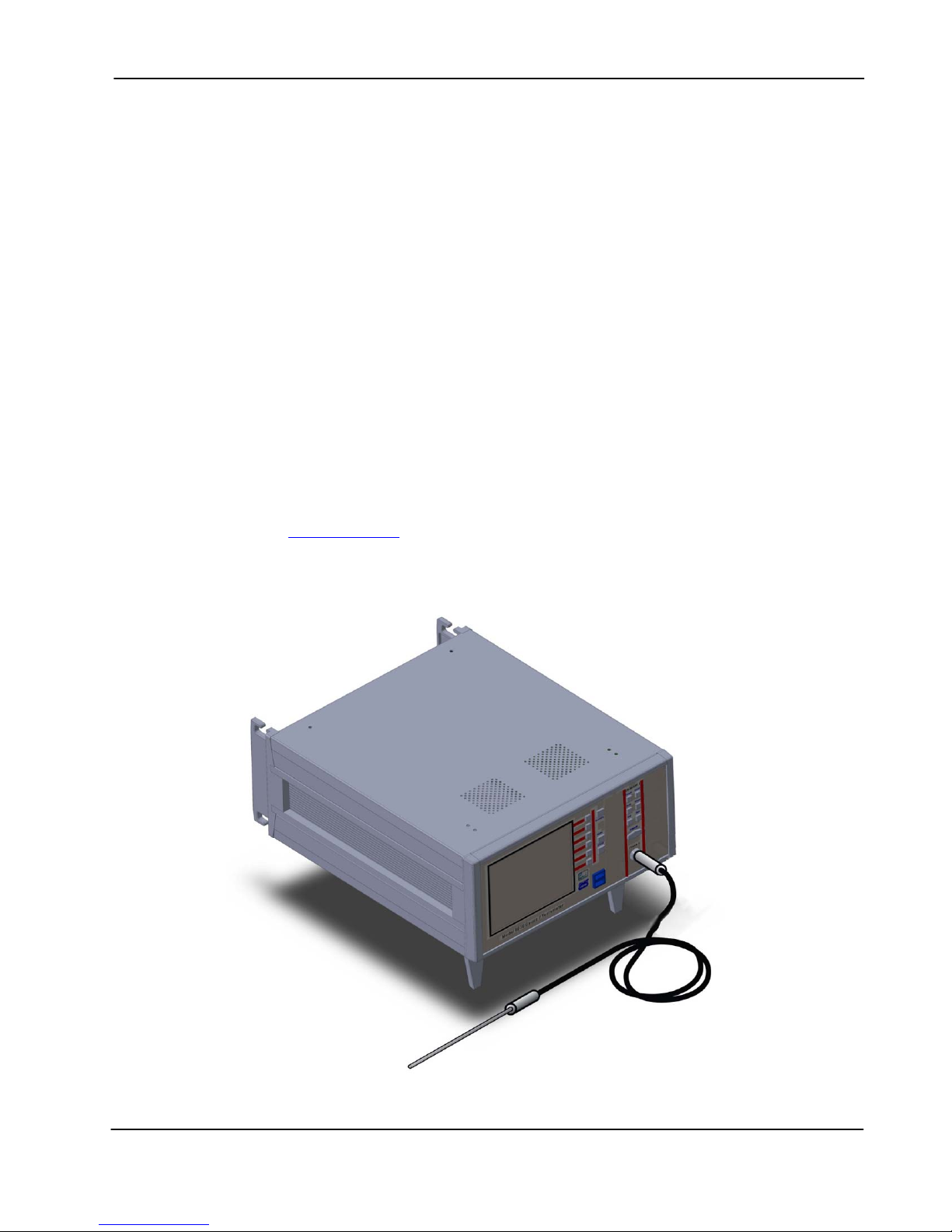
The F.W. BELL 8000 Series Gauss/Tesla meters incorporate the latest
developments in magnetic flux density measurement technology with a
modern user interface. It features a large display for easy viewing, a
comprehensive keypad for control of common functions, and an easy-touse menu system. The 8010 model features a single channel while the
8030 model provides three input channels. Both models provide high
accuracy suitable for use in the laboratory and enough features to be
versatile in a manufacturing environment.
Table 1-1 on the following page provides a list of features. Detailed
descriptions of the 8000 Series Meter functions and features are
provided in the remaining sections.
Note: Some features shown in this manual may be under development or are
not supported with the supplied system firmware. Visit the FW Bell web site at
www.fwbell.com
or contact customer support for the latest updates.
Section 1 – Introduction 1-1

F.W. BELL 8000 Series Gauss/Tesla Meter Instruction Manual
Table 1-1 8000 Series Gauss/Tesla Meter List of Features
Flux Density
Measurement
Display and User
Interface
Support
Functions
Auto Range and Zeroing Capability
DC and AC Field Measurement up to 50 kHz
Automatic Calibration
Units in gauss (G), tesla (T), amp/meter (A/m), or Oersted (Oe)
Large TFT color LCD Display with backlighting
AC Waveform Graphical Display Mode
Common Functions are Activated Quickly Through the Front Panel Keypad
Other Functions are Accessible Through Graphical Menu System
10 User Configuration Setups May be Stored
Analog and Digital Filtering
Relative Feature Allows Small Fluctuations to be Observed Within a Larger Field
Hold Feature Includes Arithmetic Min/Max Readings Calculated by the Instrument and
Signal Peaks/Valleys of Rapid Changing Pulses
Remote Operation
and
Communications
Signal Outputs
Probe Styles
Field Classifier With Pass/Fail Outputs
RS-232C Standard 9-pin female "D" connector
Protocol: SCPI-1999
Protocol: IEEE-488-1987.2 w/ External Prologix Adapter
Protocol: IEEE-802.3u Data Link Layer & TCP / IP Transport & Network Layer
Ethernet Standard RJ-45 Interface (10/100 MHz Ethernet Port)
Dual USB 2.0 Compliant Ports – Firmware Update via USB drive
Corrected and Uncorrected Analog Outputs
+/- 3V and +/- 10V Selectable Ranges
Either Waveform or RMS Signals
Vector Summation Output (Model 8030 Only)
Spare Analog Output(s) (presently not supported)
Transverse, Axial and 3-Axis
Temperature Compensation Available
Low, Medium, and High Field Options
Standard and Heavy Duty
Software &
Data Logging
Section 1 – Introduction 1-2
On-Site Firmware Updates
HTML User Remote Interface with Data Logging
Automatic Data Logging on USB Drive or Internal Memory
Screen Capture Utility

F.W. BELL 8000 Series Gauss/Tesla Meter Instruction Manual
General
Description
The Model 8000 Series Gauss/Tesla meters utilize Hall effect probes to
measure magnetic flux density in units of Gauss (G), Tesla (T), Amp/meter
(A/m), or Oersted (Oe). Either steady-state (DC) or alternating (AC) fields may
be measured. Fields as low as 10 µGauss (0.001 µT) or as high as 300k
Gauss (30 Tesla), at frequencies up to 50 kHz, can be measured with extreme
accuracy and 5-3/4 digit resolution. Each channel is calibrated and linearized
independently from data stored within the probes and meters. With a
temperature compensated Hall probe, the instrument can also compensate for
errors due to variations in probe temperature.
User Interface
The meters feature a WVGA, 600x480 pixel, TFT Color LCD Display with
backlighting. The display format may be customized by the operator and the
meter automatically adjusts text sizes for the most convenient view of the
information displayed.
Common functions are activated quickly through the front panel keypad, with
each channel having its own identical set of keys. In addition each key has a
back-light that is illuminated to indicate that it is active.
Less commonly used functions are easily accessible through the menu system.
Auto Range
Four measurement ranges may be selected manually or the instrument can
automatically select the best range based on the present flux density level being
measured.
Zero
The “zero” function allows the user to remove undesirable readings from nearby
magnetic fields (including earth’s) as well as to remove initial electrical offsets in
the probe and instrument. A “zero flux chamber” is included as an accessory
which shields the probe from external magnetic fields during this operation.
Hold
When the hold function is enabled the instrument will “hold” and display the
highest and/or lowest flux density readings that have been measured. Hold
features include capturing peaks and valleys of rapidly changing pulses as well
as arithmetically calculated max and min of slower changing signals.
Section 1 – Introduction 1-3

F.W. BELL 8000 Series Gauss/Tesla Meter Instruction Manual
General
Description
(Continued)
Relative
Another feature, called “relative mode”, allows large flux readings to be
suppressed so that small variations within the larger field can be observed
directly.
Update Interval
The update interval of the reading may be adjusted. Shorter update intervals
allow rapid fluctuations in flux density levels to be observed. Longer update
intervals provide higher resolution and stability in the flux density reading.
Analog Outputs
Each channel provides a Corrected and Uncorrected analog output voltage
signal available from standard BNC connectors. The uncorrected output signal
is representative of the magnetic flux density measured by the Hall probe. The
corrected output signal is compensated for influences of temperature and
frequency variations, as well as non-linearity inherent in the Hall probe and
instrument.
Both the Corrected and Uncorrected analog outputs offer the selection of either
raw waveform or RMS output data, and come with standard full scale output
ranges of 3V and 10V full scale. An adjustable full scale output up to 9.9V in
increments of 0.1V is also available (adjustable scale not supported).
Separate BNC outputs, not associated with the probe input channels, provide
analog outputs for the Vector Summation (8030 Only) and Auxiliary Analog
outputs (Auxiliary analog outputs not supported at this time).
These outputs may be connected to a voltmeter, oscilloscope, recorder, or
external analog-to-digital converter.
Analog Filters
Several analog filter modes are available in AC mode to help reject undesired
frequency content from AC field level signals. These filters affect both the
displayed reading and the analog outputs.
Field Classifiers
The “Classifier” function allows the user to define a lower and upper limit of flux
density that can be used to quickly determine the status of a magnetic field.
The instrument will indicate visually whether the field is below, within, or above
the pre-defined limits. The same information is provided in the form of general
purpose switch closures available at a standard 15 pin “D” type female
connector.
Section 1 – Introduction 1-4

F.W. BELL 8000 Series Gauss/Tesla Meter Instruction Manual
General
Description
(Continued)
Remote Operation
Remote operation is supported through either a standard 9-pin “D” RS232 serial
port connector or standard RJ-45 Ethernet connector (10/100 MHz Ethernet
Port). The 8000 meters can be remotely operated and flux density readings and
other information can be acquired by a remote computer or PLC. The
commands follow widely accepted protocols established by the SCPI-1999
standards.
In addition the 8000 Series Gaussmeters are supplied with an internal HTML
based remote monitoring and data logging application, that when connected to
a computer network can be accessed with standard web browser applications.
AC Waveform Display Mode
The graphical AC Waveform Display mode allows users to look at AC
measurements without the use of an external oscilloscope or other analog
graphing device. It provides operation and custom settings that will trigger on
user parameters and display the measurement on a familiar oscilloscope type
display.
Accessories
The instrument is shipped with a “zero flux chamber” used for shielding the
probe from unwanted fields during zeroing. In addition a sturdy carrying case is
provided for the zero flux chamber, probes, and other accessories or tools.
Section 1 – Introduction 1-5
F.W. BELL 8000 Series Gauss/Tesla Meter Instruction Manual
General
Description
(Continued)
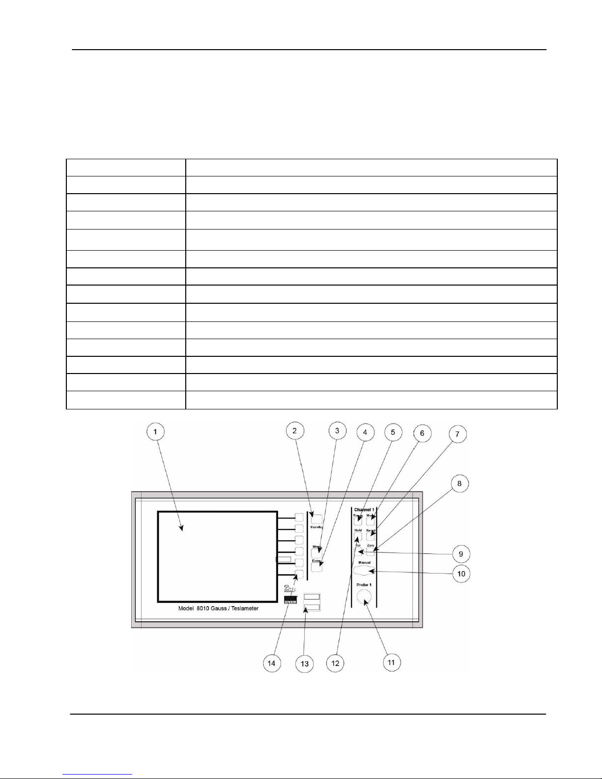
Table 1-2 Front Panel Description
(1) Display
Front Panel
The front panel consists of the TFT Color LCD display, Keypad, USB Ports,
and Probe Connector(s).
WVGA, 600 x 480 pixels, TFT Color LCD Display with Backlighting
(2) Standby Key
(3) Menu Key
(4) Enter Key
(5) Range Key
(6) Mode Key
(7) Reset Key
(8) Zero Key
(9) Relative Key
(10) Manual Key
(11) Probe Connector
(12) Hold Key
(13) USB Ports
(14) Menu Hot Keys
Standby Power Indicator
Menu System Navigation
Menu System Navigation
Selects Fixed Ranges or Auto Range
Selects ac or dc Field Measurement
Resets the Min/Max and Peak/Valley Detectors Used with the Hold Feature
Starts the Zeroing Process
Activates / De-activates the Relative Function
Numeric Entry / Menu Navigation
12 Pin Non-Magnetic Female Connector for Hall Effect Probes
Activates / Deactivates the Hold Feature
Dual USB 2.0 Compliant Ports
Menu Navigation and Function Selection
Figure 1-1 Front Panel (8010 Model Shown)
Section 1 – Introduction 1-6
F.W. BELL 8000 Series Gauss/Tesla Meter Instruction Manual
General
Description
(Continued)
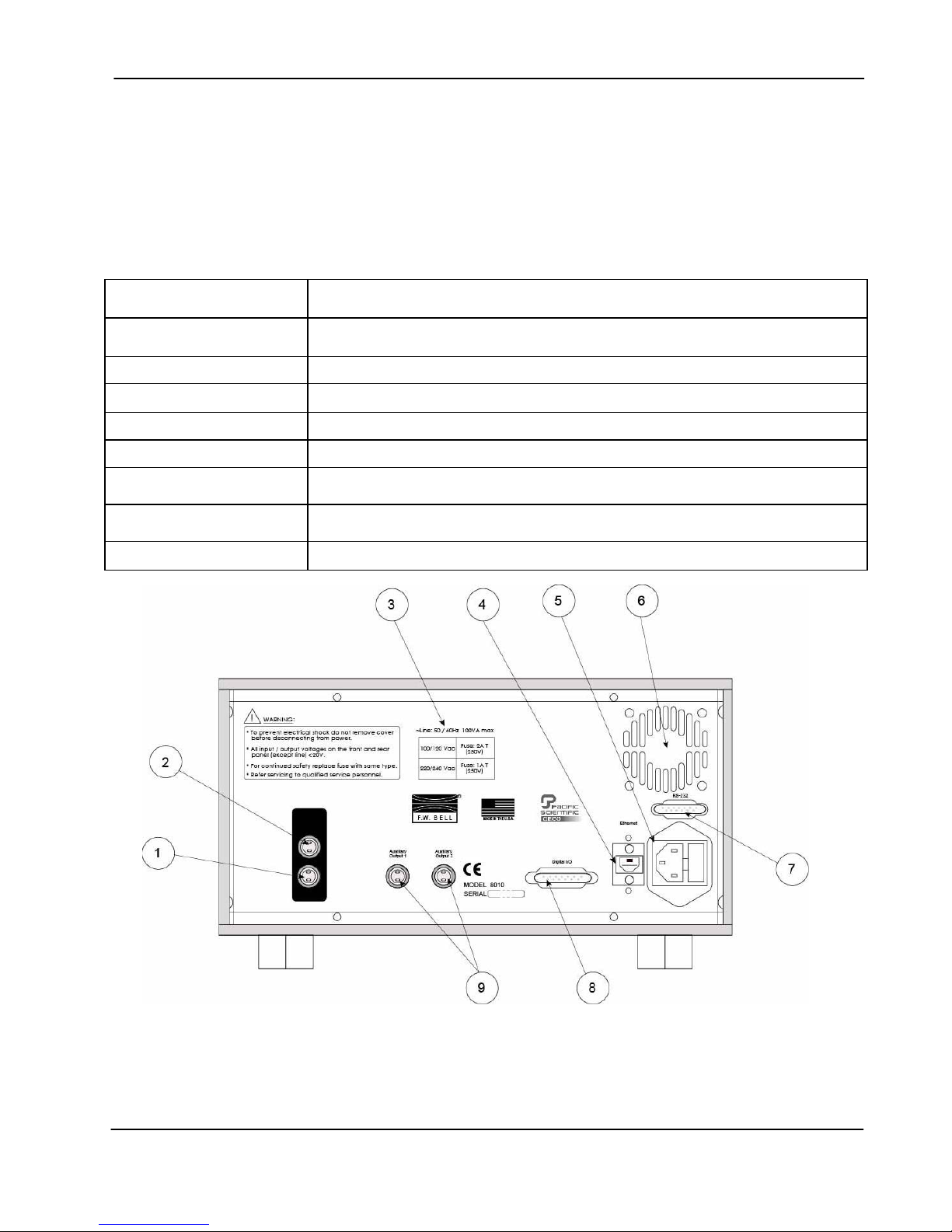
Table 1-3 Rear Panel Description
(1) Corrected Analog
Output
(2) Uncorrected Analog
Output
(3) Fuse Chart
Rear Panel
The rear panel consists of the Power Inlet / Fuse Holder, Analog Signal
Outputs, Communication Ports, and the Cooling Fan Vent.
Compensated Analog Output Voltage Signal, Standard BNC Connector.
Uncompensated Analog Output Voltage Signal, Standard BNC Connector.
Specifies the Proper Fuse Rating
(4) Ethernet Port
(5) Power Receptacle
(6) Cooling Vent
(7) RS-232 Port
(8) Digital I/O
(9) Auxiliary Output
Standard RJ-45 Connector (10/100 MHz Ethernet Port)
Accepts an International Instrumentation Power Line Cord
Vents for Cooling Fan (Should Remain Clear)
RS-232 Serial Communication Port. Standard 9 Pin “D” Type Female
Connector.
Standard 15 Pin “D” Type Female Connector, Provides Switch Closure Points
for Classifier Operation
Auxiliary Analog Voltage Output. Standard BNC Connector
Figure 1-2 Rear Panel (8010 Model Shown)
Section 1 – Introduction 1-7
F.W. BELL 8000 Series Gauss/Tesla Meter Instruction Manual
General
Description
(Continued)
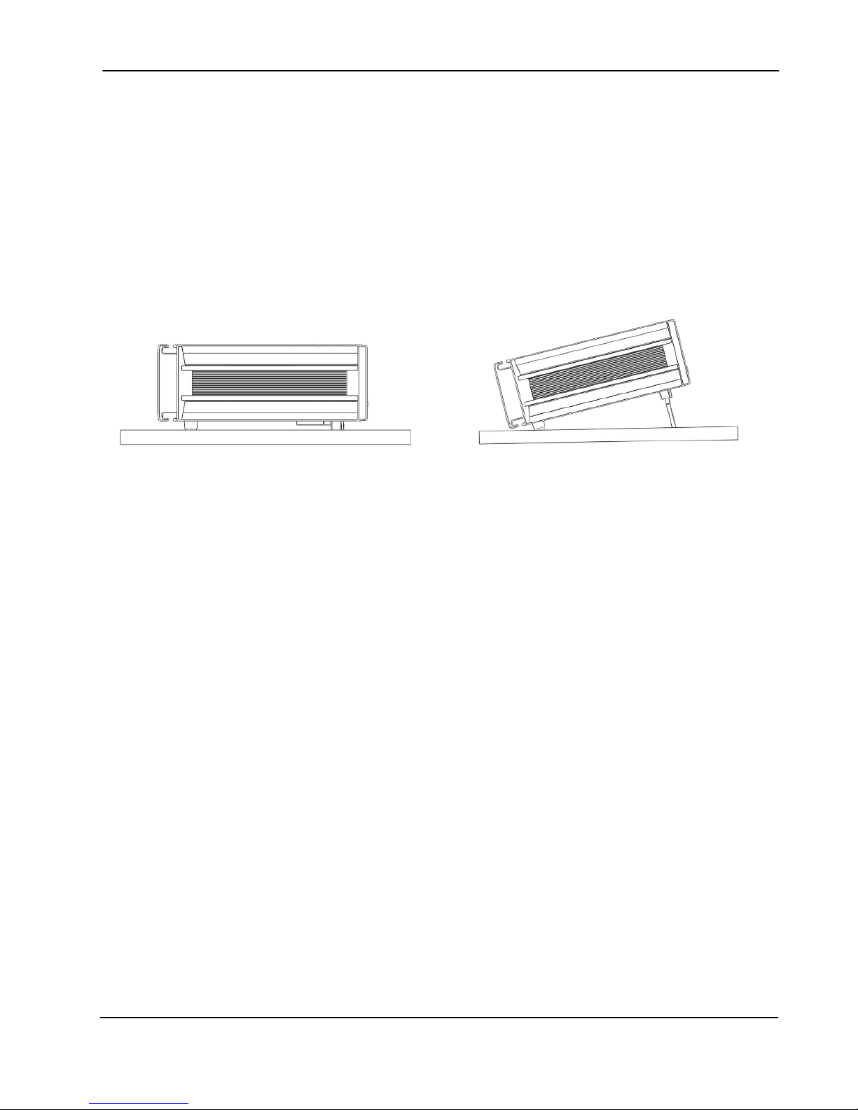
Cabinet
The cabinet is equipped with a side handle and two feet underneath the
unit which serve to adjust the tilt angle of the instrument.
Figure 1-3 shows the instrument in various positions.
A rack mount option (part number 418001) is available for the 8000
Series Meters that allows the meter to be mounted in a 19” equipment
rack. Consult your FW Bell sales representative for more information.
Applications
Figure 1-3 Various Positions of Meter
• Sorting or performing incoming inspection on permanent magnets,
particularly multi-pole magnets.
Testing audio speaker magnet assemblies, electric motor armatures
•
and stators, transformer lamination stacks, cut toroidal cores, coils
and solenoids.
Determining the location of stray fields around medical diagnostic
•
equipment.
Determining sources of electromagnetic interference.
•
Locating flaws in welded joints.
•
Inspection of ferrous materials.
•
• 3-dimensional field mapping.
• Inspection of magnetic recording heads.
•
Designing new magnetic assemblies.
Section 1 – Introduction 1-8
F.W. BELL 8000 Series Gauss/Tesla Meter Instruction Manual
µ
µ
SECTION 2 Specifications
Meter Specifications
Full-scale ranges are shown in the Tables 2-1 through 2-3 below, listed by probe type. In all
cases, the display resolution is 1 part in 300,000.
Table 2-1 Ranges for Low Field Probes
gauss (G) tesla (T) oersted (Oe) ampere-turn/meter (A/m)
300.000 mG
3.00000 G
Notes:
• Low Field MOX type probes have an upper calibrated range of
densities of
• MOS type probes have a measurement limit of
• Display resolution for MOS type probes is 10µG (1nT).
• Display resolution for MOX type probes is 1µG (0.1nT) but useful resolution is l imited to 5-10µG
(1nT) due to noise & drift.
±
30.0000
300.000
3G (300µT) with increased error.
T
T
Table 2-2 Ranges for Mid Field Probes (1x type)
gauss (G) tesla (T) oersted (Oe) ampere-turn/meter (A/m)
30.0000 G 3.00000 mT 30.0000 Oe 2.38732 kA/m
300.000 G 30.0000 mT 300.000 Oe 23.8732 kA/m
3.00000 kG 300.000 mT 3.00000 kOe 238.732 kA/m
30.0000 kG 3.00000 T 30.0000 kOe 2.38732 MA/m
Table 2-3 Ranges for High Field Probes (10x type)
gauss (G) tesla (T) oersted (Oe) ampere-turn/meter (A/m)
300.000 G 30.0000 mT 300.000 Oe 23.8732 kA/m
3.00000 kG 300.000 mT 3.00000 kOe 238.732 kA/m
30.0000 kG 3.00000 T 30.0000 kOe 2.38732 MA/m
300.000 kG 30.0000 T 300.000 kOe 23.8732 MA/m
300.000 mOe 23.8732 A/m
3.00000 Oe 238.732 A/m
±
2G but will respond to flux
±
1G (100µT) on a single range.
Section 2 - Specifications 2-1

F.W. BELL 8000 Series Gauss/Tesla Meter Instruction Manual
Min / Max Hold Acquisition Time:
dc Mode: 200mS
ac Mode: 200mS
Peak / Valley Hold Acquisition Time:
dc Mode: 6µs
ac Mode: varies depending on AC filters
2µs -- Full BW, No Correction & High
4µs – Medium
13µs – Low & Extra Low
Temperature Coefficient:
0.02% of reading
±1 count/degree Celsius
Update Rate:
Display: 5/sec (max)
Ethernet and RS-232 Output: 100/sec (max)
(refreshed up to 50/sec depending on mode,
AC filter settings, baud rate and
:MEAS:FLUX:FAST:RATE setting)
Corrected Analog Output Noise
(3V output range with 500 Hz filter):
All ranges:
2mVrms (35mV p-p)
Un-Corrected Analog Output Noise
(3V output range with 500 Hz filter):
300G, 3kG, 30kG ranges:
50µ Vrms (10mV p-p)
30G range:
2mVrms (20mV p-p)
NOTE: Un-corrected output polarity in AC mode
is inverted with respect to the Corrected Output
Analog Output Impedance:
<100 Ohms
Analog Output Connector:
Standard female BNC
Analog Output Scaling:
dc Mode: 3V or 10V standard
± 0.1V to ± 9.9V adjustable,
with increments of 0.1 V
ac Mode: 3Vrms or 10Vrms standard
± 0.1Vrms to ± 9.9Vrms adjustable,
with increments of 0.1Vrms
Front Panel Display:
WVGA, 600 x 480 pixels, TFT Color LCD Display
with Backlighting.
Dimensions: 4.7 W x 3.5 H inches
119 W x 89 H millimeters
Power:
Volts: 100/120 220/240
Frequency: 50-60 Hz or 50-60 Hz
Current: 1.0 A (max) 0.5 A (max)
Size:
11.5 W x 5.2 H x 14.5 D inches (5.85H with feet)
292 W x 132 H x 368 D millimeters (148.6H with feet)
Weight:
Net: 11.5 lbs. / 5.3 kg
Shipping: 17.7 lbs. / 8.1 kg
Warm-up Time to Rated Accuracy:
60 Minutes
Temperature Range:
Operating: 0 to 70 degrees Celsius
Storage: -20 to 60 degrees Celsius
Humidity Range:
0 to 35°C, to 80% RH at 35°C
Section 2 - Specifications 2-2

F.W. BELL 8000 Series Gauss/Tesla Meter Instruction Manual
Table 2-4 Accuracies at 23˚C ±2C˚ (Meter Only*)
DC Accuracy
Display and Digital
Outputs (min speed)
±0.05% of reading and
±0.01% of range
Corrected Analog Output and
Digital Outputs (max speed)
±0.15% of 3V or 10V ranges
Uncorrected Analog Output
(polarity is inverted in AC and
Wave Form mode)
3V range: 0.25% of
Reading ±40mV
10V range: 0.25% of
Reading ±120mV
AC Accur ac y
In DC Mode **
AC accuracy
in AC mode **
AC peak or
valley Accu ra c y
*Probes Errors Not Included
**See Table 6-2 regarding minimum AC signal requirements for rated accuracy.
Also refer to the end of Section 6; Sources of Measurement Error
N/A
2.0% of reading ±
0.15% of range (20 Hz
to 50 kHz)
5.00% of Reading N/A N/A
2% of range
DC to 100 Hz
2.0% of 3V or 10V ranges
(AC 20 to 500 Hz)
(AC RMS (DC) 20Hz-50kHz)
2% of range
DC to 100Hz
See Figure 2-1 for Graph
(Typical)
AC and AC RMS (DC) output
Uncorrect e d A nalog Out put Fr equency Response
for each A C Fil t er M ode (t ypi cal)
110%
100%
90%
80%
70%
60%
1-50k
20-50k
20-10k
20-500
1-500
50%
40%
1 10 100 1000 10000 100000
Figure 2-1 Frequency Response of Uncorrected Analog Output
(Meter only, not including probe response)
Section 2 - Specifications 2-3
Hz
F.W. BELL 8000 Series Gauss/Tesla Meter Instruction Manual
Communications
EMC Application Note
Use only high quality, double shielded cables for the RS-232 and Digital I/O connections. Keep the
length of the cables less than 3 meters. Cables greater than 3 meters with insufficient EMI shielding can
cause excessive emissions or may be susceptible to external interference.
Serial Port:
Format: RS-232C
Connector type: 9-pin “D” female
Cable length: 3 m (9.8 ft.) maximum
Receive input resistance:
Receive voltage limit:
Transmit output voltage:
Baud rate: 9600
Stop bits: 1, 2
Character length: 7,8
Parity: None
Handshaking None
Standards supported: SCPI-1999
3 kΩ minimum
± 30 V maximum
± 5 V min, ± 8 V typical
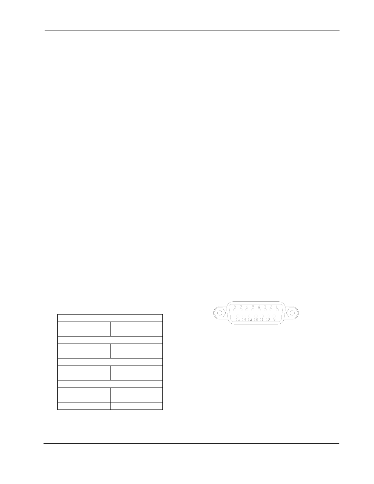
Classifier Digital Outputs:
Signal Type:
Connector: 15-Pin “D” Female
Switching Voltage:
Switching Current: 0.100 A DC or AC Peak MAX
On-State Resistance: 25 Ω MAX
Operating Time, Including
Solid State Relay Closure
30 V DC or AC Peak MAX
3 mS MAX
Bounce:
Table 2-5 Classifier Connections
Channel 1 Pins
Low
High
Channel 2 Pins
Low
High
Channel 3 Pins
Low
High
Common Pins
GND
+3.3Vdc
+5Vdc
1,9
2,10
3,11
4,12
5,13
6,14
8
7
15
Figure 2-2 Digital I/O Connector
Note: The +3.3Vdc, +5Vdc and GND pins are limited to
100mA maximum and intended for Classifier logic use only.
Note: The 8010 model uses Channel 2 Pins for classifier
operation. Channels 1 & 3 are used on the 8030 only.
15 Pin “D” Type
Section 2 - Specifications 2-4

F.W. BELL 8000 Series Gauss/Tesla Meter Instruction Manual
Regulatory Information
Compliance was demonstrated to the following specifications as listed in the official Journal of
the European Communities:
IEC 61000-4-3:2010 Radiated Electromagnetic Field (RF) Immunity
IEC 61000-4-4:2004 Electrical Fast Transient/Burst (EFT) Immunity (A1:2010)
IEC 61000-4-6:2008 Conducted Immunity
IEC 61000-4-8:2009 Magnetic Field Immunity
IEC 61000-4-11:2004 Voltage Interruptions
IEC 61000-4-11:2004 Voltage Dips
EN 61326-1:2006 Class A Emissions
CISPR 11:2009 (A1:2010) Radiated and Conducted Emissions
EN 61010-1:2010-06 Safety Requirements for Electrical Equipment for
Measurement, Control and Laboratory Use
Calibration
Service
EN 61326-1:2006 Immunity
IEC 61000-4-2:2008 Electrostatic Discharge (ESD) Immunity
EN 50581:2012 Reduction of the Use of Hazardous Substances
The instrument is calibrated at the factory prior to shipment. To maintain
rated accuracy, it is recommended that the instrument and any
accompanying probes be re-calibrated every 12 months. However, this is
only a recommendation and the calibration interval is determined by the
end user’s quality system, accuracy requirements or other needs.
Answers to any questions concerning the calibration of this instrument
may be obtained by contacting OECO at the address or website below:
OECO, LLC
4607 SE International Way
Milwaukie, OR 97222
Phone: 503-659-5999
www.fwbell.com
Section 2 - Specifications 2-5
F.W. BELL 8000 Series Gauss/Tesla Meter Instruction Manual
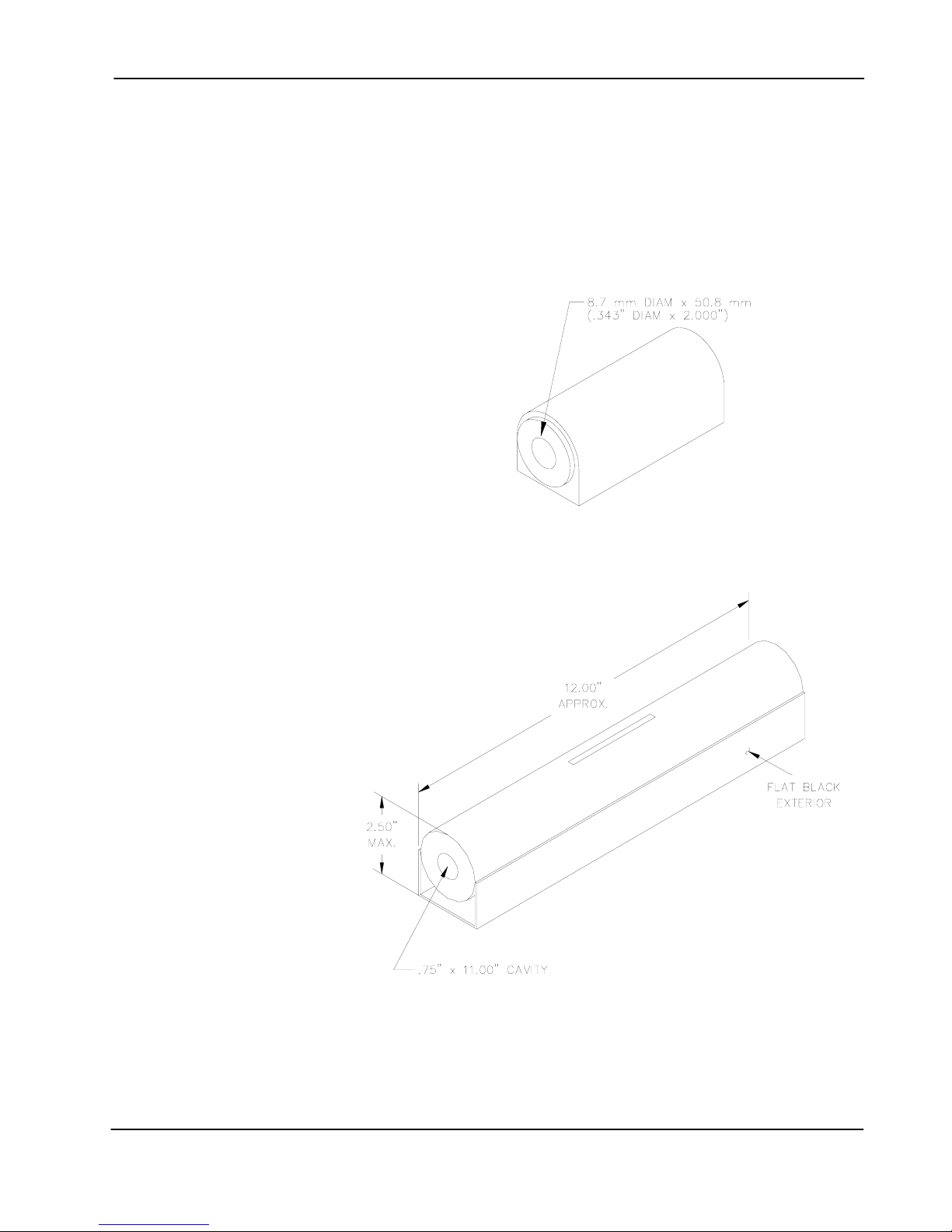
Zero Flux Chambers
Purpose:
To shield the probe from external magnetic fields during the ZERO or RELATIVE
operations.
Model Number:
YA-111
Cavity Dimensions:
Length: 50.8 mm (2”)
Diameter: 8.7 mm (0.343”)
Attenuation:
80 dB to 30 mT (300 G)
Model Number:
YA-112
Cavity Dimensions:
Length: 280 mm (11”)
Diameter: 12.7 mm (0.75”)
Attenuation:
60 dB to 30 mT (300 G)
Figure 2-3 YA-111 Zero Flux Chamber
Figure 2-4 YA-112 Zero Flux Chamber
Section 2 - Specifications 2-6

F.W. BELL 8000 Series Gauss/Tesla Meter Instruction Manual
SECTION 3 Probes
Overview
F.W. Bell’s 8000 series gauss/tesla meter probes are designed to meet
the electrical and mechanical requirements of virtually any application.
Models are available for transverse, axial, and very low field
measurements. The probe style is dependent upon the measurement
environment. The standard polypropylene or fiberglass stem is generally
adequate for laboratory or light handling environments, while the heavy
duty aluminum stem is recommended for harsher environments. The
probe’s length, outside diameter (axial probes) or thickness and width
(transverse probes) are important if there are physical constraints where
the probe will be used.
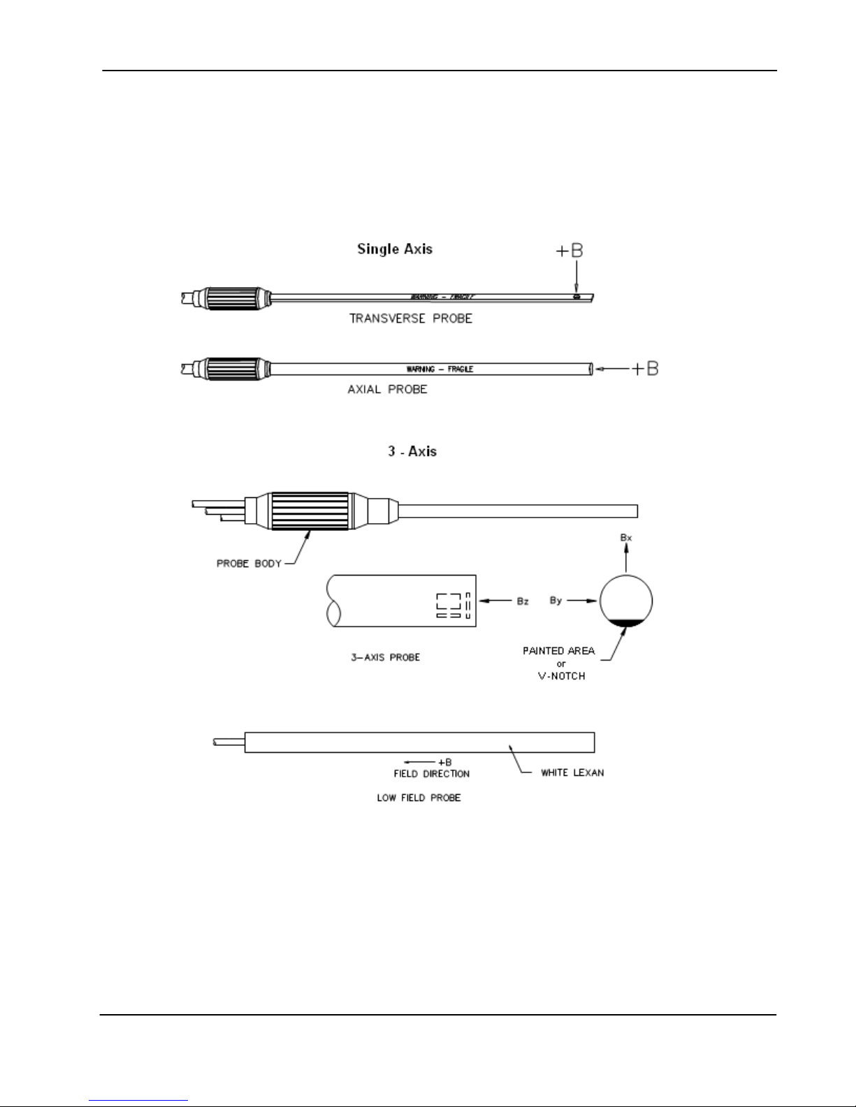
In “transverse” probes the Hall generator is mounted in a thin, flat stem
whereas in “axial” probes the Hall generator is mounted in a cylindrical
stem. The primary difference is the axis of measurement, as shown by
“+B” in Figure 3-2. Generally transverse probes are used to make
measurements between two magnetic poles such as those in audio
speakers, electric motors and imaging machines. Axial probes are often
used to measure the magnetic field along the axis of a coil or solenoid.
Either probe can be used where there are few physical space limitations,
such as in geomagnetic or electromagnetic interference surveys.
The low field probes are designed for high sensitivity, volumetric
measurement such as mapping variations in the earth’s magnetic field or
detecting the presence of ferrous objects.
Each probe is physically identified with model number, serial number and
a maximum voltage rating of “30VRMS / 60Vdc MAX” on a durable
polyester label wrapped around the cable jacket.
Handle Hall probes with care. Do not bend the stem or apply
pressure to the probe tip or drop the probe as damage may result.
Probe Extension Cables are available in several lengths as
Model XOVNK-xx, where xx is 05, 10, 15 or 20 feet. The 20 foot model
may present problems reading the probe memory in locations with higher
levels of electrical noise. The probe must be connected to the extension
before connecting extension to the gaussmeter.
Section 3 - Probes 3-1
F.W. BELL 8000 Series Gauss/Tesla Meter Instruction Manual
Probe
Variations
Table 3-1 Probe Maximum Field Levels and Resolutions
MOS Low Field 1G (100µT) 10µG (1nT)
MOX Low Field*
*Note: Low Field MOX probes have an upper calibrated range of ± 2G but will respond to ± 3G with
increased error. MOS probes have a measurement limit of
useful resolution of 10µG (1nT), but the least significant digit for the MOX type is not very stable.
A wide variety of probes are available for use with the 8000 gauss/tesla meters.
The types include heavy-duty transverse and axial, standard transverse and axial,
standard transverse with exposed element, flexible transverse and axial with
exposed element and low field probes. Most of these probes are available with or
without temperature compensation. All standard probes have a 10 foot (3.04m)
cable length and many are available with various stem lengths. Table 3-1 lists the
maximum field measurement capabilities and resolutions.
Probe Type
Medium Field 30 kG (3 T)
High Field 300 kG (30 T)
Maximum Field Display Resolution
3 G (300 µT) 1 µG (0.1 nT)
0.1 mG (0.01 µT)
1 mG (0.1 µT)
±
1G. Both Low Field types have a
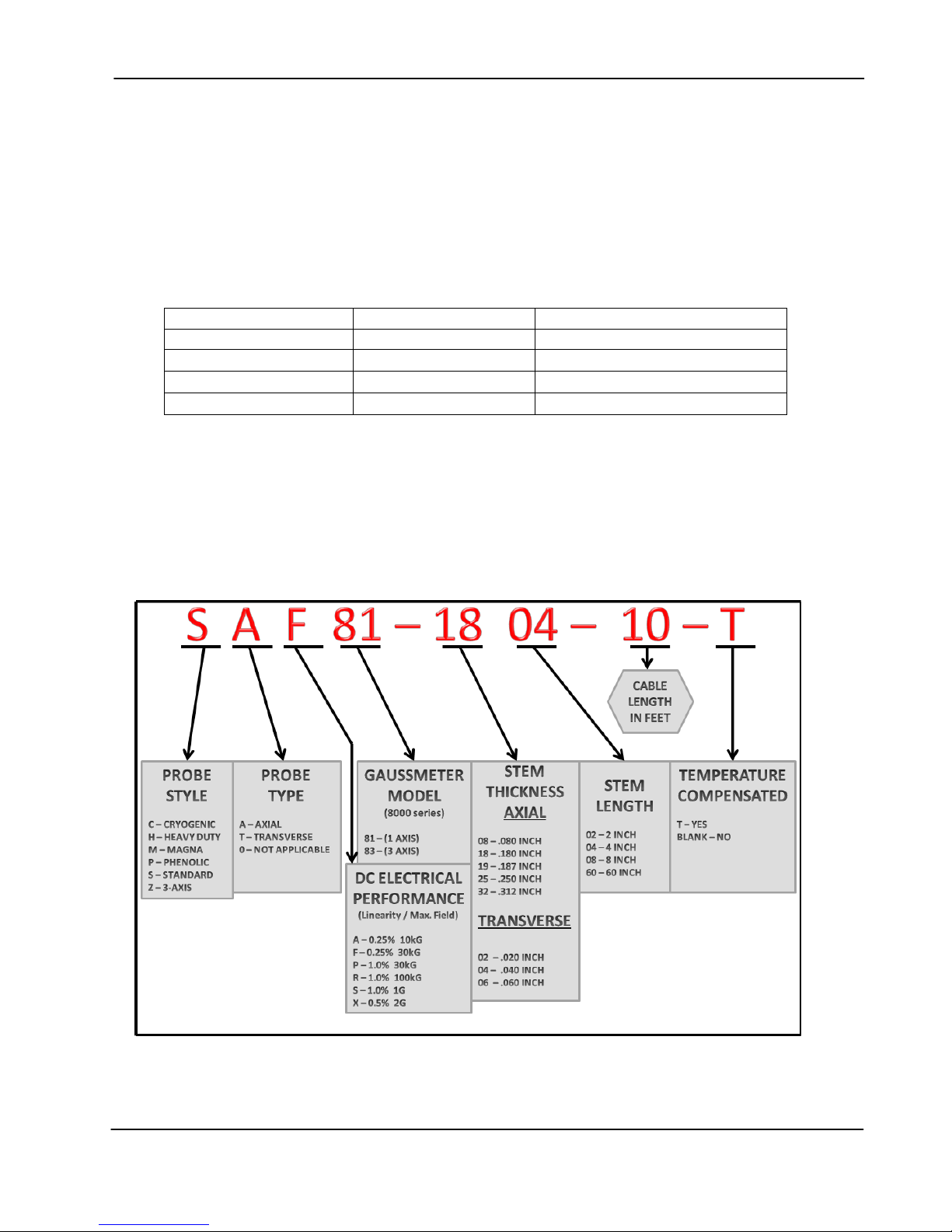
Figure 3-1 serves as model number guide for F.W. BELL 8000 series probes.
Full electrical and mechanical specifications of probes are available on
request.
Figure 3-1 8000 Series Probe Model Chart Example
Note: Probes are not available in all part number combinations.
Section 3 - Probes 3-2

F.W. BELL 8000 Series Gauss/Tesla Meter Instruction Manual
Probe
Memory
The connector of each probe contains a memory device which stores
registration information (model number, serial number, date calibrated, etc.)
as well as performance information for Hall generator sensitivity, linearity,
frequency response and temperature response.
Probe Stem
Temperature
Effects
Fixturing
Most probes except the low field probe are supplied with a rigid stem cover to
help protect the probe when not in use. It is strongly recommended to use the
stem protector when storing the probe or when the probe will not be used for
any length of time. If a probe stem becomes damaged it cannot be repaired.
All Hall probes have an initial electrical offset that will affect the accuracy of
static (dc) field measurements. This offset should be canceled using the
instrument’s “zero” function. However, the probe’s offset and sensitivity will
change with temperature. Using temperature-compensated probes can
minimize these effects if the probe is operated over a temperature range
outside of 23 ±3°C.
There can be substantial errors in uncompensated probes. A typical probe’s
dc offset can change by ± 0.1 G / °C (±10 µT / °C). It is best to allow the
probe’s temperature to stabilize before performing a “zeroing” operation.
Zeroing is discussed in Section 6 – Flux Density Measurement. The
probe’s sensitivity will decrease as temperature increases. Probes are
calibrated at ambient temperature (~23 °C). A typical probe may change by
–0.05% / °C. For instance a reading of 200 mT at 23°C may drop to 197 mT
at 50°C.
In some applications it may be necessary to install a probe into a holding
fixture to maintain a constant probe position. If this becomes necessary, do
not clamp onto the probe stem as this will most likely damage the probe.
Rather, clamp onto the aluminum or plastic probe body or “handle”.
Section 3 - Probes 3-3
F.W. BELL 8000 Series Gauss/Tesla Meter Instruction Manual
8000 Series Probes
Figure 3-2 Hall Probe Configurations
Section 3 - Probes 3-4

F.W. BELL 8000 Series Gauss/Tesla Meter Instruction Manual
SECTION 4 Setup
Safety Instructions
GENERAL:
For safe and correct use of this instrument it is necessary that both
operating and servicing personnel follow generally accepted safety
procedures plus the safety cautions and warnings specified.
If it is determined that safety protection has been impaired, the
instrument must be made inoperative and be secured against any
unintended operation. For example, safety may be impaired if the
instrument fails to perform or shows visible damage.
CAUTION:
All input and output voltages, except line (mains), are less than 20V.
WARNING:
The opening of covers or removal of parts might expose live parts
and accessible terminals which can be dangerous.
WARNING:
Any interruption of protective earth conductors or disconnection of
the protective earth terminals inside or outside of the instrument can
create a dangerous condition.
CAUTION:
For continued protection replace the fuse with the same type (IEC
127 type T).
Section 4 - Setup 4-1
 Loading...