

F.W. Bell 7030 Instruction Manual
7030 GAUSS/TESLA METER
Instruction
Manual

F.W. BELL Model 7030 Gauss/Tesla Meter Instruction Manual
THIS SIDE BLANK !
(Inside of Front Cover)

Instruction Manual
Manual UN-01-251
Item 359936
Rev. E, ECO 14211
All Rights Reserved.
MODEL 7030
GAUSS / TESLA METER
F.W. BELL Model 7030 Gauss/Tesla Meter Instruction Manual
This symbol appears on the instrument and probe. It refers the operator
to additional information contained in this instruction manual, also
identified by the same symbol.
NOTICE:
See Pages 4-1, 4-2, and 4-3
for SAFETY
instructions prior to first use !
See Page 2-4
for EMC Notes concerning I/O Cables and I/O
Filter Adapters

F.W. BELL Model 7030 Gauss/Tesla Meter Instruction Manual
Table of Contents
Section – 1 Introduction
Overview…………………………………………………………………………………….………..
General Description………………………………………………………………………………….
Applications…………………………………………………………………………………..…….…
Section – 2 Specifications
Instrument……………………………………………………………………………………………..
Calibration Service……………………………………………………………………………………
Zero Flux Chamber…………………………………………………………………………………..
Section – 3 Probes
Overview………………………………………………………………………………………...…….
Probe Variations………………………………………………………………………………….….
Probe Memory……………………………………………………………………………………...…
Probe Stem…………………………………………………………………………………..………..
Temperature Effects…………………………………………………………………………..……..
Fixturing……………………………………………………………………………………………….
1-1
1-3
1-8
2-1
2-6
2-7
3-1
3-2
3-3
3-3
3-3
3-3
Section – 4 Setup
Safety…………………………………………………………………………………………………
Line Voltage Settings / Fuse Panel…………………………………………………………………
Adjusting the Handle…………………………………………………………………………………
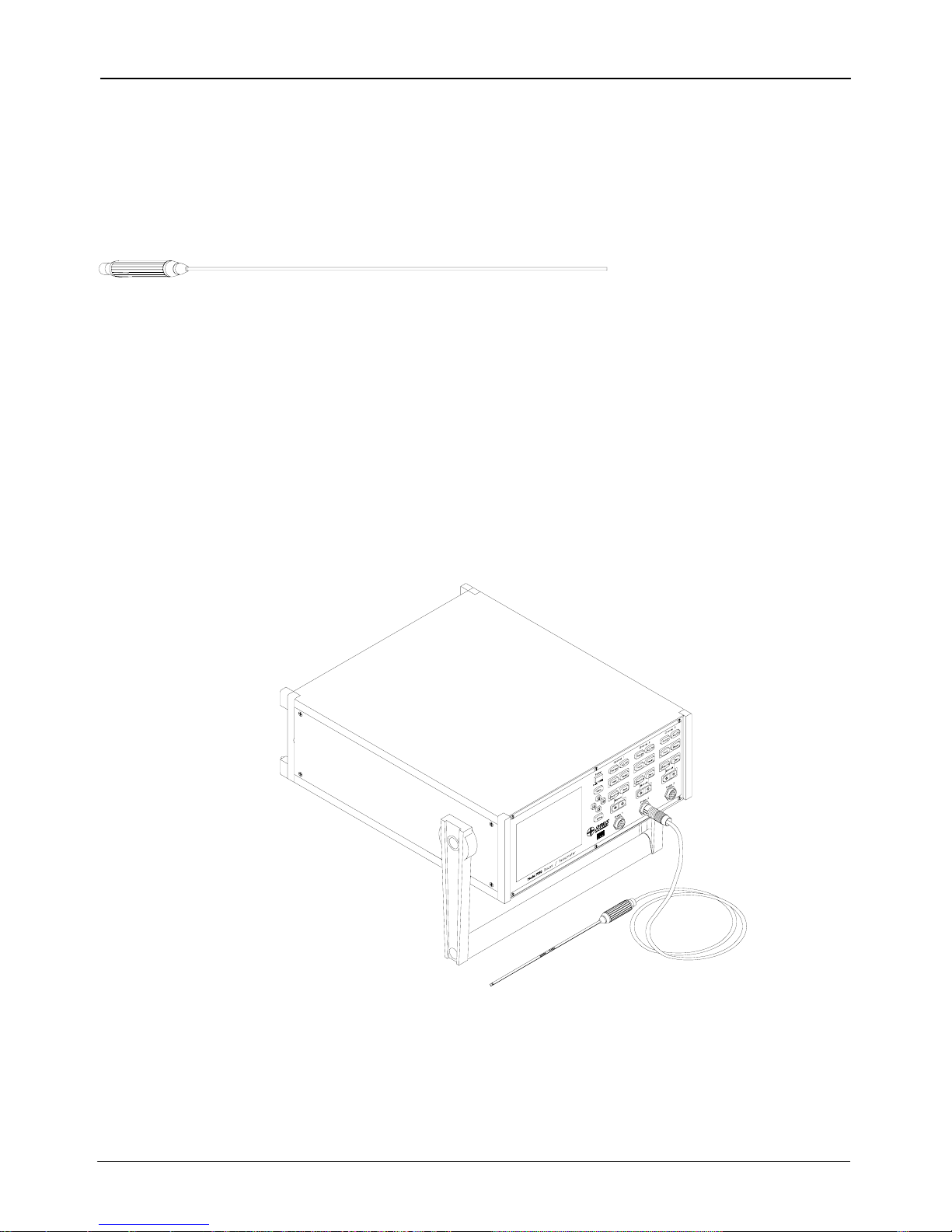
Probe Installation……………………………………………………………………………………..
Power Up………………………………………………………………………………………………
Section – 5 User Interface
Overview………………………………………………………………………………………………
Front Panel Key Pad…………………………………………………………………………………
Menu System………………………………………………………………………………………….
Using the Mouse……………………………………………………………………………………..
Help System…………………………………………………………………………………………..
System Menu………………………………………………………………… ………… … ………..
Setup Save-Load……………………………………………………………………………………..
Display Format………………………………………………………………………………………..
Setting the Date and Time………………………………………………………………….
4-1
4-3
4-4
4-5
4-6
5-1
5-2
5-3
5-5
5-6
5-6
5-7
5-9
5-11
i

F.W. BELL Model 7030 Gauss/Tesla Meter Instruction Manual
Section – 6 Flux Density Measurement
Overview……………………………………………………………………………………………
Measurement Units and Selection………………………………………………………………
Present Flux Density Reading……………………………………………………..…….………
Measurement Mode Indicator……………………………………………………………………
Range Selection………………………………….………………………………………………
ac or dc Measurement Selection……………………………………………………………….
ac Mode Operation………………………………………………………………………………
ac Mode Analog Filtering…………………………………………………………………………
dc Mode Operation………………………………………………………………………………
Zeroing………..……………………………………………………………………………………..
Update Interval……………………………………………………………………………………
Hold Function……………………………………………………………………………………….
Relative Mode…………………………………………………………………………………..…
Vector Summation…………………………………………………………………………………
Analog Outputs…………………………………………………………………………………….
Classifiers………………………………………………………………………………………..
Sources of Measurement Errors…………………………………………………………………
Section – 7 Remote Operation
Introduction……………………………………………………………………………………………
IEEE 488 Functional Description……………………………………………………………………
RS-232 Functional Description……………………………………………………………………...
Communications Setup…………………………………………………………………………….
IEEE 488 General Bus Commands………………………………………………………………...
Error Queue and Output Queue…………………………………………………………………….
Status…………..………………………………………………………………………………………
Status Byte and Service Request…………………………………………………………………..
Standard Event Register…………………………………………………………………………….
Measurement Event Register………………………………………………………………….….
Operation Event Register…………………………………………………………………….……
Questionable Event Register……………..…………………………………………………….…
IEEE 488.2 “Common” Command Syntax……………………………………………….………
IEEE 488.2 “Common” Commands………………………………………………………………
SCPI Command Syntax……………………………………………………………………………
SCPI Commands – General………………………………………………………………………
SCPI Commands – Error Queue Messages and Commands…………………………………
SCPI Commands – System Information and Configuration Commands……………………
SCPI Commands – Status Commands…………………………………………………………
6-1
6-2
6-3
6-3
6-4
6-5
6-5
6-7
6-7
6-8
6-10
6-11
6-13
6-16
6-19
6-21
6-23
7-1
7-2
7-3
7-5
7-6
7-7
7-7
7-9
7-11
7-12
7-13
7-13
7-14
7-15
7-18
7-19
7-23
7-23
7-26
ii

F.W. BELL Model 7030 Gauss/Tesla Meter Instruction Manual
SCPI Commands – Unit Commands…………………………………………………………
SCPI Commands – Range Commands…………………………………………………….……
SCPI Commands – Filter Commands……………………………………………………………
SCPI Commands – Averaging Commands……………………………………………………
SCPI Commands – Classifier (Limit) Commands………………………………………………
SCPI Commands – Zeroing Commands………………………………………………………
SCPI Commands – Relative Offset Commands………………………………………………
SCPI Commands – Analog Output Commands……………………………………………….
SCPI Commands – Vector Summation Commands……………………………………………
SCPI Commands – Hold Commands…………….………………………………………………
SCPI Commands – Measurement Commands……………………………………………….
Intermixing “Common” and SCPI Commands………………………………………………
Message Terminators……………………………………………………………………………
Example Using the Event, Enable, and Condition Registers…………………………………
Appendix A
Appendix B
Warranty
Understanding Flux Density…………………………………………………
Vector Summation Tutorial………………………………………………….
7-27
7-28
7-29
7-30
7-30
7-32
7-32
7-34
7-37
7-37
7-39
7-41
7-41
7-42
A-1
B-1
List of Tables
Table 1-1 Model 7030 gauss/tesla meter List of Features……………………….…….. 1-2
Table 1-2 Front Panel Description…………………………………………………..…….. 1-6
Table 1-3 Rear Panel Description…………………………………………………..……... 1-7
Table 2-1 Probe Ranges…………………………………………………………….…..….. 2-1
Table 2-2 Accuracies (Instrument Only)……………………………………………..……. 2-2
Table 3-1 Probe Maximum Field Levels and Resolutions…………………………..…... 3-2
Table 5-1 Default Configuration Settings…………………………………….…….……... 5-8
Table 5-2 Display Options…………………………………………………………..…….… 5-9
Table 6-1 Available Units………………………………………………….……………..…. 6-2
Table 6-2 Minimum Magnitudes for Rated ac Accuracy……………………..…….…… 6-6
Table 6-3 Autofilter Switch Points………………………………………………..…...……. 6-7
Table 6-4 Number of Samples for Update Interval Settings…………………………….. 6-10
Table 7-1 RS-232 Available Settings………………………………………………………. 7-5
Table 7-2 General Command Summary for IEEE 488…………………………………… 7-6
Table 7-3 Common Command Summary……………………………………………...….. 7-15
Table 7-4 SCPI Commands……………………………………………………...…………. 7-19
Table 7-5 12 Hour to 24 Hour Conversion Table…………………………………………. 7-24
Table 7-6 Operating Ranges with Various Probes…………………………………...…... 7-28
iii

F.W. BELL Model 7030 Gauss/Tesla Meter Instruction Manual
List of Illustrations
Figure 1-1
Figure 1-2
Figure 1-3
Figure 2-1
Figure 2-2
Figure 2-3
Figure 3-1
Figure 3-2
Figure 4-1
Figure 4-2
Figure 4-3
Figure 4-4
Figure 4-5
Figure 4-6
Figure 5-1
Figure 5-2
Figure 5-3
Figure 5-4
Figure 6-1
Figure 6-2
Figure 6-3
Figure 6-4
Figure 6-5
Figure 6-6
Figure 6-7
Figure 6-8
Figure 6-9
Figure 6-10
Figure 7-1
Figure 7-2
Figure 7-3
Figure 7-4
Figure 7-5
Figure 7-6
Figure 7-7
Figure 7-8
Figure A-1
Figure A-2
Figure B-1
Figure B-2
Figure B-3
Figure B-4
Front Panel………………………………………………………………………..
Rear Panel…………………………………………………………………….…..
Various Positions of Instrument…………………………………………………
Frequency Response of Uncorrected Analog Outputs (%Deviation)……….
Digital I/O Connector……….…………………………………………………….
Zero Flux Chamber……………………………………………………………….
7000 Series Probe Ordering Guide……………………………………………..
Hall Probe Configurations………………………………………………….…….
Probe Electrical Warning………………………………………………….……..
Fuse Panel……………………………………………………………………..….
Adjusting the Handle………………………………………………………….….
Installing and Removing Probes…………………………………………….…..
Power Switch Positions…………………………………………………………..
Boot Up Screen…………………………………………………………………...
Front Panel Keys………………………………………………………………….
Menu Items………………………………………………………………………..
Using Selections………………………………………………………………….
Main Menu………………………………………………………………………..
Present Flux Density Reading…………………………………………………..
Measurement Mode Indicator…………………………………………………...
Frequency / Filter Indicator………………………………………………………
Indeterminate Frequency Indicator…………………………………………….
Relative Value Indicator…………………………………………………………
7000 Series 3-Axis Probe Orientation…………………………………………
Example Circuit for Classifier Outputs…………………………………………
Probe Output Versus Flux Angle……………………………………………….
Probe Output Versus Distance………………………………………………….
Flux Density Variations in a Magnet……………………………………………
IEEE-488 Connector…………………………………………………………….
RS-232 Connector……………………………………………………………….
Condition, Event, and Enable Registers……………………………………….
Status Byte and SRQ Enable Registers………………………………………
Standard Event Register………………………………………………………..
Measurement Event Register…………………………………………………..
Operation Event Register………………………………………………………..
Questionable Event Register……………………………………………………
Flux Lines of a Permanent Magnet……………………………………………..
Hall Effect Sensor……………………………………………………………...…
Two Dimensional Co-ordinate System…………………………………………
Vector Angle in a Two Dimensional System…………………………………..
Three-dimensional Co-ordinate System………………………………………..
Vector Angles in a Three-dimensional System………………………………..
1-6
1-7
1-8
2-3
2-4
2-6
3-2
3-4
4-2
4-3
4-4
4-5
4-6
4-7
5-2
5-3
5-4
5-4
6-3
6-3
6-5
6-6
6-14
6-16
6-22
6-23
6-24
6-24
7-2
7-4
7-8
7-9
7-11
7-12
7-13
7-13
A-1
A-2
B-1
B-2
B-3
B-3
iv
F.W. BELL Model 7030 Gauss/Tesla Meter Instruction Manual
Section 1 Introduction
OVERVIEW
The F.W. BELL model 7030 gauss/tesla meter incorporates the latest
developments in magnetic flux density measurement technology with a
modern user interface. It features a large display for easy viewing, a
comprehensive keypad for control of common functions, and an easy-to-use
menu system. The model 7030 features three independent channels, with
high accuracy suitable for use in the laboratory, and enough features to be
versatile in a manufacturing environment. Table 1-1 on the following page
provides a list of features.
A detailed description of the 7030’s functions and features is provided in the
remaining sections.
F.W. BELL 7030 GAUSS/TESLA METER
Section 1 - Introduction 1-1
F.W. BELL Model 7030 Gauss/Tesla Meter Instruction Manual
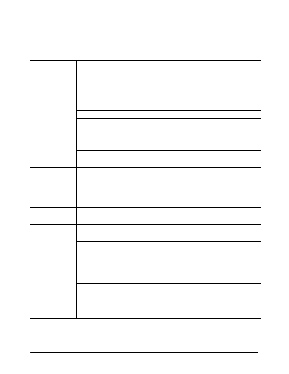
Table 1-1 Model 7030 gauss/tesla meter List of Features
Flux Density
Measurement
User Interface
Support
Functions
Auto Range and Zeroing Capability
dc and ac Field Measurement up to 50 kHz
Automatic Calibration
Units in gauss (G), tesla (T), amp/meter (A/m), or oersted (Oe)
Temperature Compensated Hall Probes Available
Large ¼ VGA Multi-shade Amber Display
Display Arrangement is Configurable by the User
Each Channel’s Common Functions are Activated Quickly Through the Front Panel
Keypad
Other Functions are Accessible Through Graphical Menu System
Comprehensive Help System
Up to Four Configuration Setups May be Stored
Mouse Supported ( Optional )
Analog and Digital Filtering
Relative Feature Allows Small Fluctuations to be Observed Within a Larger Field
Hold Feature Includes Arithmetic Min/Max Readings Calculated by the Instrument and
Signal Peaks/Valleys of Rapid Changing Pulses
Remote Operation
Signal Outputs
Probe Styles
Software
Field Classifiers With Pass/Fail Outputs
IEEE 488.2 (GPIB) Interface
RS-232C Serial Port Interface
Each Channel Has a Corrected and Uncorrected Analog Output
Corrected Outputs Provide up to 50k samples/sec
3V, 10V, and 0-10V Adjustable Full Scale Range Settings
Either Raw or RMS Signals
Vector Summation Output
Transverse, Axial, and 3-Axis
Temperature Compensated
Low, Medium, and High Field
Standard and Heavy Duty
LabView Drivers Available
On-Site Firmware Updates
1-2 Section 1 - Introduction

F.W. BELL Model 7030 Gauss/Tesla Meter Instruction Manual
GENERAL
DESCRIPTION
The Model 7030 gauss/tesla meter is a three channel bench-top
instrument that utilizes Hall effect probes to measure magnetic flux
density in units of gauss (G), tesla (T), amp/meter (A/m), or oersted
(Oe). Either steady-state (dc) or alternating (ac) fields may be
measured. Fields as low as 10 µGauss (0.001 µT) or as high as 300k
gauss (30 tesla), at frequencies up to 50 kHz, can be measured with
extreme accuracy and 5-3/4 digit resolution. Each channel is
calibrated and linearized independently from data stored within its
probe. With a temperature compensated Hall probe, the instrument
can compensate for errors due to temperature variations.
User Interface
The instrument features a ¼ VGA multi-shade amber graphics
display. The display format and orientation may be customized by the
operator. The instrument automatically adjusts text sizes for the most
convenient view for a given amount of information being displayed.
Common functions are activated quickly through the front panel
keypad, with each channel having its own identical set of keys. Each
key has a back-light that is illuminated to indicate that it is active.
Less commonly used functions are easily accessible through the
menu system. The instrument also features a comprehensive help
system. As an option, the 7000 series supports the use of a standard
Microsoft® compatible serial mouse.
Up to four configuration setups may be saved and recalled.
Note: Each channel operates independently and each has the
following features.
Auto Range
Four measurement ranges may be selected manually or the
instrument can automatically select the best range based on the
present flux density level being measured.
Section 1 - Introduction 1-3

F.W. BELL Model 7030 Gauss/Tesla Meter Instruction Manual
GENERAL
DESCRIPTION
(Continued)
Zero
The “zero” function allows the user to remove undesirable readings
from nearby magnetic fields (including earth’s) as well as to remove
initial electrical offsets in the probe and instrument. A “zero flux
chamber” is included as an accessory which shields the probe from
external magnetic fields during this operation. Channels may be
zeroed independently or all at once.
Hold
When the hold function is enabled the instrument will “hold” and
display the highest and/or lowest flux density readings that have been
measured. Hold features include capturing peaks and valleys of rapid
changing pulses as well as arithmetically calculated max and min of
slow changing signals.
Relative
Another feature, called “relative mode”, allows large flux readings to be
suppressed so that small variations within the larger field can be
observed directly.
Update Interval
The update interval of the reading may be adjusted. Shorter update
intervals allow rapid fluctuations in flux density levels to be observed.
Longer update intervals provide higher resolution and stability in the
flux density reading.
Analog Output
Each channel provides a corrected and uncorrected analog output
voltage signal available from standard BNC connectors. The
uncorrected output signal is representative of the magnetic flux density
measured by the Hall probe. The corrected output signal is
compensated for influences of temperature and frequency variations,
as well as non-linearities inherent in the Hall probes and instrument.
The corrected output is specified with a higher accuracy than the
uncorrected output, with a bandwidth up to 200 Hz. The uncorrected
output is less accurate, but has a bandwidth up to 50kHz.
1-4 Section 1 - Introduction

F.W. BELL Model 7030 Gauss/Tesla Meter Instruction Manual
GENERAL
DESCRIPTION
(Continued)
A separate BNC connector, labeled “Vector Summation”, provides a
corrected output signal that is proportional to the resultant magnitude
of the three channels vector sum.
Standard full scale output ranges are 3V, 10V, 3V
adjustable full scale up to 9.9V or 9.9V
in increments of 0.1V, is
RMS,
, and 10V
RMS
RMS.
An
also available. These outputs may be connected to a voltmeter,
oscilloscope, recorder, or external analog-to-digital converter.
Analog Filters
A low pass filter is available for each channel that may be set to pass
frequencies only below 50kHz, 5kHz, or 500Hz. The instrument can
automatically select the best filter setting based on the present flux
density being measured. The filters affect both the displayed reading
and the analog outputs.
Field Classifiers
The “Classifier” function allows the user to define a lower and upper
limit of flux density that can be used to quickly determine the status of
a magnetic field. The instrument will indicate visually whether the
field is below, within, or above the pre-defined limits. The same
information is provided in the form of general purpose switch closures
available at a standard 15 pin “D” type female connector.
Remote Operation
Remote operation is supported through a standard 9-pin “D” RS232
serial port connector or through an IEEE-488.2 (GPIB)
instrumentation bus. The 7030 can be fully configured and flux
density readings and other information can be acquired by a remote
computer or PLC. The commands follow widely accepted protocols
established by the IEEE-488.2 and SCPI-1999 standards.
Accessories
The instrument is shipped with a “zero flux chamber” used for
shielding the probes from unwanted fields during zeroing. A sturdy
carrying case is provided for the zero flux chamber, probes, and this
manual.
Section 1 - Introduction 1-5
F.W. BELL Model 7030 Gauss/Tesla Meter Instruction Manual
GENERAL
DESCRIPTION
(Continued)
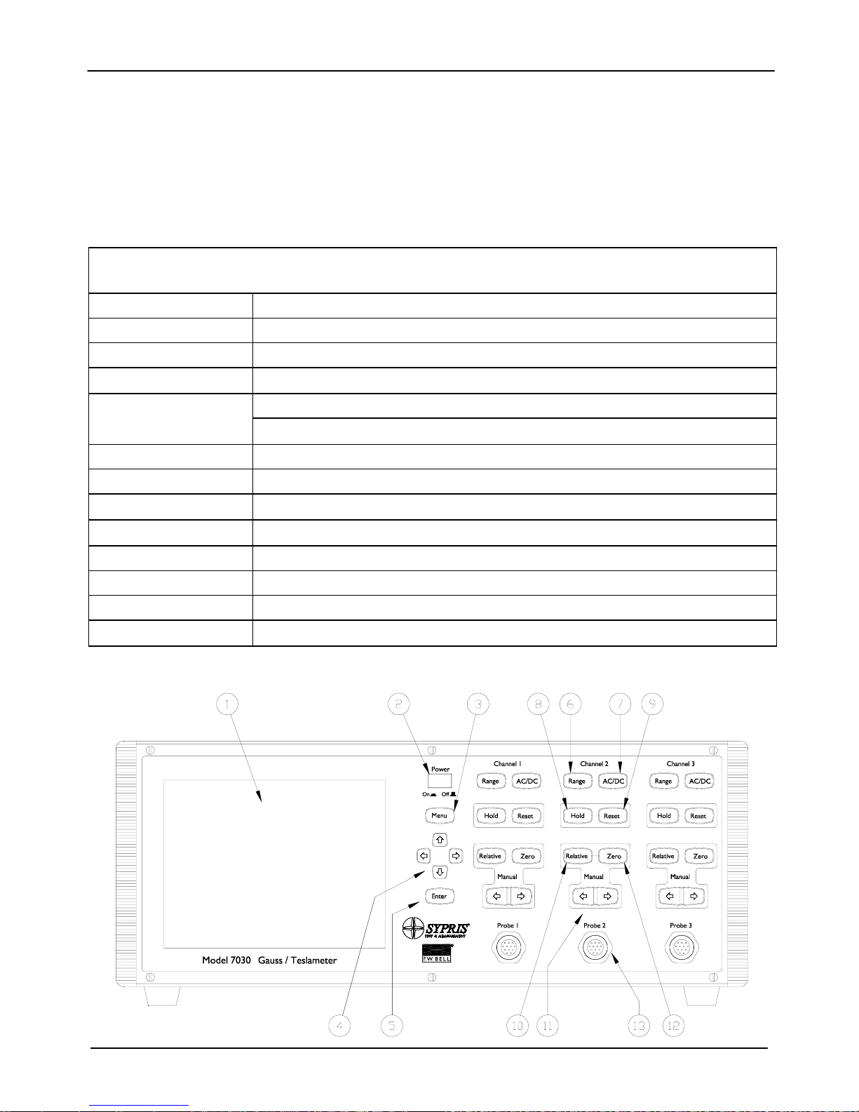
Front Panel
The front panel consists of the ¼ VGA display, keypad, probe
connectors, and power switch.
TABLE 1-2 FRONT PANEL DESCRIPTION
(1) Display
(2) Power Switch
(3) Menu Key
(4) Direction Keys
(5) Enter Key
(6) Range Key
(7) AC/DC Key
(8) Hold Key
(9) Reset Key
(10) Relative Key
(11) Manual Adjust
(12) Zero Key
(13) Probe Connector
Figure 1-1 Front Panel
320 x 240 Pixel Electro-luminescent ¼ VGA display, Multi-Shade Amber Color
Push Button Type Power Switch
Used to Enter and Leave the Menu System
Used to Navigate the Menu System
Activates / De-activates Selections in the Menu System
Acts as a Shift Key from the Measurement Screen
Selects Fixed Ranges or Autorange
Selects ac or dc Field Measurement
Activates / Deactivates the Hold Feature
Resets the Min/Max and Peak/Valley Detectors Used with the Hold Feature
Activates / De-activates the Relative Function
Adjusts the Relative or Zero Setting Up and Down
Starts the Channel’s Zeroing Process
12 Pin Non-Magnetic Female Connector for Hall Effect Probes
1-6 Section 1 - Introduction
F.W. BELL Model 7030 Gauss/Tesla Meter Instruction Manual
GENERAL
DESCRIPTION
(Continued)
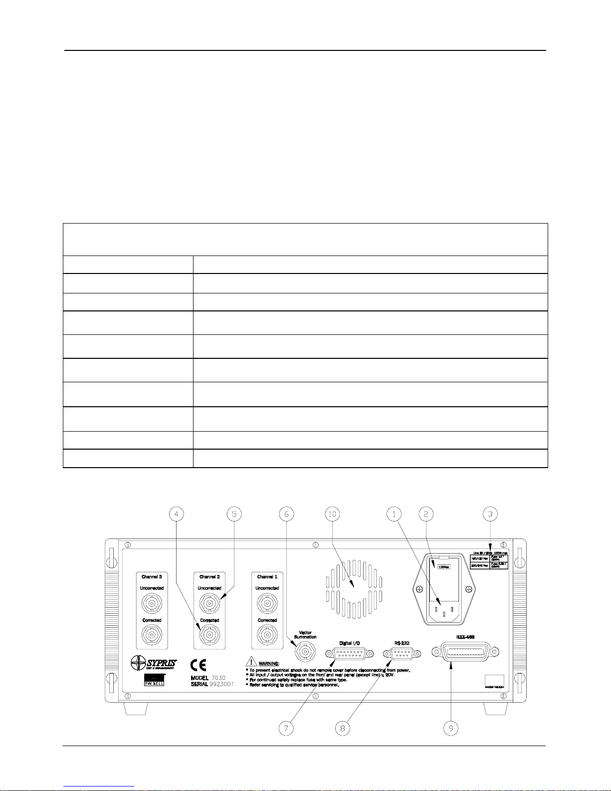
Rear Panel
The rear panel consists of the power receptacle, fuse holder, line
voltage switch, analog signal outputs, communication ports, and
the cooling fan vent.
TABLE 1-3 REAR PANEL DESCRIPTION
(1) Power Receptacle
(2) Fuse Panel
(3) Fuse Chart
(4) Corrected Analog
Output
(5) Uncorrected Analog
Output
(6) Vector Summation
Analog Output
(7) Digital I/O
(8) RS-232
(9) IEEE-488 (GPIB)
(10) Cooling Vent
Figure 1-2 Rear Panel
Accepts an International Instrumentation Power Line Cord
Panel Opens to Access Fuses and Line Voltage Switch
Specifies the Proper Fuse Rating
Compensated Analog Output Voltage Signal, Standard BNC Connector.
Uncompensated Analog Output Voltage Signal, Standard BNC Connector.
Analog Voltage Signal Proportional to the Three Channels’ Vector Sum,
Standard BNC Connector.
Standard 15 Pin “D” Type Female Connector, Provides Switch Closure Points
for Classifier Operation
RS-232 Serial Communication Port. Standard 9 Pin “D” Type Female
Connector.
Standard 24-Pin GPIB Connector for IEEE-488 Bus
Vents for Cooling Fan (Should Remain Clear)
Section 1 - Introduction 1-7
F.W. BELL Model 7030 Gauss/Tesla Meter Instruction Manual
GENERAL
DESCRIPTION
(Continued)
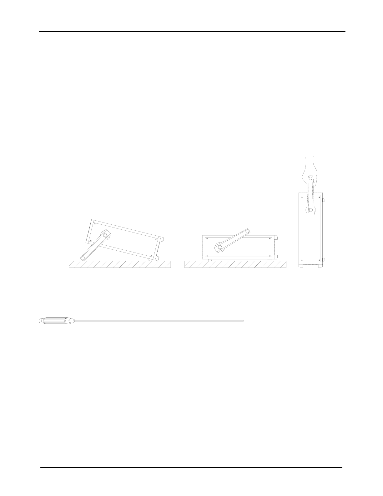
Cabinet
The cabinet is equipped with a rotating handle that also serves to
adjust the tilt angle of the instrument. If necessary, the handle is easily
removed with a standard Phillips screwdriver. The rear of the housing
features protruding feet that allow the instrument to be placed down in
a vertical position, without damage to the rear panel. Figure 1-3
shows the instrument in various positions.
Figure 1-3 Various Positions of Instrument
Raised Lowered
APPLICATIONS
• Sorting or performing incoming inspection on permanent magnets,
particularly multi-pole magnets.
Testing audio speaker magnet assemblies, electric motor armatures
•
and stators, transformer lamination stacks, cut toroidal cores, coils
and solenoids.
Determining the location of stray fields around medical diagnostic
•
equipment.
Determining sources of electromagnetic interference.
•
Locating flaws in welded joints.
•
Inspection of ferrous materials.
•
• 3-dimensional field mapping.
• Inspection of magnetic recording heads.
• Designing new magnetic assemblies.
Carrying
1-8 Section 1 - Introduction
F.W. BELL Model 7030 Gauss/Tesla Meter Instruction Manual
µ
Section 2 Specifications
INSTRUMENT
Full-scale ranges are shown in the Tables 2-1a – 2-1c below; listed by probe type. In all cases, the
resolution is 1 part in 300,000.
Table 2-1a: Ranges for Low Field Probe:
gauss (G) tesla (T) oersted (Oe) ampere-turn/meter (A/m)
300.000 mG
3.00000 G 300.000 µT 3.00000 Oe 238.732 A/m
Note: Low Field probe cannot be used for measurements above 2 Gauss.
30.0000
T
300.000 mOe 23.8732 A/m
Table 2-1b: Ranges for Mid Field Probe:
gauss (G) tesla (T) oersted (Oe) ampere-turn/meter (A/m)
30.0000 G 3.00000 mT 30.0000 Oe 2.38732 kA/m
300.000 G 30.0000 mT 300.000 Oe 23.8732 kA/m
3.00000 kG 300.000 mT 3.00000 kOe 238.732 kA/m
30.0000 kG 3.00000 T 30.0000 kOe 2.38732 MA/m
Table 2-1c: Ranges for High Field Probe:
gauss (G) tesla (T) oersted (Oe) ampere-turn/meter (A/m)
300.000 G 30.0000 mT 300.000 Oe 23.8732 kA/m
3.00000 kG 300.000 mT 3.00000 kOe 238.732 kA/m
30.0000 kG 3.00000 T 30.0000 kOe 2.38732 MA/m
300.000 kG 30.0000 T 300.000 kOe 23.8732 MA/m
Section 2 - Specifications 2-1

F.W. BELL Model 7030 Gauss/Tesla Meter Instruction Manual
Table 2-2 Accuracies @23°C ( Instrument Only *)
Display and Digital
Outputs (min speed)
±0.05% of reading and
dc accuracy
±0.01% of range
ac accuracy
In dc mode
ac accuracy
in ac mode
ac peak accuracy
N/A
2.0% of reading ± 0.15% of
range (20 Hz to 50 kHz)
5.00% of Reading N/A N/A
*Probes Errors Not Included
Corrected Analog Output and
Digital Outputs (max speed)
±0.15% of 3V or 10V ranges
2% of range
dc to 100 hz
2.0% of 3V or 10V ranges
(ac 20 to 500 Hz)
(ac rms (dc) 20Hz-50kHz)
Uncorrected Analog
Output
3V range: 0.25% of
reading ±40mV
10V range: 0.25% of
reading±120mV
2% of range
dc to 100Hz
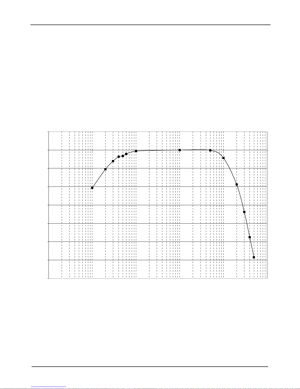
See Figure 2-1 for Graph
(Typical)
ac and ac rms (dc) output
2-2 Section 2 - Specifications

F.W. BELL Model 7030 Gauss/Tesla Meter Instruction Manual
Min / Max Hold Acquisition Time:
dc Mode: 200mS
ac Mode: 200mS
Peak / Valley Hold Acquisition Time:
dc Mode: 2ms
ac Mode: 200µs
Temperature Coefficient:
0.02% of reading
±1 count/degree celsius
Update Rate:
Display: 5/s (max)
IEEE Output: 100/s (max)
RS-232 Output: 100/s (max)
Temperature Range:
Operating: 0 to 50 degrees celsius
Storage: -20 to 60 degrees celsius
Humidity Range:
0 to 35 degrees celsius 80% RH
Corrected Analog Output Noise
(3V output range with 500 Hz filter):
All ranges:
2mV rms (35mV p-p)
Un-Corrected Analog Output Noise
(3V output range with 500 Hz filter):
300G, 3kG, 30kG ranges:
50µV rms (10mV p-p)
30G range:
2mV rms (20mV p-p)
Analog Output Impedance:
<100 Ohms
Analog Output Connector:
Standard BNC
Analog Output Scaling:
dc Mode: 3V or 10V standard
± 0.1V to ± 9.9V adjustable,
with increments of 0.1 V
ac Mode: 3Vrms or 10Vrms standard
± 0.1Vrms to ± 9.9Vrms adjustable,
with increments of 0.1 Vrms
Front Panel Display:
Type: ¼ VGA 320 x 240 pixels graphic Electro-
luminescent display with 4 shades of
amber.
Dimensions: 4.7 W x 3.5 H inches
119 W x 89 H millimeters
Power:
Volts: 100/120 220/240
Frequency: 50-60 Hz or 50-60 Hz
Current: 1.0 A (max) 0.5 A (max)
Size:
16.3 W x 5.2 H x 13.5 D inches
414 W x 132 H x 343 D millimeters
Weight:
Net: 19.4 lbs. / 8.8 kg
Shipping: 25.8 lbs. / 11.6 kg
Warm-up Time to Rated Accuracy:
60 Minutes
Section 2 - Specifications 2-3
F.W. BELL Model 7030 Gauss/Tesla Meter Instruction Manual
Figure 2-1 Frequency Response of Uncorrected Analog Outputs (Typical)
No Probe (Instrument Only)
5.00
0.00
1 10 100 1000 10000 100000
-10.00
-15.00
-20.00
PERCENT OF READING ERROR
-25.00
-30.00
-35.00
-5.00
FREQUENCY (Hz)
2-4 Section 2 - Specifications
F.W. BELL Model 7030 Gauss/Tesla Meter Instruction Manual
Ω
±
±
Communications
EMC application note
Use only high quality, double shielded cables for the RS-232, IEEE-488 and Digital I/O connections. Keep
the length of the cables less than 3 meters. Cables greater than 3 meters with insufficient EMI shielding can
cause excessive emissions or may be susceptible to external interference. Adapters specified below for the
RS-232 and digital I/O connectors must be used prior to connecting the RS 232 and digital I/O cables.
Connection Description Insertion Loss Spectrum Control Part #
RS-232 830pF Capacitive Type Filter,
“D” Type 9 Pin Male to Female
Digital I/O 1000pF Capa citive Type Filter,
“D” Type 15 Pin Male to Female
22dB @ 100MHz,
39dB @ 1GHz
20dB @ 100MHz,
40dB @ 1GHz
56-705-008 , 830 pF
56-715-002, 1000 pF
Serial
Format: RS-232C
Connector type: 9-pin “D” female
Cable length: 3 m (9.8 ft.) maximum
Receive input resistance:
Receive voltage limit:
Transmit output voltage:
Baud rate:
Stop bits: 1, 2
Character length: 7,8
Parity: None, Odd, Even
Handshaking None, Hardware, Software
Standards supported: IEEE-1987.2, SCPI-1999
3 k
minimum
30 V maximum
5 V min, ± 8 V typical
300, 600, 1200, 2400, 4800, 9600, 19200, 38400
IEEE 488.2 (GPIB)
Format: IEEE 488.2
Standards supported: IEEE-1987.2, SCPI-1999
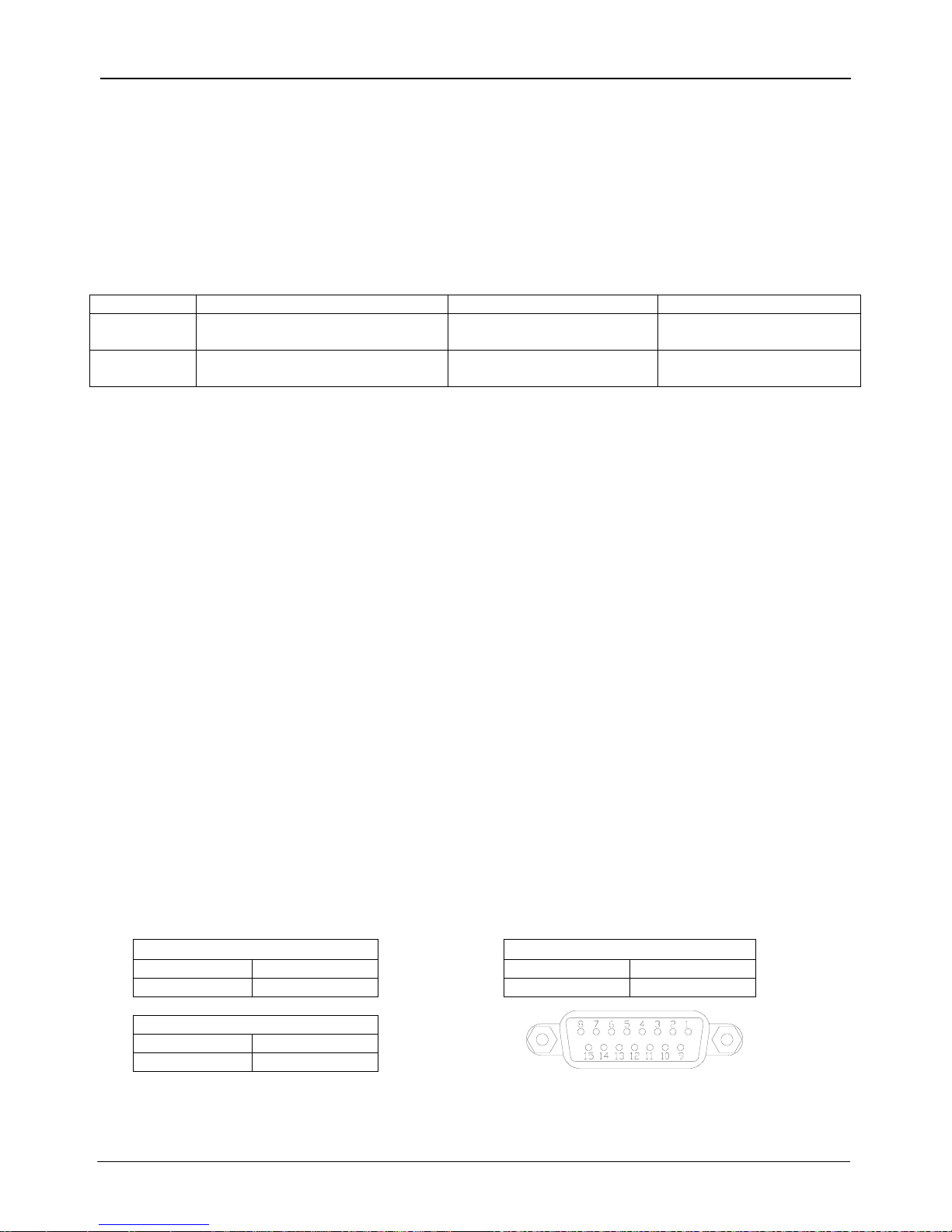
Digital I/O
Signal Type:
Relay Closure
Connector: 15-Pin “D” Female
Switching Voltage:
100 V dc or ac Peak MAX
Switching Current: 0.25 A dc or ac Peak MAX
Operating Time, Including Bounce:
2 mS MAX
Classifier Connections
Channel 1
Low
High
1,9
2,10
Channel 2
Low
High
3,11
4,12
Note: Do not connect to pins 7, 8, 15 Pin “D”
and 15; factory use only! Figure 2-2 Digital I/O Connector
Channel 3
Low
High
5,13
6,14
Section 2 - Specifications 2-5

F.W. BELL Model 7030 Gauss/Tesla Meter Instruction Manual
Regulatory Information:
Compliance was demonstrated to the following specifications as listed in the official Journal of the European
Communities:
EN 50082-1:1997 Generic Immunity
EN 61000-4-2 Electrostatic Discharge (ESD) Immunity
EN 61000-4-3 and Radiated Electromagnetic Field (RF) Immunity
EVN 50204
EN-61000-4-4 Electrical Fast Transient/Burst (EFT) Immunity
EN-61000-4-5 Electrical Surge Immunity
EN-61000-4-6 Conducted RF Disturbance Immunity
EN-61000-4-8 Power Frequency Magnetic Field Immunity
EN 50081-1:1992 Generic Emissions
EN 55022 Class B and Radiated and Conducted Emissions
EN 55014
EN61010-1: 1993 and Safety
EN61010-1 A2:1995
Safety Requirements for Electrical Equipment for Measurement,
Control, and Laboratory use.
CALIBRATION
SERVICE
The instrument is calibrated at the factory prior to shipment. To maintain
rated accuracy, it is recommended that the instrument be re-calibrated
every 12 months.
Answers to any questions concerning the calibration of this instrument
may be obtained by contacting OECO at the address below:
OECO, LLC
4607 SE International Way
Milwaukie, OR 97222
Phone: 503-659-5999
2-6 Section 2 - Specifications
F.W. BELL Model 7030 Gauss/Tesla Meter Instruction Manual
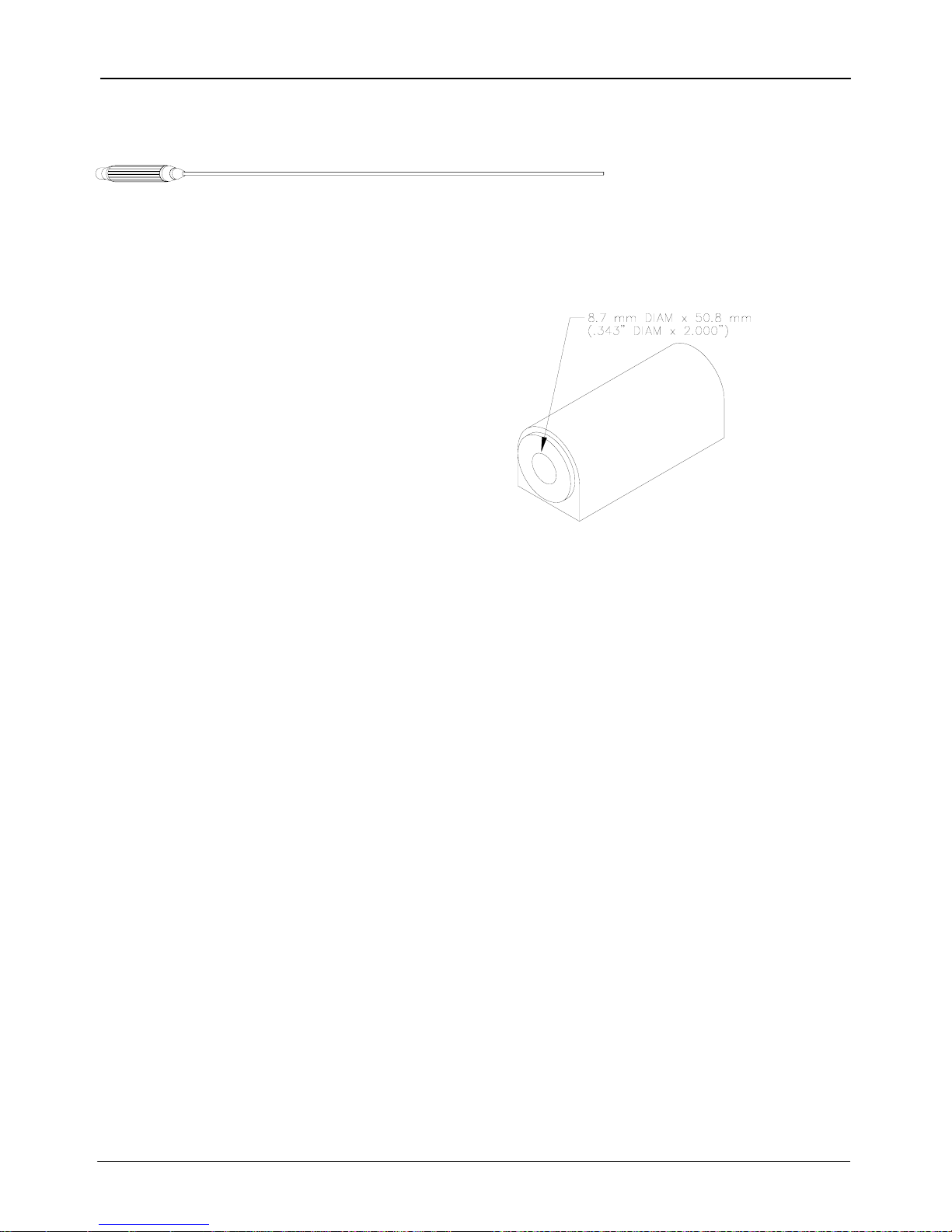
ZERO FLUX CHAMBER
Model Number:
YA-111
Cavity Dimensions:
Length: 50.8 mm (2”)
Diameter: 8.7 mm (0.343”)
Attenuation:
80 dB to 30 mT (300 G)
Purpose: Figure 2- 3
To shield the probe from external magnetic fields
during the ZERO or RELATIVE operations.
Zero Flux Chamber
Section 2 - Specifications 2-7


THIS SIDE BLANK !
(Rear of page 2-7)

F.W. BELL Model 7030 Gauss/Tesla Meter Instruction Manual
Section 3
OVERVIEW
Probes
F.W. Bell’s 7000 series gauss/tesla meter probes are designed to meet
the electrical and mechanical requirements of virtually any application.
Models are available for transverse, axial, 3-axis and very low field
measurements. The probe style is dependent upon the measurement
environment. The standard fiberglass stem is recommended for
laboratory or light handling environments, while the heavy duty aluminum
stem is recommended for harsher environments. The probe’s length,
outside diameter (axial probes) or thickness and width (transverse
probes) are important if there are physical constraints where the probe
will be used.
In “transverse” probes the Hall generator is mounted in a thin, flat stem
whereas in “axial” probes the Hall generator is mounted in a cylindrical
stem. The primary difference is the axis of measurement, as shown by
“+B” in Figure 3-2. Generally transverse probes are used to make
measurements between two magnetic poles such as those in audio
speakers, electric motors and imaging machines. Axial probes are often
used to measure the magnetic field along the axis of a coil or solenoid.
Either probe can be used where there are few physical space limitations,
such as in geomagnetic or electromagnetic interference surveys.
A 3-axis probe is a special configuration of three sensing elements
positioned orthogonally within a cylindrical stem. The instrument can
provide a separate reading for each axis as well as a vector sum of all
three axes.
The low field probe is designed for high sensitivity, volumetric
measurement such as mapping variations in the earth’s magnetic field or
detecting the presence of ferrous objects.
Handle Hall probes with care. Do not bend the stem or apply
pressure to the probe tip as damage may result.
Section 3 - Probes 3-1
F.W. BELL Model 7030 Gauss/Tesla Meter Instruction Manual
PROBE
VARIATIONS
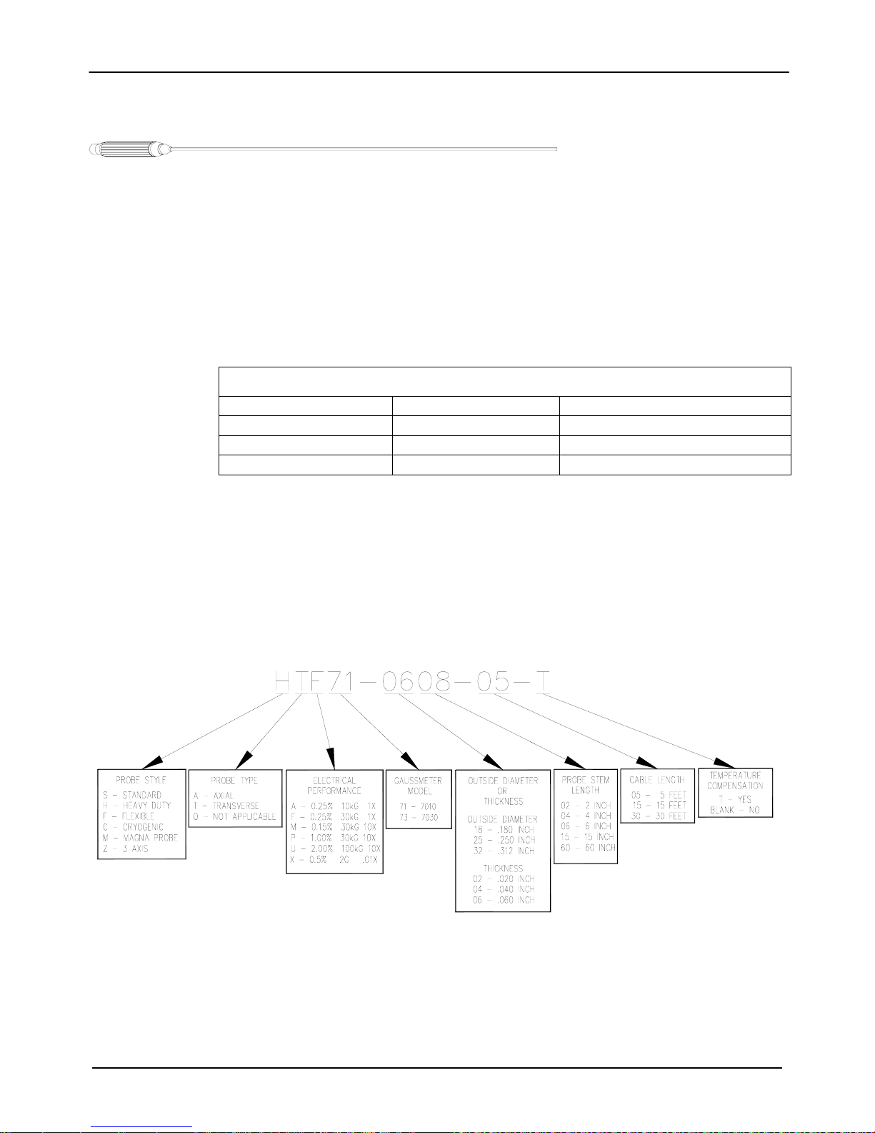
A wide variety of probes are available for use with the 7030 gauss/tesla meters.
The types include 3-axis, heavy-duty transverse and axial, standard transverse
and axial, standard transverse with exposed element, flexible transverse and axial
with exposed element and low field probes. All of these probes are available with
or without temperature compensation. All probes are available with 5, 15 or 30
foot (1.5, 4.5 and 9 meter) cable lengths and most are available with various stem
lengths. Table 3-1 lists the maximum field measurement capabilities and
resolutions.
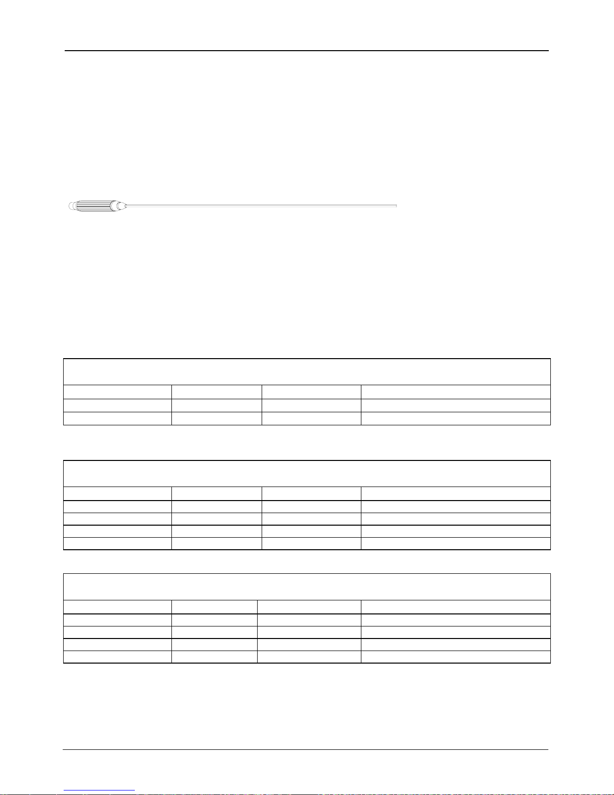
Table 3-1 Probe Maximum Field Levels and Resolutions
Probe Type Maximum Field Resolution
Low Field
2 G (200 µT) 1 µG (0.1 nT)
Medium Field 30 kG (3 T)
High Field 300 kG (30 T)
Figure 3-1 serves as an ordering guide for F.W. BELL 7000 series probes.
Full electrical and mechanical specifications of all probes are available on
request.
Figure 3-1 7000 Series Probe Ordering Guide
Note: Probes are not available in all part number combinations.
0.1 mG (0.01 µT)
1 mG (0.1 µT)
3-2 Section 3 - Probes
F.W. BELL Model 7030 Gauss/Tesla Meter Instruction Manual
PROBE
MEMORY
The connector of each probe contains a memory device which stores
registration information (model number, serial number, date calibrated, etc.)
as well as performance information for Hall generator sensitivity, linearity,
frequency response and temperature response. Each probe is physically
identified with model number, serial number and a maximum voltage rating of
“30VRMS / 60Vdc MAX” on a durable polyester label wrapped around the
cable jacket.
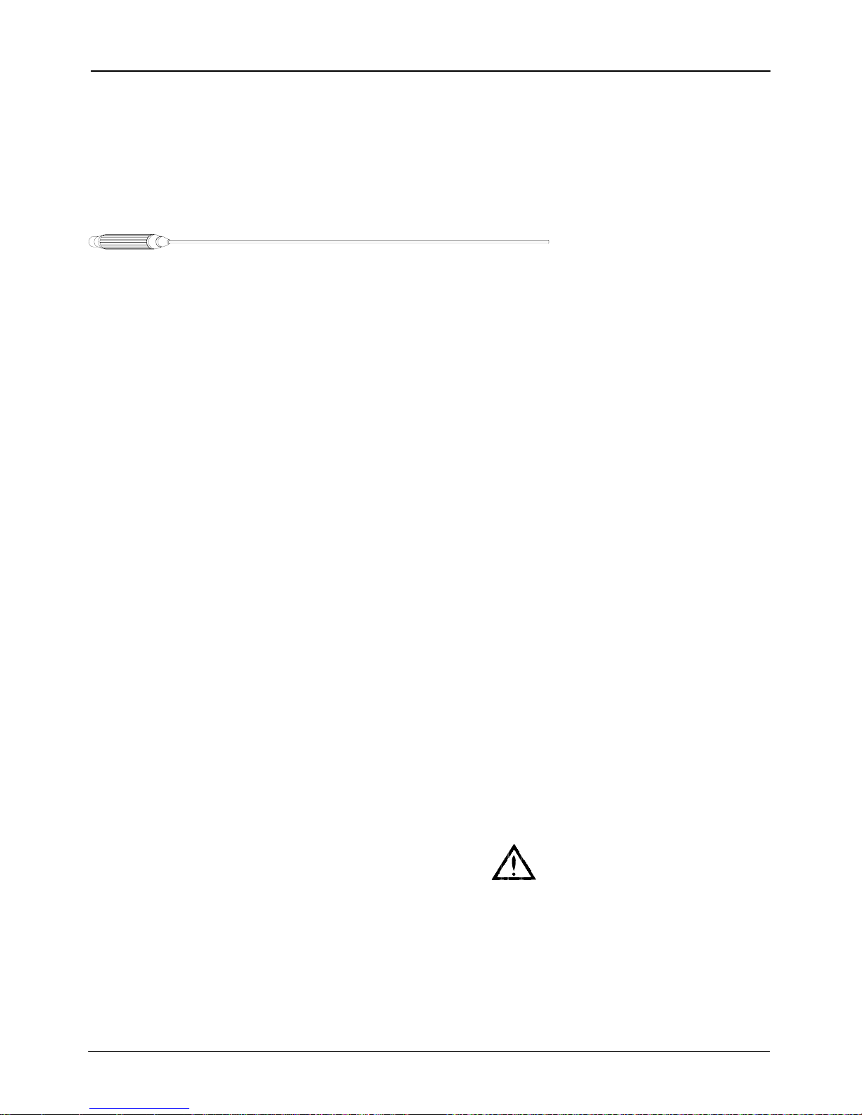
PROBE STEM
All probes except the low field probe are supplied with a rigid stem cover to
protect the probe when not in use. It is strongly recommended to use the
stem protector when storing the probe or when the probe will not be used for
any length of time. If a probe stem becomes damaged it can not be repaired.
TEMPERATURE
EFFECTS
All Hall probes have an initial electrical offset that will affect the accuracy of
static (dc) field measurements. This offset should be canceled using the
instrument’s “zero” function. However, the probe’s offset and sensitivity will
change with temperature. Using temperature-compensated probes will
minimize these effects.
There can be substantial errors in uncompensated probes. A typical probe’s
dc offset can change by ± 0.1 G / °C (±10 µT / °C). It is best to allow the
probe’s temperature to stabilize before performing a “zeroing” operation.
Zeroing is discussed in Section 6 – Flux Density Measurement. The
probe’s sensitivity will decrease as temperature increases. Probes are
calibrated at ambient temperature (23 °C). A typical probe may change by
–0.05% / °C. For instance a reading of 200 mT at 23°C may drop to 197 mT
at 50°C.
FIXTURING
In some applications it may be necessary to install a probe into a holding
fixture to maintain a constant probe position. If this becomes necessary, do
not clamp onto the probe stem as this will most likely damage the probe.
Rather, clamp onto the aluminum probe body.
Section 3 - Probes 3-3

F.W. BELL Model 7030 Gauss/Tesla Meter Instruction Manual
Figure 3-2 Hall Probe Configurations
3-4 Section 3 - Probes
 Loading...