

Page 1
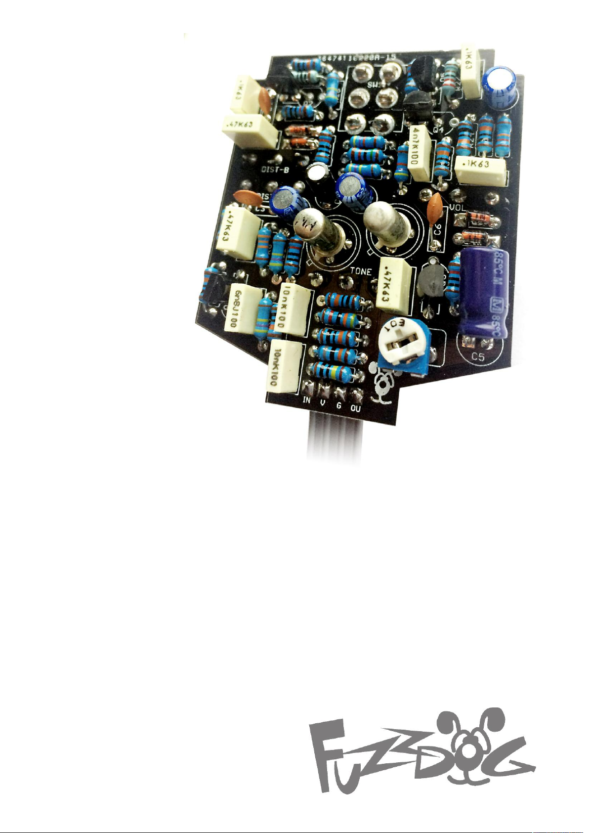
Muff-based bass fuzz
with germanium growl
Contents of this document are ©2017 Pedal Parts Ltd.
No reproduction permitted without the express written
permission of Pedal Parts Ltd. All rights reserved.
Animatron
Page 2
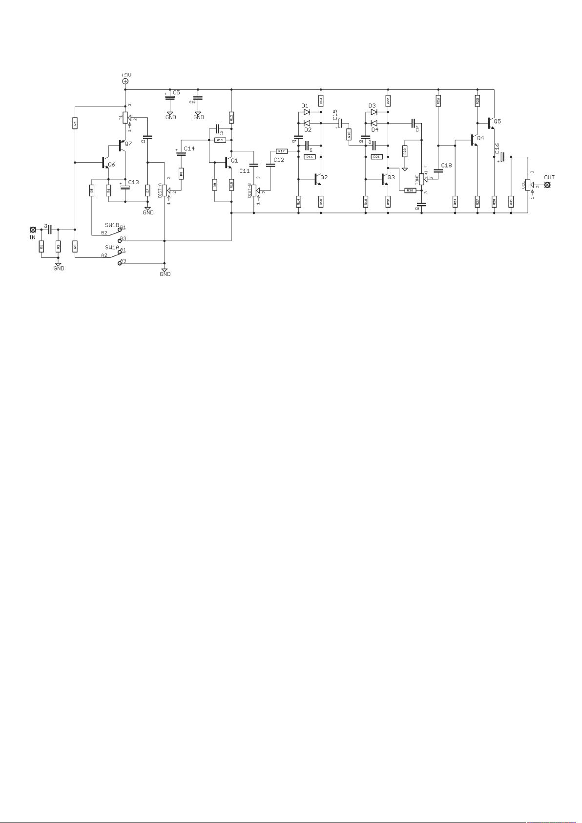
Schematic + BOM
*The original circuit uses
C2240, but you could try
other BJT. The circuit is
basically a Big Muff Pi.
C2240 have a nonstandard pin-out so there
are extra pads on the PCB
to accomodate those and
standard CBE cans. See
later in this document for
more info on that.
**NTE102/3 in the
original, but you can try
other germaniums. We
supply AC128/AC176
which work well. You
could replace these with
silicon if you prefer.
R1 1M
R2 100K
R3 100K
R4 680K
R5 4K7
R6 4K7
R7 470K
R8 33K
R9 100K
R10 470R
R11 470K
R12 10K
R13 10K
R14 100K
R15 100R
R16 470K
R17 10K
R18 10K
R19 100K
R20 100R
C1 10n
C2 6n8
C3 470p
C4 470p
C5 100u
C6 470p
C7 100n
C8 100n
C9 10n
C10 100n
C11 470n
C12 470n
C13 2u2
C14 10u
C15 10u
C16 10u
C17 4n7
C18 1u
‡
D1-4 1N4148
***10K in original but
we’ve made it bigger to
accommodate a wider
range of germaniums.
‡
Yes, C18 is shown as
470n in the cover pic.
We were all out of 1u
when we built it.
R21 470K
R22 15K
R23 100K
R24 100K
R25 10K
R26 470K
R27 2K2
R28 12K
R30 39K
R31 100K
Q1-5 C2240*
Q6 NPN Ge**
Q7 PNP Ge**
DIST 100KA Dual Gang
TONE 100KB
VOL 100KB
T1 22K trimmer***
SW1 DPDT ON-ON
Page 3
The power and signal pads on the PCB conform
to the FuzzDog Direct Connection format, so can
e paired with the appropriate daughterboard for
b
quick and easy offboard wiring. Check the
separate daughterboard document for details.
Be very careful when soldering the diodes and
transistors. They’re very sensitive to heat. You
should use some kind of heat sink (crocodile clip
or reverse action tweezers) on each leg as you
solder them. Keep exposure to heat to a
minimum (under 2 seconds).
Snap the small metal tag off the pots so they can
be mounted flush in the box.
Positive (anode) legs of the electrolytic caps go to
the square pads. C5 can be bent back over the
adjacent resistors to save on height - see the
cover image.
Negative (cathode) legs of the diodes go to the
square pads.
PCB layout ©2017 Pedal Parts Ltd.
You should solder all other board-mounted
components before you solder the pots. Once
they’re in place you’ll have no access to much of
the board. Make sure your pots all line up nicely.
The best way to do that is to solder a single pin of
each pot in place then melt and adjust if
necessary before soldering in the other two pins.
If your pots don’t have protective plastic jackets
ensure you leave a decent gap between the pot
body and the PCB otherwise you risk shorting out
the circuit.
Same goes for the toggle switch. Use your
enclosure as a guide for positioning them to
ensure they line up properly. Solder one lug, then
melt it and adjust to get it straight before
soldering any others.
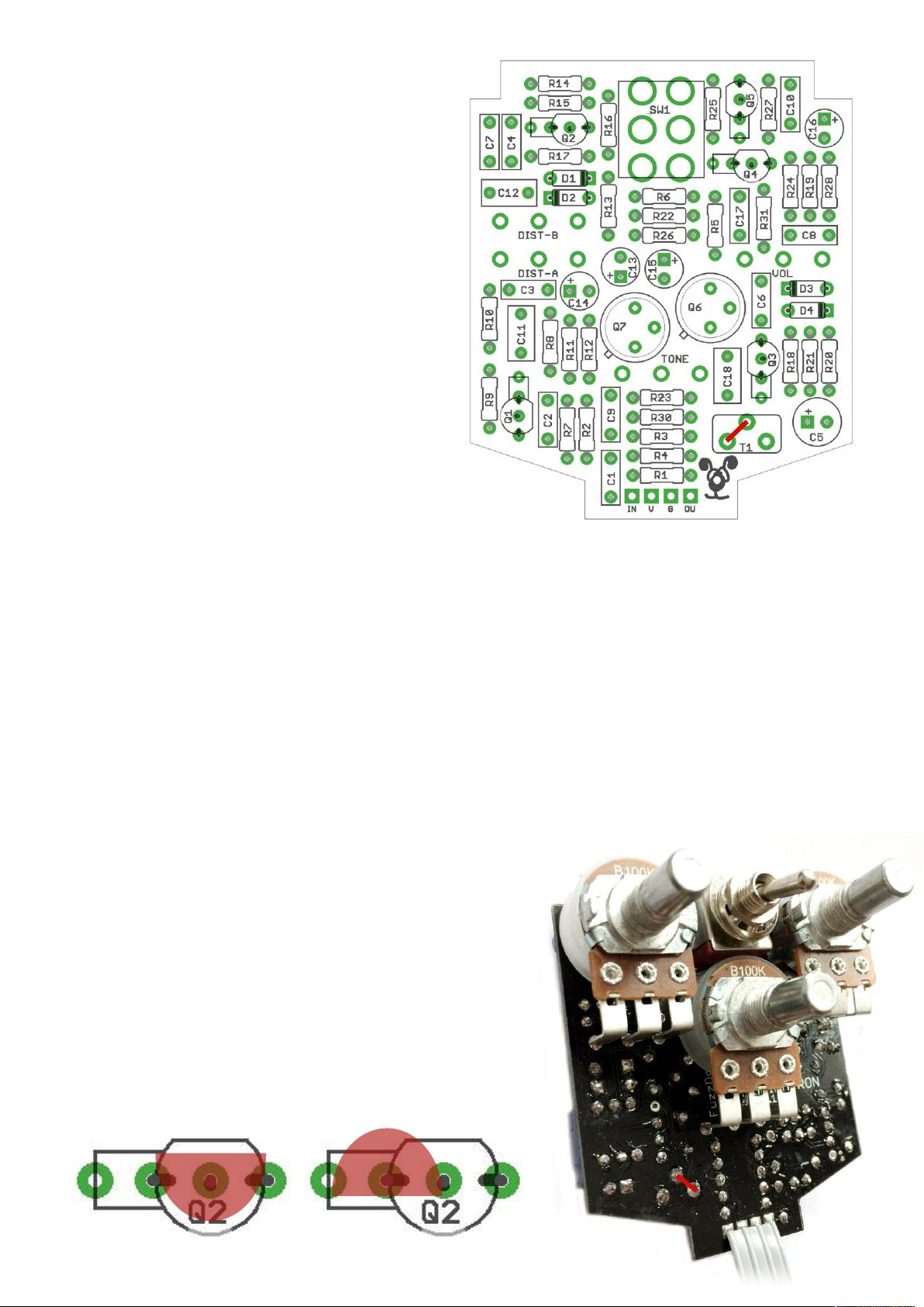
Trimmer T1 is used to bias Q6-7. There’s no ‘right’
setting, just do it by ear until it sounds sweet
SMALL HACK-ETTE
You need to jumper two of the trimmer pads
together. The original schematic shows T1 as a
voltage divider which is unlikely to work except for
a very small selection of Q6-7 pairings.
Jumpering pins 1+2 changes the configuration so
thta C2 is coming straight from the emitter of Q7
which makes much more sense. Jumper shown
in red above and below.
TRANSISTOR ORIENTATION
Standard EBC transistors
such as 2N5088 orientate
like this:
C2240 are ECB, so should be
placed like this:
Page 4
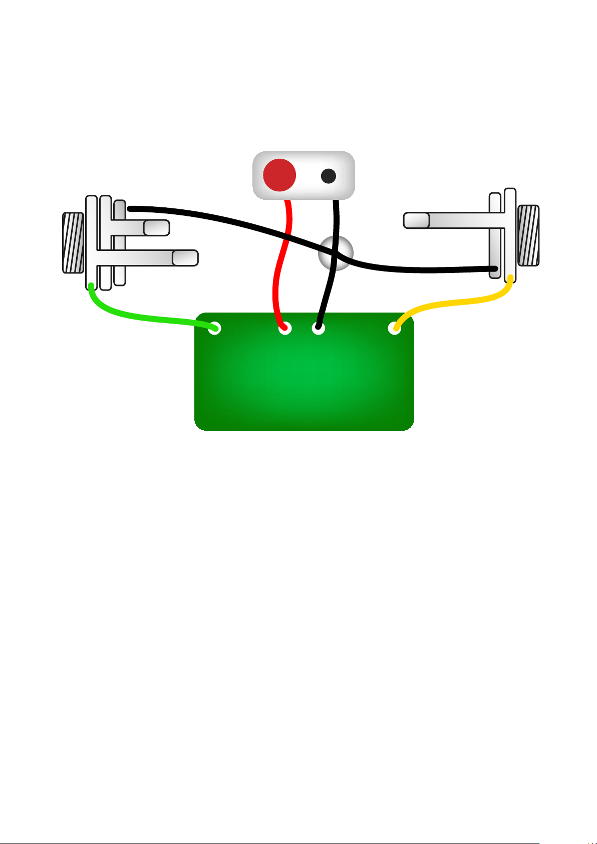
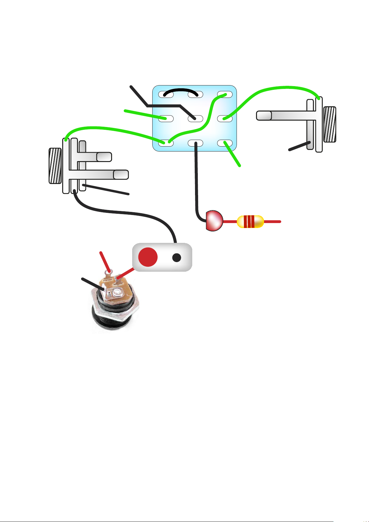
Test the board!
BATTERY
IN
OUT
Your nice, new circuit board
INCLUDING WIRED POTS!!!!
IN 9V GND OUT
UNDER NO CIRCUMSTANCES will troubleshooting help
be offered if you have skipped this stage. No exceptions.
Once you’ve finished the circuit it makes sense to test is before starting on the switch and
LED wiring. It’ll cut down troubleshooting time in the long run. If the circuit works at this
stage, but it doesn’t once you wire up the switch - guess what? You’ve probably made a
mistake with the switch.
Solder some nice, long lengths of wire to the board connections for 9V, GND, IN and OUT.
Connect IN and OUT to the jacks as shown. Connect all the GNDs together (twist them up
and add a small amount of solder to tack it). Connect the battery + lead to the 9V wire,
same method. Plug in. Go!
If it works, crack on and do your switch wiring. If not... aw man. At least you know the
problem is with the circuit. Find out why, get it working, THEN worry about the switch etc.
Page 5
L
E
D
BOARD
OUT
BOARD
9V
BOARD
GND
BOARD
GND
BOARD
GND
BOARD
INPUT
BATTERY
+
IN
OUT
L
E
D
BOARD
GND
BOARD
9V
+
Wire it up (if using a daughterboard please refer to the relevant document)
Wiring shown above will disconnect the battery when you remove the jack plug
from the input, and also when a DC plug is inserted.
The Board GND connections don’t all have to directly attach to the board. You
can run a couple of wires from the DC connector, one to the board, another to
the IN jack, then daisy chain that over to the OUT jack.
It doesn’t matter how they all connect, as long as they do.
This circuit is standard, Negative GND. Your power supply should be Tip
Negative / Sleeve Positive. That’s the same as your standard pedals (Boss etc),
and you can safely daisy-chain your supply to this pedal.
Page 6
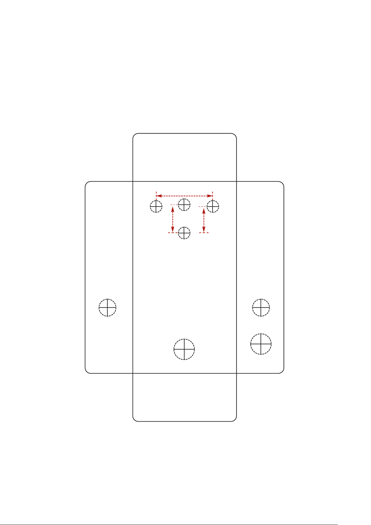
Drilling template
Hammond 1590B
60 x 111 x 31mm
It’s a good idea to drill the pot and
toggle switch holes 1mm bigger if
you’re board-mounting them.
Wiggle room = good!
Recommended drill sizes:
Pots 7mm
Jacks 10mm
Footswitch 12mm
DC Socket 12mm
Toggle switch 6mm
32mm
6mm
1
15mm
This template is a rough guide only. You should ensure correct marking of your
enclosure before drilling. You use this template at your own risk.
Pedal Parts Ltd can accept no responsibility for incorrect drilling of enclosures.
FuzzDog.co.uk
 Loading...