

Page 1
semi-modlar analog synthesizer
Operation Manal
Page 2
Written and produced by Jered Flickinger
Copyright 2007
Future Retro Synthesizers
Page 3

TABLE OF CONTENTS
1
Introduction
2. Welcome
Overview
Power
Care
Warranty
Rack-Mount or Desktop
3. Installing the side pieces
Getting Started
4. I want to play it now!
Basic system setup
5. Basic Patch Sheet
Connections
6. MIDI and 1/4” Connections
7. 1/4” Connections
8. 1/4” and Power Connections
Overview of Analog Synthesis
9. Frequency
Harmonic Content
10. Amplitude
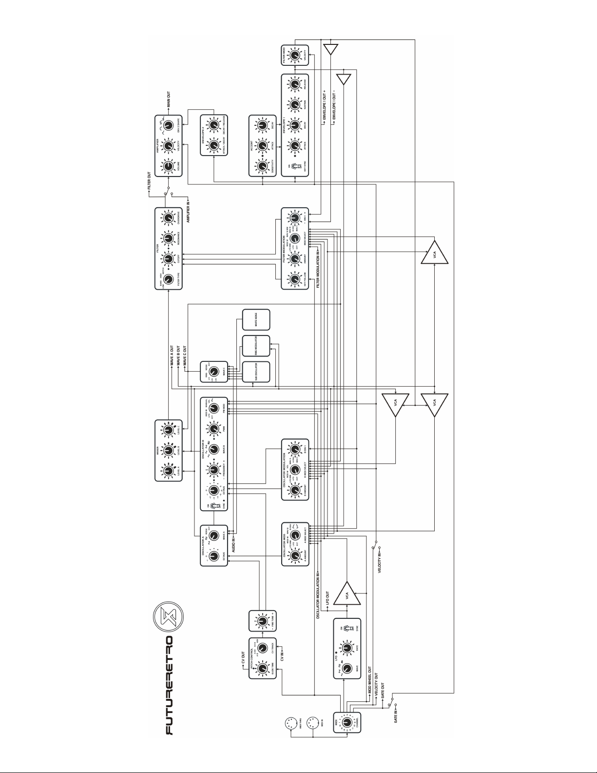
Internal Signal Routing
11. Diagram
Controlling Your XS
12. Using MIDI
13. MIDI to CV/Gate Converter
14. Using CV/Gate Control Signals
Analog Controls
15. Glide Time
CV Track
16. Low Frequency Oscillator
17. Oscillator A
18. Oscillator B
21. Wave C
22. Oscillator A Modulation
24. Oscillator B Modulation
25. Mixer
26. Multimode Filter
27. Filter Modulation
30. Envelope 1
31. Accent
32. Envelope 2
33. Amplifier
Patch Sheets
34. Blank Patch
35. Noise Kick
36. Techno Kick
37. Snare Drum
Patch Sheets
38. Hand Clap
39. High Hats
40. Distorted Bass/Lead
41. Funky Trance Lead
42. Classic Sync Lead
43. Phat Saw
44. Acid Bass
45. Jungle Bass
46. Winding Down
47. Buzzy Bass
48. 8 Bit Talking Bass
49. Electric Bass
50. Phat Stack Phased
51. Grinder
52. MIDI Synced Pseudo Arp
53. Computer
54. Strange Beats
Tips and Tricks
55. Latch a Note
Special uses for the oscillator outputs
56. Using CVIN as an additional mod source
Using the VEL IN as an FM source
A/B Envelope signals are Velocity-sensitive
Envelope signals that are not Velocity-sensitive
Using audio to trigger the envelopes
57. Sub oscillator sync
Sub oscillator self modulation
Overdriving the filter with two oscillators
Using the overdrive
Summing signals at the filter output
Trouble Shooting
58. Common Problems
Specifications
59. MIDI
LFO
Oscillator A
Oscillator B
Wave C
Oscillator Modulation
Mixer
Filter
60. Filter Modulation
Envelope 1
Accent Section
Envelope 2
Amplifier
Inputs/Outputs
Page 4

2
INTRODUCTION
Welcome to the world of XS!
Thank you for choosing the XS semi-modular analog synthesizer. Please take time to read through the
entire manual for a complete understanding of the operations and procedures needed to master this
instrument.
Contents
Included with your XS synthesizer, you should find an external power supply, optional desktop ends,
owner’s manual, and warranty card. If any of these items are missing, please notify the dealer you
purchased the unit from or contact Future Retro directly. Please keep the original box and all packaging
material your unit came with, as this provides the best protection should you ever need to ship your unit.
Overview
The XS is a true semi-modular analog synthesizer with a universe of sonic possibilities just waiting to be
discovered. The unit’s versatile design allows it to be used as either a tabletop or rack-mounted
instrument and its compact size makes it ideal for musicians on the go.
In its simplest form the XS is an extremely powerful monophonic synthesizer with internal signal routings pre-wired in a way that allows the unit to act similar to traditional synthesizers. The unit also provides numerous inputs and outputs that can be connected in various ways to override the pre-wired signal routings and interface the unit with other instruments in a modular fashion, and even process
external audio.
The XS can be controlled by both MIDI and CV/Gate control signals in a variety of ways so that
interfacing it with other instruments, old or new, is simple. The XS can also act as a MIDI to CV/Gate
converter, allowing MIDI information received by the unit to be transmitted as CV/Gate signals for
controlling other analog instruments.
Power
The power supply provided with your unit is designed specifically for this product. Do not substitute the
use of other power supplies. If your power supply ever becomes lost or damaged, please contact us for a
replacement.
Care
Avoid exposing the unit to smoke or damp, dusty, or extreme hot and cold environments. To clean the
unit, use a soft damp cloth. Do not use any abrasive cleaners, as these may harm the surfaces and finish
of the unit.
Product Warranty and Support
The XS comes with a 1 year limited warranty covering mechanical or electrical defects. To validate your
warranty, fill out the warranty card included with your unit and mail it within one month of the original
purchase date.
The warranty does not cover damage due to misuse or abuse of the product. Any modifications
performed to the unit will automatically void the warranty. Future Retro will not be held liable for any
accidents or damages caused to the user or their surroundings when using this product.
Should your unit become damaged within the warranty period, please email product support:
[email protected]
You will need to obtain authorization to return the unit to us for repairs.
Please visit the Product and Support pages of our website for the latest information about this product,
and any additional updates which may become available: www.future-retro.com
Page 5
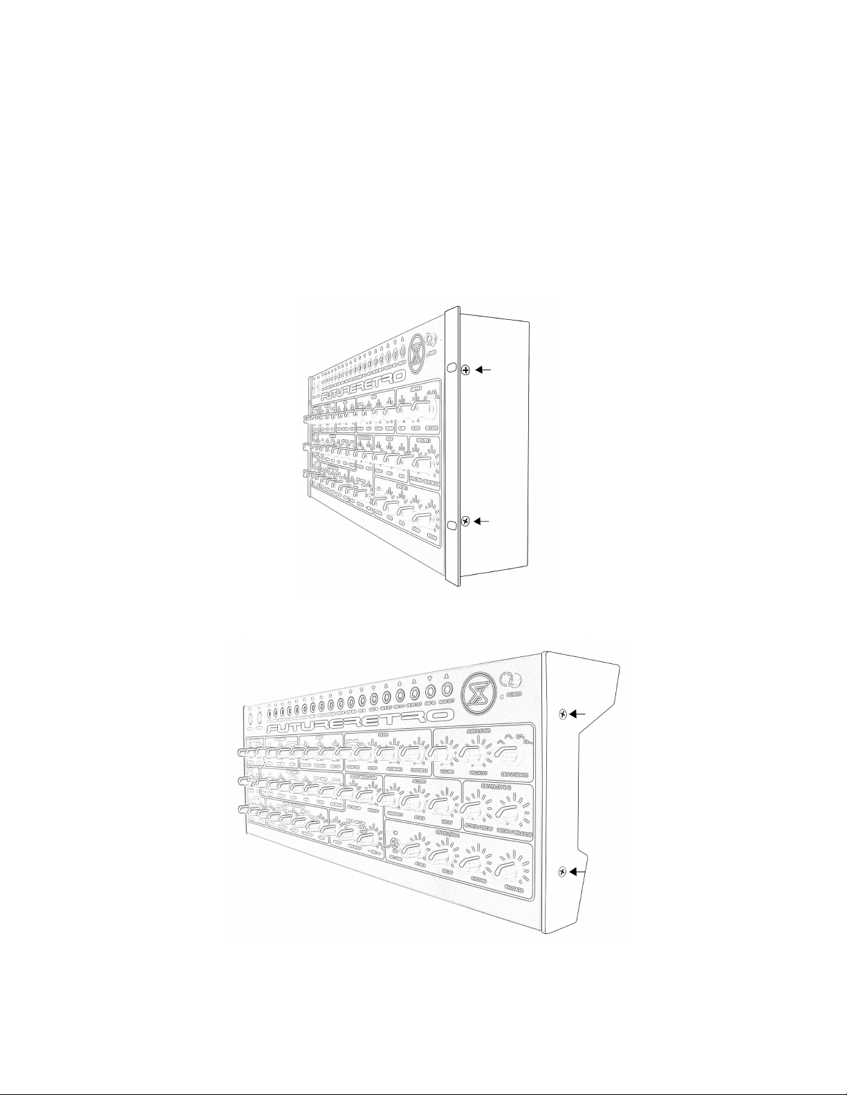
RACK-MOUNT OR DESKTOP
Have it your way
The XS can be used as either a rack-mount or desktop unit. All units come assembled with the rack ear
option installed at the factory. If you prefer to place the XS on a desktop, the rack ears may be removed
and these desktop pieces may installed in their place.
Remove the two Phillips screws on each of the rack ear end pieces, and install the desktop pieces as
shown below. The Phillips screws that are used to fasten the rack ears can be reused for mounting the
desktop pieces.
3
Page 6
6. Now you can play around with the various analog parameter settings to adjust the sound that
4
GETTING STARTED
I want to play now!
To play the XS, follow these directions in order.
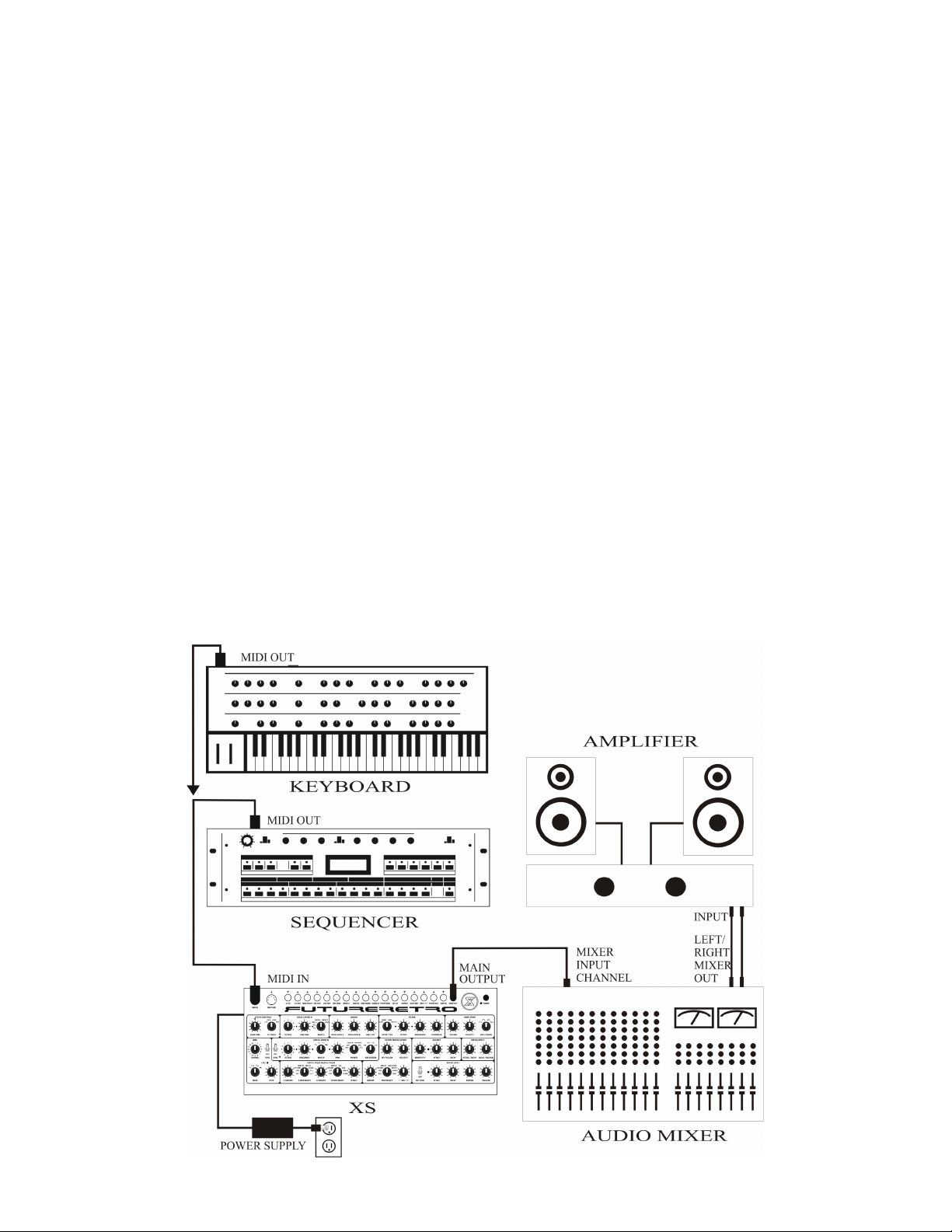
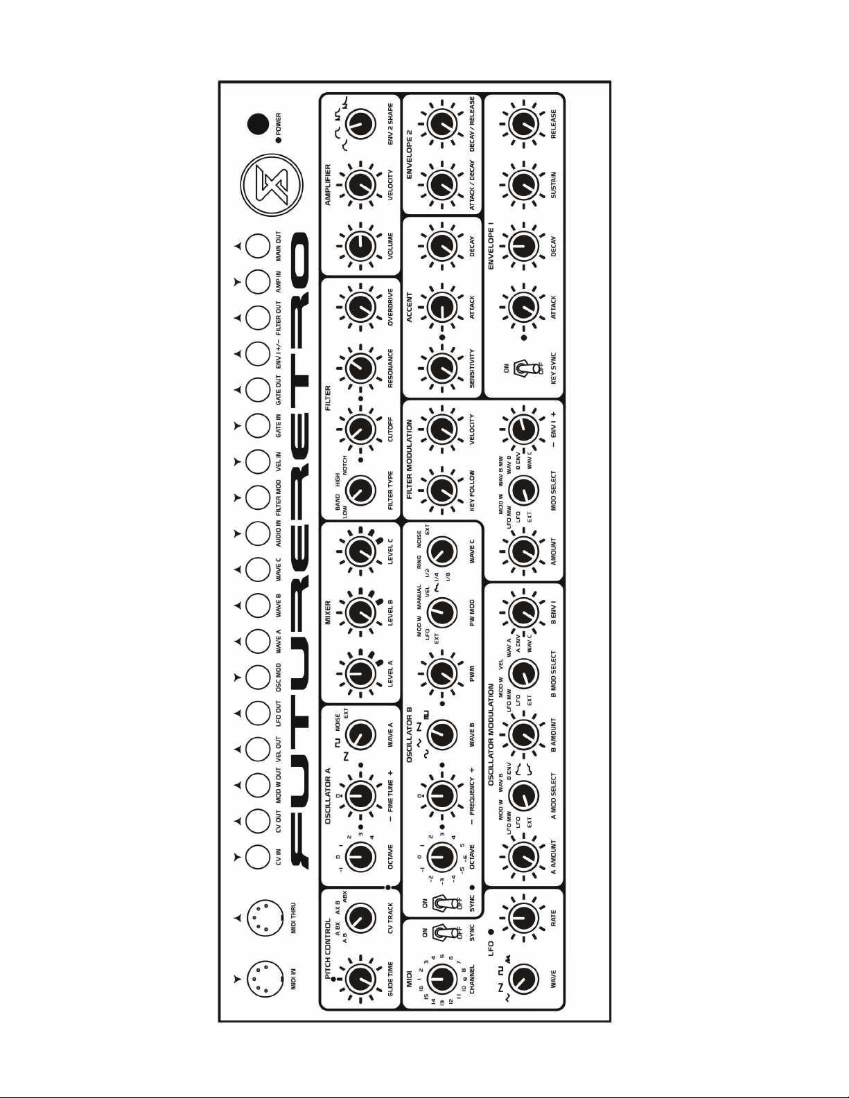
1. Connect the XS to an audio system as shown in the illustration below.
2. Connect the MIDI IN of the XS to the MIDI OUT of your controller keyboard or sequencer.
3. Set the front panel controls of the XS as shown in the illustration on page 5.
4. You’ll need to set the MIDI channel control on the XS to the same MIDI channel your
keyboard or sequencer is sending MIDI information on.
5. Press the power switch of the XS to turn the unit on, and slowly increase the volume
control on the XS to a suitable listening level (without overdriving the input of your mixer)
while you play your keyboard or sequencer.
the XS is creating.
7. When you are finished playing, press the power switch again to turn its power off.
Remember, we’re just getting started here. For a full understanding of this product and its features,
please read through the entire manual.
Note: As a general rule, first turn on the XS, then your mixer, and then your amplifier. When turning
your studio equipment off, you’ll want to turn off the amplifier first, then proceed with turning off the
rest of your equipment. This will prevent any power surges to your amplifier and speakers, which could
damage them.
Page 7
5
Page 8
6
CONNECTIONS
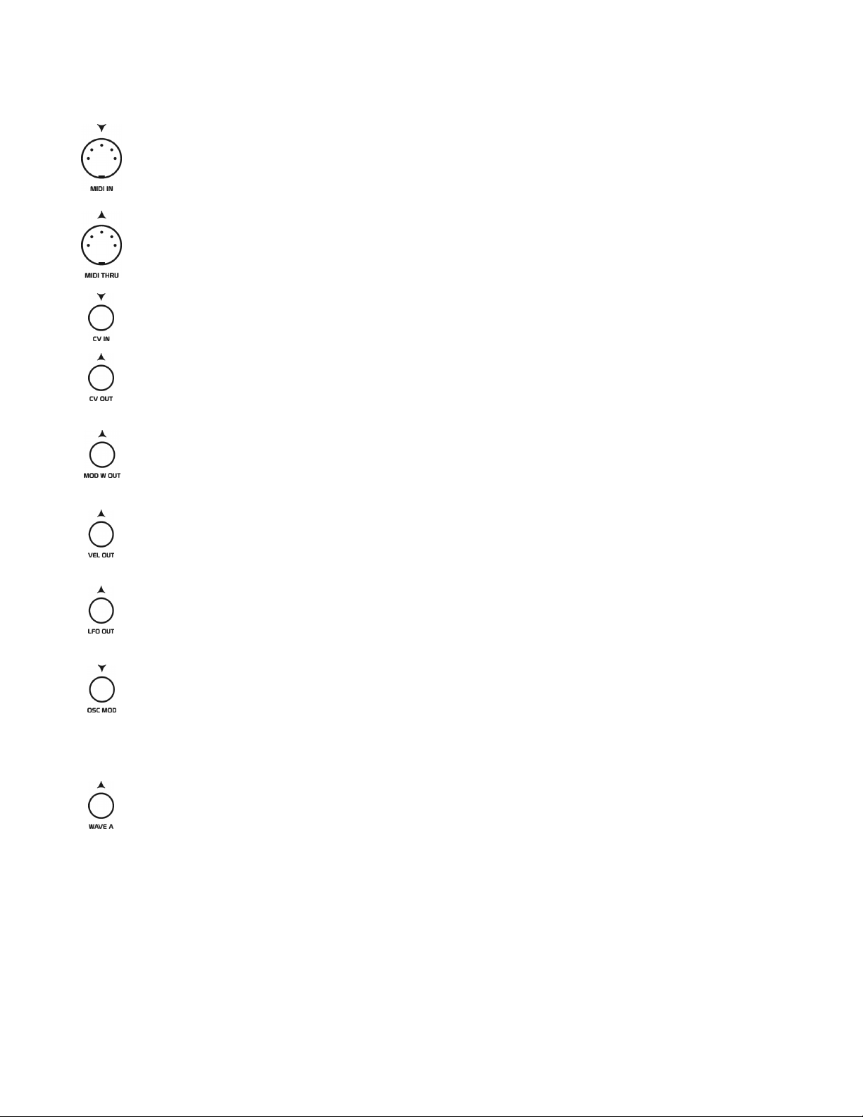
MIDI IN: Information received at the MIDI IN jack can be used to play the sounds of the XS.
Use a MIDI cable to connect this input to an external sequencer or keyboard’s MIDI OUT.
MIDI THRU: All information received at the XS MIDI IN jack will be sent out the MIDI
THRU jack. Use a MIDI cable to connect this output to another device’s MIDI input for
creating a daisy chain between multiple MIDI units.
CV IN: Connect this input to a 1V/Oct standard CV output of another device, in order to
control the pitch of the oscillators in the XS.
CV OUT: MIDI note/pitch data received at the XS MIDI IN jack will be converted to a control
voltage of the 1V/Oct standard. You can connect this CV output to the CV or modulation inputs
of any device to control the pitch of its oscillators or other circuits.
MOD W OUT: Mod Wheel data received at the MIDI IN jack will be converted to an
equivalent control voltage ranging from 0 to +10 volts. Connect this output to the CV or
modulation inputs of any device you wish to control with the mod wheel.
VEL OUT: MIDI Note/Velocity data received at the XS MIDI IN jack will be converted to an
equivalent control voltage ranging from 0 to +10 volts. Connect this output to the CV or
modulation inputs of any device you wish to control with Note Velocity.
LFO OUT: The waveform currently selected in the LFO section will be available at this output.
All LFO waveforms have a range of –5 to +5 volts. Connect this output to the CV or
modulation inputs of any device you wish to control with the LFO.
OSC MOD: This is the external modulation input for the oscillators. Connect this input to the
output of any CV or modulation source you wish to modulate the oscillators with.
The external signal can be used to modify each oscillator’s pitch individually, as well as the
pulse width modulation of Oscillator B’s square/pulse waveform. Set the Mod Select controls to
EXT for any of these three sections you wish to control with the external source.
WAVE A: This is a dual-function output of the waveform selected for Oscillator A. This is a
stereo output, although mono cables can be used here without any problem. If using a mono
cable, you can insert it all the way for the tip signal, or pull it out one notch for the ring signal.
The tip of the jack provides a continuous output of Oscillator A’s selected waveform. The ring
of the jack provides the same waveform, but the amplitude of this waveform is controlled by
Envelope 1.
Either output can be connected to the input of any other device, allowing the oscillator to act as
an audio or modulation source. The waveform’s output signal will have a range of –5 to +5
volts.
Page 9
7
CONNECTIONS
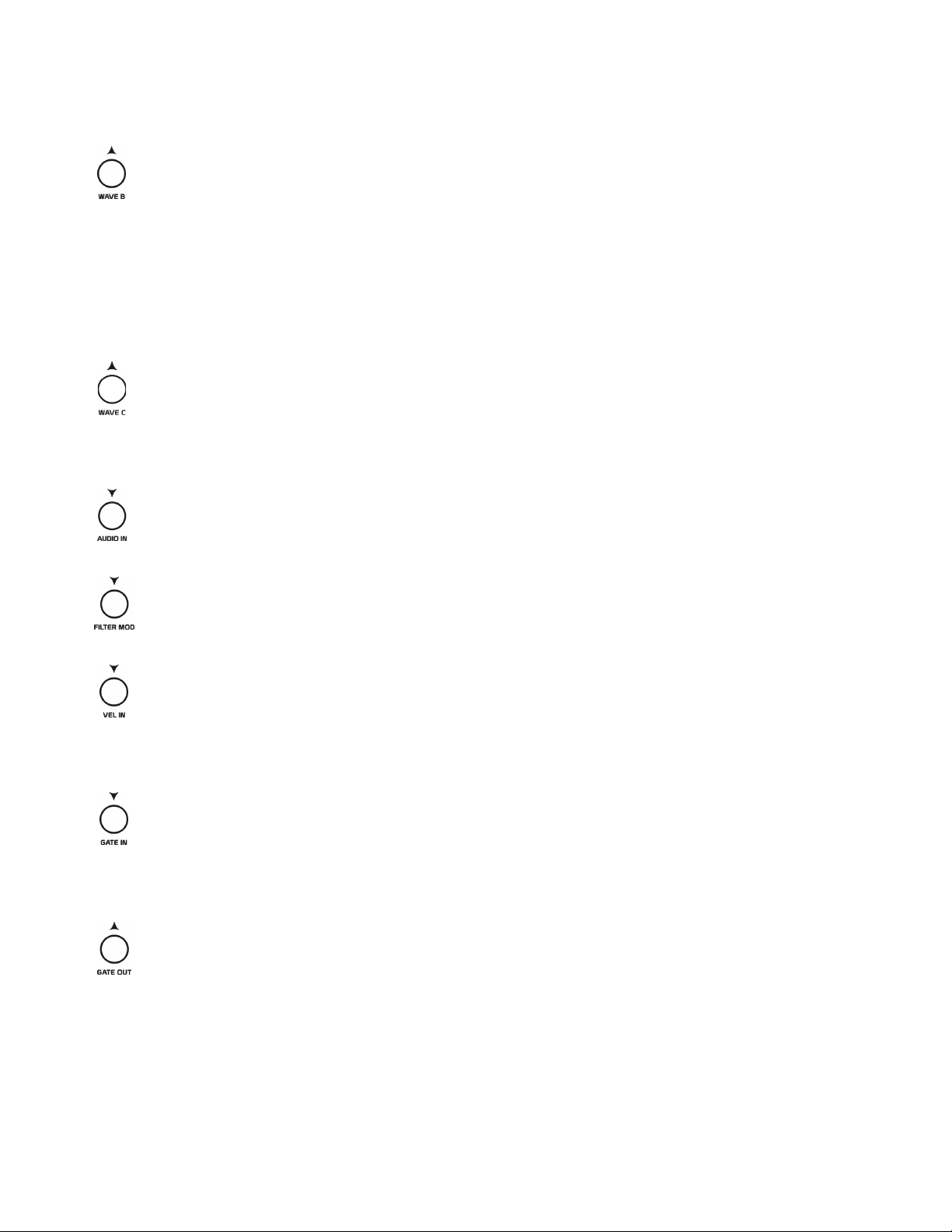
WAVE B: This is a dual-function output of the waveform selected for Oscillator B. This is a
stereo output, although mono cables can be used here without any problem. If using a mono
cable, you can insert it all the way for the tip signal or pull it out one notch for the ring signal.
The tip of the jack provides a continuous output of Oscillator B’s selected waveform. The ring
of the jack provides the same waveform, but the amplitude of this waveform is controlled by
Envelope 1.
Either output can be connected to the input of any other device allowing the oscillator to act as
an audio or modulation source. The waveform’s output signal will have a range of –5 to +5
volts.
WAVE C: This is mono output of the waveform selected for the WAVE B control. The three
sub oscillator waveforms will have a range of 0 to +15 volts, while the ring modulator and white
noise source will have a range of –5 to +5 volts.
This output can be connected to the input of any other device allowing it to act as an audio or
modulation source.
AUDIO IN: This is a mono audio input that can be connected to any line-level external audio
source output. When a cable is plugged into this jack, you can use either the WAVE A or
WAVE C control to select EXT which will select this external audio source as its waveform.
FILTER MOD: This is the external modulation input for the filter. Connect this input to the
output of any CV or modulation source you wish to modulate the filter with.
Set the Mod Select control in the filter section to EXT if you wish to use the external source.
VEL IN: This is the external Velocity input, allowing external control voltages to override the
Velocity control generated by the internal MIDI to CV converter. Generally, you will want to
connect this input to any control voltage ranging from 0 to +10 volts.
This external signal will then control all Velocity-sensitive parameters throughout the analog
section.
GATE IN: When nothing is plugged into the Gate In jack, the envelopes in the XS will be
triggered by Note On messages received via MIDI. If you connect a positive polarity gate
output of another device to the gate in of the XS, this external gate can then be used to trigger
the envelopes in the XS. Once the external gate signal reaches +1.5 volts or higher, the
envelopes will be triggered.
GATE OUT: All MIDI note message received by the XS will be converted to a positive
polarity gate ranging from 0 to +15 volts. Connect this output to the Gate In of any other device
you wish to control with gate signals.
Page 10
8
CONNECTIONS
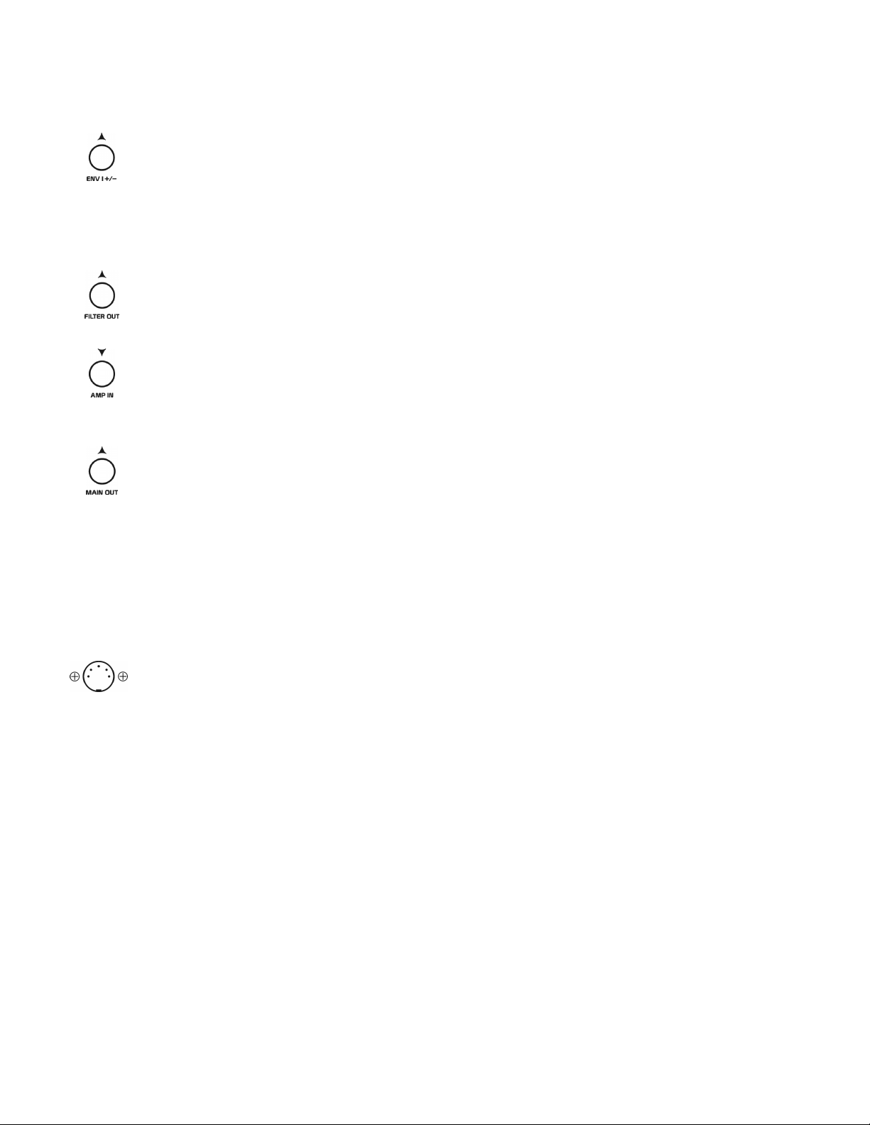
ENV 1+/-: This is a dual-function output of Envelope 1. This is a stereo output, although mono
cables can be used here without any problem. If using a mono cable, you can insert it all the
way for the tip signal or pull it out one notch for the ring signal.
The tip of the jack provides a positive polarity of Envelope 1 ranging from 0 to +10 volts. The
ring of the jack provides a reverse polarity of Envelope 1 ranging from +10 to 0 volts.
Connect either of these outputs to any modulation input you wish to control with Envelope 1.
FILTER OUT: This is the output of the Filter and Overdrive section. You can connect this
output to any audio or modulation input. The signal coming out of the filter can range from 0
volts (nothing) to +/- 15 volts, depending on the level settings in the mixer section.
AMP IN: This is the main input for the Amplifier section. When nothing is plugged into the
Amp In jack, the output of the filter will be connected to the amplifier’s input. Once a cable is
inserted into the Amp In jack, audio coming from the filter’s output is disconnected from the
amplifier, and only the external signal will be routed through the amplifier.
MAIN OUT: This is the main output of the Amplifier section. Typically, you will connect this
output to the input of your mixing console or amplifier. This output is monophonic.
Note: All 1/4” connectors are monophonic unless specified as stereo in their description.
Note: In some of the stereo jack descriptions, we state that you can pull the cable out one notch.
It may be more accurate, however, to say pull the cable out completely and then reinstall the
cable so it is just touching the first contact of the jack. If the cable were actually pulled out one
notch, it would end up shorting both tip and ring connections of the jack, which may cause
operations other than described here in the manual, though not harmful to the unit.
POWER: Use only the factory-provided power supply that came with your XS. This is a
special power supply that has multiple output voltages. Connect the mini-DIN connector of the
power supply to the power jack, located on the bottom of the unit. Connect the power mains
connector to your wall outlet. The power supply can operate on power main voltages ranging
from 90—260 volts AC, which should be compatible with most power standards worldwide.
The power cable which connects from the body of the power supply to your wall outlet can be
changed out with standard IEC type cables, which can then support the various pin
arrangements of each countries power main standards.
Page 11

9
OVERVIEW OF ANALOG SYNTHESIS
The XS is a true analog synthesizer, which is capable of producing an infinite amount of sonic textures.
All aspects of a sound can be changed instantly by the controls and switches located on the front panel.
The settings of these controls are never digitized or stored in memory. Therefore, the sound the XS
produces is always a direct representation of the actual control settings.
By keeping the controls of the XS completely analog you get infinite resolution of each parameter,
whereas digital synthesizers typically provide only 128 defined steps for each parameter. We feel that
digitizing the controls of an analog synthesizer will ultimately limit the precision that analog provides.
If you are new to synthesizers or analog synthesis, fear not. It’s actually quite easy and rewarding, to say
the least. No messy menus to fuss with, only hands-on manipulation of sound.
With a basic understanding of sound, you too can create an infinite pallette of sounds.
All sounds can be broken down into three basic elements, which are Frequency (pitch), Harmonic
Content (tone), and Amplitude (volume).
Frequency is measured in Hertz (Hz). Hz is the number of times an oscillator repeats its periodic
waveform within one second of time. For example, the range of human hearing is from approximately
20 Hz to 20,000 Hz (referred to as 20 kHz). The human ear perceives a low frequency as having a lower
pitch, and a higher frequency as having a higher pitch. The XS is capable of producing frequencies
covering the entire audible range of hearing as well as those above and below the 20 Hz to 20,000 Hz
range. The frequency that the oscillators produce in the XS can be controlled in a variety of ways that
will be discussed later in the Analog Controls section of this manual.
Harmonic Content refers to the amount of frequencies contained within a sound. The most dominant or
perceived pitch in a sound is called the fundamental frequency. All other frequencies in the sound are
harmonics of the fundamental frequency. Each harmonic is simply another sine wave at a reduced
amplitude of the fundamental frequency. Harmonics are often referred to as the 2nd, 3rd, 4th, and so on.
The number of the harmonic simply describes the number of cycles this harmonic produces for each single cycle of the fundamental frequency.
The shape of an oscillator’s waveform is relative to its harmonic content, and there are four common
waveshapes generated by a musical oscillator.
A sine wave (the one that looks like an S turned sideways), for instance, is the most basic waveform,
having only a fundamental frequency and no additional harmonics. Sine waves sound very thin and are
pure in sound.
A triangle waveform contains a fundamental frequency and all odd harmonics (3rd, 5th, 7th and so on)
of that frequency. This causes it to sound slightly fuller than a sine wave.
A square wave also contains a fundamental frequency and all odd harmonics of that frequency. The
difference between a square and a triangle waveform is that the harmonics are more pronounced in the
square wave, giving it a somewhat hollow yet fuller sound than the triangle. In the XS, the duty cycle of
this square wave can also be varied to create what is known as a pulse waveform. The width of this
pulse alters the harmonic content of the waveform. Consider the true square wave whose pulse is 1/2 the
period of the waveform. We know that the 2nd harmonic and its multiples have been eliminated, leaving
only the odd harmonics. Let’s say the pulse width is changed to 1/3 the period; this then eliminates the
3rd harmonic and its multiples such as the 6th, 9th, and 12th harmonics. A pulse width of 1/4 the period
would then eliminate the 4th, 8th, and 12th harmonics.
Page 12

10
OVERVIEW OF ANALOG SYNTHESIS
A sawtooth waveform is one of the most complex shapes, since it contains a fundamental frequency and
all harmonics of that frequency. Sawtooth waves are very full sounding and have a unique raspy quality
to them.
In addition to these four common waveshapes, there are other items which can also be used as audio
sources which will be described in more detail later on.
You can mix the waveforms of oscillators and other audio sources, together to create more complex
tones. This method is often referred to as additive synthesis.
The most common way to alter the harmonic content of a waveform, however, is by using a filter. This
is referred to as subtractive synthesis, where instead of adding more harmonics, we are actually taking
away or modifying the harmonic content of the oscillator waveforms and other audio sources.
The filter in the XS provides four filter types: lowpass, highpass, bandpass, and notch.
Each filter does just what it sounds like. With the lowpass filter, low frequencies are allowed to pass
through the filter while higher frequencies are attenuated. A highpass, on the other hand, allows the high
frequencies to pass through the filter while the lower frequencies are attenuated. The point at which
frequencies pass or are attenuated by the filter is determined by the filter’s cutoff frequency, which is
variable over the entire audio range. A bandpass filter allows only the frequencies closest to the filter’s
cutoff frequency to pass through, while attenuating all frequencies higher and lower than the cutoff
frequency. A notch filter has the opposite effect of a bandpass filter, where the harmonics closest to the
cutoff frequency are attenuated while all other harmonics are allowed to pass through the filter.
Each filter type also provides resonance, which boosts the amplitude of the frequencies closest to the
cutoff frequency of the filter. The cutoff frequency can be manually adjusted or animated by the use of
modulation sources. Modifying the harmonic content of your audio sources are key to breathing life into
your sounds and making them interesting.
Amplitude is a term used to describe the level of a waveform, or a sound’s overall volume. The volume
of traditional instruments is usually determined by how hard a surface is struck, a string is plucked, or
the force of air blown through a wind instrument. Synthesizers use amplifiers to boost and attenuate a
sound’s amplitude in a similar fashion to increasing and decreasing the volume on your stereo. All
sounds have their own unique shape of volume. This shape can be described as the envelope. The XS
provides four envelope types to help shape the amplitude of a sound. In essence, envelopes are a way of
automating the volume. The controlling envelope can be defined as having attack, decay, sustain, and
release.
When a note is played, the attack parameter determines the amount of time it takes to go from silence to
the loudest possible volume. Once the loudest volume level is reached, the decay parameter then
determines the time it takes to go from the loudest level back to silence or some other defined level.
This defined level is referred to as sustain. Once the sustain level is reached, the sound will remain at
this volume until the note is released, at which point, the release parameter will determine how long it
takes for the volume to return to silence.
The XS also uses Velocity information, which determines how soft or hard a note is played, to control
the amplitude of sounds. So when a note is played softly, the sound is quieter. And as you play harder,
the sound gets proportionally louder.
And finally, the main volume control is also used to set the overall output level for all sounds.
Pay attention to the everyday sounds all around you and consider the frequencies, harmonic content, and
amplitude it takes to create them. And before long, you too will be able to create any sound imaginable.
Page 13
11
Page 14
12
CONTROLLING YOUR XS
There are several ways to control your XS.
One way is to use MIDI (Musical Instrument Digital Interface), a standard developed to allow one
electronic instrument to talk to another using only a single 5-pin DIN cable. Nearly all modern
electronic instruments have and support MIDI.
Before MIDI was developed, the standard practice was to use control voltages and logic gate signals as a
means of controlling, modifying, and triggering electronic circuits in synthesizers.
The XS supports both standards, old and new, and even allows you to mix the use of both at the same
time. The XS also converts MIDI data it receives into control voltages and logic gate signals to control
other pre-MIDI instruments, sound modules, and other circuits.
USING MIDI
The XS responds to MIDI Note On/Off, Pitch (C2-C7), Pitch Bend, Mod Wheel, Velocity, and MIDI
Clock messages. Any MIDI instrument capable of sending this data can be used to play the XS. The
most practical way to play the XS would be to connect it to a MIDI keyboard or MIDI sequencer.
Simply connect the MIDI OUT of your keyboard or sequencer to the MIDI IN of the XS using a 5-pin
DIN MIDI cable.
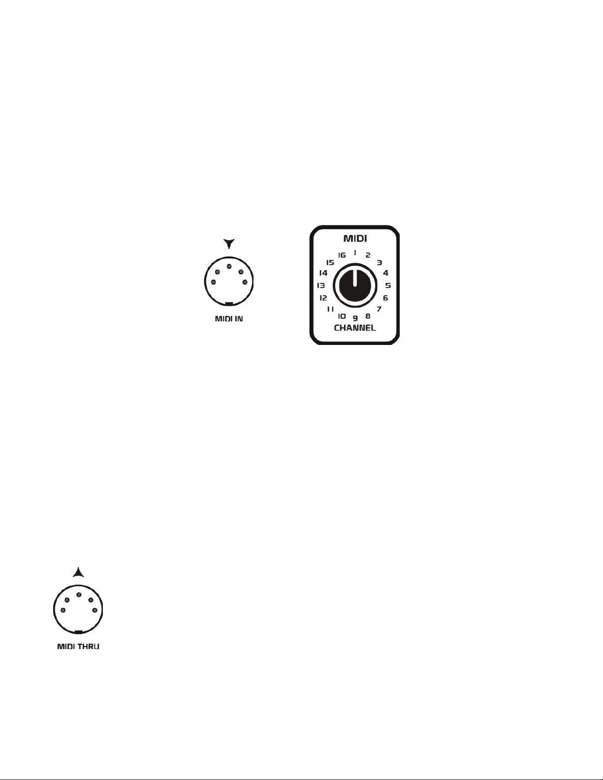
The XS can receive MIDI data on only 1 of the 16 possible MIDI channels at any time. In order for the
XS to receive MIDI data from the keyboard or sequencer, you must first set both instruments to the
same MIDI channel. Setting the MIDI channel that the XS will receive data on is done with the MIDI
Channel control. Simply rotate this control so its indicator points to the desired MIDI channel.
Note: Changing the MIDI channel selection on the XS while notes are currently being played may cause
these notes to become latched, which prevents them from turning off. Avoid changing the MIDI channel
selection while notes are being played. Should notes become latched, first stop the master device
sending MIDI data to the XS, then turn the XS off and then back on again.
If you have multiple MIDI devices in your studio that need to be controlled by your main
MIDI keyboard or sequencer, you can connect the MIDI THRU of the XS to the MIDI IN of
another device.
Using this method, all MIDI information the XS receives will be then be sent on to the other
MIDI device.
Page 15
13
CONTROLLING YOUR XS
is converted to
MIDI TO CV/GATE CONVERTER
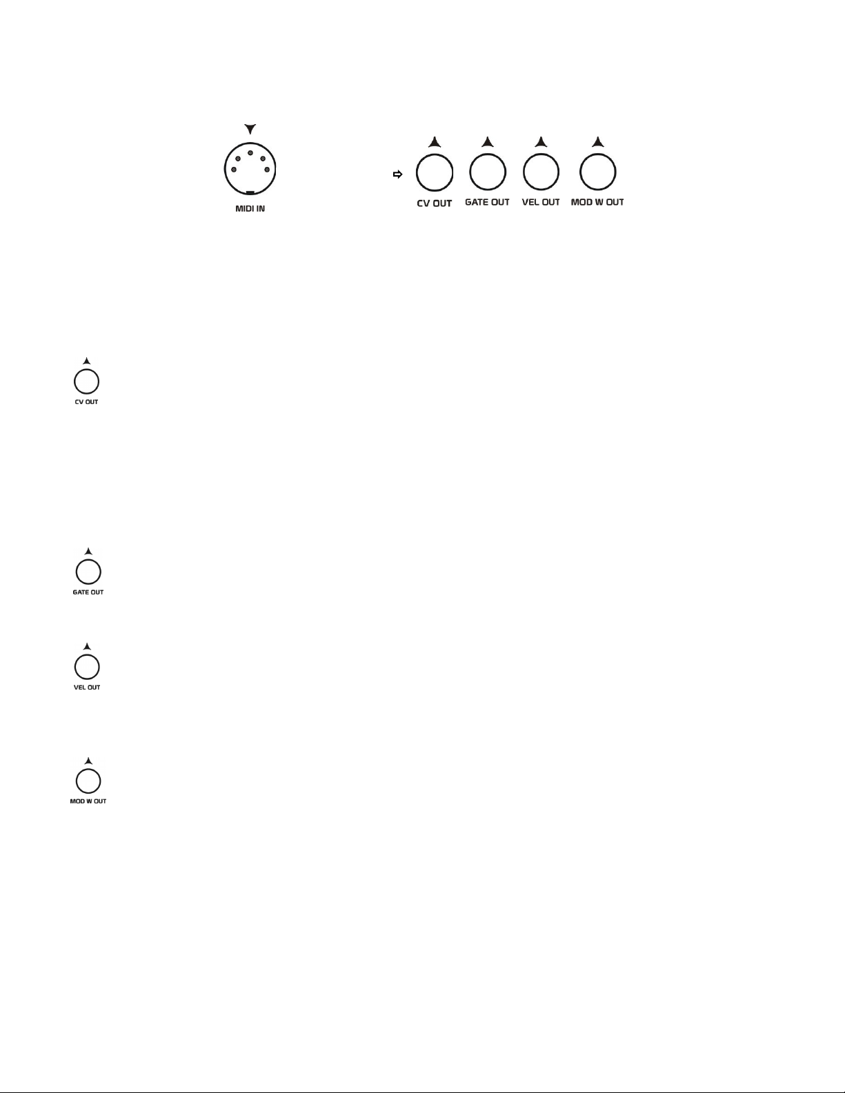
When MIDI information is received by the XS, the MIDI data is then converted into control voltages
and logic gate signals that control the internal analog sound section. These control voltages and logic
signals are also available at the 1/4” output jacks, which allows you to control other external analog
circuits.
The CV OUT signal generated represents the pitch of MIDI notes received. This control voltage
follows the 1 V/Oct (volt per octave) standard, where each semitone note equals 1/12th of a volt,
and each octave equals 1 volt. Since the XS responds to MIDI notes C2 through C7, this control
voltage can range from 0 to +5 volts.
MIDI pitch bend messages will also affect this control voltage, causing a note’s voltage to become
slightly more positive or negative than typically produced for that note.
If more than one note is played at a time by the MIDI controller, the XS will activate its internal glide
circuit which will slew the voltage from one note to another at the rate set by the Glide Time control.
This output can be used to control the pitch of oscillators, filters, or other voltage-controlled circuits.
The GATE OUT signal generated represents Note On/Off messages. When no notes are being
played, this logic signal will output 0 volts. When a notes is being played, this logic signal will
output approximately +14 volts.
This output can be used to trigger envelope generators or circuits with other logic inputs.
The VEL OUT signal generated represents the Velocity of MIDI notes received. This control
voltage can range from 0 to +10 volts respectively, so notes with a higher Velocity value generate
higher voltages.
This control voltage is generally used to affect the volume of sound by controlling an amplifier, but
could also be used to affect a filter’s cutoff frequency or any other voltage-controlled circuit.
The MOD W OUT signal generated represents any MIDI Mod Wheel messages received. This
control voltage can range from 0 to +10 volts respectively, so as you increase the mod wheel
amount this voltage increases.
This control voltage is generally used to add expression to a sound, by assigning it to modify various
parameters within a synthesizer.
TIP: You can use this MOD W control voltage as a way to animate and record parameter value changes
in a sequencer. Let’s say you assign the MOD W control to a filter’s cutoff frequency. You have a
sequence playing notes already, and now you wish to record some tweaks to the filter cutoff. Simply
move the mod wheel of your master MIDI controller, and record this data into your sequencer.
Page 16
14
CONTROLLING YOUR XS
USING CV/GATE CONTROL SIGNALS
External control voltage and logic gate signals can be used at any time in any combination to control the
XS, even while MIDI note data is being received. Receiving MIDI data is the default way to play the
XS. But when an analog voltage or gate signal is inserted into one of the control inputs it can either be
selected to modulate a specific parameter, or in some cases will automatically override the control signal
being generated by the internal MIDI to CV/Gate converter.
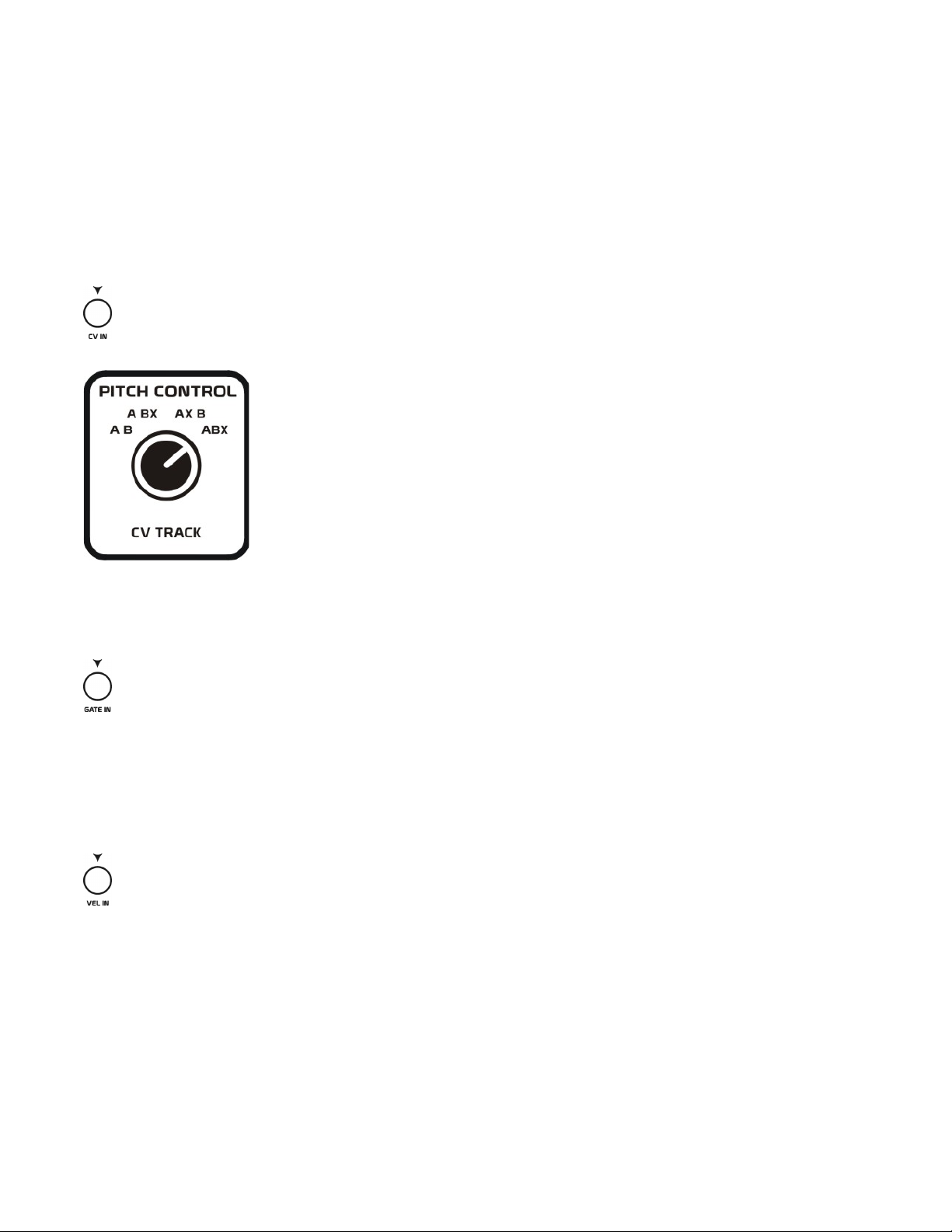
The CV IN input is routed to the CV Track control in the PITCH CONTROL section. This control
determines which source Oscillator A and B will use to control their pitch.
In the A B position, both oscillators will be controlled by MIDI notes received.
In the A BX position, Oscillator A will respond to MIDI notes received, while
Oscillator B will be controlled by an external voltage inserted into the CV IN
jack.
In the AX B position, Oscillator A will be controlled by an external voltage
inserted into the CV IN jack, while Oscillator B will be controlled by MIDI notes
received.
In the ABX position, both oscillators will be controlled by an external voltage
inserted into the CV IN jack.
Note: If no signal is inserted into the CV IN jack, and one or both of the oscillators are selected to use
the external voltage, these oscillators will produce a stationary pitch, which can be useful for certain
effects.
The GATE IN input is used to trigger the internal envelope circuits. Any time a cable is inserted
into this jack, it will override MIDI triggering of the envelopes. Typically, you will want to use any
logic gate signal ranging from 0 to +15 volts. Any voltage received higher than +1.5 volts will be considered as a Gate On, and any voltage less will be considered as a Gate Off. This input can also accept
negative voltages without harming the unit, but if they do not exceed the +1.5 volt trip level, no gate will
be produced.
TIP: With a trip point of +1.5 volts, you can also use audio signals to trigger the envelopes in the XS.
The VEL IN input is used to control the amplitude of both envelopes (depending on the velocity
amount setting used for each), and can also be used to directly modify the pitch of Oscillator B and
the pulse width duration of its square/pulse wave. Any time a cable is inserted into this jack, it will
override the MIDI Velocity control voltages being generated to control these parameters. Typically, you
will want to use any control voltage ranging from 0 to +10 volts as the VEL IN source, although input
voltages can range from –15 to +15 volts without harming the unit.
TIP: Using Velocity control signals that swing both positive and negative can have interesting results.
For instance, if the Velocity input goes negative and is controlling Envelope 1’s amplitude, it will cause
the output of this envelope to become inverted. However, negative control voltages applied to Envelope
2 (the amplifier) will not allow the amplifier to pass audio to the output during the negative period. If
you do not desire this effect on the amplifier, simply turn down the Velocity control for the amplifier.
Page 17
15
ANALOG CONTROLS
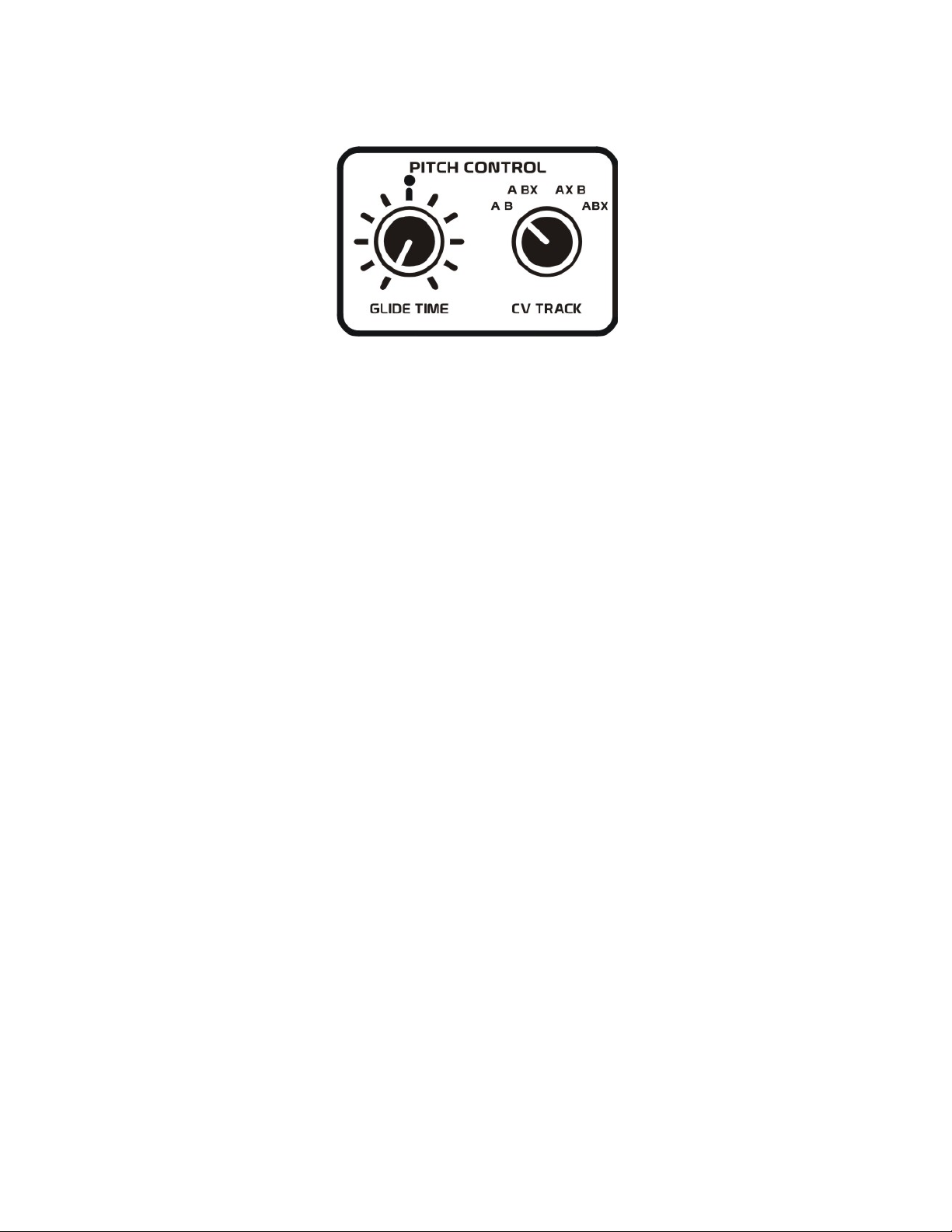
PITCH CONTROL
This section determines how the pitch control voltage affects the oscillators.
GLIDE TIME: If more than one note is played at a time by a MIDI controller or sequencer connected to
the MIDI input of the XS, the XS will activate its internal glide circuit which will slew the voltage from
one note to another at the rate set by this control. With this control rotated fully counter-clockwise, the
glide time from one pitch to another will be instant, with no apparent slewing of pitch. The glide time
will increase as you rotate this control in the clockwise direction.
CV TRACK: This control determines which source each oscillator will use to control its pitch.
In the A B position, both oscillators will be controlled by MIDI notes received.
In the A BX position, Oscillator A will respond to MIDI notes received, while
Oscillator B will be controlled by an external voltage inserted into the CV IN jack.
In the AX B position, Oscillator A will be controlled by an external voltage
inserted into the CV IN jack, while Oscillator B will be controlled by MIDI notes
received.
In the ABX position, both oscillators will be controlled by an external voltage
inserted into the CV IN jack.
Note: If no signal is inserted into the CV IN jack, and one or both of the oscillators are selected to use
the external control voltage, these oscillators will produce a stationary pitch that can be useful for
certain effects.
Page 18
16
ANALOG CONTROLS
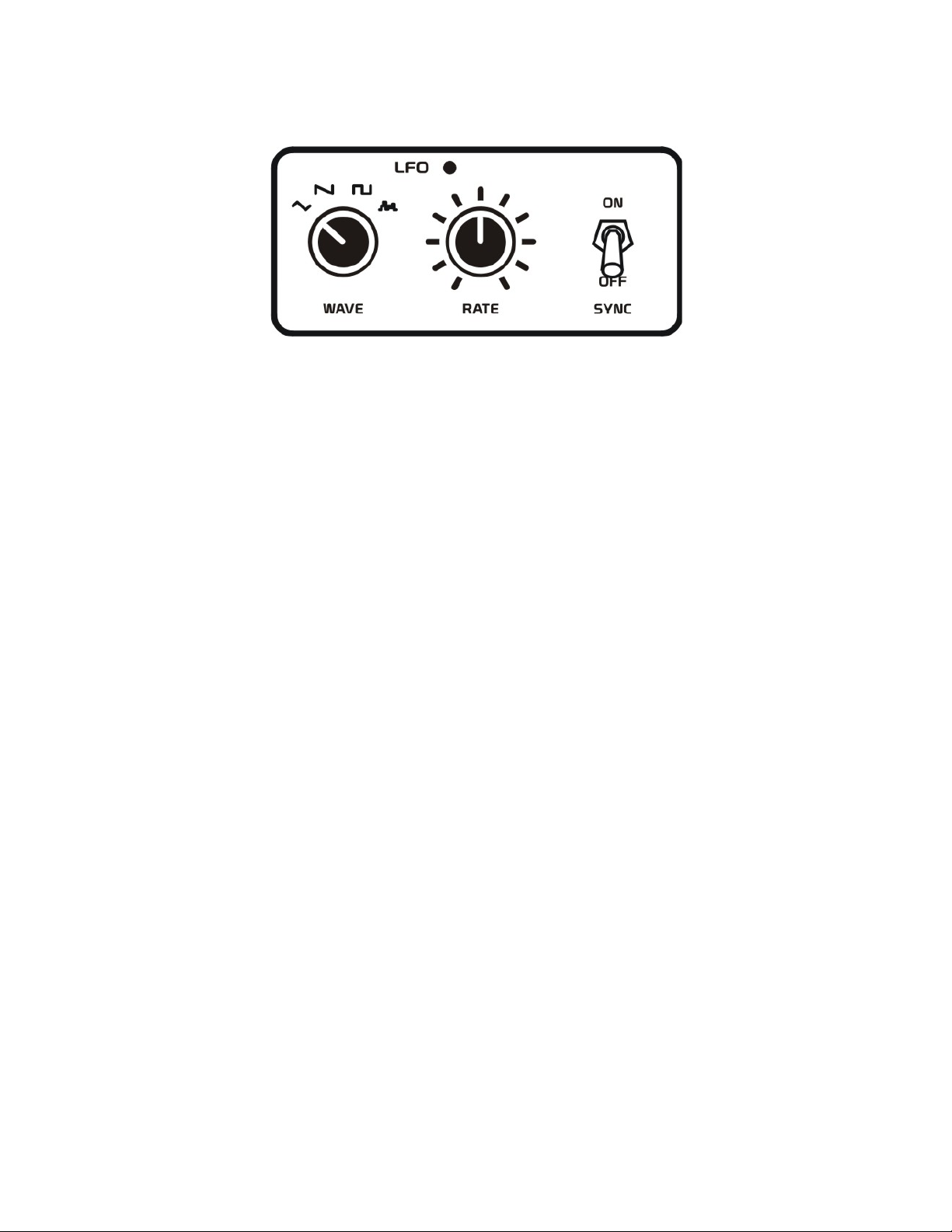
LOW FREQUENCY OSCILLATOR
A low frequency oscillator (LFO), is a modulation source whose frequency is generally below the range
of human hearing. The LFO provides multiple waveshapes and a variable rate at which it can modify
other parameters of a synthesizer. Common uses would be to add vibrato or tremolo to a sound, or to
create slowly evolving sweeps or changes to parameter settings.
WAVE: This control selects one of four waveforms for the LFO, including triangle, sawtooth, square,
and random shapes.
The TRIANGLE waveform provides a smooth linear rising/falling waveform, which is ideal for vibrato
and tremolo effects.
The SAWTOOTH waveform provides a smooth linear falling waveform with a quickly rising edge. The
effect of this waveform is similar to a decaying envelope with a fast attack.
The SQUARE waveform has only two possible states: high or low. This may be useful for creating trill
effects. In addition, the square waveform may also be used as a logical gate signal for triggering other
circuits such as envelope generators, analog sequencers, or arpeggiators.
The RANDOM waveform will produce varying amplitudes of voltages at a rate which is once per every
period of the other LFO waveshapes. This is useful when you wish to create sounds which are rather
unpredictable, having parameters jump around to various settings.
RATE: The RATE control determines the frequency at which the LFO will produce its waveform.
This control has two different modes of operation that are determined by the LFO SYNC switch.
When the LFO SYNC switch is in the OFF position, the LFO will be free running at variable rates from
4 seconds to 18 Hz. Rotate this control counter-clockwise for slower LFO rates, and clockwise for faster
LFO rates. The LFO LED will flash on and off at the rate of oscillation.
When the LFO SYNC switch is in the ON position, the LFO will generate its waveform at defined
divisions of a MIDI clock. There are 16 MIDI clock divisions in all, including 8 bars, 4 bars, 2 bars, 1
bar, 1/2, 3/8, 1/3, 1/4, 3/16, 1/6, 1/8, 3/32, 1/12, 1/16, 1/24, and 1/32 notes divisions.
In order to use the LFO MIDI SYNC function, make sure you have a MIDI sequencer or other MIDI
clock source’s MIDI OUT connected to the MIDI IN jack of the XS. You’ll need to set up your MIDI
sequencer to send MIDI clock/start/stop messages. When you first set the LFO SYNC switch to ON,
your sequencer needs to send a MIDI start command in order for the LFO to start syncing. Adjusting the
LFO’s rate while the LFO is syncing can cause the LFO waveform to become out of phase. To resync
the phase of the LFO waveform, simply send a new MIDI start message from your sequencer.
Page 19
17
ANALOG CONTROLS
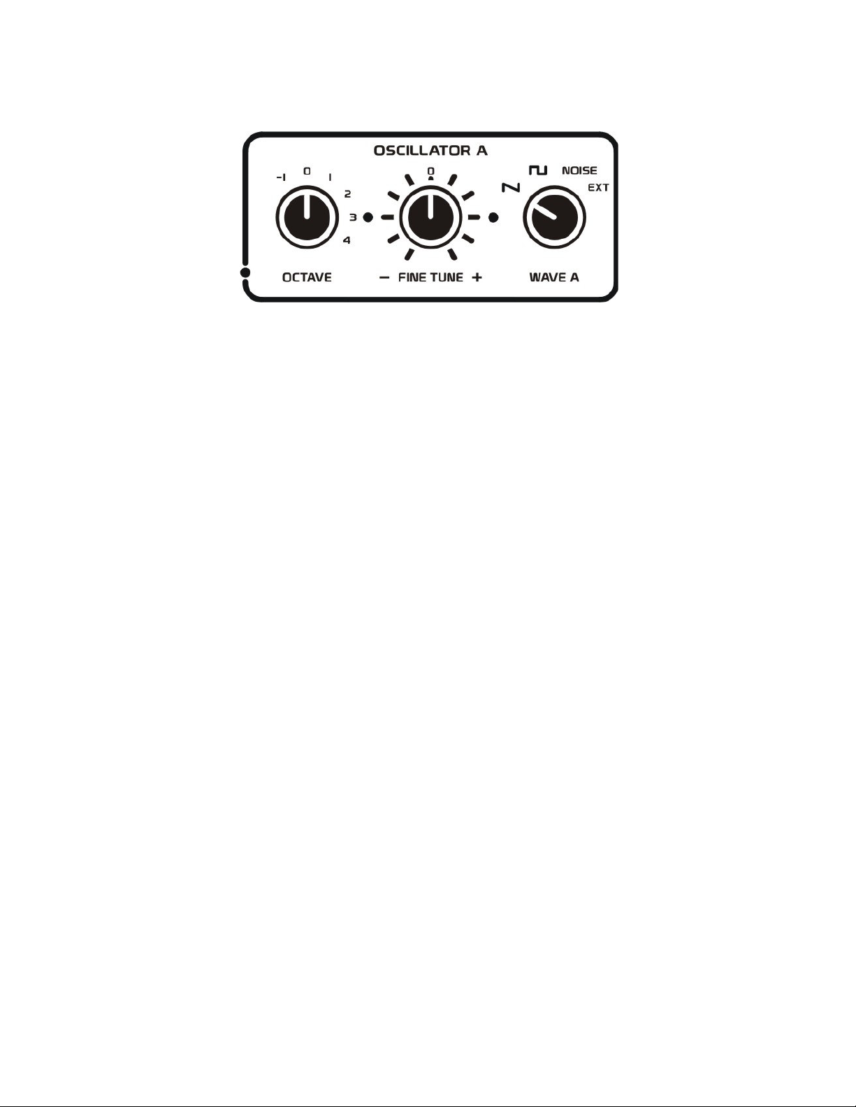
OSCILLATOR A
Oscillator A is one of the main audio sources in the XS, although it can also be used as a modulation
source. This is a wide range, ultra-stable oscillator capable of generating frequencies from
approximately 0.5 Hz to more than 100 kHz.
OCTAVE: This control is used to transpose Oscillator A through its different ranges. Zero is the default
setting for this control. If we were to play note C2 on a MIDI keyboard and switch through the different
octave ranges, we would find that the –1 setting produces 16.352 Hz, the 0 setting produces 32.703 Hz,
the 1 setting produces 65.406 Hz, the 2 setting produces 130.81 Hz, the 3 setting produces 261.63 Hz,
and the 4 setting produces 523.25 Hz. If we were to leave this octave setting in the 4 position, and play
our highest MIDI note C7, we would find that this oscillator produces a frequency of 16,744.04 Hz or
16.74 kHz. As you can see, using just this octave control and a 5-octave keyboard, we can cover the
frequency range of 16 Hz to 16 kHz. We will discuss later in the manual how to access this oscillator’s
full range.
NOTE: When using an external control voltage to control the oscillator, MIDI note C2 = 0 volts,
C3 = +1 volt, C4 = +2 volts, C5 = +3 volts, C6 = +4 volts, and C7 = +5 volts.
Therefore, with an octave setting of 0, if we input 0 volts into the CV IN jack, Oscillator A will produce a
frequency of 32.703 Hz. If the CV IN voltage changes to +5 volts with the octave control changed to 4,
Oscillator A will then produce a frequency of 16.74 kHz.
FINE TUNE +/-: This is the master fine tune control for both Oscillators A and B. When this control is
set to its mid position marked with a “0” both oscillators should be in tune. This control covers a range
of approximately 12 cents total, providing us with –6 to +6 cents in detuning. Rotating this control
counter clockwise of the “0” mark will cause both oscillators to sound flat. Rotating this control
clockwise of the “0” mark will cause both oscillators to sound sharp. You can use this control to match
the pitch of the internal oscillators to an external reference if they are slightly out of tune with one
another.
WAVE A: This control selects which waveshape will be used for Oscillator A. Although Oscillator A
actually only generates the sawtooth and square waveforms which will track the playing of notes up and
down a keyboard.
The SAWTOOTH setting selects Oscillator A’s sawtooth waveform.
The SQUARE setting selects Oscillator A’s square waveform, which has a 50% duty cycle.
The NOISE setting will select the internal white noise source, which contains an even amount of
frequencies throughout the audio spectrum.
The EXT setting will select any external audio source that is inserted into the AUDIO IN jack.
Page 20
18
ANALOG CONTROLS
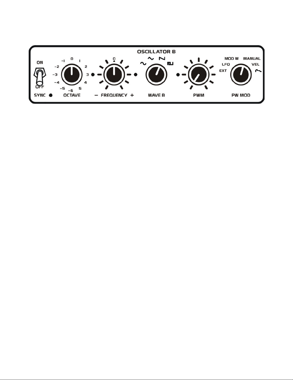
OSCILLATOR B
Oscillator B is similar to Oscillator A in that it can be an audio source or a modulation source. This is a
wide range, ultra-stable oscillator capable of generating frequencies from approximately 0.5 Hz to more
than 100 kHz.
SYNC: Oscillator B has the ability to sync its waveform to the pitch that Oscillator A is producing.
When this SYNC switch is in the ON position, every time Oscillator A’s waveform goes through a
positive transition (once every periodic cycle), it will force Oscillator B to start regenerating its
waveform shape. This then will cause Oscillator B to start introducing new harmonics in each of its
waveforms. In order to really hear this sync effect, however, you will want to make sure the frequency
of Oscillator B is always higher than that set for Oscillator A. When the SYNC switch is set to the OFF
position, Oscillator B will produce its four waveforms with their original harmonic content.
OCTAVE: This control is used to transpose Oscillator B through its different ranges. Zero is the default
setting for this control. If we were to play note C2 on a MIDI keyboard and switch through the different
octave ranges we would find that the –1 setting produces 16.352 Hz, the 0 setting produces 32.703 Hz,
the 1 setting produces 65.406 Hz, the 2 setting produces 130.81 Hz, the 3 setting produces 261.63 Hz,
the 4 setting produces 523.25 Hz, and the 5 setting produces 1,046.5 Hz. If we were to leave this octave
control in the 5 setting, and play our highest MIDI note C7, we would find that this oscillator produces a
frequency of 33,488.08 Hz or 33.48 kHz. As you can see, using just this octave control and a 5-octave
keyboard, we can cover the frequency range of 16 Hz to 33 kHz. Octave settings from –2 to –6 will
cause Oscillator B to generate frequencies below the audio range (as low as 0.5 Hz in frequency, or 2
seconds of time) when C2 is played on a MIDI keyboard. This is useful when using Oscillator B as a
modulation source. In this way, Oscillator B acts more like a second LFO in the XS. The benefit of
using Oscillator B as an LFO is that its frequency can either be stationary or can track pitches played on
a keyboard.
Remember, the CV Track control in the PITCH CONTROL section can be used to determine whether
Oscillator B’s frequency will track notes played on a keyboard or remain at a stationary frequency.
NOTE: When using an external control voltage to control the oscillator, MIDI note C2 = 0 volts,
C3 = +1 volt, C4 = +2 volts, C5 = +3 volts, C6 = +4 volts, and C7 = +5 volts.
Therefore, with an octave setting of 0, if we input 0 volts into the CV IN jack, Oscillator B will produce a
frequency of 32.703 Hz. If the CV IN voltage changes to +5 volts with the octave control changed to 5,
Oscillator B will then produce a frequency of 33.48 kHz.
Page 21
19
ANALOG CONTROLS
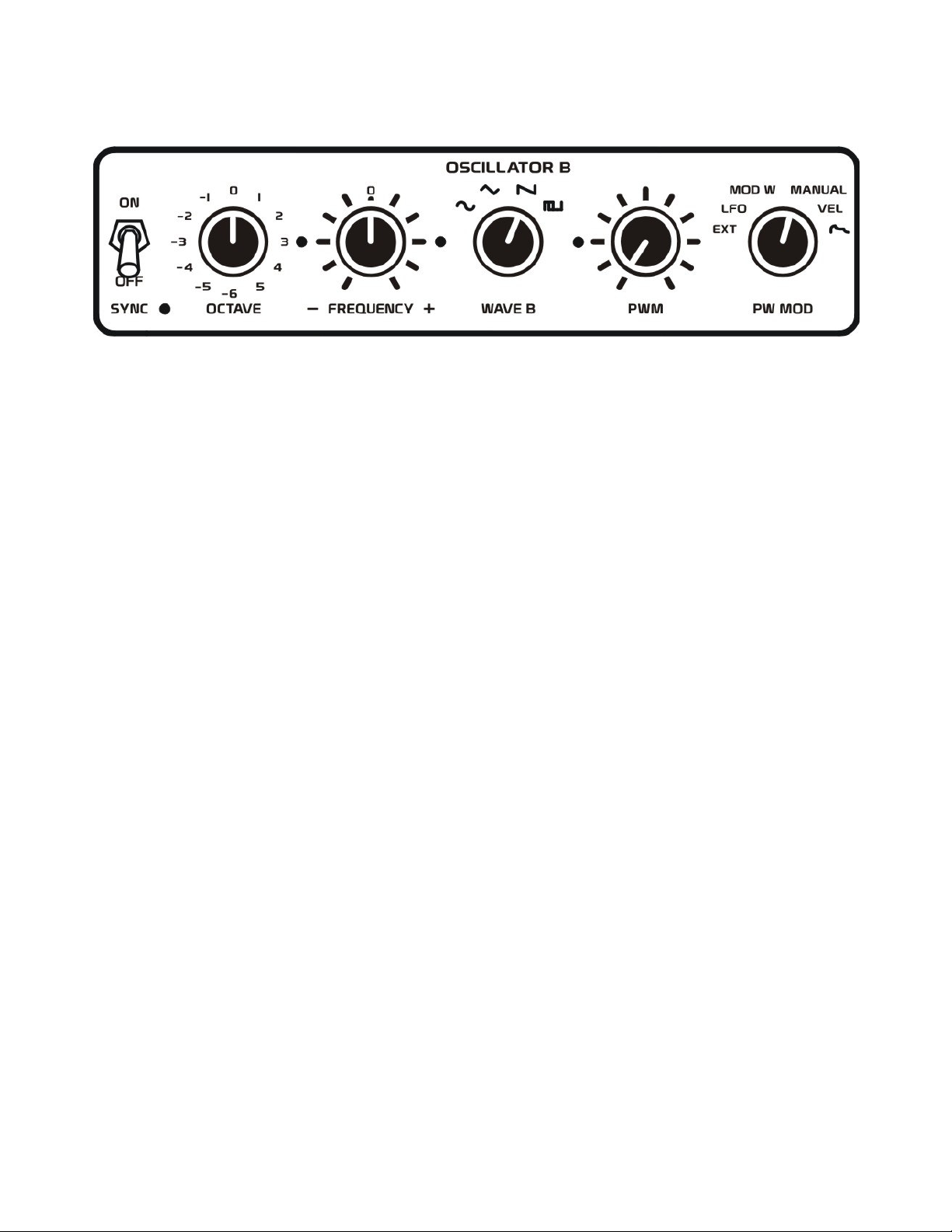
FREQUENCY +/-: This control allows Oscillator B’s frequency to be offset approximately –9 to +9
semitones from Oscillator A. When this control is set to its mid position marked with a “0”, Oscillator B
should be in tune with Oscillator A (as long as nothing is selected to modulate the frequency of either
oscillator). Rotating this control counter clockwise of the “0” mark will decrease Oscillator B’s
frequency. Rotating this control clockwise of the “0” mark will increase Oscillator B’s frequency. You
can use this control to create everything from slight oscillator detuning for that “phat” chorus/flanging
sound, or also to create chord intervals between each oscillator.
WAVE B: This control selects which waveshape will be used for Oscillator B. As you can see Oscillator
B generates four waveshapes being the sine, triangle, sawtooth, and square/pulse waveforms.
A SINE wave (the one that looks like an S turned sideways) is the most basic waveform, having only a
fundamental frequency and no additional harmonics. Sine waves sound very thin and are pure in sound.
A TRIANGLE waveform contains a fundamental frequency and all odd harmonics (3rd, 5th, 7th, and so
on) of that frequency. This causes it to sound slightly fuller than a sine wave.
The SAWTOOTH waveform is one of the most complex shapes, which contains a fundamental
frequency and all harmonics of that frequency. Sawtooth waves are very full sounding and have a
unique raspy quality to them.
A SQUARE wave also contains a fundamental frequency and all odd harmonics of that frequency; the
difference between it and a triangle waveform is that the harmonics are more pronounced in the square
wave, giving it a somewhat hollow yet fuller sound than the triangle. In the XS, the duty cycle of this
square wave can also be varied to create what is known as a square/pulse waveform. The width of this
pulse alters the harmonic content of the waveform, and this is determined by the PWM control.
Consider the true square wave whose pulse is 1/2 the period of the waveform. We know that the 2nd
harmonic and its multiples have been eliminated leaving only the odd harmonics. Let’s say the pulse
width is changed to 1/3 the period, which then eliminates the 3rd harmonic and its multiples such as the
6th, 9th, and 12th harmonics. A pulse width of 1/4 the period would then eliminate the 4th, 8th, and 12th
harmonics.
Page 22
20
ANALOG CONTROLS
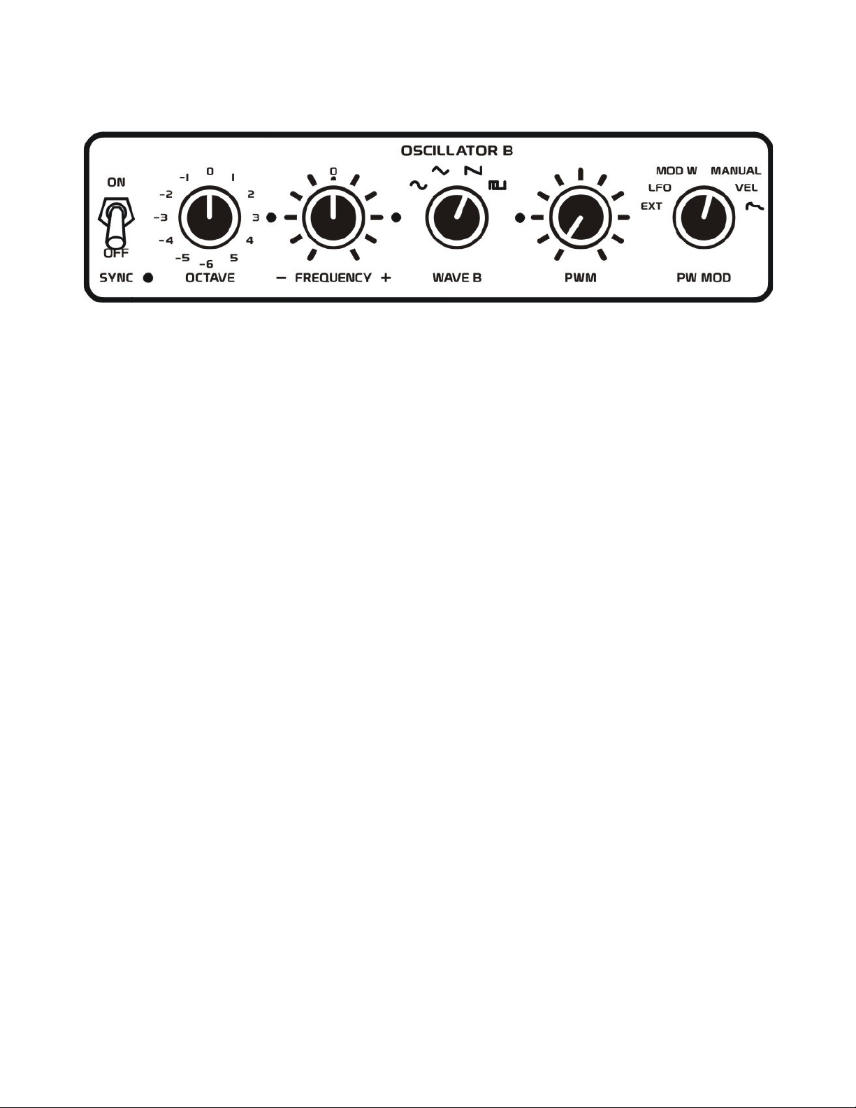
PULSE WIDTH MODULATION AMOUNT: The PWM control sets the amount of modulation that the
PW MOD source will have on Oscillator B’s square/pulse waveform. When this control is rotated fully
counter-clockwise, no modulation of the square/pulse wave will occur producing a true square wave. As
you rotate this control clockwise, the affect of modulation will increase, causing the square wave to
narrow its pulse width duration.
All of the modulation sources pre-wired in the PW MOD control will have a range of 0 to +10 volts.
This allows these sources to vary the pulse width duration from 50% duty cycle to 3% duty cycle.
When the modulation source is 0 volts a true square wave will be produced. As the modulation source
voltage becomes more positive (up to +10 volts) the pulse width duration will decrease. The exception
here is that an external modulation source that goes in the negative voltage range could also be used,
causing this pulse width duration to increase its duty cycle. The useable range for these external
modulation sources would be –10 to +10 volts.
PULSE WIDTH MODULATION SOURCE: The PW MOD control selects which modulation source
will be used to alter the pulse width duration of Oscillator B’s square/pulse wave. A control voltage
source that varies its voltage over time can be used to animate the harmonic content of the square/pulse
waveform.
In the EXT position, any external control voltage connected to the OSC MOD input jack can be used to
modulate the pulse width. Keep in mind that the useful range for this external control voltage would be
–10 to +10 volts.
The LFO setting will route the internal LFO to modulate the pulse width duration.
The MOD W setting will route the mod wheel messages from a MIDI keyboard to modulate the pulse
width duration.
The MANUAL setting is an internal +10 volt stationary reference. When this is selected, the PWM
control is used to manually adjust the pulse width duration.
The VEL setting will route Velocity messages from a MIDI keyboard to modulate the pulse width
duration. The exception here is that if an external control voltage is inserted into the VEL IN jack, this
external control voltage will override Velocity messages received from the MIDI keyboard.
The ENVELOPE setting selects Envelope 1 to modulate the pulse width duration.
Page 23
21
ANALOG CONTROLS
WAVE C
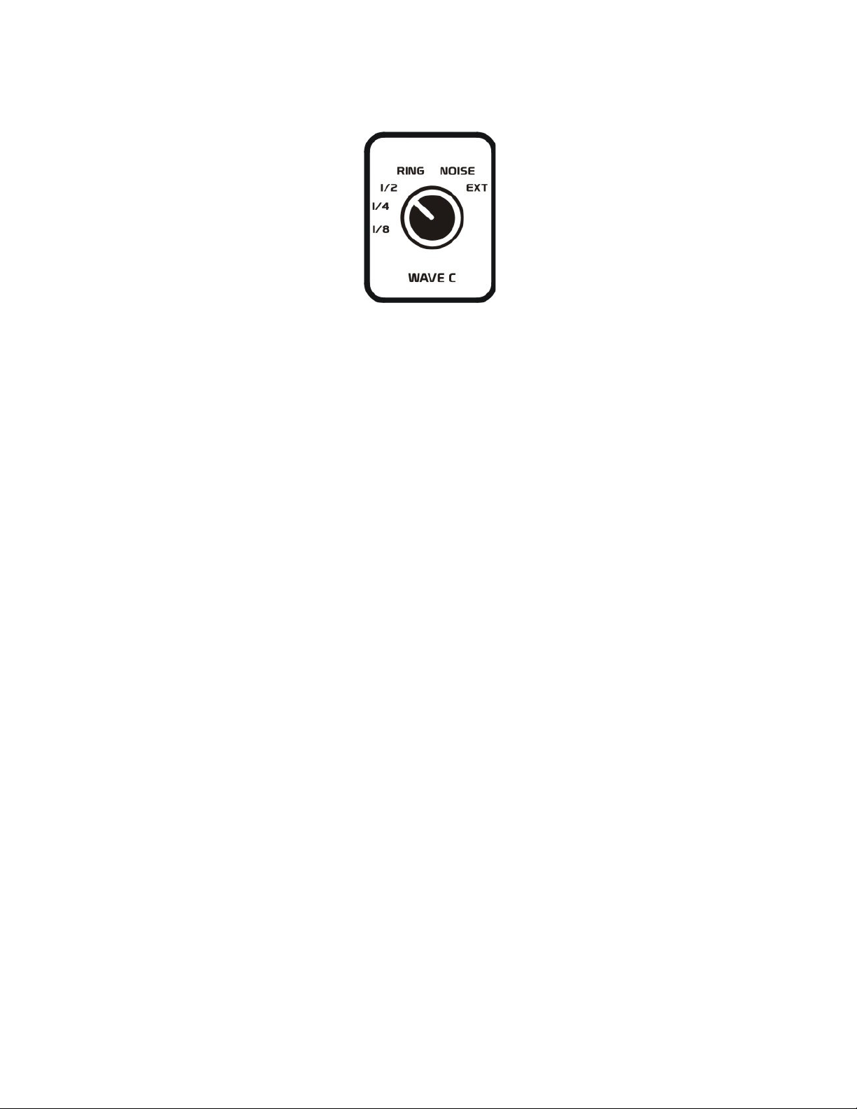
Wave C can be used as an audio source or a modulation source. Consider this more of an accessory
module to Oscillator A and B. This control provides three sub oscillators, a ring modulator, white noise
source, and access to any external audio source.
The 1/8 setting will select a square wave sub oscillator, which will be one eighth the frequency
(or 3 octave below) the frequency of Oscillator B.
The 1/4 setting will select a square wave sub oscillator, which will be one fourth the frequency
(or 2 octave below) the frequency of Oscillator B.
The 1/2 setting will select a square wave sub oscillator, which will be half the frequency (or 1 octave
below) the frequency of Oscillator B.
TIP: Modulating the frequency of Oscillator B, can also affect the frequency of these sub oscillator
waveforms. The result can sometimes sound like the sub oscillators are syncing their frequencies,
jumping from one tone to another for interesting results.
The RING setting will select the output of the ring modulator. A ring modulator takes two different
input signals, determines the sum and difference of their frequencies, and outputs the results to create
new harmonic combinations. By default one input of the ring modulator is determined by the waveform
selected with the WAVE A control for Oscillator A. The other input of the ring modulator is determined
by the waveform selected with the WAVE B control for Oscillator B. If you wish to ring modulate an
external audio signal, insert it into the AUDIO IN jack, select EXT with the WAVE A control, and
select the modulation waveform with the WAVE B control.
TIP: Ring modulating an external audio source such as a person talking can add sci-fi like effects to the
voice. Try using the sine wave for Oscillator B as the modulation source, which will be more transparent, and play Oscillator B up and down the keyboard range to create pseudo pitch-shifting effects.
The NOISE setting will select the internal white noise source, which contains an even amount of
frequencies throughout the audio spectrum.
The EXT setting will select any external audio source which is inserted into the AUDIO IN jack.
Page 24
22
ANALOG CONTROLS
OSCILLATOR MODULATION
The oscillator modulation section is used to route internal and external modulation sources to modify the
frequency of Oscillators A and B. With these sources one can create numerous effects such as vibrato,
FM, cross-modulation, self-modulation, pitch sweeping, and more. When oscillators are modulated with
an audio range source, this FM effect can alter a waveforms harmonic content quite drastically for new
timbral possibilities.
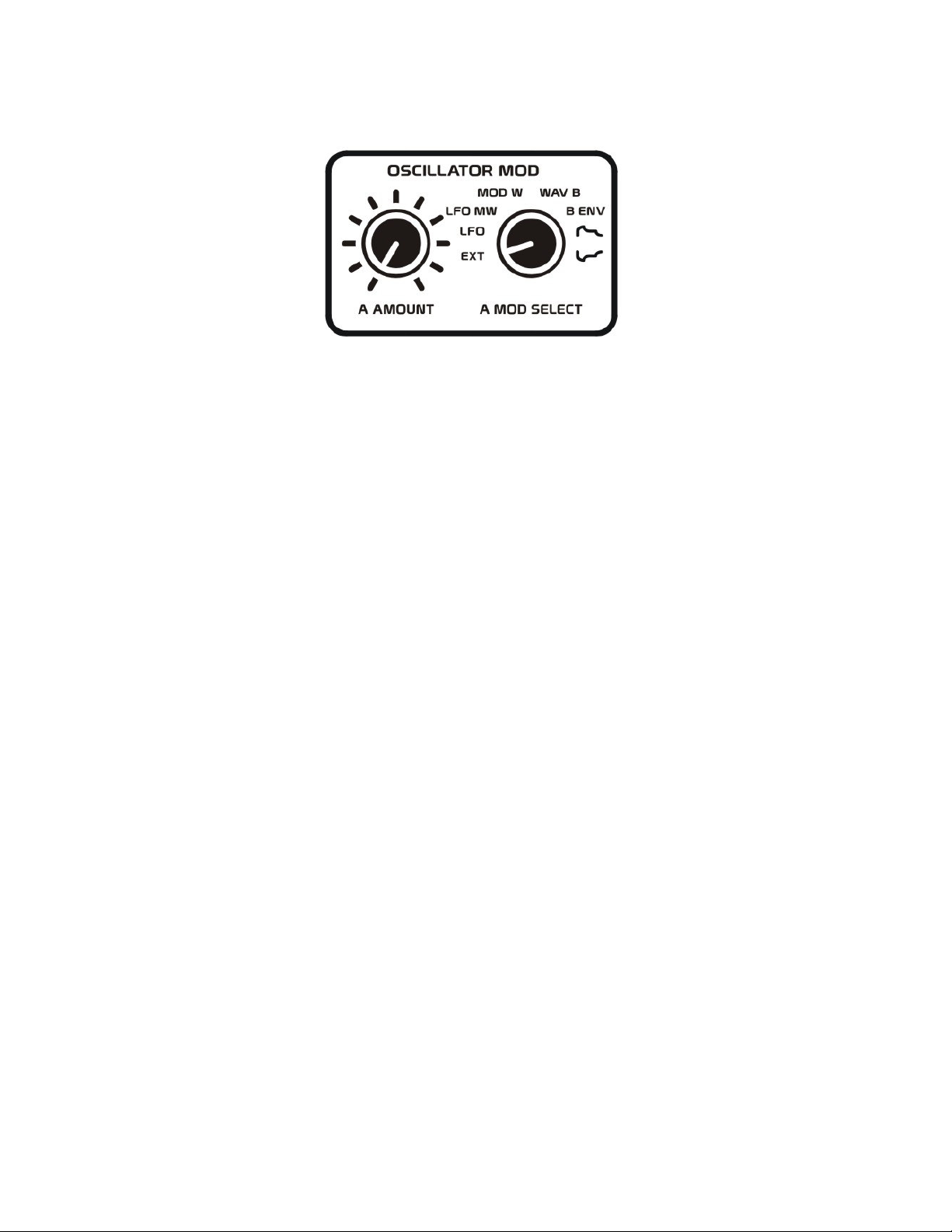
OSCILLATOR A MODULATION
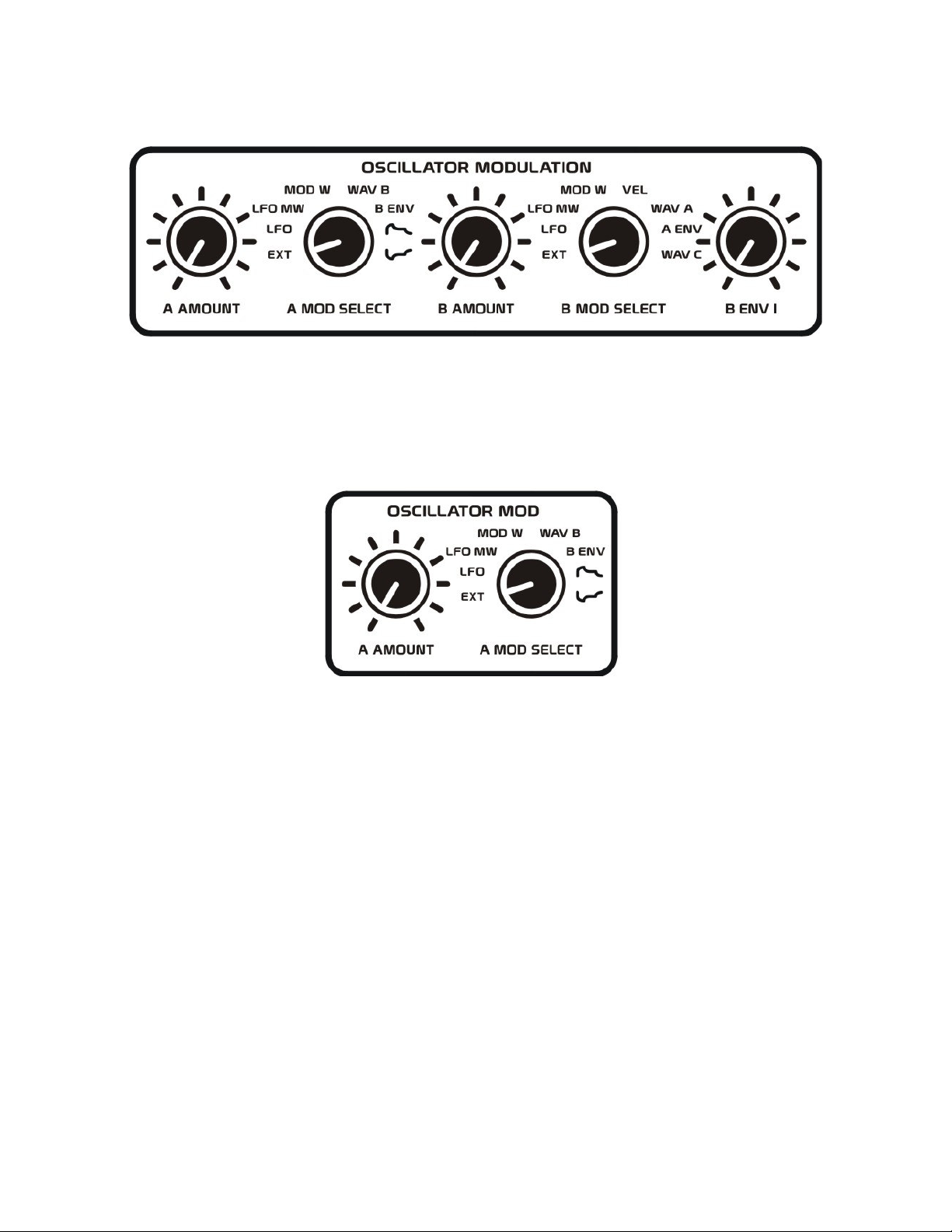
The A AMOUNT and A MOD SELECT controls are used to modulate the frequency of Oscillator A.
The A AMOUNT control sets the amount of modulation that the A MOD SELECT source will have on
Oscillator A’s frequency. When this control is rotated fully counter-clockwise, no modulation will
occur. As you rotate this control clockwise, the amount of modulation will increase.
The A MOD SELECT control selects which modulation source will be used to alter the frequency of
Oscillator A.
In the EXT position, any external control voltage connected to the OSC MOD input jack can be used to
modulate the frequency of Oscillator A. Keep in mind that positive control voltage will increase the
oscillator’s frequency, while negative control voltages will decrease the oscillator’s frequency.
The LFO setting will route the internal LFO to modulate Oscillator A. This LFO waveform will range
from –5 to +5 volts, causing Oscillator A’s frequency to rise about and fall below the normal frequency
for a note. You can use this to create vibrato-like effects.
The LFO MW setting lets the mod wheel messages from a MIDI keyboard control the amplitude of LFO
signal used to modulate Oscillator A’s frequency. In this way, one could record mod wheel messages
into a MIDI sequencer to animate the effect the LFO will have on Oscillator A’s frequency.
Page 25
23
ANALOG CONTROLS
The MOD W setting will route the Mod Wheel messages from a MIDI keyboard to modulate Oscillator
A’s frequency. With your mod wheel set to 0, there will be no affect on Oscillator A’s pitch. Increasing
the value of your mod wheel will cause Oscillator A’s frequency to increase accordingly.
The WAV B setting routes Oscillator B’s waveform, as determined by the WAVE B control setting, to
modulate the frequency of Oscillator A. Use this to create direct FM sounds when Oscillator B is in its
audio range, or more traditional vibrato effects when Oscillator B is producing frequencies below the
audio range. Note that all of Oscillator B’s waveforms range from –5 to +5 volts, causing Oscillator A’s
frequency to rise above and fall below the normal frequency for a note’s pitch.
The B ENV setting lets Envelope 1 control the amplitude of Oscillator B’s waveform, as determined by
the WAVE B control setting, to modulate Oscillator A’s frequency. This provides a more traditional
form of FM where the modulation source varies its amplitude over time.
The + ENVELOPE setting selects the positive polarity of Envelope 1 to sweep the frequency of
Oscillator A. Since envelope 1 has a range of 0 to +10 volts, this will cause Oscillator A’s frequency to
rise above the normal frequency for a note’s pitch.
The - ENVELOPE setting selects an inverted polarity of Envelope 1 to sweep the frequency of Oscillator A. Although Envelope 1 is now inverted it is also level-shifted keeping it in the 0 to +10 volts range
just as the positive polarity envelope. This will cause Oscillator A’s frequency to rise above the normal
frequency for a note’s pitch.
NOTE: Most traditional synthesizers with a negative polarity envelope would have a range of say
0 to –10 volts. The problem with this is if Oscillator A is our main audio source covering the entire
audio range, if we begin applying negative voltages to the frequency of an oscillator, the pitch can
be easily pushed below the audio range making it useless as an audio source. Instead the XS keeps its
inverted envelope in the same voltage range as the positive polarity envelope to keep this oscillator
within the usable audio range.
Page 26
24
ANALOG CONTROLS
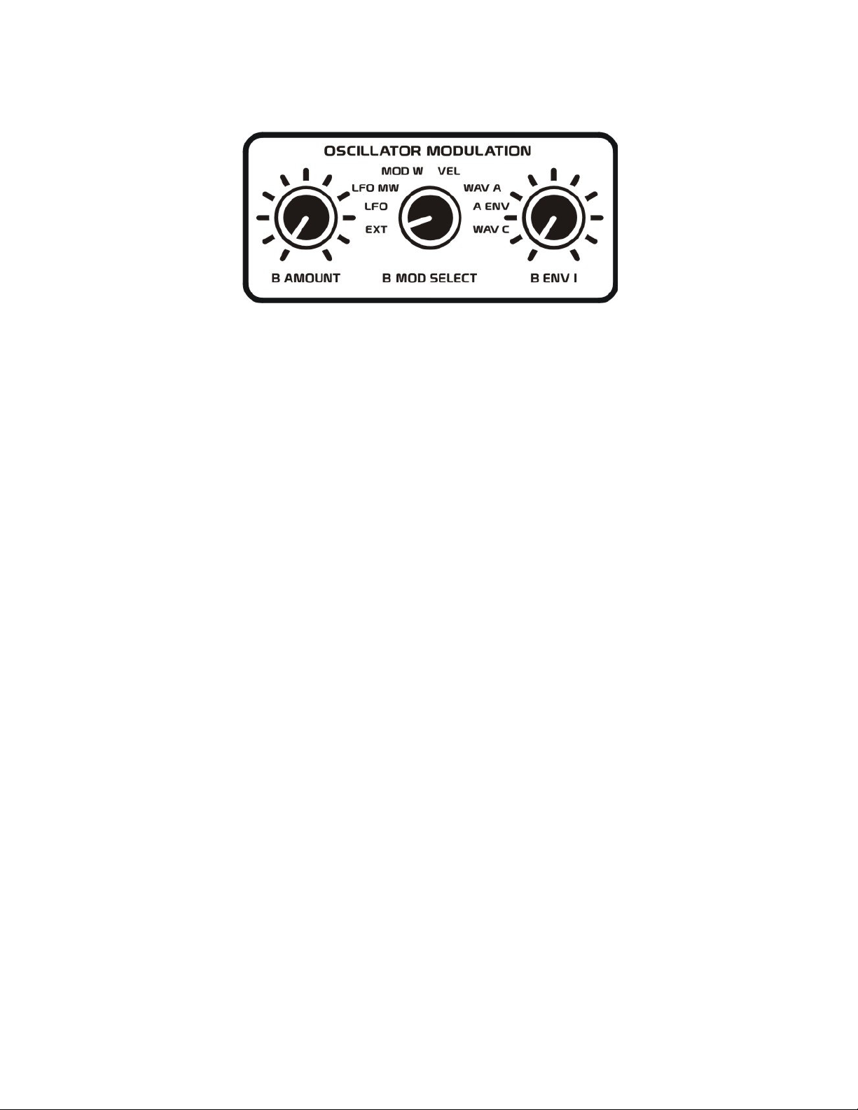
OSCILLATOR B MODULATION
The B AMOUNT, B MOD SELECT, and B ENV 1 controls are used to modulate the frequency of
Oscillator B.
The B AMOUNT control sets the amount of modulation that the B MOD SELECT source will have on
Oscillator B’s frequency. When this control is rotated fully counter-clockwise, no modulation will
occur. As you rotate this control clockwise, the amount of modulation will increase.
The B MOD SELECT control selects which modulation source will be used to alter the frequency of
Oscillator B.
In the EXT position, any external control voltage connected to the OSC MOD input jack can be used to
modulate the frequency of Oscillator B. Keep in mind that positive control voltage will increase the
oscillator’s frequency, while negative control voltages will decrease the oscillator’s frequency.
The LFO setting will route the internal LFO to modulate Oscillator B. This LFO waveform will range
from –5 to +5 volts, causing Oscillator B’s frequency to rise above and fall below the normal frequency
for a note’s pitch. You can use this to create vibrato-like effects.
The LFO MW setting lets the Mod Wheel messages from a MIDI keyboard control the amplitude of
LFO signal used to modulate Oscillator B’s frequency. In this way, one could record Mod Wheel
messages into a MIDI sequencer to animate the effect the LFO will have on Oscillator B’s frequency.
The MOD W setting will route the Mod Wheel messages from a MIDI keyboard to modulate Oscillator
B’s frequency. With your mod wheel set to 0, there will be no affect on Oscillator B’s pitch. Increasing
the value of your mod wheel will cause Oscillator B’s frequency to increase accordingly.
The VEL setting will route Velocity messages from a MIDI keyboard to modulate the frequency of
Oscillator B. The exception here is that if an external control voltage is inserted into the VEL IN jack,
this external control voltage will override Velocity messages received from the MIDI keyboard.
The WAV A setting routes Oscillator A’s waveform, as determined by the WAVE A control setting, to
modulate the frequency of Oscillator B. Use this to create direct FM sounds. Note that all of Oscillator
A’s waveforms, including white noise range from –5 to +5 volts, causing Oscillator B’s frequency to
rise above and fall below the normal frequency for a note’s pitch.
Page 27
25
ANALOG CONTROLS
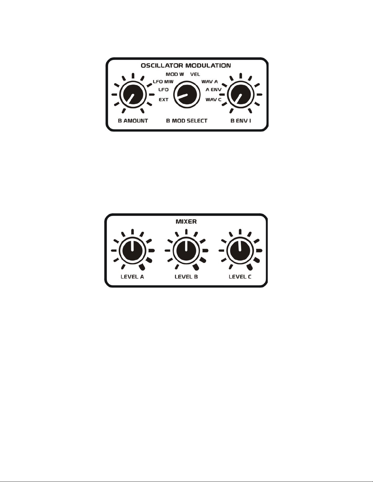
The A ENV setting lets Envelope 1 control the amplitude of Oscillator A’s waveform, as determined by
the WAVE A control setting, to modulate Oscillator B’s frequency. This provides a more traditional
form of FM where the modulation source varies its amplitude over time.
The B ENV 1 control sets the amount of pitch sweep that Envelope 1 will have on Oscillator B’s
frequency. When this control is rotated fully counter-clockwise, no pitch sweep will occur. As you rotate
this control clockwise, the amount of pitch sweep will increase. Since Envelope 1 has a range of
0 to +10 volts, this will cause Oscillator B’s frequency to rise above the normal frequency for a note’s
pitch.
MIXER
The XS provides a three-channel audio mixer for combining different audio sources that will be routed
to the input of the filter section. In addition to summing these audio signals going to the filter, the mixer
also allows you to overdrive the input of the filter section. Notice how the tick marks around the mixer
controls become increasingly thicker in appearance. This is to indicate where overdriving the filter input
will occur. If you are using a single audio source routed to the filter, you will typically want to set the
mixer level somewhere between the middle tick mark to two ticks to the right of the middle position to
provide the best signal-to-noise ratio and to maintain full resonance response in the filter. As you add
more audio sources to the mix you may need to decrease each part’s level to maintain full resonance
response in the filter. The harder you drive the input of the filter, the less noticeable effect filter
resonance will have.
LEVEL A: This control determines the amount of signal selected by the WAVE A control to be sent to
the filter.
LEVEL B: This control determines the amount of signal selected by the WAVE B control to be sent to
the filter.
LEVEL C: This control determines the amount of signal selected by the WAVE C control to be sent to
the filter.
Page 28
26
ANALOG CONTROLS
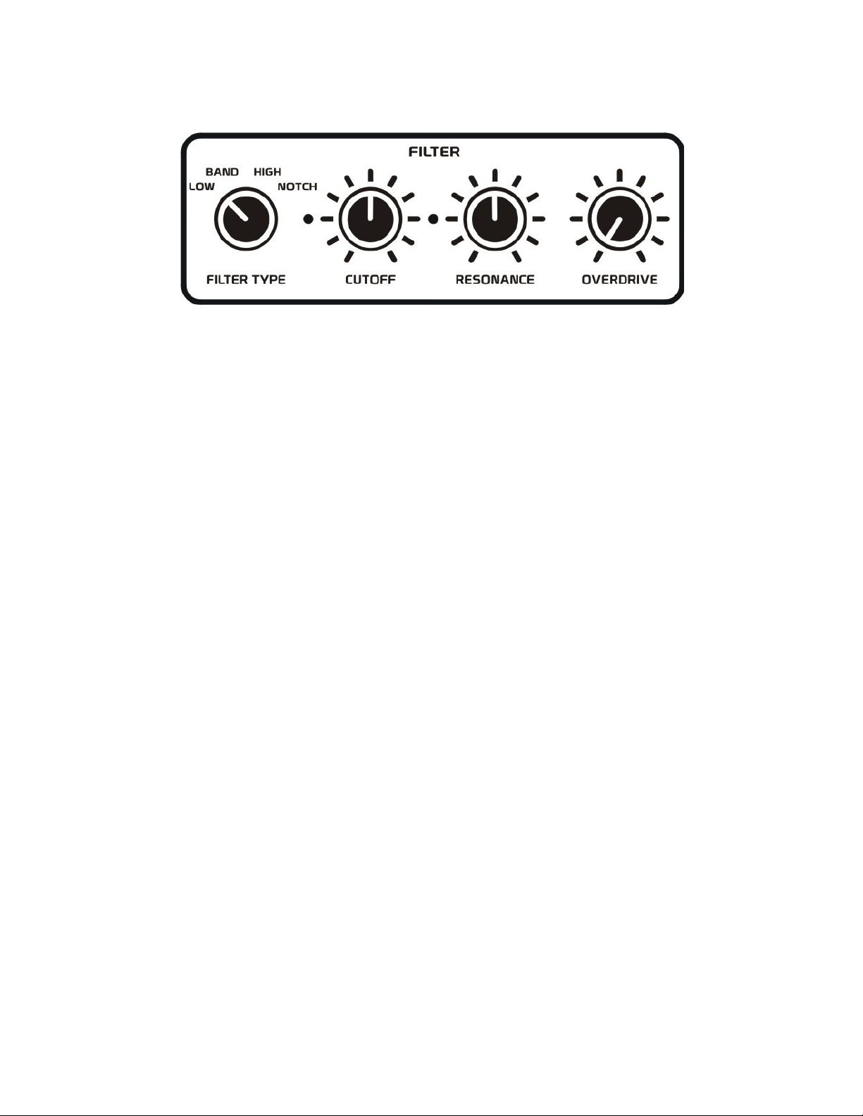
FILTER
The most common way to alter the harmonic content of a sound is by using a filter. The XS provides a
12 dB filter with four filter types including lowpass, highpass, bandpass, and notch responses. There is
also a cutoff control for determining the frequency of the filter and a resonance control for accentuating
these frequencies. In addition, the filter has a dedicated overdrive section at its output for adding that
essential extra crunch we love so much!
FILTER TYPE: The filter type control selects one of four possible filter responses to determine how the
filter will attenuate certain frequencies of a sound.
The LOW setting selects the lowpass filter, where low frequencies are allowed to pass through the filter
while higher frequencies are attenuated.
The BAND setting selects the bandpass filter, where only the frequencies closest to the filter’s cutoff
frequency are allowed to pass through the filter, while attenuating all frequencies higher and lower than
the cutoff frequency.
The HIGH setting selects the highpass filter, where only the high frequencies are allowed to pass
through the filter while the lower frequencies are attenuated.
The NOTCH setting selects the notch filter, where harmonics closest to the cutoff frequency are
attenuated while all other harmonics are allowed to pass through the filter.
CUTOFF: The cutoff control determines the point at which frequencies are attenuated by the filter.
The filter cutoff range is approximately 5 Hz to 18 kHz. Rotate this control counter-clockwise to select
lower frequency settings, or clockwise to select higher frequency settings for the filter. In addition to this
control, you can also use modulation sources to animate the filter’s cutoff frequency, which will be
described in more detail under the Filter Modulation section of the manual.
RESONANCE: The resonance control is used to increase or accentuate those frequencies closest to the
cutoff frequency set for the filter. When this control is rotated fully counter-clockwise, no resonance will
occur in the filter. By rotating this control clockwise more resonance will be introduced into the filter,
with the highest setting causing the filter to self-oscillate. When the filter self-oscillates it will produce a
pure sine wave tone that can be used as an audio source.
OVERDRIVE: The overdrive control clips the output of the filter in a unique way to provide harmonically rich tones. When this control is rotated fully counter clockwise, sounds will pass cleanly through
the filter without any distortion. Rotate this control clockwise to increase the amount of distortion.
Note the amount of signal being sent to the filter’s input will also affect the overdrive tone produced.
Page 29
27
ANALOG CONTROLS
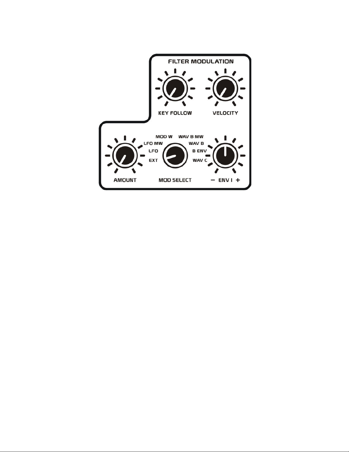
FILTER MODULATION
The filter modulation section of the XS provides a way to animate the cutoff frequency of the filter.
KEY FOLLOW: The key follow control allows the filter cutoff frequency to track the pitch of notes
received from a MIDI keyboard, when this control is rotated fully clockwise. With this control rotated
fully counter clockwise, no key tracking will occur.
TIP: The key follow control can also be useful when the filter is set to self-oscillate, producing a sine
wave, so then you can play the frequency that the filter is generating. Although the pitch tracking of the
filter is not nearly as precise as your typical oscillator, for the most part, it will track decently over a
three octave range.
VELOCITY: The velocity control will determine the amount of effect that Velocity messages from a
MIDI keyboard will have when attenuating the amplitude of Envelope 1 routed to sweep the filter’s
cutoff frequency. The exception here is that if an external control voltage is inserted into the VEL IN
jack, this external control voltage will override Velocity messages received from the MIDI keyboard.
When this control is rotated fully counter-clockwise, Velocity will have no effect on Envelope 1’s
overall amplitude. When this control is rotated clockwise, the amount of effect that Velocity has on
Envelope 1’s amplitude will increase. Therefore, higher Velocity values will generate larger envelope
sweeps, while lower Velocity settings will generate smaller envelope sweeps.
TIP: Using external Velocity control signals that swing both positive and negative can have interesting
results. For instance, if the Velocity input goes negative and is controlling Envelope 1’s amplitude, it
will cause the output of this envelope to become inverted. However, negative control voltages applied to
Envelope 2 (the amplifier) will not allow the amplifier to pass audio to the output during the negative
period. If you do not desire this effect on the amplifier, simply turn down the Velocity control for the
amplifier.
Page 30
28
ANALOG CONTROLS
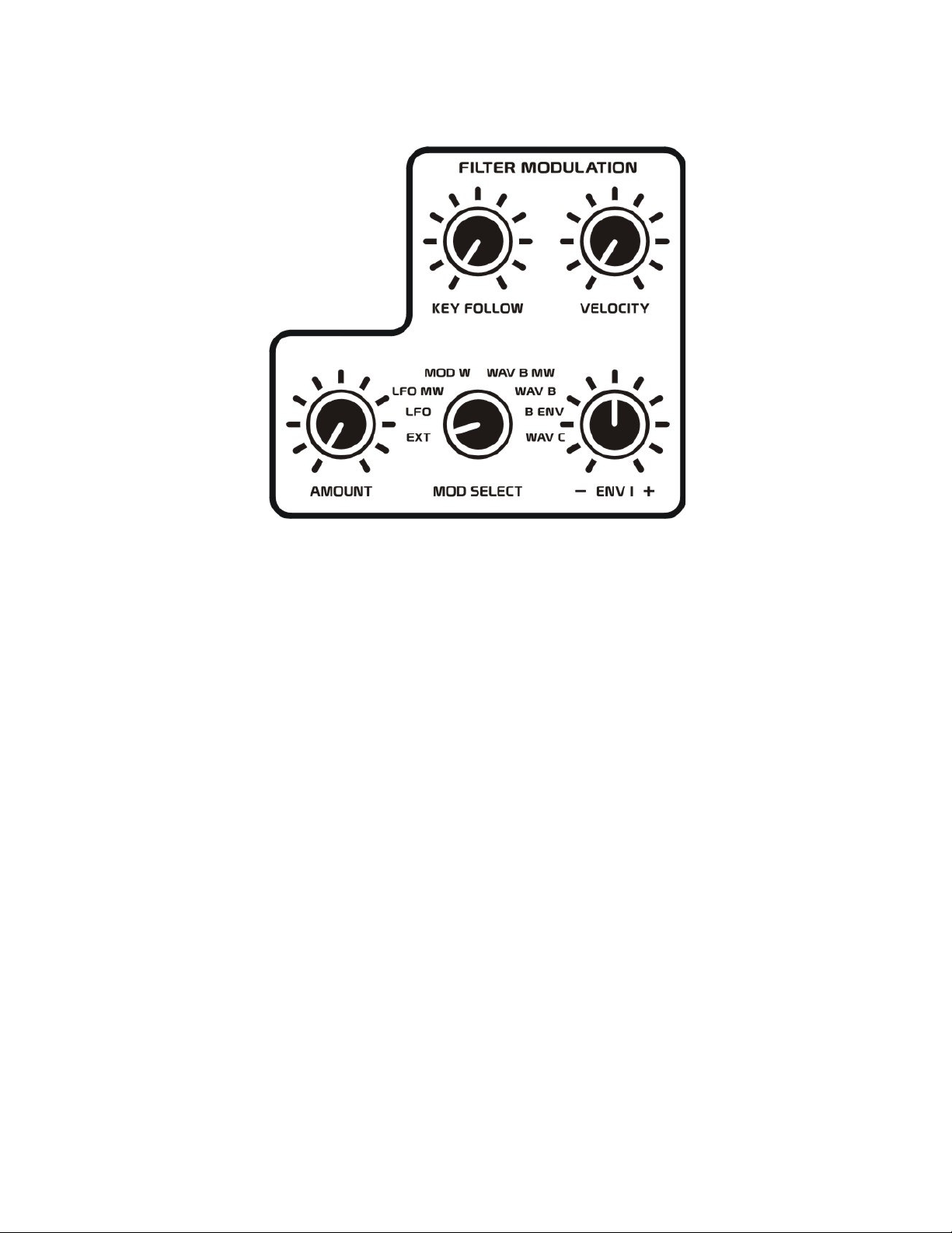
AMOUNT: The amount control sets the amount of modulation that the MOD SELECT source will have
on the filter’s cutoff frequency. When this control is rotated fully counter-clockwise, no
modulation will occur. As you rotate this control clockwise, the amount of modulation will increase.
MOD SELECT: The mod select control selects which modulation source will be used to alter the cutoff
frequency of the filter.
In the EXT position, any external control voltage connected to the FILTER MOD input jack can be used
to modulate the cutoff frequency of the filter. Keep in mind that positive control voltage will increase
the filter’s frequency, while negative control voltages will decrease the filter’s frequency.
The LFO setting will route the internal LFO to modulate the filter’s cutoff frequency. This LFO
waveform will range from –5 to +5 volts, causing the filter’s frequency to rise above and fall below the
normal frequency for the filter set by the cutoff control. You can use this to create slow or fast sweeping
type effects.
The LFO MW setting lets the Mod Wheel messages from a MIDI keyboard control the amplitude of
LFO signal used to modulate the filter’s cutoff frequency. In this way, one could record Mod Wheel
messages into a MIDI sequencer to animate the effect that the LFO will have on the filter’s frequency.
The MOD W setting will route the Mod Wheel messages from a MIDI keyboard to modulate the filter’s
cutoff frequency. With your mod wheel set to 0, there will be no affect on the filter’s frequency.
Increasing the value of your mod wheel will cause the filter’s frequency to increase accordingly.
The WAVE B MW setting lets the mod wheel messages from a MIDI keyboard control the amplitude of
WAVE B’s signal which is used to modulate the filter’s cutoff frequency. In this way, one could record
Mod Wheel messages into a MIDI sequencer to animate the effect that WAVE B’s waveform will have
on the filter’s frequency.
Page 31
29
ANALOG CONTROLS
The WAV B setting routes Oscillator B’s waveform, determined by the WAVE B control setting, to
modulate the filter’s cutoff frequency. Use this to create direct FM modulations when Oscillator B is in
its audio range, or to create slower sweeping effects when Oscillator B is producing frequencies below
the audio range. Note that all of Oscillator B’s waveforms range from –5 to +5 volts, causing the filter’s
frequency to rise above and fall below the filter frequency set by the filter’s cutoff control.
The B ENV setting lets Envelope 1 control the amplitude of Oscillator B’s waveform, determined by the
WAVE B control setting, to modulate the filter’s cutoff frequency. This provides a more complex form
of FM where the modulation source varies it’s amplitude over time.
The WAV C setting routes the waveform selected with the WAVE C control to modulate the filter’s
cutoff frequency. This allows you to modulate the filter’s cutoff frequency with any of the sub
oscillators, the ring modulator, the white noise source, or any external audio which is inserted into the
AUDIO IN jack.
Note that the ring modulator and the white noise source waveforms range from –5 to +5 volts, causing
the filter’s frequency to rise above and fall below the filter frequency set by the filter’s cutoff control,
while all three sub oscillator waveforms have a 0 to +15 volt range. When the sub oscillators are
selected for WAVE C and are modulating the filter’s cutoff frequency, the filter frequency will become
higher than that set with the filter’s cutoff control.
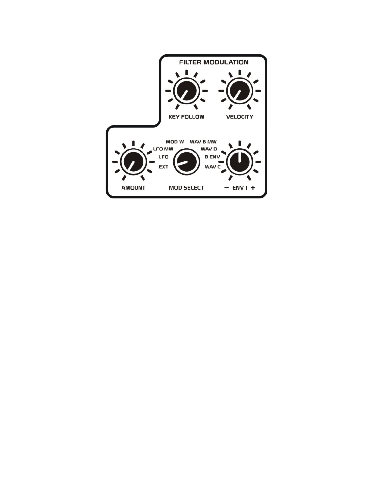
ENV 1 -/+: The ENV 1 control sets the amount of sweep that Envelope 1 will have on the filter’s cutoff
frequency. This control provides both positive and negative polarity envelope shapes to sweep the
filter’s frequency. With this control set to it middle position, Envelope 1 will have no effect on the
filter’s frequency. When this control is rotated counter-clockwise of the middle position negative
polarity envelope sweeps will occur. When this control is rotated clockwise of the middle position,
positive polarity envelope sweeps will occur. Since both positive and negative polarity envelope shapes
have a range of 0 to +10 volts, this will cause the filter’s frequency to always rise above the normal
frequency set with the filter’s cutoff control. This keeps both envelope polarities within the same usable
range to eliminate unnecessary adjustments of the filter’s cutoff frequency as is typical with most
synthesizers.
Page 32
30
ANALOG CONTROLS
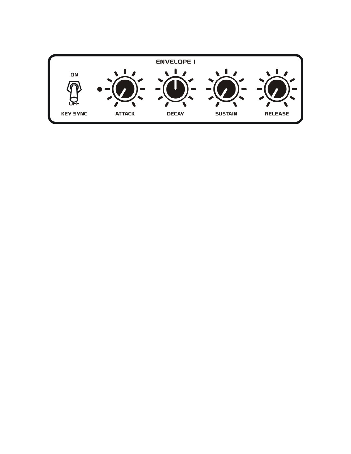
ENVELOPE 1
An envelope generator is designed to accurately and repetitively sweep sound parameters such as pitch,
tone or amplitude in a way which would be physically impossible for human hands to do.
Envelope 1 is the main modulation envelope in the XS. It can be used to modulate the frequency of the
internal oscillators and filter, as well as control external devices.
Envelope 1 is similar to a typical ADSR type envelope, with the addition of our unique accent envelope
times which will be described in more detail in the ACCENT section of this manual. This envelope has a
range of 0 to +10 volts. The Envelope 1 LED will light to indicate every time a note is being played.
KEY SYNC: When this switch is set to the ON position, each time a new note is played on your MIDI
keyboard, the envelope will start regenerating the attack portion of its shape from 0 volts. The exception
to this is that if a logic gate signal is inserted into the GATE IN jack, this logic signal will override
Note On/Off messages coming from your MIDI keyboard, and instead will use this external gate signal
to trigger the envelopes in the XS. When this switch is set to the OFF position, the attack portion of the
envelope will start at whatever amplitude the envelope is currently at when a new note is played.
ATTACK: The attack control determines the rate at which the envelope will transition from its
current amplitude to +10 volts. This attack time can vary from 0.5 milliseconds to 4 seconds. When this
control is rotated fully counter-clockwise, the fastest attack time will occur. Rotate this control
clockwise to increase the attack time.
Ideally the attack portion of the envelope will begin at 0 volts, unless a note was recently played and the
envelope has not yet fully decayed to 0 volts.
DECAY: Once the attack portion of the envelope has reached +10 volts, the DECAY control determines
the rate at which the envelope will transition from this +10 volt level to the amplitude set by the sustain
control. This decay time can vary from 2 milliseconds to 10 seconds. When this control is rotated fully
counter-clockwise, the fastest decay time will occur. Rotate this control clockwise to increase the decay
time.
SUSTAIN: The sustain control determines the level that the envelope will decay to as long as a note is
currently being played. This level can range from 0 to +10 volts. Rotate this control fully counterclockwise for the minimum sustain level. As you rotate this control clockwise the sustain level will
increase.
RELEASE: The release control determines the rate at which the envelope will transition from the envelope’s current level to 0 volts when a note is released from playing. When this control is rotated fully
counter-clockwise the fastest release time will occur. Rotate this control clockwise to increase the release time.
Page 33
31
ANALOG CONTROLS
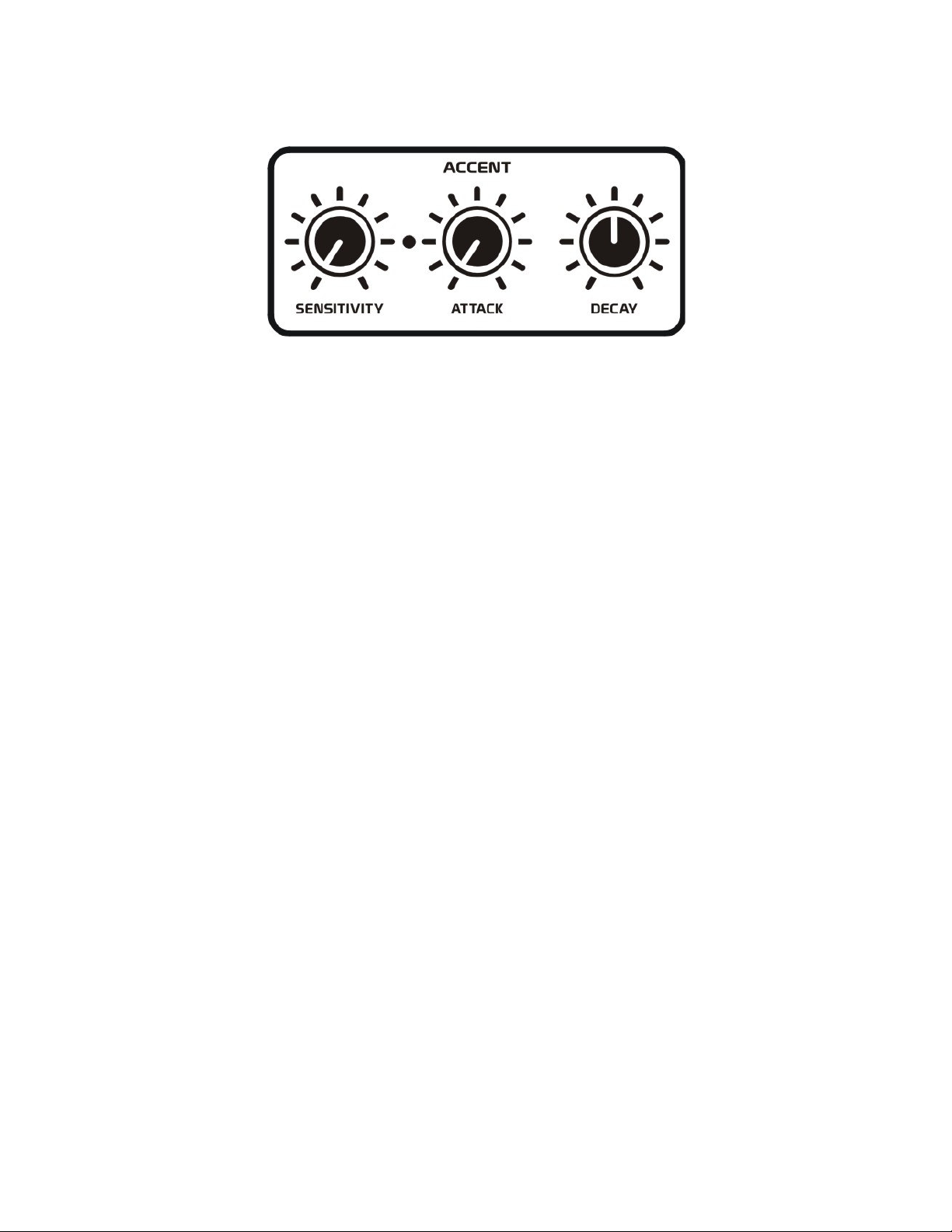
ACCENT
The accent section determines how Velocity messages received from a MIDI keyboard will affect the
envelopes in the XS. The exception here is that if an external control voltage is inserted into the VEL IN
jack, this external control voltage will override Velocity messages received from the MIDI keyboard,
allowing the external control voltages to trigger the accent circuit instead.
This accent section provides additional attack and decay times for Envelope 1, and a sensitivity control
that determines at what level will the Velocity make both Envelopes 1 and 2 use their accent times
instead of their normal times.
SENSITIVITY: The sensitivity control determines what level of Velocity will activate the accent
envelope times. When the sensitivity control is rotated fully counter-clockwise, no internal Velocity
value will be great enough to make the envelopes use their accent times. The exception here is that if an
external control voltage is inserted into the VEL IN jack, and this signal goes higher than +10 volts it
could still activate the accent envelope times. When the sensitivity control is rotated fully clockwise, all
internal Velocity values will cause the envelopes to use their accent times. The exception here is if an
external control voltage is inserted into the VEL IN jack, and this signal goes more negative than 0 volts
it could cause the envelopes to use their normal times instead.
Settings of the sensitivity control other than the extreme high or low values will cause the certain lower
Velocity values to trigger the normal envelope times while higher Velocity values will trigger the accent
envelope times.
When a Velocity value exceeds the sensitivity threshold, the accent LED indicator will light to show that
the accent decay times are currently being used for Envelopes 1 and 2.
ATTACK: The attack control determines the rate at which the envelope will transition from its current
amplitude to +10 volts when the accent section is activated by Velocity. This attack time can vary from
0.5 milliseconds to 4 seconds. When this control is rotated fully counter-clockwise, the fastest attack
time will occur. Rotate this control clockwise to increase the attack time.
Ideally, the attack portion of the envelope will begin at 0 volts, unless a note was recently played and the
envelope has not yet fully decayed to 0 volts.
DECAY: Once the attack portion of the envelope has reach +10 volts, the DECAY control determines
the rate at which the envelope will transition from this +10 volt level to the amplitude set by the sustain
control when the accent section is activated by Velocity. This decay time can vary from 2 milliseconds
to 10 seconds. When this control is rotated fully counter-clockwise the fastest decay time will occur.
Rotate this control clockwise to increase the decay time.
Page 34
32
ANALOG CONTROLS
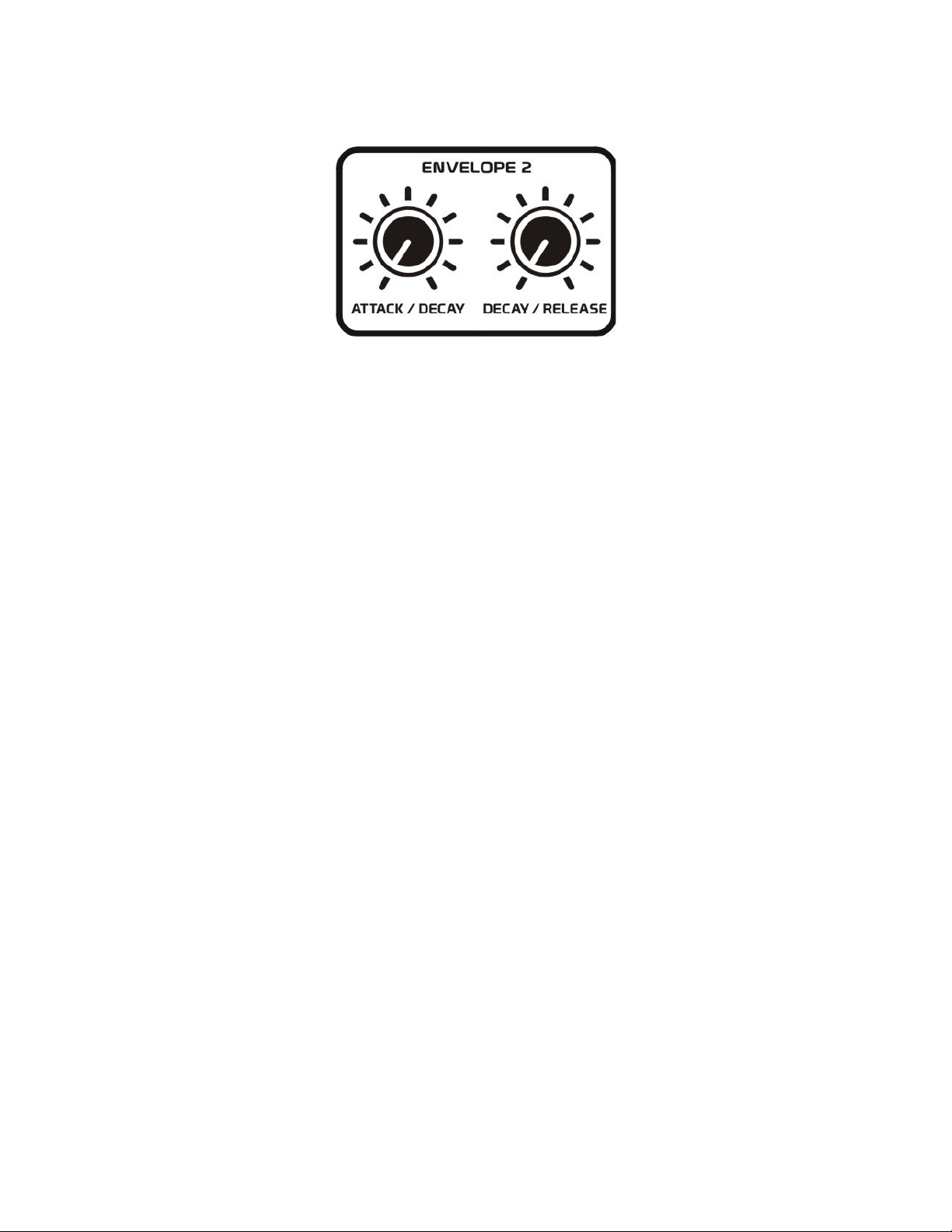
ENVELOPE 2
The XS provides four envelope types to help shape the amplitude of a sound passing through the
amplifier.
These envelope types include attack/decay, attack/sustain/release, accented decay/sustain/release, and
accented decay/normal decay. Only two controls, however, are required to set these various envelope
times.
ATTACK/DECAY: The attack/decay control determines the rate at which the envelope will transition
from its current amplitude to +10 volts, when the attack/decay or attack/sustain/release envelope types
are selected in the amplifier section. This attack time can vary from 1 milliseconds to 4 seconds.
If the accented decay/sustain/release or accented decay/normal decay envelope types are selected in the
amplifier section, this control will then determine the accented rate at which the envelope will decay to 0
volts. This decay time can vary from 3 milliseconds to 7 seconds.
When this control is rotated fully counter-clockwise, the fastest attack or decay time will occur
depending on the envelope type selected. Rotate this control clockwise to increase the attack or decay
time depending on the envelope type selected.
Ideally the attack portion of the envelope will begin at 0 volts, unless a note was recently played and the
envelope has not yet fully decayed to 0 volts.
DECAY/RELEASE: The decay/release control determines the rate as which the envelope will decay
from its current level to 0 volts, when the attack/decay or attack/sustain/release envelope types are
selected in the amplifier section. NOTE: the sustain level is always +10 volts; however, if the attack
portion of the envelope has not yet reached +10 volts, the envelope will start decaying from whatever
level the envelope is currently at.
If the accented decay/sustain/release or accented decay/normal decay envelope types are selected in the
amplifier section, this control will then determine the accented rate at which the envelope will decay
from +10 to 0 volts. This decay time can vary from 3 milliseconds to 7 seconds.
When this control is rotated fully counter-clockwise the fastest decay or release time will occur
depending on the envelope type selected. Rotate this control clockwise to increase the decay or release
time depending on the envelope type selected.
NOTE: The SENSITIVITY control in the ACCENT section determines when both Envelopes 1 and 2 will
use their accent envelope times. However only two envelope types for the amplifier use these accented
envelope times. These envelopes are the accented decay/sustain/release, and accented decay/normal
decay type envelopes.
Page 35
33
ANALOG CONTROLS
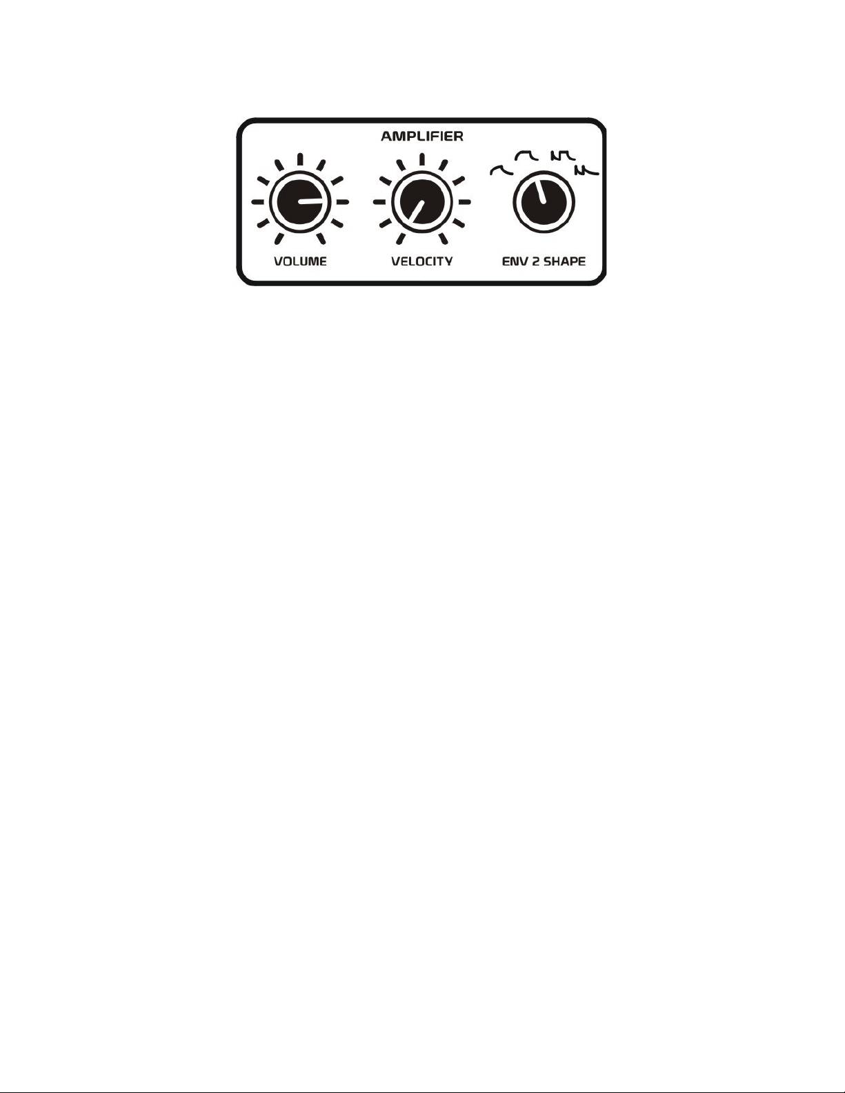
AMPLIFIER
The amplifier is used to shape the overall volume or amplitude of a sound.
The XS provides four envelope types to help shape the amplitude of sounds passing through the
amplifier.
These envelope types include attack/decay, attack/sustain/release, accented decay/sustain/release, and
accented decay/normal decay. The amplifier’s envelopes are also Velocity sensitive to add dynamic
expression to your playing.
VOLUME: The volume control determines the overall level of audio sent to the MAIN OUT jack.
Adjust this control for maximum output level to your mixer or audio system.
VELOCITY: The velocity control will determine the amount of effect Velocity messages from a MIDI
keyboard will have on the overall amplitude of Envelope 2 controlling the amplifier. The exception here
is that if an external control voltage is inserted into the VEL IN jack, this external control voltage will
override Velocity messages received from the MIDI keyboard.
When this control is rotated fully counter-clockwise, Velocity will have no effect on the Envelope 2’s
amplitude. When this control is rotated clockwise, the amount of effect Velocity has on Envelope 2’s
amplitude will increase. Therefore, higher Velocity values will generate slightly higher than normal
envelope levels, while lower Velocity settings will generate smaller envelope levels.
TIP: Using external Velocity control signals which swing both positive and negative can have interesting results. Negative Velocity control voltages applied to Envelope 2 (the amplifier) will not allow the
amplifier to pass audio to the output during the negative period of a control voltage. If you do not desire
this effect on the amplifier, simply turn down the Velocity control for the amplifier. On the other hand,
you could insert a modulation source such as the LFO OUT signal into the VEL IN jack and have the
amplifier create tremolo-like effects.
ENV 2 SHAPE: This control selects the shape of Envelope 2 which will affect the amplifier’s volume.
Select the ATTACK/DECAY setting to create sounds that require only an attack, a decay, or both
attack and decay. This type of envelope is nice for simple pads or even percussion sounds.
Select the ATTACK/SUSTAIN/RELEASE setting to create sounds which may require an attack or
release. This type of envelope is nice for many traditional sounds, including leads and basslines.
Select the ACCENTED DECAY/SUSTAIN/RELEASE setting to create Velocity controlled sounds that
are capable of imitating a pluck/strum effect, or an alternating percussive/lead-type sound.
Select the ACCENTED DECAY/NORMAL DECAY setting to create Velocity controlled percussive
sounds that require alternating decay times.
Page 36
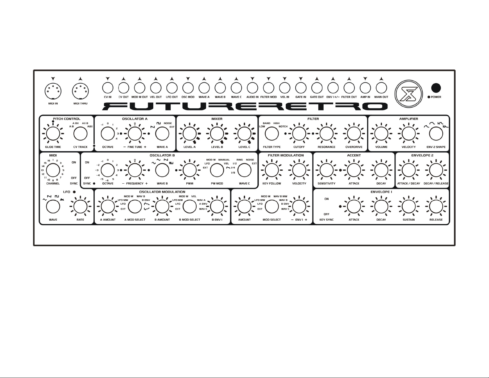
34
PATCH NAME: __________________________________
Page 37
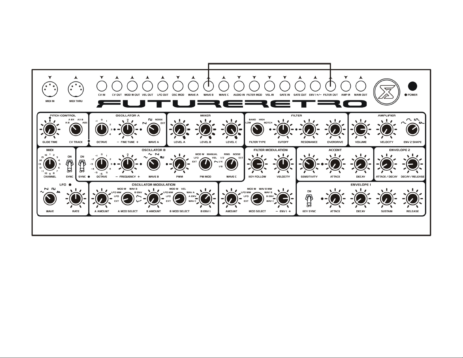
NOISE KICK
Nice sine wave kick with white noise attack. Connect the WAVE B jack to the FILTER OUT jack.
35
Page 38
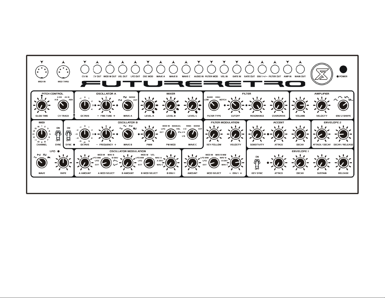
36
TECHNO KICK
Tight kick using just the filter self oscillating.
Page 39
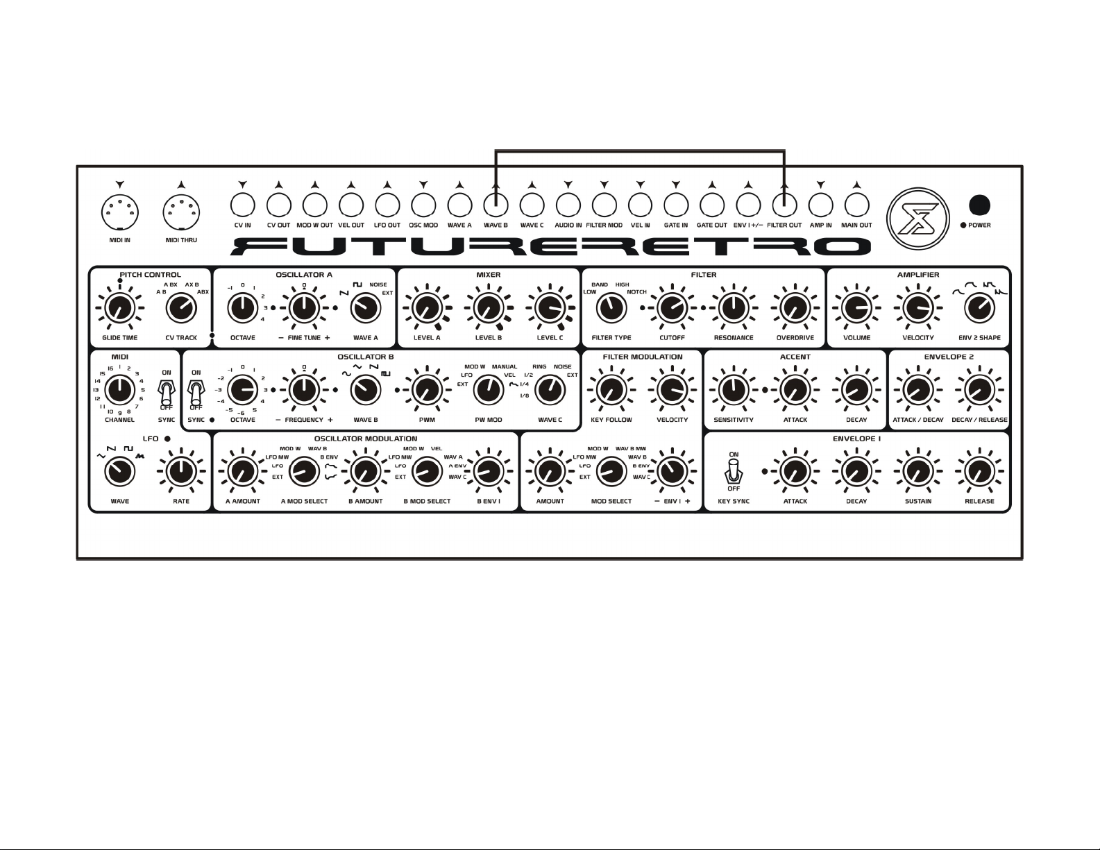
SNARE DRUM
Electronic snare drum, similar to the classics. Connect the WAVE B jack to the FILTER OUT jack. Notice how we take the output of WAVE B and insert it into the
FILTER OUT jack. By doing so we sum the output of the filter with WAVE B.
37
Page 40
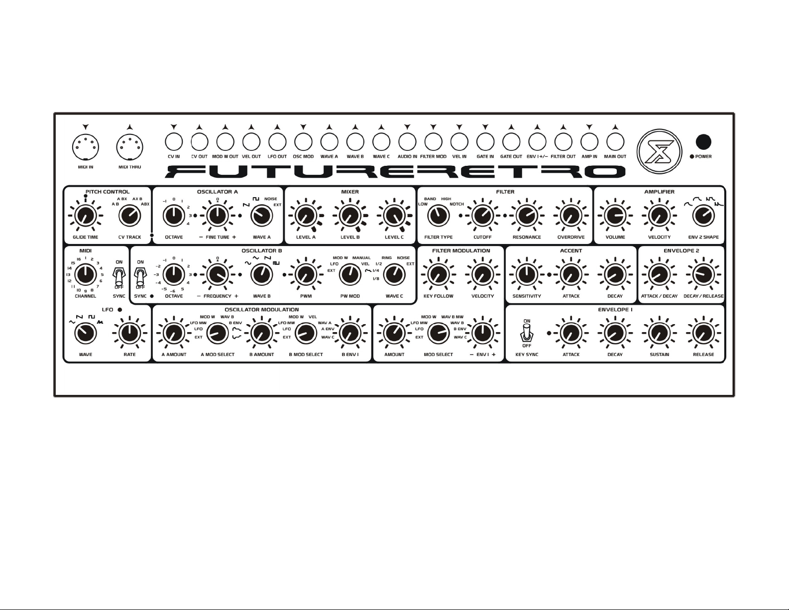
38
HAND CLAP
Electronic hand clap sound. Try varying the velocity of notes to change the duration of the clap.
Page 41
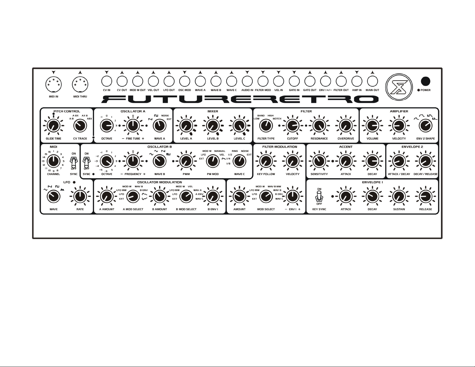
HIGH HATS
Electronic high hat sounds. Try playing with the filter cutoff frequency, Oscillator B’s frequency and modulation amount to dial in the tone. Adjust envelope 2’s attack
and decay controls to vary the open/closed high hat durations. Use varying velocity values to trigger open or closed high hat durations.
39
Page 42
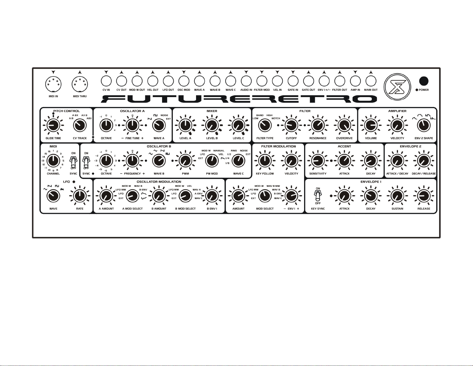
40
DISTORTED BASS / LEAD
Nice and crunchy, just the way we like! Record mod wheel movements in your sequencer to animate the filter cutoff frequency. And experiment with play notes with
different velocity values, and selecting different filter types.
Page 43
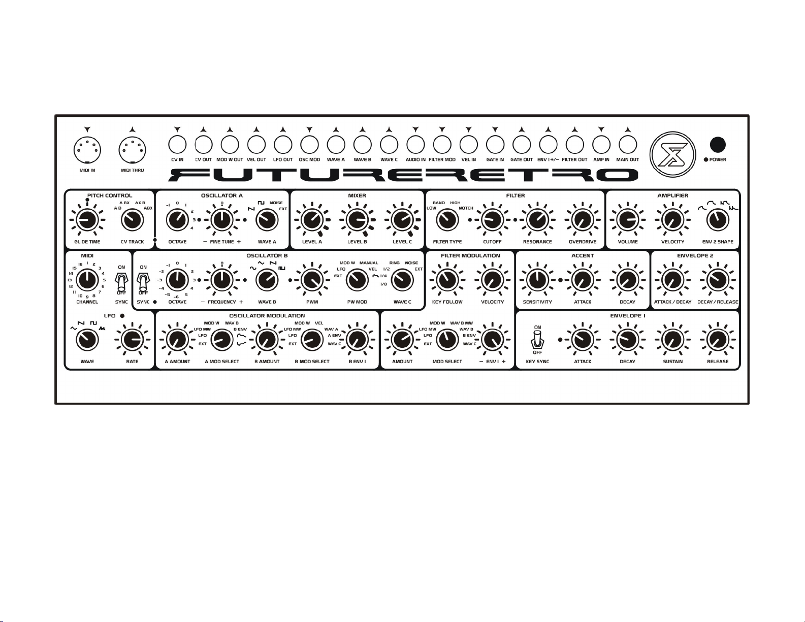
FUNKY TRANCE LEAD
Nice full lead sound. Play different velocity values to vary the attack portion of the sound. Adjust the mod wheel to change the filter frequency.
41
Page 44
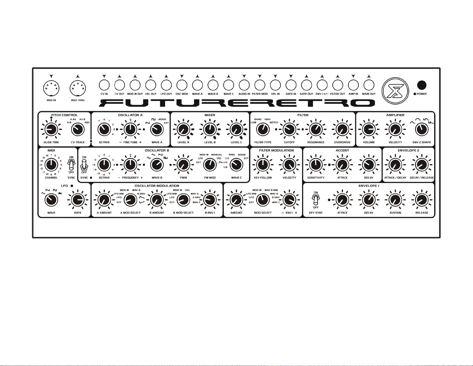
42
CLASSIC SYNC LEAD
Your typical synced lead sound. For a more aggressive sound, try increasing the overdrive amount. Play notes with varying velocity values to change the brightness of
the filter frequency.
Page 45
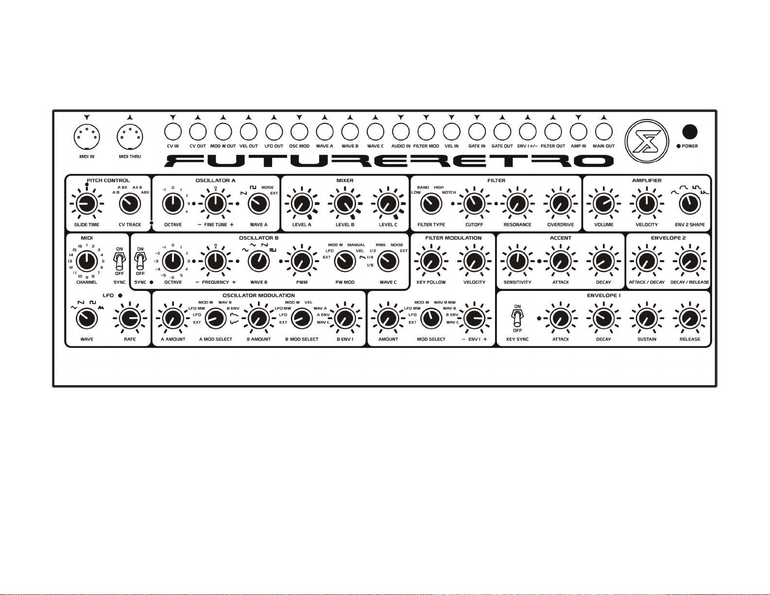
PHAT SAW
Nice in-your-face bass sound. For bass bin rockers, try selecting Octave –1 and the sine wave for Oscillator B.
43
Page 46
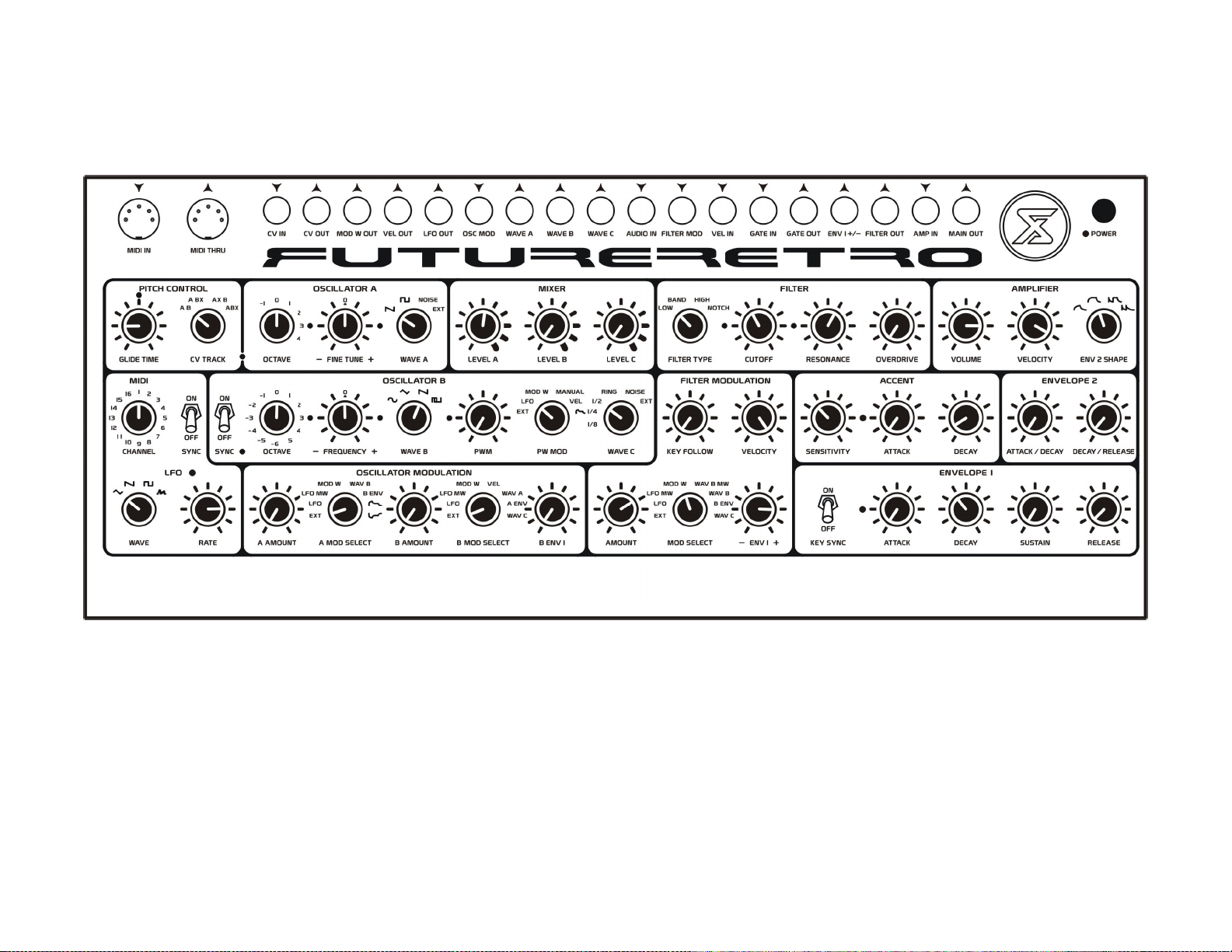
44
ACID BASS
Not quite a 303 but similar. Use Mod Wheel messages to control the filter cutoff frequency. Try using the different filter types, and increase the overdrive for a more
aggressive sound.
Page 47
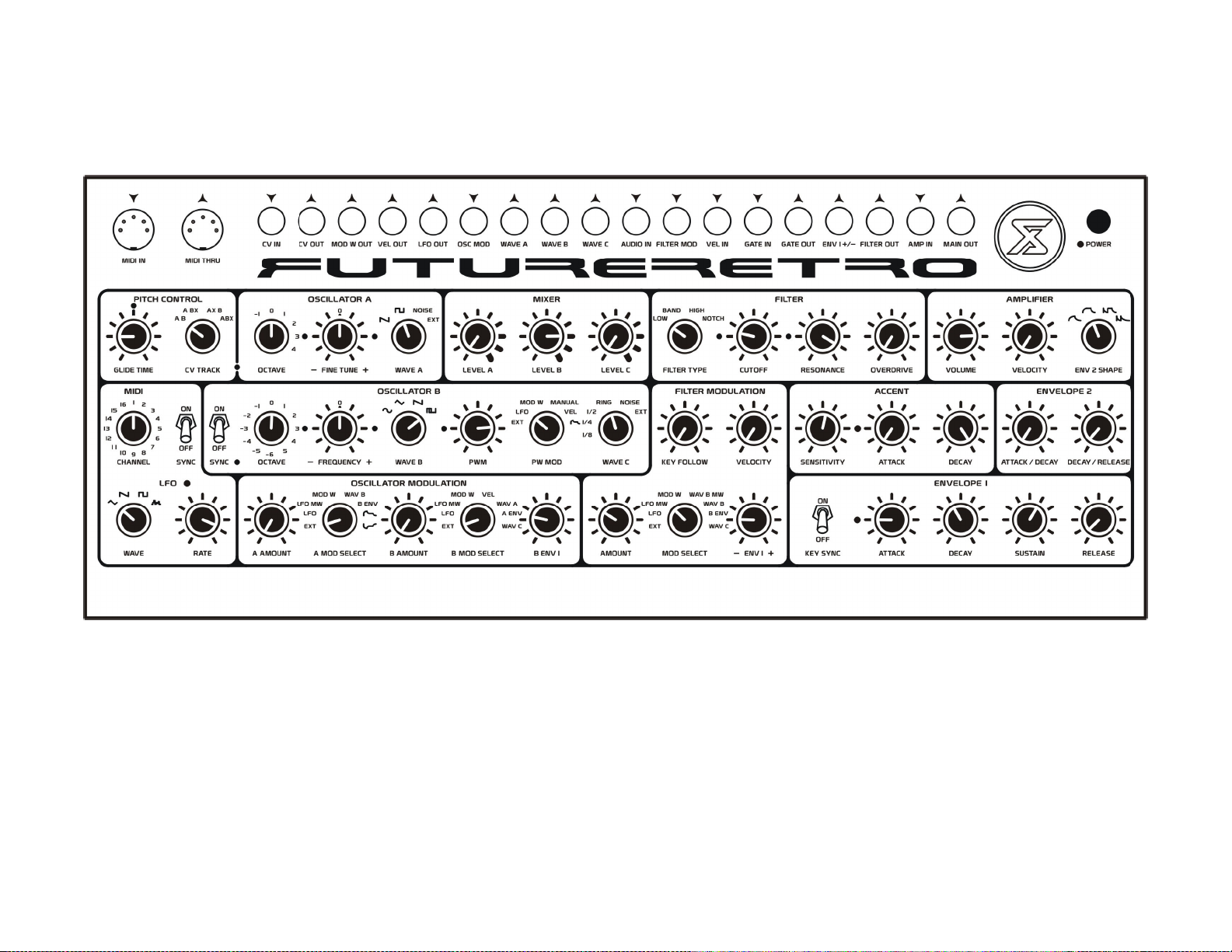
JUNGLE BASS
Nice warbling tones for your subs. Increase the mod wheel setting to increase the warble effect.
45
Page 48
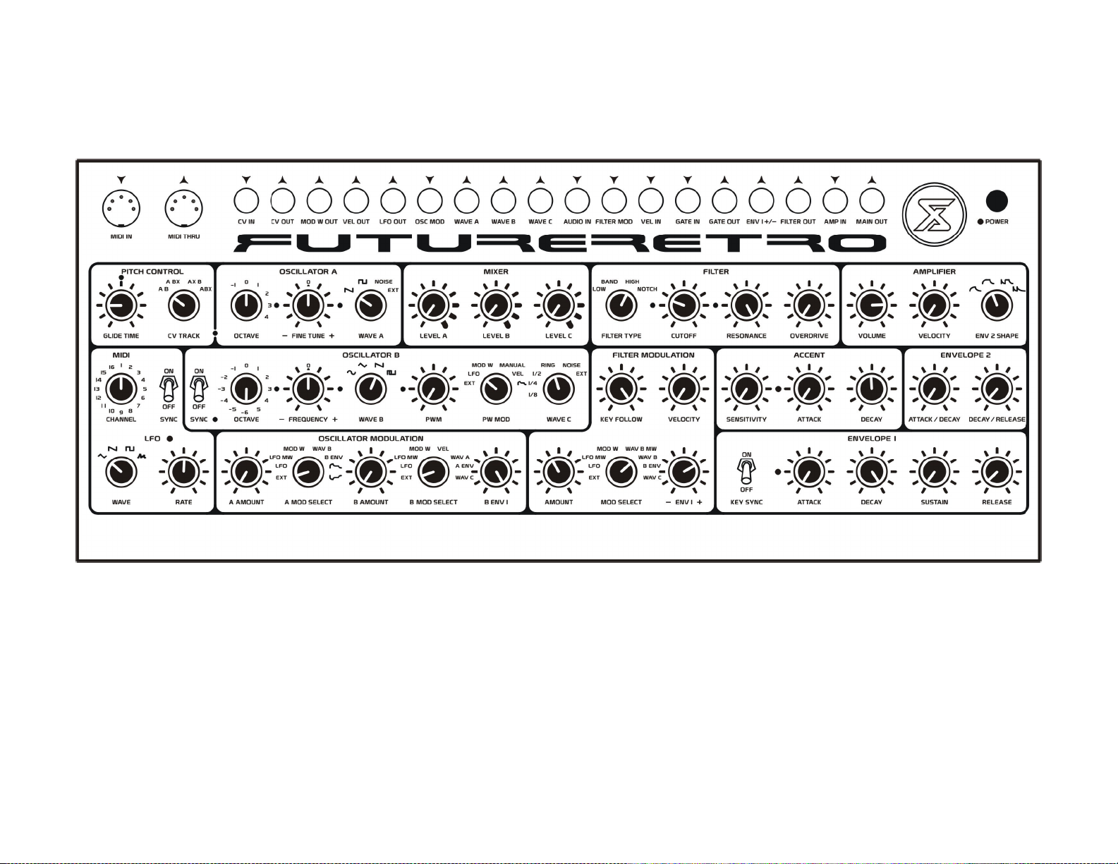
46
WINDING DOWN
More of a typical sci-fi transition effect. Experiment with various control settings to suit to your taste.
Page 49
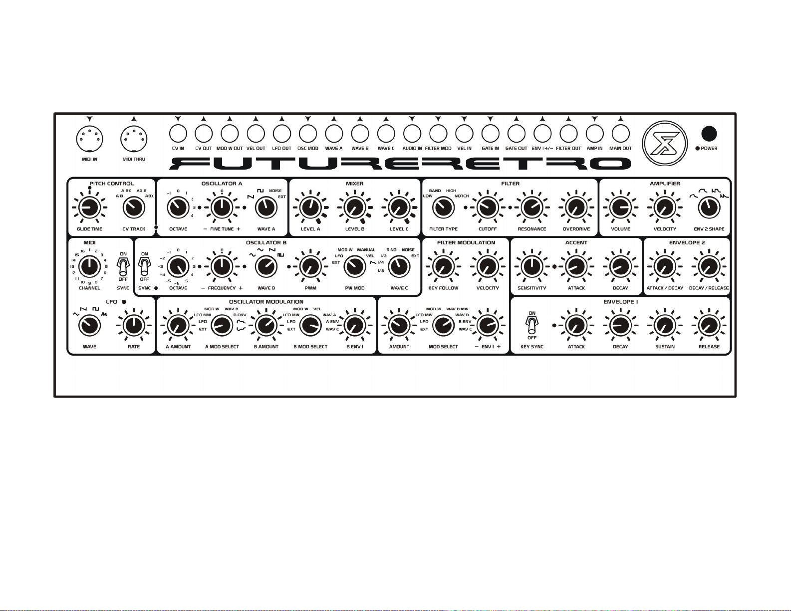
BUZZY BASS
Nice bass with some added high frequency content.
47
Page 50
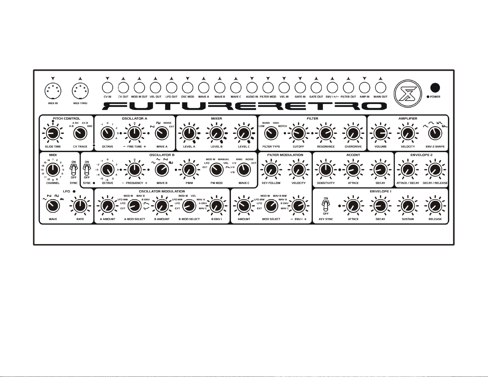
48
8 BIT TALKING BASS
Nice lo-fi bass sound. Try varying the velocity notes are played.
Page 51
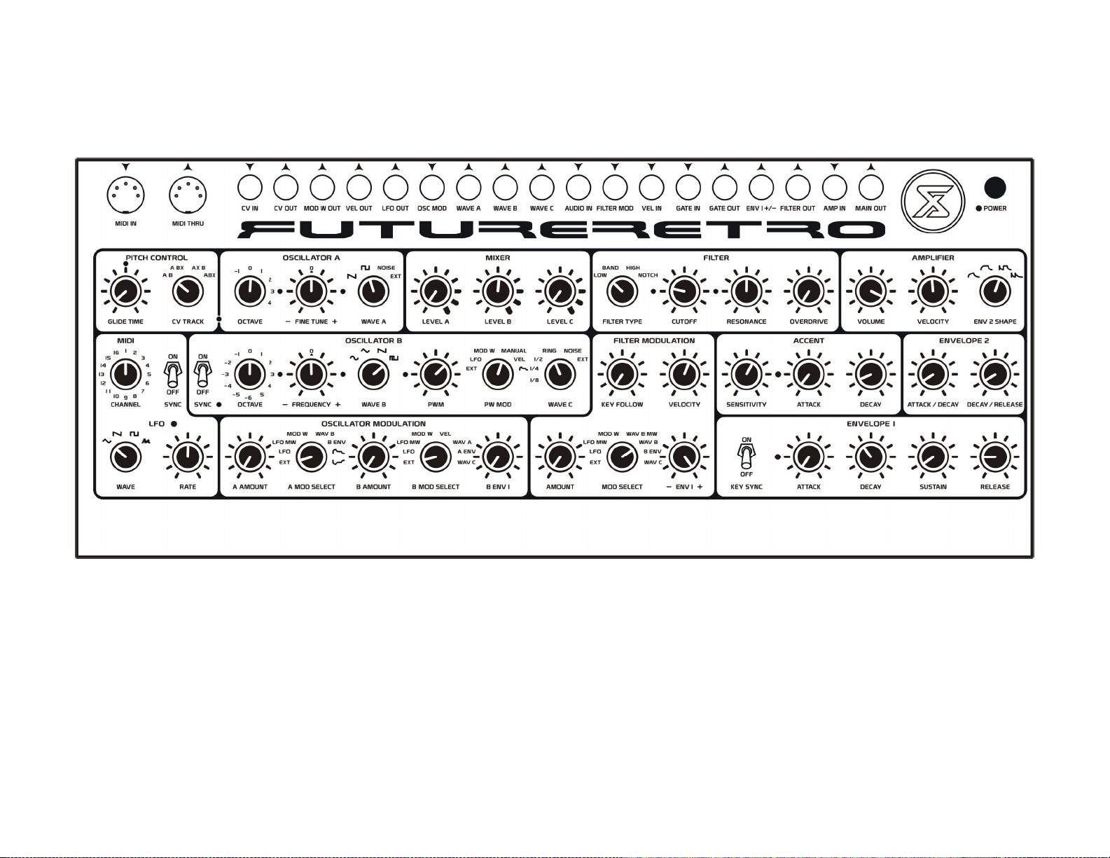
ELECTRIC BASS
More realistic bass sound. Try playing notes with different velocity values to achieve a pluck / strum effect.
49
Page 52
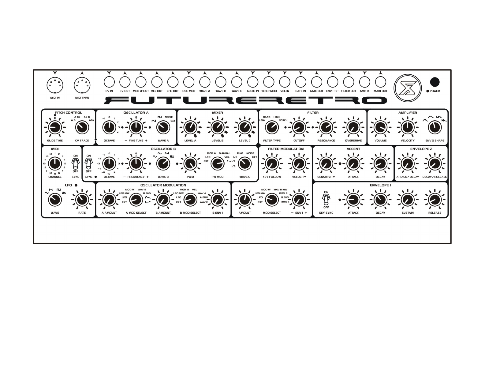
50
PHAT STACK PHASED
Thick lead sound. Here we use the notch filter to obtain a phased sound. Adjust the LFO rate to change the phasing rate.
Page 53
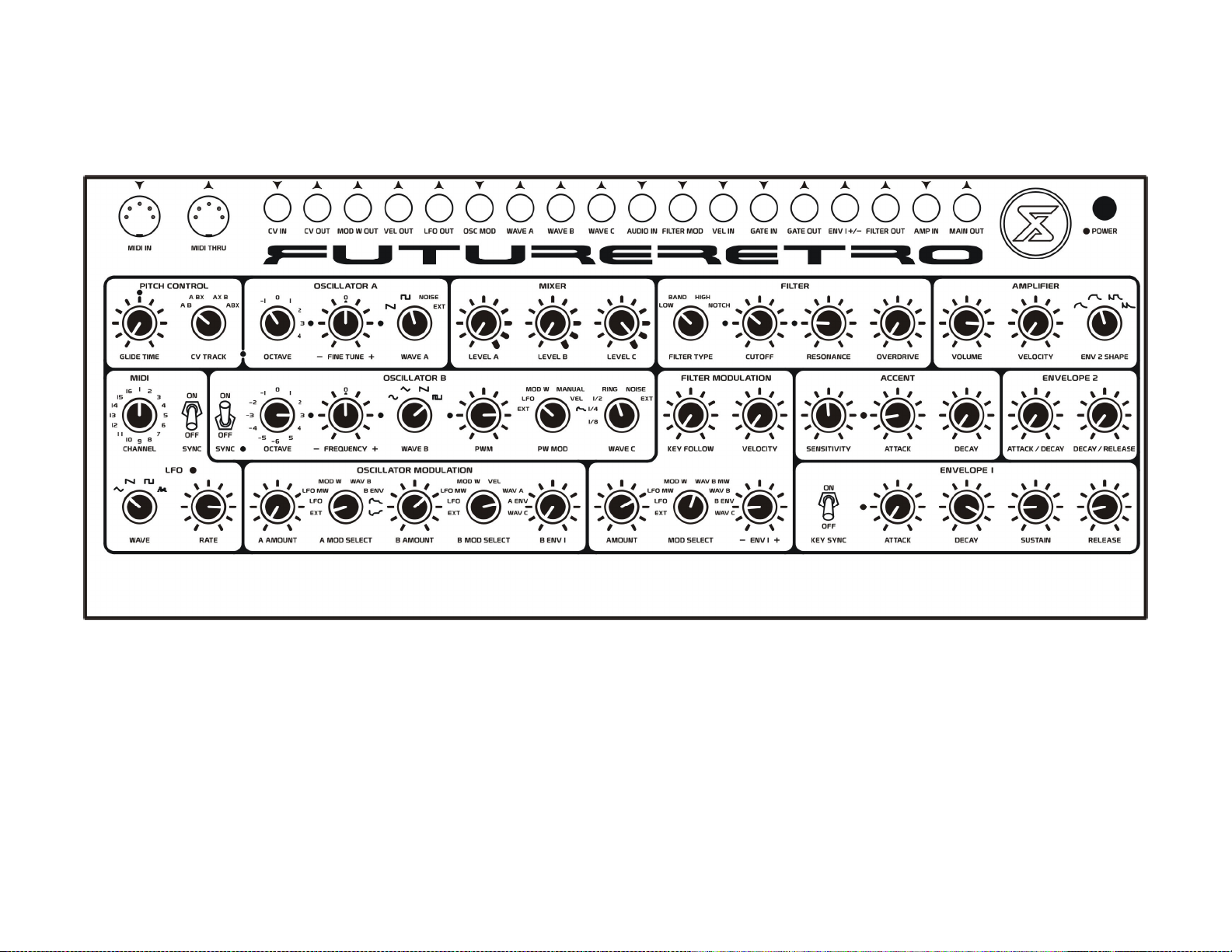
GRINDER
Metallic-like tones, nice for low end trance pads.
51
Page 54
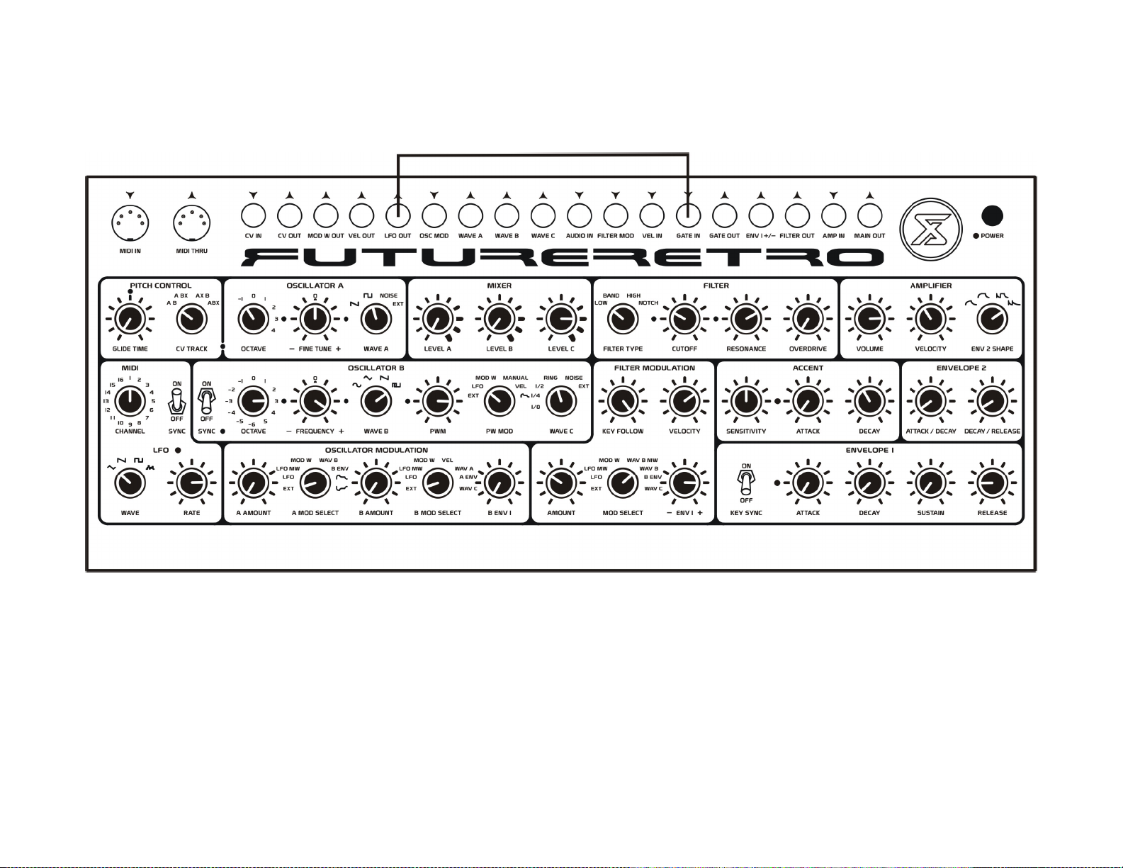
52
MIDI SYNCED PSEUDO ARPEGGIATOR
Play notes on your MIDI controller or sequencer to control the pitch. Try setting the LFO to different clock divisions. Connect the LFO OUT jack to the GATE IN jack.
If Envelope 1’s Key Sync control is set to ON, Envelope 1 can then be retriggered by both the LFO and any MIDI notes received by the XS. If the Key Sync control is
set to OFF, only the LFO will trigger Envelope 1.
Note, you can use the square wave output of the LFO to clock your other analog sequencers in a similar way. Just connect the LFO OUT jack to the CLOCK IN of your
sequencer or arpeggiator.
Page 55
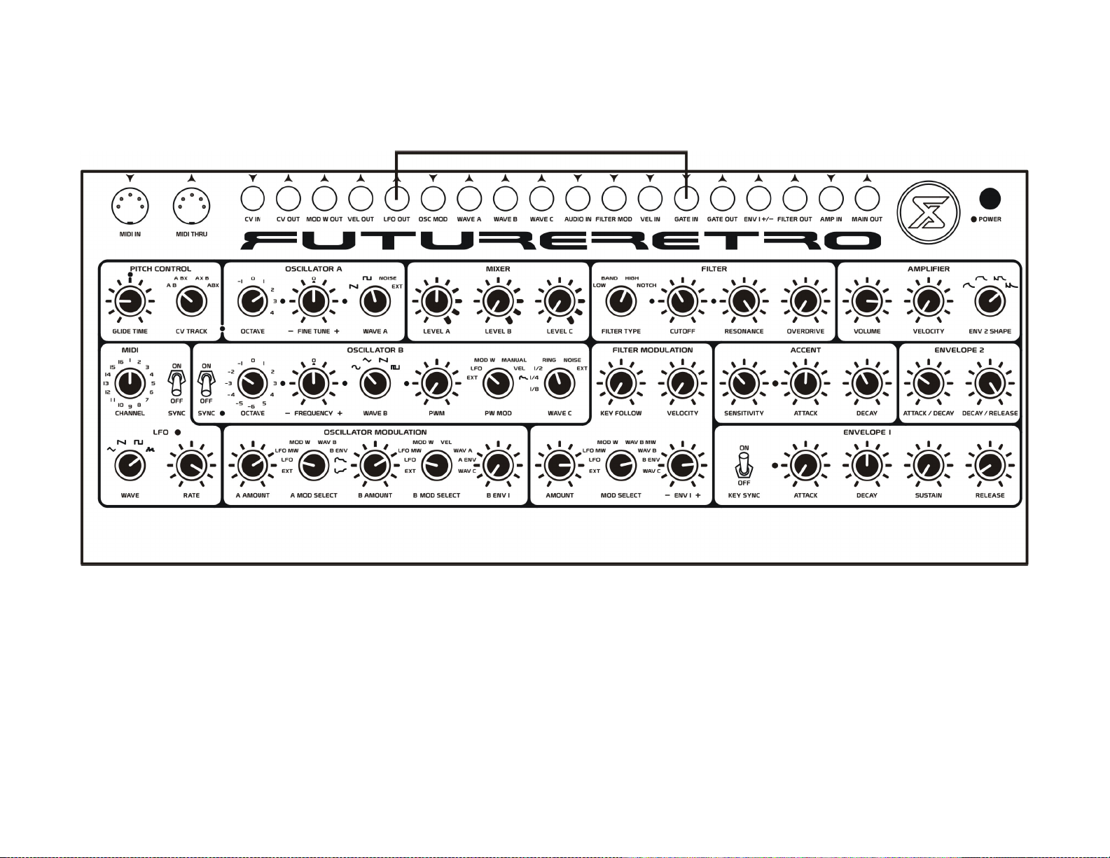
COMPUTER
This is more of a chaotic beep generator patch. Connect the LFO OUT jack to the GATE IN jack.
53
Page 56
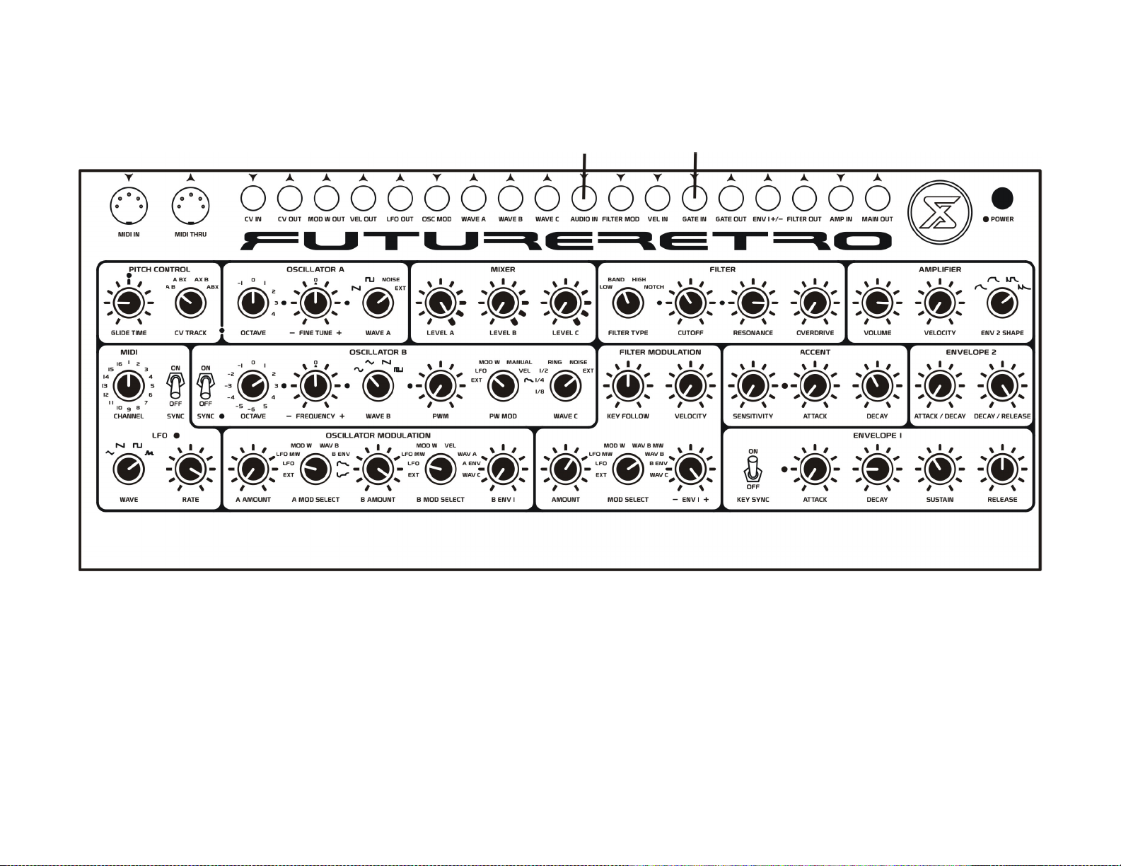
54
STRANGE BEATS
Here’s one way to mangle your beats. If your drum machine has stereo outputs, route one channel to the AUDIO IN jack, and the other to the GATE IN jack. In this way
the audio is also triggering the envelope generators. But you need to make sure the output of the drum machine is loud enough to trigger the envelopes in the XS. As an
alternative, you could connect the FILTER OUT jack directly to your mixer, or you could use MIDI notes to trigger the envelopes as well. But to do so you would first
need to remove the cable connected to the GATE IN jack. Adjust the filter cutoff frequency to suit your taste. And experiment with different Envelope 1 time settings.
Page 57

55
TIPS AND TRICKS
LATCH A NOTE
In some cases you may find it desirable to latch a Note On to create droning-type sounds without having
to constantly play a note on a MIDI keyboard or sequencer. To do so, play a note on your MIDI
keyboard and then change the MIDI Channel control to a different value, and then release the key of
your MIDI keyboard. What happens is the XS receives the proper MIDI Note On to play a sound, but
since we’ve changed the MIDI channel the XS responds to, it never receives the proper note off to stop
playing the sound. It is important to remember which MIDI note you have latched so that you can
unlatch it. To unlatch the note, play the same note on your MIDI keyboard and then change the MIDI
Channel control of the XS back to the value you are sending MIDI data on, and then release that note on
your MIDI keyboard. This then generates the proper MIDI Note Off command for the XS to stop
playing the latched note.
SPECIAL USES FOR THE OSCILLATOR OUTPUTS
As mentioned in the Connections section of this manual, both the WAVE A and WAVE B outputs
provide continuous signals on the tip portion of the jack, while the ring portion of the jack provides the
same signal attenuated by Envelope 1’s shape. Here are some neat things you can do with the
envelope-controlled signal:
You could take one of these envelope-controlled outputs (let’s say Oscillator B) and run it back into the
AUDIO IN jack. Use the WAVE C control to select External as its source to use the envelope-controlled
output as an audio source. Now let’s set Oscillator A’s waveform to sawtooth or square wave, and set
the Level A control in the Mixer to its mid position. Make sure Level B in the Mixer is turned all the
way down. Then adjust Level C in the Mixer to determine the amount of Oscillator B signal we hear.
Now Envelope 1 shapes the amount of signal we hear from Oscillator B. Try detuning Oscillator B’s
pitch to a fifth. If we set Envelope 1 with a very fast attack, and a medium decay and sustain of zero,
what you will hear is a fifth interval fading into a single tone. By increasing Envelope 1’s attack you can
go from the single tone fading into the fifth.
The other interesting thing you can do is use the Level C control in the Mixer to overdrive the input of
the filter for a duration controlled by Envelope 1. In order to do this, you will need to set Level C in the
Mixer to values higher than the mid position, adjust the level for your own taste. When the input of the
filter is overdriven, less resonance occurs within the filter which can create other interesting tones.
You could also use the two methods described here to affect only a single oscillator, such that you are
listening to both the continuous oscillator mixed with the envelope-controlled level of the same
oscillator to introduce more dynamics, or control when the input of the filter is overdriven.
These techniques can also be applied to combine say a white noise burst from Oscillator A with a
continuous sine wave from Oscillator B to create the attack and body of most percussive sounds.
Note: Some 1/4” mono cables can cause both the tip and ring portions of a jack to be shorted together
when the cable is pulled out to connect the tip of the cable to the ring of the jack. Whether or not this
occurs depends on the dimensions of the cable’s metal tip. No harm will be done to the unit,
although what you end up with is the tip and ring signals of the jack summed together which may not
produce the same effect as we describe in the manual. For best results we recommend using a cable that
provides a 1/4” stereo connector on one end and two 1/4” mono connectors on the other end.
Page 58

56
TIPS AND TRICKS
USING CV IN AS AN ADDITIONAL MODULATION SOURCE
Although the CV IN jack is designed for V/Oct control voltages to generate semitone steps of pitch in
the oscillators, you can also use this input as an additional FM input to modulate the internal oscillators.
Make sure you select which oscillator you want to modulate with the external control voltage using the
CV Track control. The drawback to this method is the oscillator you are modulating will no longer
follow pitches played on a MIDI keyboard, and there is no control over the modulation amount. But in
some cases where you are already using the internal modulation on the oscillator and would like to add a
second modulation source, this just might do the trick.
USING THE VELOCITY INPUT AS AN FM SOURCE
You can use the VEL IN jack as a means of frequency modulation for both the filter cutoff frequency
and the amplifier’s amplitude. Try connecting the WAVE B output to the VEL IN jack. Use Oscillator A
as your audio source. You can then turn up the Velocity amount control in the amplifier section to create
tremolo and AM-type effects. Or turn up the Velocity control in the filter to create FM effects in the
filter. Notice that Envelope 2’s shape will affect the amount the external signal modulates the amplifier
while Envelope 1’s shape will affect the amount the external signal modulates the filter.
A/B ENVELOPE SIGNALS ARE VELOCITY-SENSITIVE
The A ENV and B ENV signals used as modulation sources, and output on the ring of the WAVE A and
WAVE B jacks are Velocity-sensitive when the Velocity control is turned up in the filter section.
So as you increase the Velocity setting for the filter, these modulation and audio sources also become
more Velocity-sensitive, providing more dynamics in your modulations and overall sound.
ENVELOPE SIGNALS THAT ARE NOT VELOCITY SENSITIVE
The B ENV 1 modulation source for Oscillator B is not a Velocity-sensitive envelope, nor are the
positive or negative polarity envelopes used to modulate Oscillator A. However the ENV 1 +/- jack does
output Velocity-sensitive envelopes. So if you wish to sweep the pitch of either oscillator using
Velocity-senstive envelopes, simply route one of the outputs from the ENV 1 +/- jack to the OSC MOD
input jack. Then select EXT as the modulation source for the oscillator you want to control, and adjust
the modulation amount to achieve the desired effect. Note that you do need to increase the Velocity
control setting amount in the filter section to make the envelopes Velocity-sensitive.
USING AUDIO TO TRIGGER THE ENVELOPES
Since the envelopes within the XS can be triggered with any voltage higher than +1.5 volts, we can then
use audio signals to trigger the internal envelopes. To do so, connect the line-level audio output of, for
example, a drum machine to the GATE IN jack of the XS. Since audio is always alternating above and
below 0 volts, you need to adjust the attack, decay and release portions of the envelopes within the XS
so they will average the peak levels of audio instead of abruptly turning the envelope on and off at audio
rate.
In some cases you may find that the line-level output of another instrument is still not enough to trigger
the envelopes in the XS, in which case, you could either use a preamp stage before sending the audio to
the GATE IN jack of the XS, or you could route the audio to the AUDIO IN jack of the XS first, as the
AUDIO IN provides an additional gain stage that will boost the external signal. Then select EXT as your
source for WAVE C, and connect the WAVE C jack to the GATE IN jack using a 1/4” mono cable.
This may be the ideal setup anyway if you want to filter the audio through the XS as well as use the
audio to trigger the envelopes. If that’s the case, you can select EXT for Oscillator A’s source, use Level
A in the mixer section to determine the amount of external audio to go to the filter, while WAVE C ends
up boosting the audio signal and feeding the GATE IN jack to trigger the envelopes.
Page 59

57
TIPS AND TRICKS
SUB OSCILLATOR SYNC
When you are syncing Oscillator B’s frequency to Oscillator A, listen to the effect this has on the
different Sub Oscillator waveforms provided in the WAVE C section. The results can be quite pleasing
with their pitches stepping in unusual ways.
SUB OSCILLATOR SELF MODULATION
The Sub Oscillator waveforms provided in the WAVE C section are derived by dividing the pitch that
Oscillator B is generating. One of the internal modulation sources for Oscillator B is WAVE C, and we
can use WAVE C’s control to select one of the sub oscillators to then self modulate Oscillator B’s pitch.
What this creates is what I will call a pseudo-duophonic serial tone, where we are generating what
appears to the ear to be two different pitches from a single oscillator at one time. In truth, what is
happening is when the sub oscillator waveform is in the low state of its square wave,
Oscillator B’s pitch remains at its unmodulated pitch, and when the sub oscillator is in the high state of
its square wave you get a second modulated pitch. Depending on which sub oscillator division you
choose to use as the modulation source, you can cause Oscillator B’s frequency to alternate between
these two pitches in single periodic cycles, two periodic cycles, or four periodic cycles. You can then
use the B AMOUNT control in the Oscillator Modulation section to set the desired ratio of the two
pitches being produced. You will find that only small amounts of modulation are needed to create
realistic duotones with a single oscillator.
OVERDRIVING THE FILTER WITH TWO OSCILLATORS
In previous sections of the manual we explain that when the input of the filter is overdriven the filter
produces less resonance. However something that might not be so obvious is, let’s say, when we
overdrive the filter with square waves from both Oscillator A and B at the same time. When these
waveforms are in phase less or no resonance may be produced by the filter, but as the waveforms
become out of phase their amplitudes cancel each other out producing a lower level which then does
allow the filter to become resonant during these periods. Try detuning the oscillators slightly from one
another to hear the results.
USING THE OVERDRIVE
The Overdrive section of the XS adds so many harmonics to a sound that you may find it is most
pleasing when using only a single oscillator. If you wish for the sound to be more complex try
modulating the single oscillator you are listening to, or if using Oscillator B try syncing its frequency to
Oscillator A.
SUMMING SIGNALS AT THE FILTER OUTPUT
Although it is a general rule that you never want to connect two outputs of a device directly together, the
XS does make an exception to this rule. This exception is that you can connect the output of an oscillator
directly to the output of the filter, which will then sum the oscillator signal with the signal coming from
the filter. This is possible due to the circuit protection we provide in the XS at the output of the filter
section. Let’s say you want to route the sine wave of Oscillator B directly into the Amplifier section, but
you also want to route white noise through the band pass filter to shape the tone of this noise before it
goes to the amplifier. Simply connect the sine wave signal on the WAVE B jack to the FILTER OUT
jack. You can then balance the ratio of these two signals by adjusting the white noise feeding the input
of the filter.
Remember that if instead, we were to route the WAVE B jack to the AMP IN jack, signal coming from
the filter output would no longer be routed to the amplifier’s input, which would then only allow us to
hear WAVE B through the amplifier.
Page 60

58
TROUBLE SHOOTING
WARM UP
Due to the nature of analog circuits, you will want to let your XS warm up for about 15 minutes before
playing the unit. This allows the unit to reach its typical operating temperature, which will provide the
best tuning and performance.
NO SOUND?
First, check the power supply is plugged into the wall outlet and into the XS, and the XS is turned on
(power LED should be lit). Second, make sure the MIDI channel of the XS is set to the same channel
your MIDI keyboard or sequencer is sending data on. If MIDI notes are being received, you should see
the blue LED flashing in the Envelope 1 section (as long as no cable in inserted into the Gate In jack).
Third, make sure the Level controls in the mixer are turned up for the audio source you are using.
Fourth, make sure a cable is not inserted into the Amp In jack, or if there is, make sure it has a live
signal on it. Fifth, check that the volume control is turned up, and you have properly connected the Main
Out jack to your outboard mixer and/or audio system. And finally, check to see that the rest of your
audio system is working properly, by testing with another known working audio source.
Check over your connections and routings carefully. It’s often just a simple mistake that gets
overlooked. And occasionally both MIDI and audio cables do go bad, so try using different cables for
the same routings.
LATCHED NOTES
Should notes ever become latched or stuck where they continue playing, you can turn the unit off and
then back on again, and playback should resume to normal.
Common causes for latched notes might be due to the XS not receiving a proper MIDI Note Off
command, or the reception of too much MIDI data. It is always good practice to send only the MIDI
data to the XS that it responds to for optimum MIDI timing.
OSCILLATOR B’s PITCH DOESN’T SEEM TO CHANGE
Make sure the Sync switch is in the off position.
NOTHING HAPPENS WHEN I SWITCH THE LFO SYNC SWITCH ON
In order for the LFO to sync to a MIDI clock, it needs to receive a MIDI Clock from your master
sequencer, and it also needs to receive a MIDI Start command for syncing to begin.
Note: When the LFO is syncing to a MIDI clock and you adjust the Rate control, the phase of the LFO
waveform may sound off from what you typically think of as synced. If you stop playback on your
master sequencer and then restart playback, you will hear that the LFO realigns its waveform phase to be
“on-beat.”
THE FILTER DOESN’T SEEM TO BE VERY RESONANT
If the input of the filter is being overdriven, you will notice less resonance response in the filter. The
solution is to back off your levels in the Mixer section until the desired resonance amount is possible.
I HEAR POPPING OR CLICKING IN THE AUDIO OUTPUT
To reduce audible popping in the output, you may wish to slightly increase the attack/decay/release
times for Envelope 1 or 2. Popping may also occur due to abrupt changes in Velocity values controlling
the amplifier. Try dialing back the Velocity amount in the amplifier section.
For more help on troubleshooting, please visit the Support page of our website: www.future-retro.com
Page 61

59
SPECIFICATIONS
MIDI
Channel: 1-16
MIDI Messages Recognized: pitch C2 to C7, Note On/Off, Pitch Bend -/+ 2 semitones, Velocity, Mod
Wheel, MIDI clock
LFO
Waveshapes: triangle, saw, square, random
Free Running Rate: (MIDI SYNC off) 4 seconds to 18 Hz
MIDI Clock Divisions: (MIDI SYNC on) 8 bars, 4 bars, 2 bars, 1 bar; 1/2, 3/8, 1/3, 1/4, 3/16, 1/6, 1/8,
3/32, 1/12, 1/16, 1/24, 1/32 note divisions
OSCILLATOR A
Total Frequency Range: 0.5 Hz to 100 kHz
Octave Control Range: 6 octaves
Fine Tune Control Range: -6 to +6 cents (master fine tuning for both oscillators)
Waveforms: saw, square, white noise, external audio
OSCILLATOR B
Total Frequency Range: 0.5 Hz to 100 kHz
Oscillator Sync: on/off
Octave Control Range: 12 octaves
Frequency Control Range: -9 to +9 semitones
Waveforms: sine, triangle, saw, square/pulse width
Pulse Width Modulation Amount: typically 50% to 3%
Pulse Width Modulation Source: external source, LFO, Mod Wheel, manual adjust, Velocity,
Envelope 1
WAVE C
Waveforms: 1/8, 1/4, 1/2 sub oscillators, ring modulator, white noise, external audio
OSCILLATOR MODULATION
Modulation Sources for Oscillator A: external source, LFO, LFO controlled by Mod Wheel, Mod
Wheel, Waveform B, Waveform B controlled by Envelope 1, Envelope 1 positive and negative polarity.
Modulation Sources for Oscillator B: external source, LFO, LFO controlled by Mod Wheel,
Mod Wheel, Velocity, Waveform A, Waveform A controlled by Envelope 1, Waveform C, and
Envelope 1 positive polarity
MIXER
Controls: level A, level B, level C (all capable of overdriving filter input)
FILTER
Filter Types: (12 dB) lowpass, bandpass, highpass, notch
Filter Frequency Range: 5 Hz to 18 kHz
Resonance: 0 to self oscillation
Overdrive: clean to fully crunch
Page 62

60
SPECIFICATIONS
FILTER MODULATION
Key Follow: 0 to 100%
Velocity: amplitude control for Envelope 1
Modulation Sources: external source, LFO, LFO controlled by Mod Wheel, Mod Wheel, Waveform B
controlled by Mod Wheel, Waveform B, Waveform B controlled by Envelope 1, Waveform C
Envelope 1: negative and positive polarity covering 10 octaves
ENVELOPE 1
Key Sync: on/off (retriggering)
Attack Time: 0.5 milliseconds to 4 seconds
Decay Time: 2 milliseconds to 10 seconds
Sustain Level: 0 to 100% (+10 volts)
Release Time: 1 millisecond to 10 seconds
ACCENT SECTION
Sensitivity: 0 to +10 volts
Attack Time: 0.5 milliseconds to 4 seconds
Decay Time: 2 milliseconds to 10 seconds
ENVELOPE 2
Attack Time: 1 millisecond to 4 seconds
Decay Time: 3 milliseconds to 7 seconds
Sustain Level: 100%
Release Time: 3 milliseconds to 7 seconds
AMPLIFIER
Velocity: 0 to 100%
Envelope Shapes for Control: attack/decay, attack/sustain/release, accented decay/sustain/release,
accented decay/normal decay
INPUTS/OUTPUTS
CV In: 1 V/Oct standard, typically 0 to +5 volts (+15 volts max)
CV Out: 1 V/Oct standard, 0 to +5 volts
Mod Wheel Out: 0 to +10 volts
Velocity Out: 0 to +10 volts
LFO Out: -5 to +5 volts
Oscillator Modulation In: typically –10 to +10 volts (-/+15 volts max)
Waveform A: -5 to +5 volts
Waveform B: -5 to +5 volts
Waveform C: 0 to +15 volts (for sub oscillator divisions), -5 to +5 volts (for ring modulator and white
noise source)
Audio In: accepts line-level audio signals
Filter Modulation In: typically –10 to +10 volts (-/+ 15 volts max)
Velocity In: typically 0 to +10 volts (-/+15 volts max)
Gate In: gate on equals +1.5 volts or higher, gate off equals 0 volts
Gate Out: 0 to +15 volts
Envelope Out +/-: 0 to +10 volts
Filter Out / Amp In Range: -15 to +15 volts max
Main Out Range: 11 volts peak/peak max
 Loading...