

Futurenergy AirForce1 Installation And Training Manual
Installation and Training Manual
AirForce1 Tower Kit
FuturEnergy Limited
Ettington Park Business Centre
Stratford upon Avon
CV37 8BT
+44 (0)1789 451070

Table of Contents
Safety Notes ............................................................................................................................................ 3
Parts Supplied With Kit ........................................................................................................................... 3
Parts Required But Not Supplied With the (basic) Kit ............................................................................ 4
Tools & Equipment Required For Installation ......................................................................................... 4
Tower Location ....................................................................................................................................... 4
Ground Anchor Installation ..................................................................................................................... 5
Installation Procedure ............................................................................................................................. 6
Step 1 – Setting out ............................................................................................................................. 6
Step 2 – Fitting Ground Brackets ........................................................................................................ 7
Step 3 – Prepare Tower Tubes and Gin Pole ....................................................................................... 9
Tube Drilling .................................................................................................................................... 9
Step 4 – Tower Tube Assembly ......................................................................................................... 10
Step 5 – Gin Pole Attachment ........................................................................................................... 11
Step 6 – Assembly Guy Ropes ........................................................................................................... 12
Step 7 – Trial Tower Raising .............................................................................................................. 14
Step 8 – Fitting the AirForce1 Turbine .............................................................................................. 16
Tower Maintenance .............................................................................................................................. 18
2 | P a g e

Safety Notes
The Futurenergy Tower Kit has been design to be a low cost tower solution for use with the Airforce
1 wind turbine. Raising and lowering towers can be dangerous if done incorrectly or in high winds or
other adverse weather conditions. Futurenergy does not accept responsibility in any way for
personal injury, damage to equipment or damage to property from using this kit. The following
instructions represent what Futurenergy believe to be the safest way to erect a tower using the
parts supplied. However, it is the installer’s responsibility to assess the hazards involved with its use.
Futurenergy recommend using an experienced installer for initial installation who may be able to
provide training for future raising and lowering of the tower to the end user.
The following is a list of key safety points.
1. Install the tower / turbine well away from (a distance greater than the tower height)
overhead power cables, buildings, livestock, roads, vehicle parking areas, paths, children’s
play areas and any other area that a failed installation attempt or falling tower may cause
injury or damage.
2. Do not use the tower kit with any other turbine (turbine loading is calculated only for the
Airforce 1).
3. Use personal safety clothing when working with items at height (hard hat, safety shoes).
4. Have help, at least three people should be involved when raising / lowering the tower
manually.
Parts Supplied With Kit
P0083, Ground Anchor 5 off
P0094, M16 Ground Anchor Screw 5 off
P0093, M16 Washer 5 off
P0224, Guy Rope Floor Bracket 3 off
P0330, Turnbuckle Unit, Cone Clamp & rope grips 8 off
P0086, Steel Rope (5m & 7.5m Long) 8 off
A0023, Tube Coupling 2 off
P0092, M12 x 35 Long Screw 8 off
P0091, M12 Nylock Nut 11 off
P0227, Base Hinge Bracket 1 off
P0598/9, Gin Pole Ground Bracket 1 off
3 | P a g e

P0253, M12 x 90 Long Screw 3 off
P0597, Key clamp Tee piece 1 off
Parts Required But Not Supplied With the (basic) Kit
3mtr Length of 48mm O/D x 4mm Wall Scaffold Tube 2 off
3.1mtr Length of 48mm O/D x 4mm Wall Scaffold Tube 1 off
2mtr Length of 48mm O/D x 4mm Wall Scaffold Tube 1 off
Tools & Equipment Required For Installation
6mtr (minimum) Length of Rope (capable of loading with 250 kg)
10mtr length of light rope or string (for pulling cables through the tower)
A Builders Trestle
Slide Hammer or Sledge Hammer.
Drill & 12.5mm Drill Bit (If tube drilling is required)
Grinder with cutting disc (If tube cutting is required)
Tools for tightening bolts, grub screw and key clamp screws
Personal safety equipment
Tower Location
Location of a wind turbine to get maximum performance is not covered here at least to say they
work best in open spaces with few surrounding trees or buildings. Futurenergy strongly recommends
that its turbines are not installed on buildings because of poor performance, due to turbulent air
flow, damage to building structure and noise generated within the building. A tower should always
be used.
The kit is supplied with ground anchors so no concrete foundation is required, these fixings can also
be removed so the whole tower could be relocated at any time. (See the following chapter regarding
ground anchor installation). As stated above the best position for the turbine and therefore the
tower is in open space away from trees and buildings, if there are obstructions then at least a clear
view towards the prevailing wind direction for the area should be sort. It is preferable to install on
4 | P a g e

flat ground so that guy rope lengths are equal. A circular area of 6 meters diameter is required for
the guy ropes to be located.
Ground Anchor Installation
Ensure the chosen location for the ground anchor is free from any buried services such as electrical
cables, gas pipes or drains. The general method of installing the anchors is to drive them in with a
hammer – a slide hammer with a runner that can locate on the M16 anchor thread is the best way. A
heavy hammer will be most effective however many short blows will ensure that the anchor screws
into the ground with minimal disturbance to the surrounding earth. If obstacles such as tree roots,
bricks or stones are encountered then a few heavier blows will normally send the anchor through
such items. Again care should be taken that such obstacles are not buried services.
The required pull force for each of the 4 guy rope ground anchors is 276 Kg (2.76 kN) for a 50-year
maximum wind speed of 52.5 m/s (117 mph). The type of ground anchor supplied is a 50mm X
650mm long Spirafix. By using the above graph it can be calculated that even in a low cohesive
granular soil the specified ground anchor will be sufficient and resist being pulled from the ground in
5 | P a g e
wind speeds up to the 50-year maximum gust value. Spirafix recommend that a pull test be done
prior to installing the anchor to ensure the ground is suitable. The graph is to be used as a guide
only.
Because the ground anchors (and turbine) have survival limits and the destructive force of the wind
increases exponentially with wind speed, it is important to consider lowering the tower when very
strong winds are forecast. This will reduce the chance of damage to the equipment.
Strong winds will cause the ground anchors to be loaded in varying directions over time so it is
important to check the anchors on a regular basis (the frequency dependant on weather and ground
conditions).
Installation Procedure
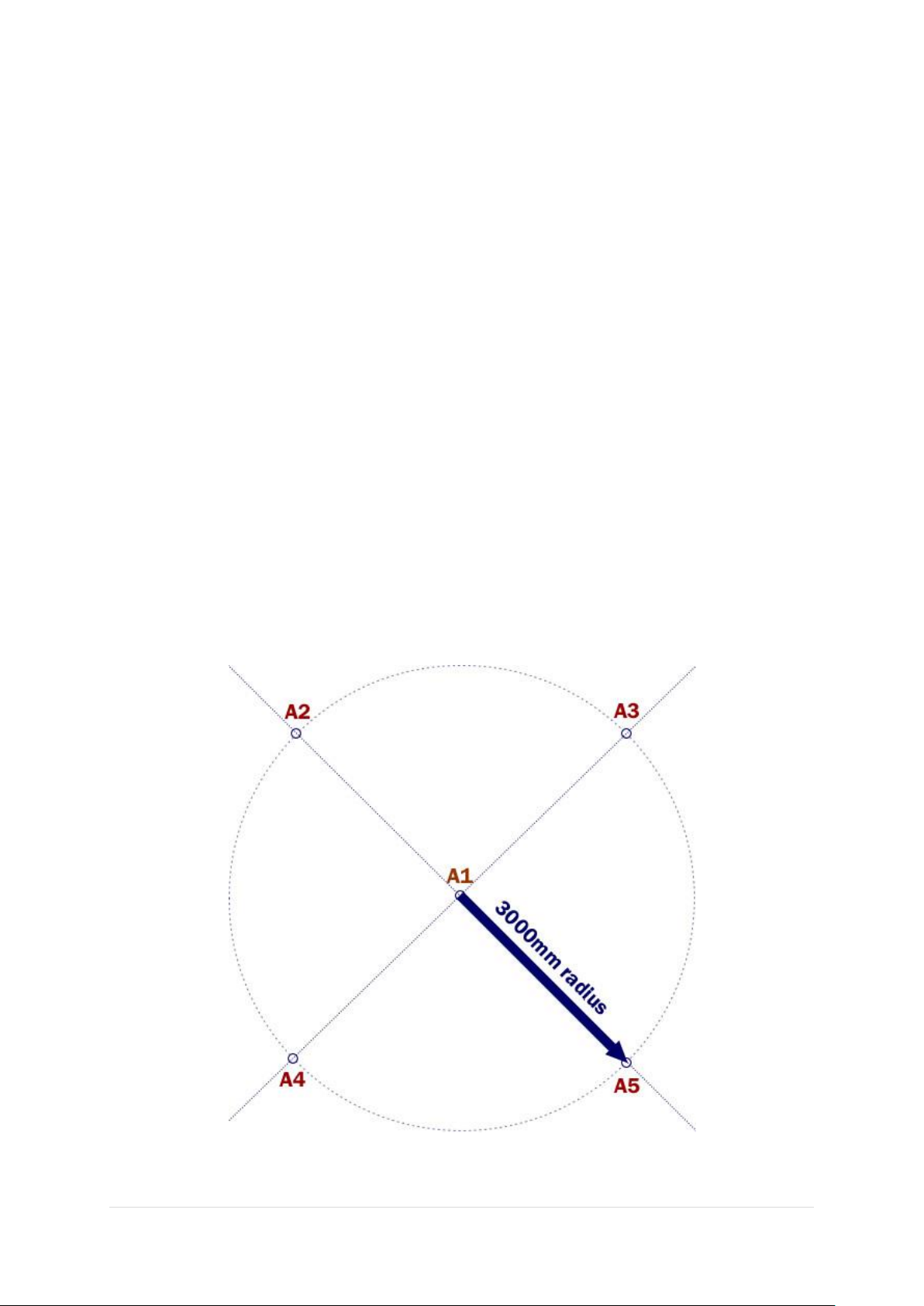
Step 1 – Setting out
Once you are happy with your chosen location, start marking out the position of the Spirafix ground
anchors. Cut a piece of string, make a loop in one end and trim it so it was the radius of the circle for
the four, peripheral anchors (3m long). If space is a little limited and the ground uneven the piece of
string is also ideal for finding the best location for the central anchor. Do this by attaching one end to
a stake that represents the central anchor (A1) and walk the circle whilst holding the end.
6 | P a g e
 Loading...