

Future Mobility Healthcare Inc. Orion II 500 Owner's Operation Manual
Owner’s Operations Manual
HEAVY DUTY ORION II 500
Future Mobility Healthcare Inc.
905 671-1661 – 1 888 737-4011
e-mail: customersupport@future-mobility.com
Future Mobility Healthcare Inc., 3223 Orlando Drive, Mississauga, ON L4V 1C5 – 905 671-1661 – 1 888 737-4011 – Fax: 905 671-3377
1010390 REV B – FMHI 2009 Page 1
3223 Orlando Drive
Mississauga, ON L4V 1C5
Fax: 1-888-670-3377
www.future-mobility.com
Innovative seating and mobility solutions

Orion II 500
NOTE:
WARNING
NOTICE
In case of damage, do NOT use the equipment.
Contact the Equipment Supplier for further instructions.
understand these instructions, contact a healthcare professional,
Information contained within this document is subject to change
Operating Instructions
Check all parts for shipping damages before using.
DO NOT install this equipment without first reading and
understanding this instruction booklet. If you are unable to
dealer or technical personnel before attempting to install this
equipment - otherwise, injury or damage may occur.
OPERATING SAFETY WARNINGS
Please read and obey all instructions and warnings listed in this manual, ignoring
these warnings could result in serious injury to the patient or attendants.
Ensure anti-tippers are always installed in the correct position when using the wheelchair.
Never lift the wheelchair by the armrests or front rigging.
Any change of seat depth may require repositioning of the rear wheels, always test the
stability of the chair before use.
Never stand on the footplates during transfers in and out of the wheelchair.
Ensure wheel locks are fully engaged while stopped on any incline/decline and while
patient is transferring to and from the wheelchair.
Never tilt the wheelchair on two wheels without assistance. When in any tilt or recline
position, this chair must be operated by an attendant.
Never use the wheel locks to stop a moving wheelchair.
It is not recommended to transport users in vehicles of any kind while seated in the
wheelchair. Do not use any kind of wheelchair Tie-Down restraints that are not approved
by Transport Canada.
Future Mobility Healthcare Inc., 3223 Orlando Drive, Mississauga, ON L4V 1C5 – 905 671-1661 – 1 888 737-4011 – Fax: 905 671-3377
1010390 REV B – FMHI 2009 Page 2

ORION II 500 STANDARD FEATURES
SPECIFICATIONS:
• Tilt Function (25 Degrees)
• 24” – 32” wide
• 15” – 22” depth
• Stroller Push Bar
• Fixed Height Full-Length Arms
2-Point Fixed
Height of 9-1/2”
Arm location for Tray Placement
• Fixed Back angle adjustable (+7 to -21 degrees)
• 16-1/2” STF
• 12”, 20” ,22” or 24” Rear wheels
• 5”, 6” or 8” Casters
• Multi-adjustable Axle Plate
• 70 Degree Front Rigging with Footplate
• Heel Loops
• Spring Back Push to Lock Wheel Locks
• Aluminium Seat Pan
• PRISM™ Ideal Cushion
• Adjustable Orion Back
• Two-Way, Padded, Contoured Headrest
• “Anti-rattle” rear Anti-Tippers
• Choice of 2 spirited colours
* User Weight limit: 500 lbs
Tilt Range: 3 - 28 degrees
Fixed Back Angle adjustment: +7 to -21 degrees
Overall Dimensions
(26” x 18” tilt, 16 1/2” STF)
Chair Width: 35”
Chair Length: 49” (with footboard)
Chair Height: 39”
Chair Weight: 70 lbs. (not including cushion,
back, arm rests and front riggings)
Future Mobility Healthcare Inc., 3223 Orlando Drive, Mississauga, ON L4V 1C5 – 905 671-1661 – 1 888 737-4011 – Fax: 905 671-3377
1010390 REV B – FMHI 2009 Page 3

OVERALL MAINTENANCE
1. Make sure all nuts and bolts are tight before operating the wheelchair
2. Make adjustments to the wheel locks to coincide with tire wear.
3. Inspect gas cylinders for leaks or wear and replace if required.
4. Inspect all cables and insure they are free from kinks and operate freely.
5. Wash and wax wheelchair to keep it free from excessive dirt and grease that might
interfere with the operation of the chair.
Transporting the Wheelchair
1. Remove the seating system.
2. Turn the anti-tippers to the upward position.
3. Remove the front rigging.
4. Remove the armrests.
5. Remove rear wheels (if necessary).
OPERATING INSTRUCTIONS
WARNING
After ANY adjustments, repair or service and BEFORE use, make sure all attaching
hardware is tightened securely – otherwise injury or damage may occur. Most operations
MUST be performed by a qualified technician. The operations described pertain to both
sides of the wheelchair. For example if one changes the height of the T-Style Arm Rest on
one side of the chair, the same should be done to the other side if required.
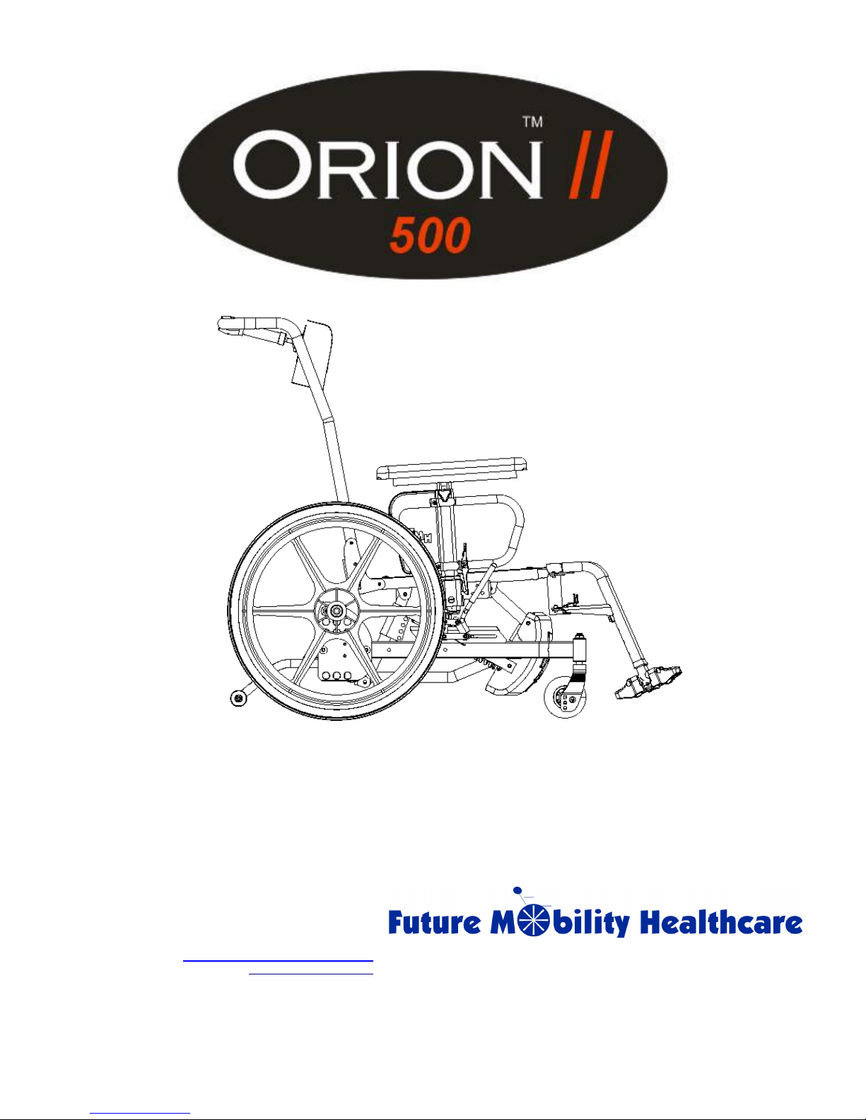
T-Style Arm Rests
(refer to Figure 1a)
Installing and removing T-style Armrest
1. Push armrest into arm socket until lock is engaged into slot.
2. For removal, push and hold release lever (`A'), while lifting armrest from arm socket.
Frame Adjustment Position
1. Remove armrest from the chair.
2. Remove the three inside bolts holding the arm socket to the seat frame (`B').
3. Move the arm socket to the forward mounting position (‘C') and replace the three bolts
('B').
4. Re-install the armrest in the arm socket.
Arm Height Adjustment
1. Loosen knob (`D').
2. Lift armrest until desired position is acquired (ranges from 9 ½” – 14” in ½” increments).
3. “Re-tighten” knob (‘D’).
Future Mobility Healthcare Inc., 3223 Orlando Drive, Mississauga, ON L4V 1C5 – 905 671-1661 – 1 888 737-4011 – Fax: 905 671-3377
1010390 REV B – FMHI 2009 Page 4
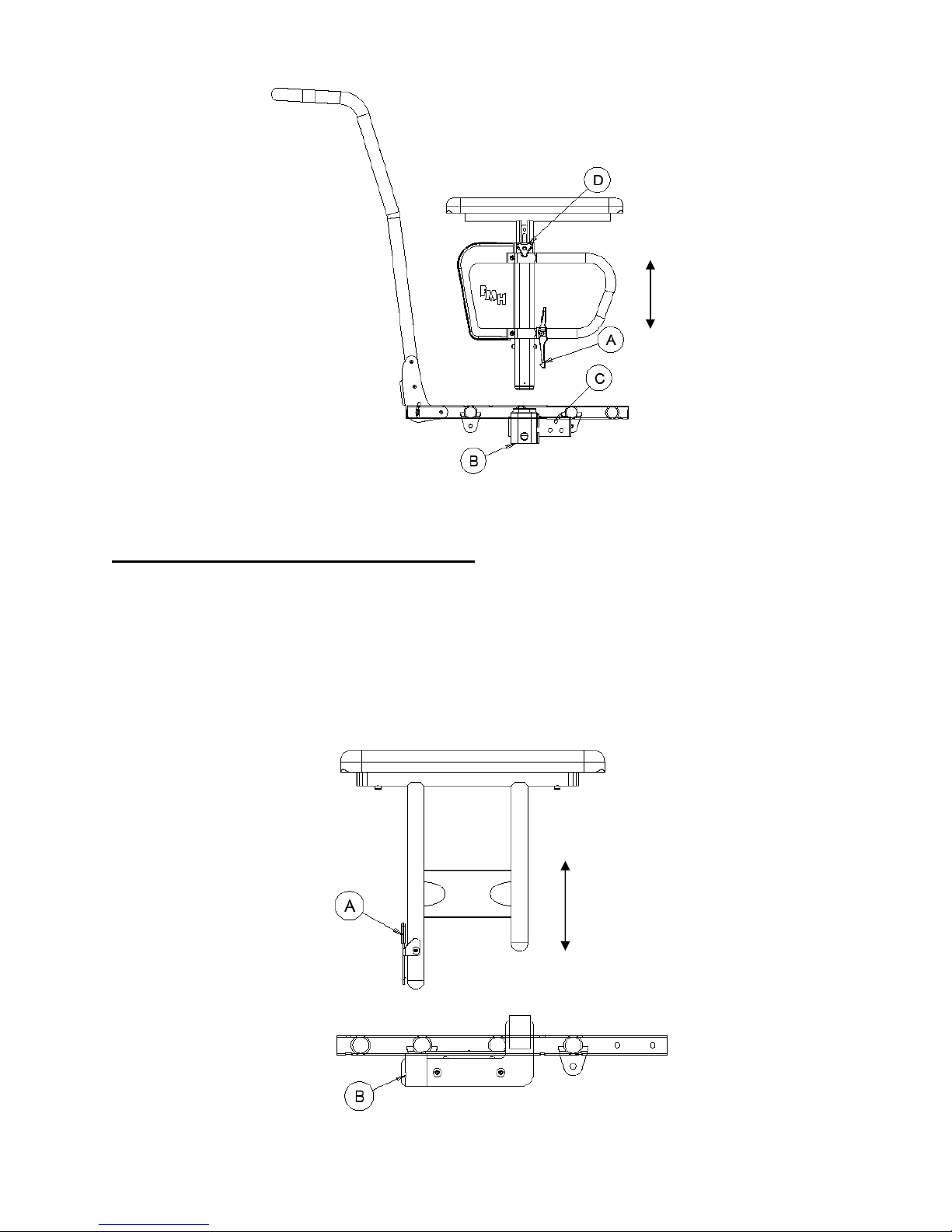
Figure 1a
2-Point Heavy Duty Arm Rests
(refer to Figure 1b)
Installing and removing 2-Point Heavy Duty Armrest
1. Push armrest into 2-point mounting bracket until lock is engaged into hole (‘B’)
2. For removal, push and hold release lever (`A'), while lifting armrest from 2-point
mounting plate
Note: The 2-point Heavy Duty Arm Rest is not adjustable in height
Future Mobility Healthcare Inc., 3223 Orlando Drive, Mississauga, ON L4V 1C5 – 905 671-1661 – 1 888 737-4011 – Fax: 905 671-3377
1010390 REV B – FMHI 2009 Page 5
Figure 1b
 Loading...