

Future Mobility Healthcare Inc. Capella Operation Manual
Operating Instructions
3223 Orlando Drive, Mississauga, ON L4V 1C5 – 905 671-1661 – 1 888 737-4011 – Fax: 905 671-3377
Future Mobility Healthcare Inc. - www.future-mobility.com. Orion and Prism are trademarks of Future Mobility Healthcare
Rev 2
Page 1

Capella
NOTE:
WARNING
NOTICE
without notice.
Operating Instructions
Check all parts for shipping damages before using.
In case of damage, do NOT use the equipment.
Contact the Equipment Supplier for further instructions.
DO NOT install this equipment without first reading and
understanding this instruction booklet. If you are unable to
understand these instructions, contact a healthcare professional,
dealer or technical personnel before attempting to install this
equipment - otherwise, injury or damage may occur.
Information contained within this document is subject to change
OPERATING SAFETY WARNINGS
Please read and obey all instructions and warnings listed in this manual, ignoring
these warnings could result in serious injury to the patient or attendants.
Ensure anti-tippers are always installed in the correct position when using the wheelchair.
Never lift the wheelchair by the armrests or front rigging.
Any change of seat depth may require repositioning of the rear wheels, always test the
stability of the chair before use.
Never stand on the footplates during transfers in and out of the wheelchair.
Ensure wheel locks are fully engaged while stopped on any incline/decline and while
patient is transferring to and from the wheelchair.
Never tilt the wheelchair on two wheels without assistance. When in any tilt or recline
position, this chair must be operated by an attendant.
Never use the wheel locks to stop a moving wheelchair.
It is not recommended to transport users in vehicles of any kind while seated in the
wheelchair. Do not use any kind of wheelchair Tie-Down restraints that are not approved
by the FDA.
3223 Orlando Drive, Mississauga, ON L4V 1C5 – 905 671-1661 – 1 888 737-4011 – Fax: 905 671-3377
Future Mobility Healthcare Inc. - www.future-mobility.com. Orion and Prism are trademarks of Future Mobility Healthcare
Rev 2
Page 2

SPECIFICATIONS:
CAPELLA STANDARD FEATURES
• Tilt Function (17 Degrees)
• 16” – 19” wide
• 15” – 19” depth
• Stroller Bar Low Fixed Back
• Fixed Height Full-Length Arms
Height of 9 ½”
• 16” STF
Lap Tray placement
• 20” Rear wheels
• 6” Casters
• Adjustable Axle Plate
• 70 Degree Upgraded Dual Swingaway Front Rigging
with Footplate
• Spring Back Push to Lock Wheel Locks
• Choice of 8 spirited colors ( Black, Blue, Green,
Orange, Purple, Red, Silver, Yellow)
* User Weight limit: 350 lbs
Tilt Range: 3 - 20 degrees
Overall Dimensions
(18""x 16" tilt , 16” STF)
Chair Width: 28.75"
Chair Length: 31"
Chair Height: 32"
Chair Weight: 40 Lbs.
(without seat pan, front riggings, wheels,
anti tippers and armrests)
3223 Orlando Drive, Mississauga, ON L4V 1C5 – 905 671-1661 – 1 888 737-4011 – Fax: 905 671-3377
Future Mobility Healthcare Inc. - www.future-mobility.com. Orion and Prism are trademarks of Future Mobility Healthcare
Rev 2
Page 3

SAFETY INSPECTION CHECKLIST
Item
Initially
Weekly
Monthly
Periodically
GENERAL
FRAME AND CROSSING TUBES
WHEEL LOCKS
SEAT AND BACK
TIRES
REAR WHEELS
HANDRIMS
FRONT CASTERS/FORKS
CLEANING
Initial adjustments should be made to suit your personal body structure needs and preference. Thereafter
follow these maintenance procedures:
• Wheelchair rolls straight (no excessive drag or
pull to one side)
• Inspect for loose or missing hardware
• Inspect for bent frame or crosstubes
• Do not interfere with tires when rolling
• Pivot points free of wear and looseness
• Wheel locks easy to engage
• Wheel locks prevent chair from moving when
engaged
• Inspect for rips or sagging
• Inspect for loose or broken hardware
• Inspect cane and hand grips for
wear/looseness
• Inspect for flat spots, cracks and wear
Caution: as with any vehicle, the wheels and
tires should be checked periodically for cracks
and wear and should be replaced.
• If equipped, quick-release axles lock properly
• No excessive side movement or binding when
lifted and spun
• Inspect for cracked, bent or broken spokes
• Inspect for signs of rough edges or peeling
• Inspect caster fork assembly for proper
tension by spinning caster; caster should
come to a gradual stop
• Adjust bearing system if wheel wobbles or
binds to a stop. Ensure wheel bearings are
clean and free of moisture.
• Check stem caster journal and lock nut for
tightness
• Inspect casters for cracks and wear
• Inspect for cracked, bent or broken spokes
• Clean upholstery and armrests
X
X
X
X
X
X
X
X
X
X
X
X
X
X
X
X
X
X
X
X
X
X
X
X
X
X
X
X
X
X
X
X
X
X
X
X
X
X
X
X
X
X
X
X
3223 Orlando Drive, Mississauga, ON L4V 1C5 – 905 671-1661 – 1 888 737-4011 – Fax: 905 671-3377
Future Mobility Healthcare Inc. - www.future-mobility.com. Orion and Prism are trademarks of Future Mobility Healthcare
Rev 2
Page 4
TROUBLESHOOTING
Chair
Capeela
Sluggish
Caster
Squeaks
Looseness
Solution
s
WEIGHT CAPACITY
WARNING
TILT
USE CAUTION
Veers
Right/Left
X X X
X X
Wheels
Turn or
Performance
X X X X
Check that rear wheels
Flutter
and
Rattles
Check angle adjustable
CAPELLA LABELS
350 LBS. (159 kgs)
REFER TO OWNER’S MANUAL
DO NOT OPERATE WITHOUT
THE ANTI-TIP MECHANISM
IN PLACE
OPERATING INSTRUCTIONS
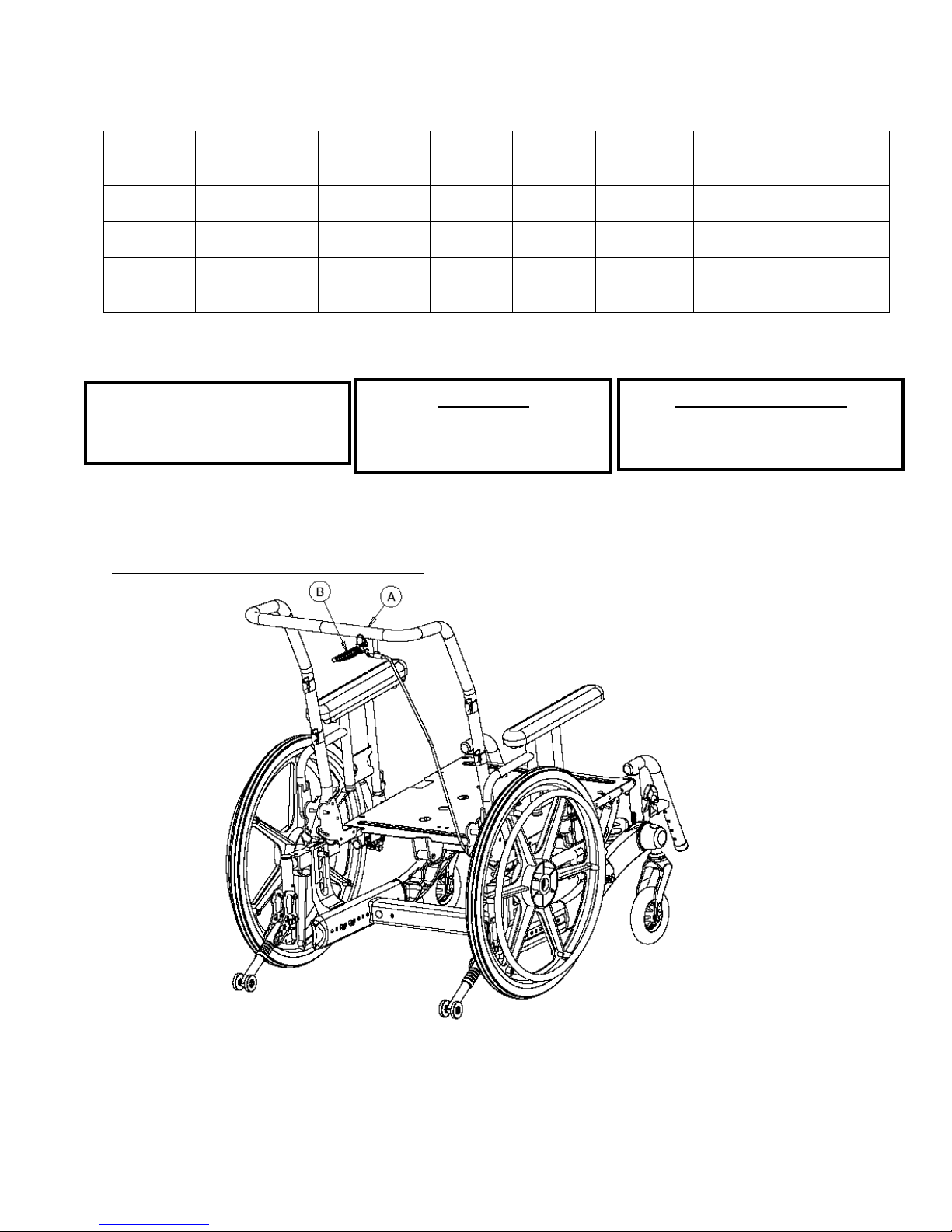
Activating the Tilt Mechanism (refer to Figure 1)
in Chair
Check for loose nuts and
bolts
caster assembly
are equally spaced away
from seat frame.
WHEN PROPELLING THIS CHAIR
IN THE TILT POSITION. USER
WEIGHT 350 LBS MAXIMUM
3223 Orlando Drive, Mississauga, ON L4V 1C5 – 905 671-1661 – 1 888 737-4011 – Fax: 905 671-3377
Future Mobility Healthcare Inc. - www.future-mobility.com. Orion and Prism are trademarks of Future Mobility Healthcare
Rev 2
Figure 1
Page 5

1. Grasp the tilt handle (‘B’) located on the stroller handle (‘A’)
2. Pull up on handle to release the wheelchair from the ‘locked’ position and gently push
down on the stroller handle to tilt the chair.
3. When the chair tilts to the desired angle, release the tilt handle and the chair will ‘lock’ in
place at the specific angle.
4. To return the wheelchair to the nominal ‘zero’ position grasp the tilt handle and pull up on
the stroller handle to tilt the chair.
5. Release the tilt handle when the wheelchair reaches the desired angle.
T-Style Fixed Arm Rests
(refer to Figure 2a)
Installing and removing T-Style Fixed Armrest
1. Push armrest into the armrest base until lock is engaged into slot (‘A’)
2. For removal, push and hold release lever (`B'), while lifting armrest from the armrest base
Note: The T-Style Fixed Arm Rest is not adjustable in height
T-Style Arm Rests – Pin Release
ADJUSTING T-STYLE ARM HEIGHT
1. Swing out the height adjustment latch lever to disengage the holding pin.
2. Lift armrest until desired position is acquired (ranges from 9’’– 13” in ½” increments).
3. Swing in the height adjustment latch lever to engage the holding pin.
4. Repeat this procedure for the opposite T-style arm assembly.
3223 Orlando Drive, Mississauga, ON L4V 1C5 – 905 671-1661 – 1 888 737-4011 – Fax: 905 671-3377
Future Mobility Healthcare Inc. - www.future-mobility.com. Orion and Prism are trademarks of Future Mobility Healthcare
Rev 2
Figure 2a
(refer to Figure 2b)
Page 6
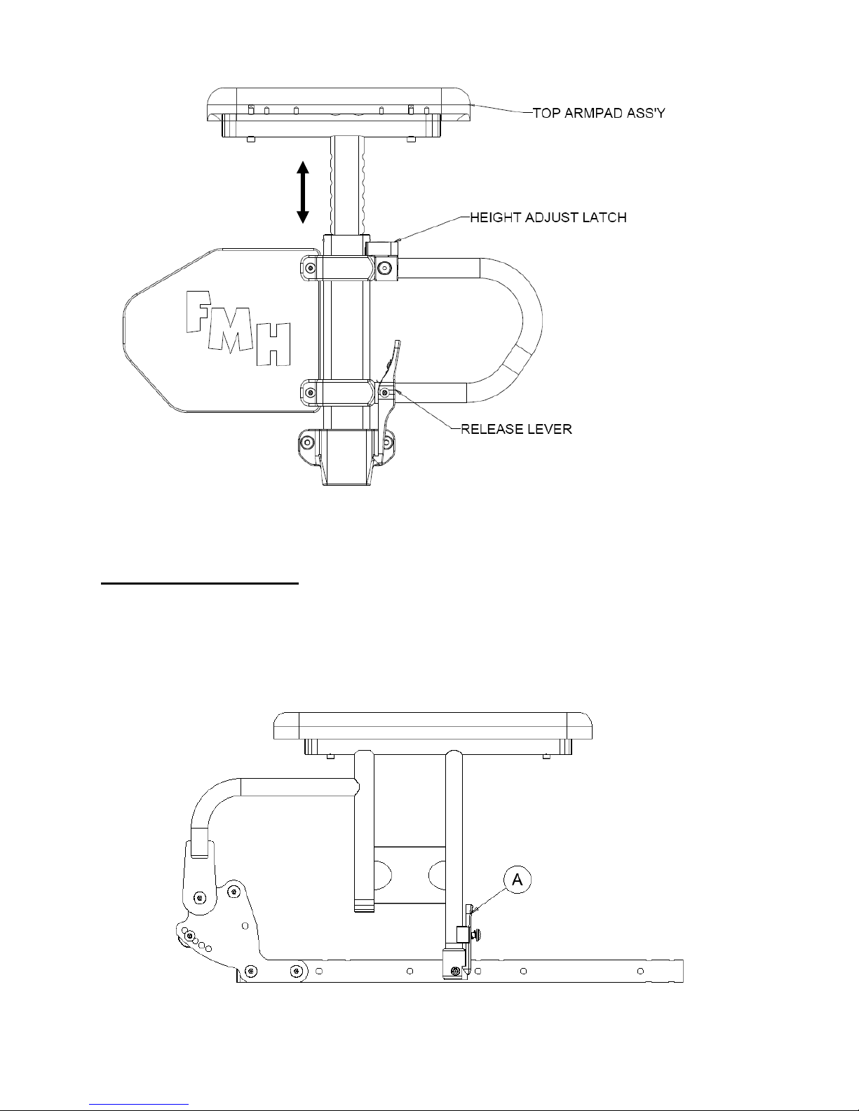
Figure 2b
Flip-up Arm Rests
(refer to Figure 2c)
Engaging and Disengaging Flip-up style armrest
1. To engage, push armrest into arm socket until release lever (‘A’) is engaged into slot.
2. For flip-up, push and hold release lever (`A'), while lifting armrest from arm socket.
Figure 2c
3223 Orlando Drive, Mississauga, ON L4V 1C5 – 905 671-1661 – 1 888 737-4011 – Fax: 905 671-3377
Future Mobility Healthcare Inc. - www.future-mobility.com. Orion and Prism are trademarks of Future Mobility Healthcare
Rev 2
Page 7
 Loading...