

Future Mobility Prism BASIC, Prism ULTRA, Prism TRUEFITT, Prism SUPER BACK, Prism AIR BACK User Manual

PRISM BACKS
(BASIC, ULTRA, TRUEFITT, AIR BACK AND SUPER BACK FOR KIDS)
850 REV04 REV DATE: 09/03/2014 Page 1 of 16
850 REV04 REV DATE: 09/03/2014

Table of Contents
Page 3 1.0 Hardware Kit Contents
Page 3
Page 4-5 3.0 Before Installation
Page 5-9 4.0 Prism Universal
Hardware Installation
2.0 Tools Required
Instructions
Page 10 5.0 Disengaging the Prism Back
Page 11 6.0 Head/ Neck Support Attachment
Page 12
Page 12 8.0 Air Back
7.0 True Fit Back
Page 13 9.0 Maintenance
Page 14 10.0 Warranty
Page 15 Warranty Registration Form
850 REV04 REV DATE: 09/03/2014 Page 2 of 16

Mounting pins on the chair
back
Adjustable mount plate
Clamp mounting
screws
Cane clamp front
Back plate
Cane clamp insert
1.0 Hardware Kit Contents
1- Back mounting Plate LT
1- Back mounting Plate RT
2 - Cane Clamps
4 - Cane Inserts
6 - Depth/Recline Adjustment Screws
6 - Cane Clamp Screws
2 - Backing Plate
2.0 Tools Required
Wrench: 1/2”
Allen Key:
3/16”
Tape Measure / Ruler
850 REV04 REV DATE: 09/03/2014 Page 3 of 16

3.0 Before Installation
! PLEASE NOTE
When establishing the mounting position for
the Prism mounting Hardware, please insure
the stability of the wheelchair is not
compromised.
Adjusting the forward and aft position of the
backrest will alter the user‘s center of gravity within
the wheelchair. A recessed back position can
significantly reduce the rearward stability of the
wheelchair. Similarly, a more forward back position
will reduce the wheelchair’s forward stability.
The Back Mounting Plates and the Cane Clamps are shipped pre-assembled
with the hardware oriented in the forward most back position (see Fig. 1
below). By altering the orientation of the Cane Clamps with the Back
mounting Plates, the hardware can be positioned to provide a rear most
mounting position for the back if desired (see Fig. 2 below).
To make the adjustment from the forward most to the rearmost position
(or vice versa), detach the Back Mounting Plates from each Cane Clamp by
removing the 3 Depth/Recline Adjustment Screws. Then turn the Cane
Clamp 180° and re-attach it to the Mounting Plate in its original orientation.
The Prism Hardware offers users a full 5” range of forward and rear
adjustability (Angle adjustment forward 15°, back 20°).
Each mounting plate provides an individual adjustment range of 1.5”.
Front of Fig. 1 Front of Fig. 2
Wheelchair Wheelchair
Back Mounting Plate in the Back Mounting Plate in the
Forward most back position rear most back position
850 REV04 REV DATE: 09/03/2014 Page 4 of 16

Cane clamp
Cane clamp
Cane insert
3.0 Before Installation
The Cane Clamps is designed to fit 1” diameter wheelchair back posts.
Santoprene Cane Inserts are provided, which can be placed inside the Cane
Clamps to allow the back to be installed onto 7/8” wheelchair back posts (see
Fig. 3 below).
Fig. 3
4.0 Prism Back Installation Instructions
1. Determine the appropriate Back mounting Plate set-up/ configuration for
the user (per Section 3.0).
2. Loosen the Cane Clamp Screws (3 per clamp) in order to open the clamp
enough to fit around the back posts (Install clamps inserts if required).
3. Starting on one side, position the Cane Clamp at the desire height on the
back post and tighten the clamp screws enough to hold it in place.( Clamps
will be fully secured ones the back is installed and all final adjustments are
made) .
4. Using a ruler, measure the exact height of the installed cane Clamp from a
fixed point on the wheelchair, and install the second Cane Clamp at
the same height on the opposite back post (see Fig. 4 below). Please
ensure the Cane Clamps are also mounted parallel with each other.
850 REV04 REV DATE: 09/03/2014 Page 5 of 16

Note:
Check all parts for shipping damages before using. In
case of damage, DO NOT use the equipment. Contact the
Equipment Supplier for further instructions.
Warning:
DO NOT install this equipment without first reading and
understanding this instruction booklet. If you are unable
to understand these instructions, contact a healthcare
professional , dealer or technical personnel before attempting
to install this equipment- otherwise, injury or
damage may occur
Notice:
Information contained within this document is subject to
change without notice.
850 REV04 REV DATE: 09/03/2014 Page 6 of 16

4.0 Prism Back Installation Instructions
Fig. 4
Cane Clamps
Install Cane Clamps
at equal heights and
parallel to each other
! PLEASE NOTE
Additional upper and lower
adjustment slots are provided
on the Prism Hardware Back
Mounting Plates to allow alternate
mounting heights when
back post obstacles are encountered.
Using the Alternate
Mounting Slots will increase or
decrease the back heights by
7/8”. However using the lower
slot will decrease the range of
available depth and angle
adjustment
Upper
Adjustment
slot
Lower
Adjustment
slot
Back
Mounting
Plate
850 REV04 REV DATE: 09/03/2014 Page 7 of 16
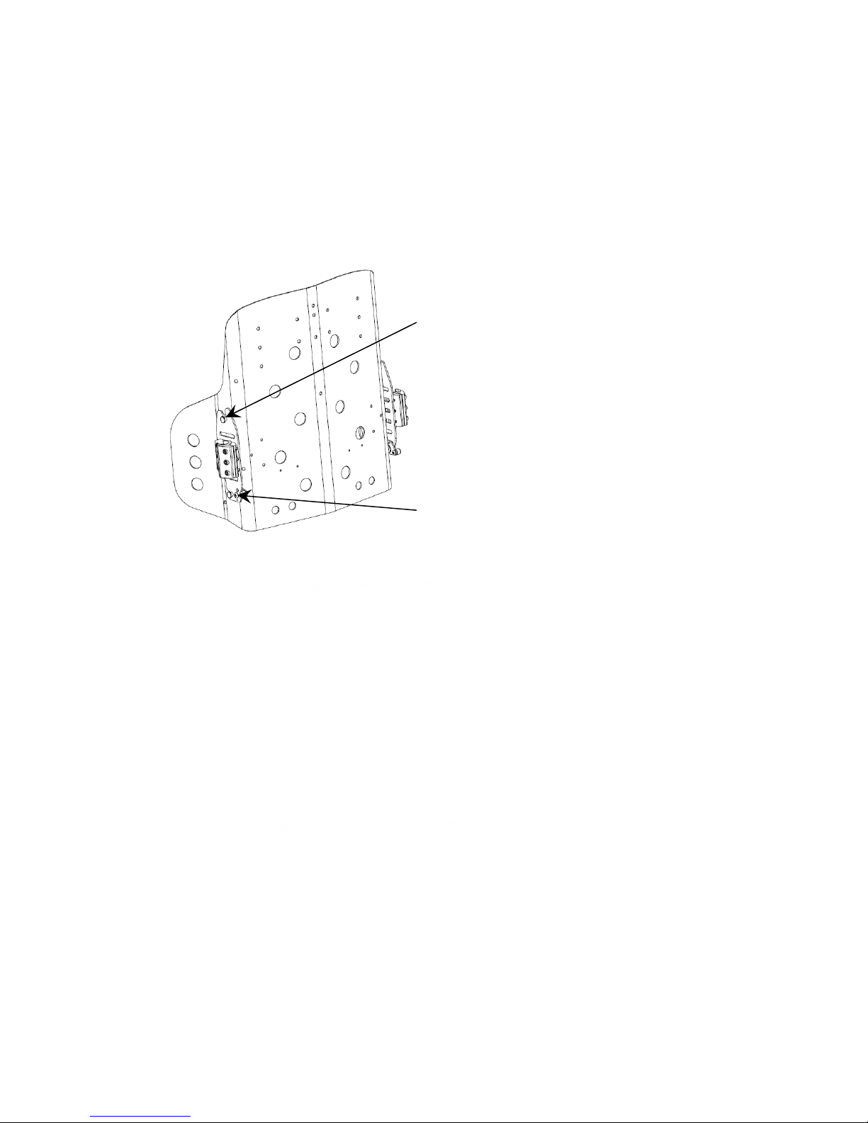
UPPER MOUNTING PIN
LOWER MOUNTING PIN
4.0 Prism Back Installation Instructions
5. To Install the Prism Back onto the back mounting plates please refer to the
Instructions and diagram (see Fig. 5 below).
Step 1: Insert the upper mounting plate into hooked slot on the top of
the back mounting plates.
Step 2: Ensure that the LT detent latch is in the closed position.
Step 3: With the upper pins in place, snap lower pins into the latch mechanism
at the bottom of the back mounting plates.
6. In order to install the longer Mounting Pins, first remove the outer cover
from the back.
! PLEASE NOTE
Our Standard Prism Back can be adjusted to accommodate wheelchair seat frame sizes up to 2”
wider than the actual back width. Each Prism Back is shipped with the standard mounting pins
installed. A set of longer pins for 1” wider and 2” wider seat frames can be purchased separately.
850 REV04 REV DATE: 09/03/2014 Page 8 of 16

4.0 Prism Back Installation Instructions
7. To install the longer mounting pins, please refer to the instructions bellow
• Remove the back from the wheelchair and secure in place.
• Using wrench, loosen the inside nut and replace standard pins to
the longer pins
• Carefully tighten nuts to secure the pins in place.
Ensure the pins do not rotate when tightening nuts.
Standard Mounting Pin
1/2” Longer Mounting Pin
Standard Mounting 1” Longer Mounting Pin
Pins
Prism Back Front View
8. Check that the fit and alignment of the back is correct
9. Fully tighten the Cane Clamp Screws on each side of the back
10. Once the back is properly secured to the back canes, the user can be
seated in the wheelchair in order to establish the optimal depth and
recline settings for the back. With the user in the chair, loosen the
Depth/Recline Adjustment Screws, position the back at the desired
depth and recline angle, and re-tighten the screws to lock in place.
850 REV04 REV DATE: 09/03/2014 Page 9 of 16

5.0 Disengaging the Prism Back
To Disengage the Back from the wheelchair:
1. Push the release lever downwards on the left mounting plate until the ball
plunger engages the latch open position.
2. Push the release lever on the right mounting plate.
3. Lower mounting pins will automatically ejected from the mounting plates
(See Fig. 6 below)
4. Once the lower pins are released, lift the back up and out of the upper slots
on the mounting plates.
850 REV04 REV DATE: 09/03/2014 Page 10 of 16
Fig. 6

6.0 Head/Neck Mounting Support
The Prism Backs have (3) sets of holes on the top edge of the shell where
the Headrest Adaptor Bracket attaches to the shell. With the Universal
Adaptor bracket, most standard types of headrest can be mounted.
Instructions for installing a Headrest clamp:
1. Open outer cover and determine which set of holes to use to attach the
adaptor bracket. The Bracket may be shifted 1.5” left or right
depending on the user requirements.
2. Close the cover and carefully punch (2) holes through the cover fabric that
match the determined mounting holes.
3. Open the front of the cover to access the appropriate mounting holes.
4. Push the mounting screws outward through the back shell and fabric.
Place the Headrest Clamp with locknuts in-line with screws on the
outside of the back cover.
5. Tighten both screws and close the cover.
850 REV04 REV DATE: 09/03/2014 Page 11 of 16

7.0 PRISM True Fit Back
Please follow the instructions within this booklet to: determine mounting
position of Back, install hardware; mount, install and remove Back; and set
up back angle of the PRISM True Fit Back.
Customization of foam cubes
1. Remove cover and outer foam pad from shell.
2. Install shell on chair and mark the foam cubes to be trimmed
based on clients requirements.
3. Remove the foam blocks to be modified from the shell (foam is secured
using hook and loop fastener).
4. Bend the foam block at the space next to the cube to be cut or carved.
5. Trim each cube to the desired length using a sharp knife or scissors (foam
cutting saw works best).
6. Reinstall trimmed foam blocks onto the aluminium shell.
7. Replace outer foam pad and cover.
8.0 PRISM Air Back
1. Installation procedure is identical to other Prism Back models (see above).
To Adjust Air Inserts
1. Unzip cover, fold both flaps back, separate foam pad from shell and gently
remove air bladder from back panel (insert is held in place with hook and
loop fasteners). Reposition to desired height, reattach hook and loop
fastener and zip cover.
2. Inflate lumbar and lateral inserts by squeezing bulb valve until positioning is
attained. Remove air from insert by pressing button on bulb valve.
850 REV04 REV DATE: 09/03/2014 Page 12 of 16

9.0 Maintenance
Cleaning Instructions
Back Assembly
Clean with a dampened cloth on a regular basic depending on usage.
Wipe entre surface.
! PLEASE NOTE
Visual inspection of all parts, mounting assemblies, foam and upholstery
materials
for any deformation, corrosion, breakage or wear is recommended. Check
all fasteners on a regular basic to ensure that all connections remain secure.
Cover
USE mild detergent and machine -wash cold using gentle cycle. DO NOT
USE fabric softeners or bleach. DO NOT machine dry -air dry in shady
area.
! PLEASE NOTE
The cover is designed to protect the foam against a user’s incontinence
and to be fire retardant, so the Prism Back’s must not be used without
their covers. If the cover is torn, it must be replaced.
Foam
If the Prism Back foam becomes contaminated due to incontinence, the
foam pad can be replaced independently. Foam can be purchased separately
by ordering through Future Mobility Products’ Customer Service.
850 REV04 REV DATE: 09/03/2014 Page 13 of 16

10.0 WARRANTY
This warranty is extended only to the original purchaser/user of our products.
Future Mobility Healthcare Inc. warrants its positioning products to be free from
defects in materials and workmanship for two (2) years on backs, one (1) year
on hardware and 90 days on covers, upon normal usage by original purchaser.
If within this warranty period the product shall be proven to be defective, such
product shall be repaired or replaced, at Future Mobility Healthcare Inc. discretion.
Future Mobility Healthcare Inc. sole obligation and your exclusive remedy
under this warranty shall be limited to the repair and/or replacement of the product
or its parts. This warranty does not include any labor or shipping charges
incurred in replacement part installation or repair of any product.
For warranty service, please contact the dealer from whom you purchased your
Future Mobility Healthcare Inc. product. In the event you do not receive satisfactory
warranty service, please write directly to Future Mobility Healthcare Inc.
at 3223 Orlando Drive, Mississauga, Ontario, L4V 1C5. Provide the dealer’s
name, address, model number, and date of purchase and indicate the nature of
the defect.
DO NOT return products to Future Mobility Healthcare Inc. without our prior
consent. The defective unit or parts must be returned for warranty inspection
within thirty (30) days of the return authorization date. (Future Mobility Healthcare
Inc. will issue a return authorization number). Please prepay all shipping
charges; C.O.D. shipments will be refused.
LIMITATIONS and EXCLUSIONS: This warranty shall not apply to problems
arising from normal wear or failure to adhere to the enclosed instructions. Products
subjected to negligence, accident, improper usage, maintenance or storage;
or products modified without Future Mobility Healthcare Inc. written consent
including, but not limited to: modification through the use of any unauthorized
parts or attachments; products damaged by reason or repairs made to any
component without the specific consent of Future Mobility Healthcare Inc. or
products repaired by anyone other than a Future Mobility Healthcare Inc.
dealer. Such evaluation shall be determined by Future Mobility Healthcare Inc.
The foregoing warranty is exclusive and in lieu of all other expressed warranties.
It shall not extend beyond the duration of the expressed warranty provided
herein and the remedy for violations of any implied warranty shall be limited to
repair or replacement of the defective product pursuant to the terms contained
herein. Future Mobility Healthcare Inc. shall not be liable for any consequential
or incidental damages whatsoever.
This warranty shall be extended to comply with all provincial laws and requirements.
850 REV04 REV DATE: 09/03/2014 Page 14 of 16

Cut below this line
Warranty Registration Form
To validate your Future Mobility HealthCare warranty, please complete the below form and
return it the address at the end of this form. Visit online at www.futuremobility.ca for more
Future Mobility Products.
Name: ____________________________
Street Address: _________________________________________________
City/Country/Postal Code: ________________________________________
Telephone: _______________________________
Purchased Date: _______________________________
Purchased From (Dealer Name and Address):_________________________
Product Purchased: _____________________________________________
Serial Number: ___________________________________________
Print and Mail it to:
Future Mobility Healthcare Products
3223 Orlando Drive
Mississauga, Ontario, L4V 1C5
Fax: 905-671-3377
850 REV04 REV DATE: 09/03/2014 Page 15 of 16

850 REV04 REV DATE: 09/03/2014 Page 16 of 16
 Loading...