

Page 1

BEDIENUNGSANLEITUNG
USER MANUAL
PLB-280
Moving-Head
Spot/Beam
Für weiteren Gebrauch aufbewahren!
Keep this manual for future needs!
© Copyright
Nachdruck verboten!
Reproduction prohibited!
Page 2

Inhaltsverzeichnis
EINFÜHRUNG ................................................................................................................................................... 4
Lieferumfang .................................................................................................................................................. 4
SICHERHEITSHINWEISE ................................................................................................................................. 5
BESTIMMUNGSGEMÄSSE VERWENDUNG .................................................................................................. 6
GERÄTEBESCHREIBUNG .............................................................................................................................. 8
Features ......................................................................................................................................................... 8
Geräteübersicht .............................................................................................................................................. 9
INSTALLATION .............................................................................................................................................. 10
Lampeninstallation/Lampenwechsel ............................................................................................................ 10
Einsetzen/Austauschen von Gobos ............................................................................................................. 11
Projektormontage ......................................................................................................................................... 12
Einbau des optionalen drahtlos-Empfängers für WDMX-Betrieb (FUTURELIGHT WDR-G4) .................... 15
Anschluss an den DMX-512 Controller / Verbindung Projektor – Projektor ................................................ 16
Anschluss ans Netz ...................................................................................................................................... 17
BEDIENUNG ................................................................................................................................................... 17
Stand Alone-Betrieb ..................................................................................................................................... 17
DMX-gesteuerter Betrieb ............................................................................................................................. 17
Adressierung des Projektors ........................................................................................................................ 17
DMX-Protokoll .............................................................................................................................................. 18
Control Board ............................................................................................................................................... 27
Connect ........................................................................................................................................................ 29
Light ............................................................................................................................................................. 29
Information ................................................................................................................................................... 29
Set ................................................................................................................................................................ 30
Program ....................................................................................................................................................... 32
Fehlermeldungen ......................................................................................................................................... 34
REINIGUNG UND WARTUNG ........................................................................................................................ 34
Sicherungswechsel ...................................................................................................................................... 35
TECHNISCHE DATEN .................................................................................................................................... 36
KONFORMITÄT .............................................................................................................................................. 38
00092351, Version 1.1 2/72
Page 3

Table of contents
INTRODUCTION ............................................................................................................................................. 39
Delivery includes .......................................................................................................................................... 39
SAFETY INSTRUCTIONS .............................................................................................................................. 40
OPERATING DETERMINATIONS .................................................................................................................. 41
DESCRIPTION OF THE DEVICE ................................................................................................................... 43
Features ....................................................................................................................................................... 43
Overview ...................................................................................................................................................... 44
INSTALLATION .............................................................................................................................................. 45
Installing/Replacing the lamp ....................................................................................................................... 45
Inserting/Exchanging gobos ......................................................................................................................... 46
Rigging ......................................................................................................................................................... 47
Installation of the optional wireless receiver for WDMX-operation (FUTURELIGHT WDR-G4) .................. 50
DMX-512 connection / connection between fixtures .................................................................................... 51
Connection with the mains ........................................................................................................................... 52
OPERATION ................................................................................................................................................... 52
Stand Alone operation ................................................................................................................................. 52
DMX-controlled operation ............................................................................................................................ 52
Addressing ................................................................................................................................................... 52
DMX-protocol ............................................................................................................................................... 53
Control Board ............................................................................................................................................... 62
Connect ........................................................................................................................................................ 64
Light ............................................................................................................................................................. 64
Information ................................................................................................................................................... 64
Set ................................................................................................................................................................ 65
Program ....................................................................................................................................................... 67
Error Messages ............................................................................................................................................ 69
CLEANING AND MAINTENANCE ................................................................................................................. 69
Replacing the fuse ....................................................................................................................................... 70
TECHNICAL SPECIFICATIONS ..................................................................................................................... 71
Diese Bedienungsanleitung gilt für die Artikelnummer 51838966
This user manual is valid for the article number 51838966
Das neueste Update dieser Bedienungsanleitung finden Sie im Internet unter:
You can find the latest update of this user manual in the Internet under:
www.futurelight.com
00092351, Version 1.1 3/72
Page 4
BEDIENUNGSANLEITUNG
PLB-280 Moving-Head Spot/Beam
ACHTUNG!
Gerät vor Feuchtigkeit und Nässe schützen!
Vor Öffnen des Gerätes vom Netz trennen!
Lesen Sie vor der ersten Inbetriebnahme zur eigenen Sicherheit diese Bedienungsanleitung
sorgfältig durch!
Alle Personen, die mit der Aufstellung, Inbetriebnahme, Bedienung, Wartung und Instandhaltung dieses
Gerätes zu tun haben, müssen
- entsprechend qualifiziert sein
- diese Bedienungsanleitung genau beachten
- die Bedienungsanleitung als Teil des Produkts betrachten
- die Bedienungsanleitung während der Lebensdauer des Produkts behalten
- die Bedienungsanleitung an jeden nachfolgenden Besitzer oder Benutzer des Produkts weitergeben
- sich die letzte Version der Anleitung im Internet herunter laden
EINFÜHRUNG
Wir freuen uns, dass Sie sich für einen FUTURELIGHT PLB-280 entschieden haben. Sie haben hiermit ein
leistungsstarkes und vielseitiges Gerät erworben.
Nehmen Sie den PLB-280 aus der Verpackung.
Lieferumfang
1 Gerät
1 Bedienungsanleitung
1 Osram Sirius HRI 280 W (bereits installiert)
1 DMX-Kabel 3 m
1 PowerCon Netzkabel
1 MP-8 Adapterplatte
00092351, Version 1.1 4/72
Page 5

SICHERHEITSHINWEISE
ACHTUNG!
Seien Sie besonders vorsichtig beim Umgang mit gefährlicher Netzspannung. Bei dieser Spannung können Sie einen lebensgefährlichen elektrischen Schlag erhalten!
Dieses Gerät hat das Werk in sicherheitstechnisch einwandfreiem Zustand verlassen. Um diesen Zustand zu
erhalten und einen gefahrlosen Betrieb sicherzustellen, muss der Anwender die Sicherheitshinweise und die
Warnvermerke unbedingt beachten, die in dieser Bedienungsanleitung enthalten sind.
Unbedingt lesen:
Bei Schäden, die durch Nichtbeachtung der Anleitung verursacht werden, erlischt der Garantieanspruch. Für daraus resultierende Folgeschäden übernimmt der Hersteller keine Haftung.
Das Gerät darf nicht in Betrieb genommen werden, nachdem es von einem kalten in einen warmen Raum
gebracht wurde. Das dabei entstehende Kondenswasser kann unter Umständen Ihr Gerät zerstören. Lassen
Sie das Gerät solange uneingeschaltet, bis es Zimmertemperatur erreicht hat!
Bitte überprüfen Sie vor der ersten Inbetriebnahme, ob kein offensichtlicher Transportschaden vorliegt.
Sollten Sie Schäden an der Netzleitung oder am Gehäuse entdecken, nehmen Sie das Gerät nicht in Betrieb
und setzen sich bitte mit Ihrem Fachhändler in Verbindung.
Der Aufbau entspricht der Schutzklasse I. Der Netzstecker darf nur an eine Schutzkontakt-Steckdose
angeschlossen werden, deren Spannung und Frequenz mit dem Typenschild des Gerätes genau
übereinstimmt. Ungeeignete Spannungen und ungeeignete Steckdosen können zur Zerstörung des Gerätes
und zu tödlichen Stromschlägen führen.
Den Netzstecker immer als letztes einstecken. Der Netzstecker muss dabei gewaltfrei eingesetzt werden.
Achten Sie auf einen festen Sitz des Netzsteckers.
Lassen Sie die Netzleitung nicht mit anderen Kabeln in Kontakt kommen! Seien Sie vorsichtig beim Umgang
mit Netzleitungen und -anschlüssen. Fassen Sie diese Teile nie mit feuchten Händen an! Feuchte Hände
können tödliche Stromschläge zur Folge haben.
Netzleitungen nicht verändern, knicken, mechanisch belasten, durch Druck belasten, ziehen, erhitzen und
nicht in die Nähe von Hitze- oder Kältequellen bringen. Bei Missachtung kann es zu Beschädigungen der
Netzleitung, zu Brand oder zu tödlichen Stromschlägen kommen.
Die Kabeleinführung oder die Kupplung am Gerät dürfen nicht durch Zug belastet werden. Es muss stets
eine ausreichende Kabellänge zum Gerät hin vorhanden sein. Andernfalls kann das Kabel beschädigt
werden, was zu tödlichen Stromschlägen führen kann.
Achten Sie darauf, dass die Netzleitung nicht gequetscht oder durch scharfe Kanten beschädigt werden
kann. Überprüfen Sie das Gerät und die Netzleitung in regelmäßigen Abständen auf Beschädigungen.
Werden Verlängerungsleitungen verwendet muss sichergestellt werden, dass der Adernquerschnitt für die
benötigte Stromzufuhr des Gerätes zugelassen ist. Alle Warnhinweise für die Netzleitung gelten auch für
evtl. Verlängerungsleitungen.
Gerät bei Nichtbenutzung und vor jeder Reinigung vom Netz trennen! Fassen Sie dazu den Netzstecker an
der Grifffläche an und ziehen Sie niemals an der Netzleitung! Ansonsten kann das Kabel und der Stecker
beschädigt werden was zu tödlichen Stromschlägen führen kann. Sind Stecker oder Geräteschalter, z. B.
durch Einbau nicht erreichbar, so muss netzseitig eine allpolige Abschaltung vorgenommen werden.
Wenn der Netzstecker oder das Gerät staubig ist, dann muss es außer Betrieb genommen werden, der
Stromkreis muss allpolig unterbrochen werden und das Gerät mit einem trockenen Tuch gereinigt werden.
Staub kann die Isolation reduzieren, was zu tödlichen Stromschlägen führen kann. Stärkere Verschmutzungen im und am Gerät dürfen nur von einem Fachmann beseitigt werden.
00092351, Version 1.1 5/72
Page 6
Es dürfen unter keinen Umständen Flüssigkeiten aller Art in Steckdosen, Steckverbindungen oder in
irgendwelche Geräteöffnungen oder Geräteritzen eindringen. Besteht der Verdacht, dass - auch nur
minimale - Flüssigkeit in das Gerät eingedrungen sein könnte, muss das Gerät sofort allpolig vom Netz
getrennt werden. Dies gilt auch, wenn das Gerät hoher Luftfeuchtigkeit ausgesetzt war. Auch wenn das
Gerät scheinbar noch funktioniert, muss es von einem Fachmann überprüft werden ob durch den
Flüssigkeitseintritt eventuell Isolationen beeinträchtigt wurden. Reduzierte Isolationen können tödliche
Stromschläge hervorrufen.
In das Gerät dürfen keine fremden Gegenstände gelangen. Dies gilt insbesondere für Metallteile. Sollten
auch nur kleinste Metallteile wie Heft- und Büroklammern oder gröbere Metallspäne in das Gerät gelangen,
so ist das Gerät sofort außer Betrieb zu nehmen und allpolig vom Netz zu trennen. Durch Metallteile
hervorgerufene Fehlfunktionen und Kurzschlüsse können tödliche Verletzungen zur Folge haben.
Bei der ersten Inbetriebnahme kann es zu Rauch- und Geruchserzeugung kommen. Hierbei handelt es sich
nicht um eine Störung des Gerätes.
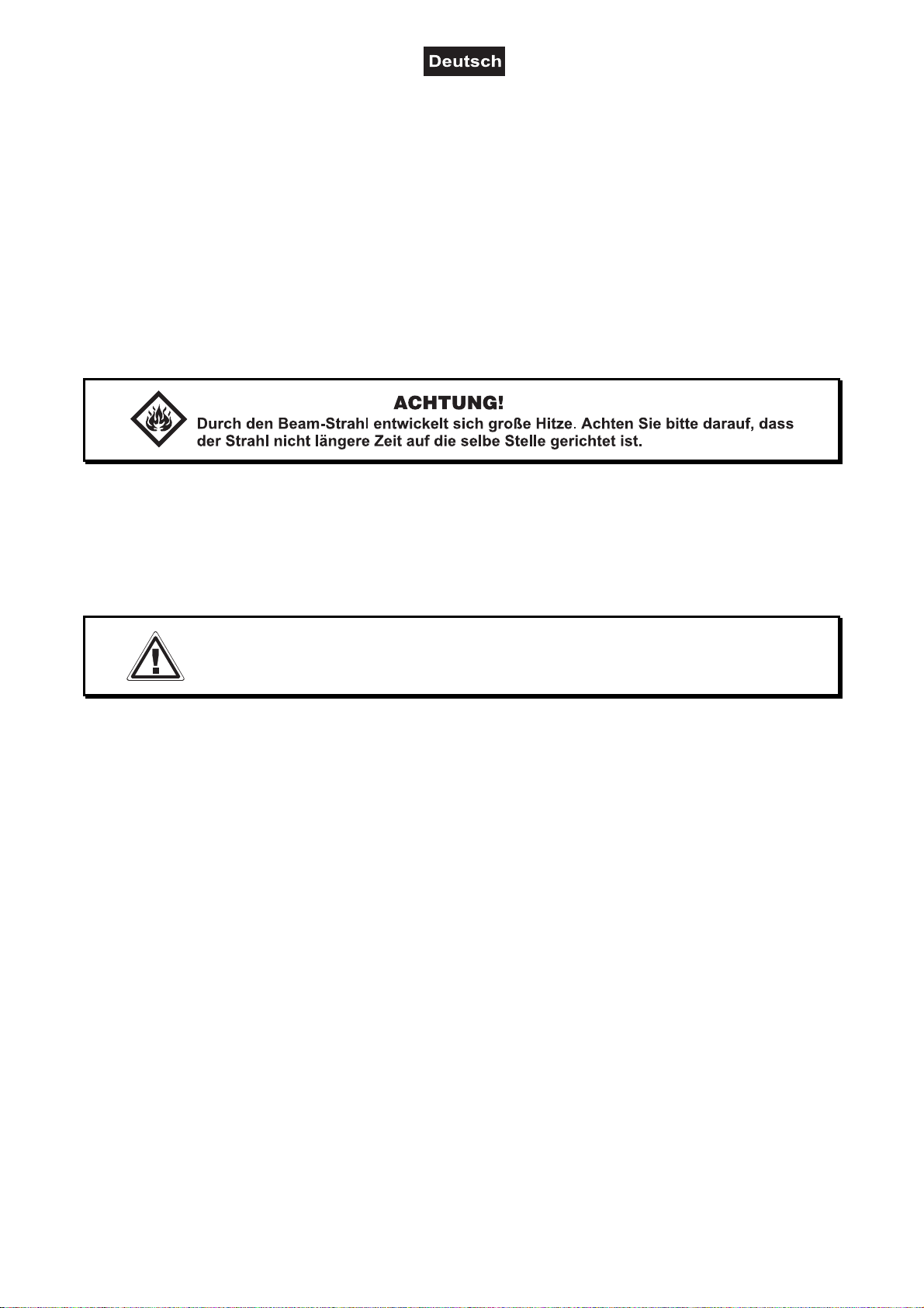
Brandgefahr! Gerät niemals auf leicht entflammbaren Oberflächen aufstellen (z. B. Messeteppich)!
Achtung: Gerät niemals während des Betriebes berühren. Gehäuse erhitzt sich!
Vermeiden Sie es, das Gerät in kurzen Intervallen an- und auszuschalten (z. B. Sekundentakt), da ansonsten die Lebensdauer der Lampe erheblich reduziert werden würde.
GESUNDHEITSRISIKO!
Blicken Sie niemals direkt in die Lichtquelle, da bei empfindlichen Menschen u. U.
epileptische Anfälle ausgelöst werden können (gilt besonders für Epileptiker)!
Kinder und Laien vom Gerät fern halten!
Das Gerät darf niemals unbeaufsichtigt betrieben werden!
BESTIMMUNGSGEMÄSSE VERWENDUNG
Bei diesem Gerät handelt es sich um einen kopfbewegten Scheinwerfer, mit dem sich dekorative Lichteffekte
erzeugen lassen. Dieses Produkt ist für den Anschluss an 100-240 V, 50/60 Hz Wechselspannung
zugelassen und wurde ausschließlich zur Verwendung in Innenräumen konzipiert.
Dieses Gerät ist für professionelle Anwendungen, z. B. auf Bühnen, in Diskotheken, Theatern etc.
vorgesehen.
Lichteffekte sind nicht für den Dauerbetrieb konzipiert. Denken Sie daran, dass konsequente Betriebspausen
die Lebensdauer des Gerätes erhöhen.
Vermeiden Sie Erschütterungen und jegliche Gewaltanwendung bei der Installation oder Inbetriebnahme des
Gerätes.
Das Gerät darf niemals am Projektorkopf angehoben werden, da ansonsten die Mechanik beschädigt
werden könnte. Fassen Sie das Gerät immer an den Tragegriffen an.
Achten Sie bei der Wahl des Installationsortes darauf, dass das Gerät nicht zu großer Hitze, Feuchtigkeit
und Staub ausgesetzt wird. Vergewissern Sie sich, dass keine Kabel frei herumliegen. Bitte achten Sie
darauf, dass das Gerät nicht berührt oder umgestoßen werden kann. Sie gefährden Ihre eigene und die
Sicherheit Dritter!
00092351, Version 1.1 6/72
Page 7
Das Gerät darf nicht in einer Umgebung eingesetzt oder gelagert werden, in der mit Spritzwasser, Regen,
Feuchtigkeit oder Nebel zu rechnen ist. Feuchtigkeit oder sehr hohe Luftfeuchtigkeit kann die Isolation
reduzieren und zu tödlichen Stromschlägen führen. Beim Einsatz von Nebelgeräten ist zu beachten, dass
das Gerät nie direkt dem Nebelstrahl ausgesetzt ist und mindestens 0,5 m von einem Nebelgerät entfernt
betrieben wird. Der Raum darf nur so stark mit Nebel gesättigt sein, dass eine gute Sichtweite von
mindestens 10 m besteht.
Die Umgebungstemperatur muss zwischen -5° C und +45° C liegen. Halten Sie das Gerät von direkter
Sonneneinstrahlung (auch beim Transport in geschlossenen Wägen) und Heizkörpern fern.
Die relative Luftfeuchte darf 50 % bei einer Umgebungstemperatur von 45° C nicht überschreiten.
Dieses Gerät darf nur in einer Höhenlage zwischen -20 und 2000 m über NN betrieben werden.
Verwenden Sie das Gerät nicht bei Gewitter. Überspannung könnte das Gerät zerstören. Das Gerät bei
Gewitter allpolig vom Netz trennen (Netzstecker ziehen).
Das Bildzeichen
---m
bezeichnet den Mindestabstand zu beleuchteten Gegenständen. Der Abstand
zwischen Lichtaustritt und der zu beleuchteten Fläche darf diesen Wert nicht unterschreiten!
Das Gerät darf nur auf nicht brennbaren Oberflächen aufgestellt werden. Um eine gute Luftzirkulation zu
gewährleisten, muss um das Gerät ein Freiraum von mindestens 50 cm eingehalten werden. Bitte beachten
Sie, dass wärmeempfindliche Gegenstände durch die emittierte Wärme verformt oder beschädigt werden
können.
Achten Sie bei der Projektormontage, beim Projektorabbau und bei der Durchführung von Servicearbeiten
darauf, dass der Bereich unterhalb des Montageortes abgesperrt ist.
Bei Überkopfmontage (Montagehöhe >100 cm) ist das Gerät immer mit einem geeigneten Sicherungsseil zu
sichern. Das Sicherungsseil muss an den dafür vorgesehenen Befestigungspunkten eingehängt werden.
Das Sicherungsseil darf niemals an den Transportgriffen eingehängt werden!
Betreiben Sie das Gerät nur, nachdem Sie sich vergewissert haben, dass das Gehäuse fest verschlossen ist
und alle nötigen Schrauben fest angezogen wurden.
Die Lampe darf niemals gezündet werden, wenn die Objektivlinse oder Gehäuseabdeckungen entfernt
wurden, da bei Entladungslampen Explosionsgefahr besteht und eine hohe UV-Strahlung auftritt, die zu
Verbrennungen führen kann.
Die maximale Umgebungstemperatur T
= 45° C darf niemals überschritten werden.
a
Nehmen Sie das Gerät erst in Betrieb, nachdem Sie sich mit seinen Funktionen vertraut gemacht haben.
Lassen Sie das Gerät nicht von Personen bedienen, die sich nicht mit dem Gerät auskennen. Wenn Geräte
nicht mehr korrekt funktionieren, ist das meist das Ergebnis von unfachmännischer Bedienung!
Soll das Gerät transportiert werden, verwenden Sie bitte die Originalverpackung, um Transportschäden zu
vermeiden.
Beachten Sie bitte, dass eigenmächtige Veränderungen an dem Gerät aus Sicherheitsgründen verboten
sind.
Der Serienbarcode darf niemals vom Gerät entfernt werden, da ansonsten der Garantieanspruch erlischt.
Wird das Gerät anders verwendet als in dieser Bedienungsanleitung beschrieben, kann dies zu Schäden am
Produkt führen und der Garantieanspruch erlischt. Außerdem ist jede andere Verwendung mit Gefahren, wie
z. B. Kurzschluss, Brand, elektrischem Schlag, Lampenexplosion, Abstürzen etc. verbunden.
WEEE-Richtlinie
Bitte übergeben Sie das Gerät bzw. die Geräte am Ende der Nutzungsdauer zur umweltgerechten
Entsorgung einem örtlichen Recyclingbetrieb. Nicht im Hausmüll entsorgen. Für weitere Informationen
wenden Sie sich bitte an Ihren Händler oder die zuständige örtliche Behörde.
00092351, Version 1.1 7/72
Page 8

GERÄTEBESCHREIBUNG
Features
Verwandlungskünstler: Spot-, Beam- und Washlight vereint in einem leistungsstarken Moving-Hea d
• Ausgestattet mit einer Osram Sirius HRI 280-W-Entladungslampe
• Optionaler Drahtlos-Empfänger für WDMX-Betrieb (Wireless Solution - made in Sweden) kann
nachgerüstet werden
• Unterstützt RDM (Remote Device Management)
• Hohe PAN-/TILT-Geschwindigkeit
• 14, 16, 20 oder 23 DMX-Kanäle wählbar
• Spot, Beam und durch den Frostfiltereinsatz auch Washlight in einem Gerät
• Farbrad mit 13 unterschiedlichen dichroitischen Farbfiltern und offen
• Rainbow-Effekt mit variabler Geschwindigkeit in beide Richtungen
• Effektrad mit rotierendem 6-Facetten-Prisma (linear) und 8-Facetten-Prisma sowie Frostfilter
• Das Prisma rotiert in beide Richtungen und mit verschiedenen Geschwindigkeiten
• Goborad 1 mit 9 rotierenden Gobos plus offen
• Alle rotierenden Gobos sind austauschbar
• Slot-In-Gobo-System für Gobowechsel ohne Werkzeug
• Goborad 2 mit 14 statischen Gobos plus offen
• Mit Gobo-Shake-Funktion
• Strobe-Effekt mit variabler Geschwindigkeit
• Strobe-Effekt über Zufallsgenerator
• Motorischer Fokus
• Autofokus
• Motorischer Zoom mit 2 - 10° Abstrahlwinkel (Beammodus) und 5,5 - 23°Abstrahlwinkel (Spotmodus)
• Dimmer
• PAN-Winkel zwischen 540° und 630° umschaltbar
• Exakte Positionierung durch 16 Bit Auflösung der PAN/TILT-Bewegung
• Automatische Positionskorrektur
• Schaltnetzteiltechnologie, automatische Anpassung der Netzspannung zwischen 100 und 240 Volt ohne
Umschaltung
• ESDC-Funktion (Easy Service Data Check) mit batteriegepuffertem Control Board zum Auslesen der
Betriebszeiten etc. (Li-Ion Akku 3.7V, AAA, 10440 nicht im Lieferumfang enthalten)
• Control-Board mit grafischem LCD zur Einstellung der DMX-Startadresse, PAN-/TILT-Reverse, Reset,
Lampenschaltung, Betriebsstundenzähler
• DMX-gesteuerter Betrieb oder Standalone-Betrieb mit Master-/Slave-Funktion möglich
• Anzahl der Szenen im Program Run kann beliebig verändert werden
• Die Szenen im Program Run lassen sich über das Control-Board oder externen Controller individuell
anpassen und in den Speicher laden
• Software-Upload über optionales Zubehör via DMX-Verbindung
• Mit Osram Sirius HRI 280 W Lampe
• Netzanschluss über Neutrik PowerCon-Buchse und beiliegendes Netzkabel
• DMX512-Steuerung über jeden handelsüblichen DMX-Controller möglich
00092351, Version 1.1 8/72
Page 9
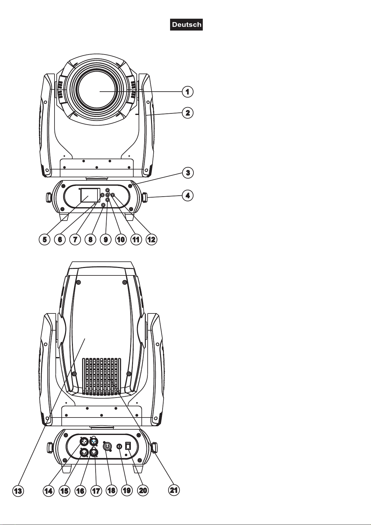
Geräteübersicht
(1) Objektivlinse
(2) Projektorarm
(3) Base
(4) Tragegriff
(5) LCD-Display
(6) Mikrofon
(7) Pfeil-Taste nach links
(8) ESDC-Schalter
(9) Pfeil-Taste nach unten
(10) Enter-Taste
(11) Pfeil-Taste nach oben
(12) Pfeil-Taste nach rechts
(13) Projektorkopf
(14) 3-polige DMX-Eingangsbuchse
(15) 5-polige DMX-Eingangsbuchse
(16) 3-polige DMX-Ausgangsbuchse
(17) 5-polige DMX-Ausgangsbuchse
(18) Spannungsversorgungseingang
(19) Sicherungshalter
(20) Netzschalter
(21) Lüftergitter
00092351, Version 1.1 9/72
Page 10
INSTALLATION
Lampeninstallation/Lampenwechsel
LEBENSGEFAHR!
Lampe nur bei ausgeschaltetem Gerät einsetzen!
Netzstecker ziehen!
Zur Installation benötigen Sie eine Osram Sirius HRI 280 W Entladungslampe.
Die Lampe darf nur nach Anlegen geeigneter Schutzkleidung (Schutzbrille, Schutzhandschuhe, Schutzhelm
mit Visier, Lederschurz) gewechselt werden.
ACHTUNG!
Die Lampe muss gewechselt werden, wenn diese beschädigt ist
oder sich durch Wärme verformt hat!
Die vom Hersteller angegebene Lebensdauer der Lampe darf niemals überschritten werden. Führen Sie
deshalb Buch über die Betriebsstunden der Lampe bzw. kontrollieren Sie den Betriebsstundenzähler in
regelmäßigen Abständen und ersetzen Sie die Lampe rechtzeitig!
Ausgebaute Leuchtmittel in einem splittergeschützten Behälter aufbewahren und fachgerecht entsorgen!
Die verwendete Lampe erreicht Temperaturen von bis zu 600° C.
Vor dem Wechseln der Lampe diese unbedingt erst abkühlen lassen (ca. 10 Minuten) und das Gerät
allpolig von der Netzspannung trennen (Netzstecker ziehen).
Vermeiden Sie es, den Glaskörper mit bloßen Händen zu berühren. Beachten Sie auch unbedingt die Hinweise des Lampenherstellers.
Setzen Sie keine Lampen mit einer höheren Leistungsangabe ein. Lampen mit einer höheren Leistung entwickeln höhere Temperaturen, für die das Gerät nicht ausgelegt ist. Bei Zuwiderhandlungen erlischt die Garantie.
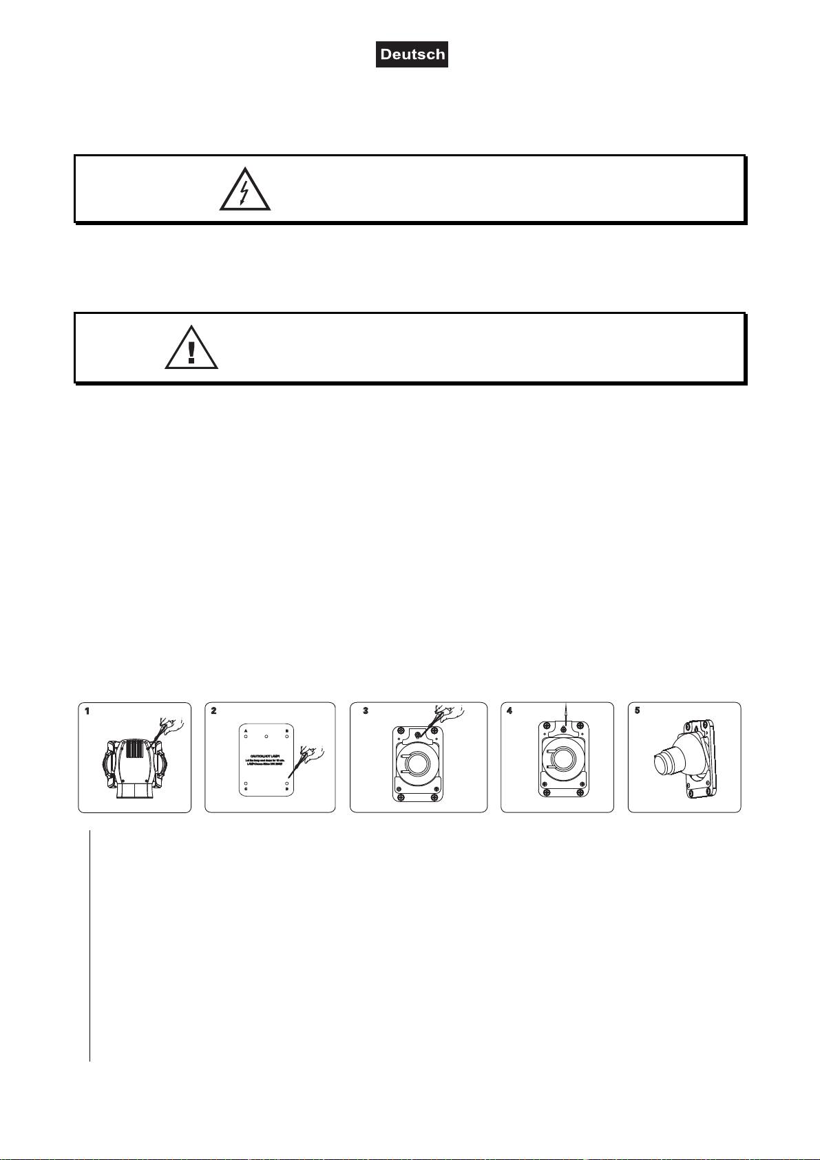
Vorgehensweise:
Schritt 1: Lösen Sie die acht Gehäuseschrauben (Standard-Kreuzschlitz) der Projektorkopfabdeckung
und nehmen Sie die Projektorkopfabdeckung ab.
Schritt 2: Lösen Sie die Befestigungsschrauben A, B, C und D des Lampensystems und nehmen Sie die
Abdeckung vorsichtig vom Gehäuse.
Schritt 3: Schrauben Sie die Befestigungsschraube der Lampenhalterung los.
Schritt 4: Schieben Sie die Platte nach oben.
Schritt 5: Wird eine defekte Lampe ausgetauscht, entfernen Sie zunächst die defekte Lampe aus dem
Lampenhalter. Lösen Sie hierfür zuerst die beiden Anschlussdrähte vorsichtig vom Sockel der
Lampe. Führen Sie die Lampe vorsichtig aus dem Lampenhalter.
Schritt 6: Setzen Sie die neue Lampe vorsichtig wieder ein. Stecken Sie die beiden Anschlussdrähte
vorsichtig auf. Bitte stellen Sie sicher, dass sich die Lampe in der gleichen Position wie die
ausgetauschte Lampe befindet, bevor Sie das Gerät wieder schließen.
Schritt 7: Schließen Sie das Lampensystem wieder und ziehen Sie die Befestigungsschrauben fest.
Schritt 8: Setzen Sie die Projektorabdeckung wieder auf und ziehen Sie die Schrauben fest.
00092351, Version 1.1 10/72
Page 11
Achtung: Bitte beachten Sie, dass die Osram Sirius HRI 280 W Lampe keine heiß-zündfähige Lampe
ist. Bevor Sie die Lampe erneut zünden können, müssen Sie ca. 10 Minuten warten!
Schalten Sie das Gerät niemals ein, ohne vorher alle Abdeckungen geschlossen zu haben!
Einsetzen/Austauschen von Gobos
LEBENSGEFAHR!
Gobos nur bei ausgeschaltetem Gerät austauschen
Netzstecker ziehen!
Wenn Sie andere Formen und Muster als die Standard-Gobos verwenden möchten, oder Gobos
ausgetauscht werden sollen, gehen Sie wie folgt vor:
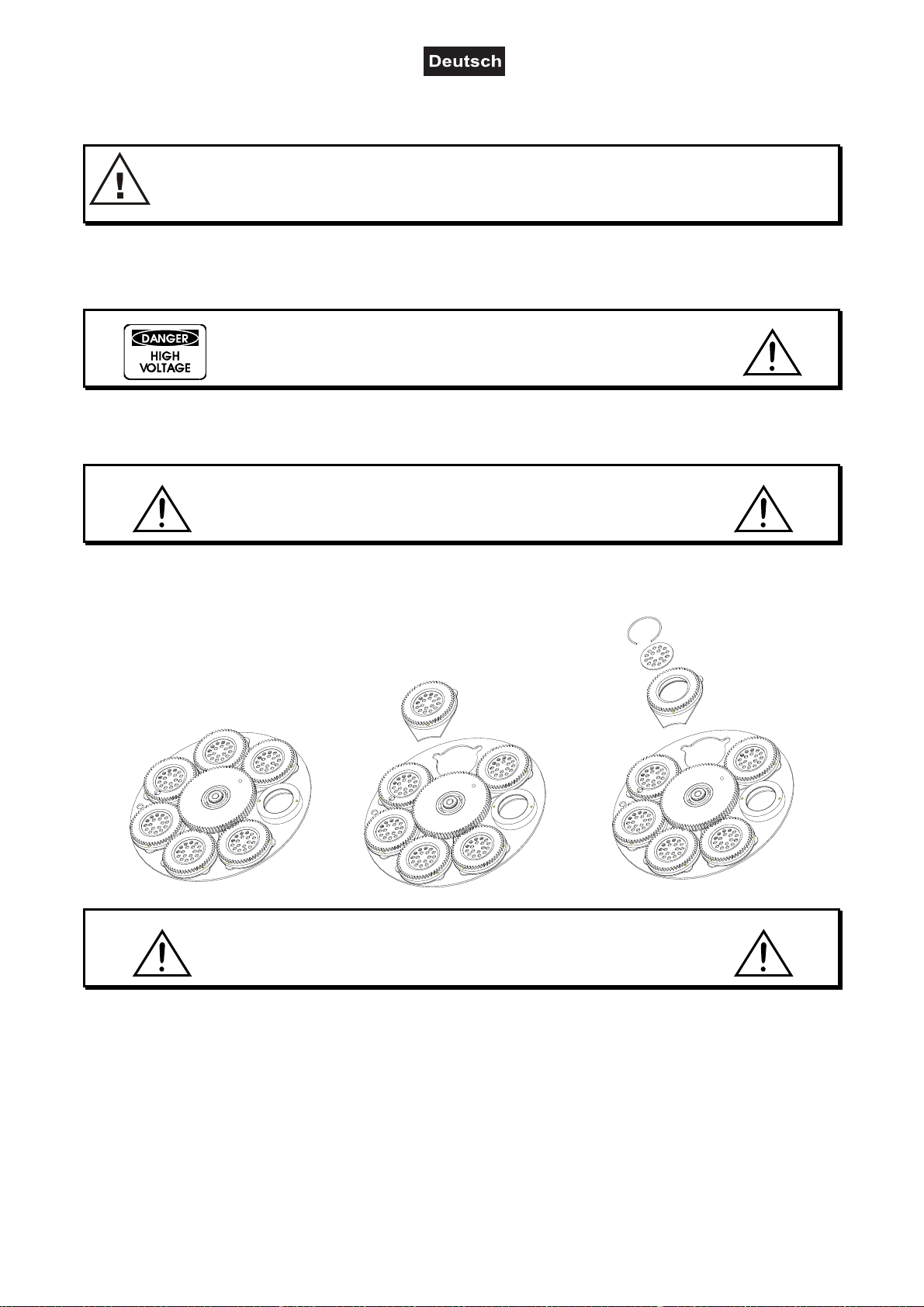
ACHTUNG!
Niemals die Schrauben der rotierenden Gobos lösen,
da ansonsten die Kugellager geöffnet werden!
Entfernen Sie den Sprengring mit einem geeigneten Werkzeug. Entnehmen Sie das Gobo und setzen Sie
das neue Gobo ein. Drücken Sie den Sprengring zusammen und setzen Sie ihn vor das Gobo.
Hinweis!
Slot In Gobo-System für Gobowechsel ohne Werkzeug!
Einsetzen/Austauschen der Gobos wie oben beschrieben.
00092351, Version 1.1 11/72
Page 12
Projektormontage
Die Aufhängevorrichtungen des Projektors muss so gebaut und bemessen sein, dass sie 1 Stunde lang
ohne dauernde schädliche Deformierung das 10-fache der Nutzlast aushalten kann.
Die Installation muss immer mit einer zweiten, unabhängigen Aufhängung, z. B. einem geeigneten Fangnetz,
erfolgen. Diese zweite Aufhängung muss so beschaffen und angebracht sein, dass im Fehlerfall der
Hauptaufhängung kein Teil der Installation herabfallen kann.
Während des Auf-, Um- und Abbaus ist der unnötige Aufenthalt im Bereich von Bewegungsflächen, auf
Beleuchterbrücken, unter hochgelegenen Arbeitsplätzen sowie an sonstigen Gefahrbereichen verboten.
Der Unternehmer hat dafür zu sorgen, dass sicherheitstechnische und maschinentechnische Einrichtungen
vor der ersten Inbetriebnahme und nach wesentlichen Änderungen vor der Wiederinbetriebnahme durch
Sachverständige geprüft werden.
Der Unternehmer hat dafür zu sorgen, dass sicherheitstechnische und maschinentechnische Einrichtungen
mindestens alle vier Jahre durch einen Sachverständigen im Umfang der Abnahmeprüfung geprüft werden.
Der Unternehmer hat dafür zu sorgen, dass sicherheitstechnische und maschinentechnische Einrichtungen
mindestens einmal jährlich durch einen Sachkundigen geprüft werden.
Vorgehensweise:
Der Projektor sollte idealerweise außerhalb des Aufenthaltsbereiches von Personen installiert werden.
WICHTIG! ÜBERKOPFMONTAGE ERFORDERT EIN HOHES MAß AN ERFAHRUNG. Dies beinhaltet (aber
beschränkt sich nicht allein auf) Berechnungen zur Definition der Tragfähigkeit, verwendetes Installationsmaterial und regelmäßige Sicherheitsinspektionen des verwendeten Materials und des Projektors.
Versuchen Sie niemals, die Installation selbst vorzunehmen, wenn Sie nicht über eine solche Qualifikation
verfügen, sondern beauftragen Sie einen professionellen Installateur. Unsachgemäße Installationen können
zu Verletzungen und/oder zur Beschädigung von Eigentum führen.
Der Projektor muss außerhalb des Handbereichs von Personen installiert werden.
Wenn der Projektor von der Decke oder hochliegenden Trägern etc. abgehängt werden soll, muss immer mit
Traversensystemen gearbeitet werden. Der Projektor darf niemals frei schwingend im Raum befestigt
werden.
Achtung: Projektoren können beim Herabstürzen erhebliche Verletzungen verursachen! Wenn Sie Zweifel
an der Sicherheit einer möglichen Installationsform haben, installieren Sie den Projektor NICHT!
Vergewissern Sie sich vor der Montage, dass die Montagefläche mindestens die 10-fache Punktbelastung
des Eigengewichtes des Projektors aushalten kann.
BRANDGEFAHR!
Achten Sie bei der Installation des Gerätes bitte darauf, dass sich im Abstand
von mind. 0,5 m keine leicht entflammbaren Materialien (Deko, etc.) befinden.
00092351, Version 1.1 12/72
Page 13
ACHTUNG!
Montieren Sie den Projektor ausschließlich über zwei geeignete Haken. Bitte
beachten Sie auch die Installationshinweise auf der Unterseite der
Base. Achten Sie darauf, dass das Gerät sicher befestigt wird.
Vergewissern Sie sich, dass die Verankerung stabil ist.
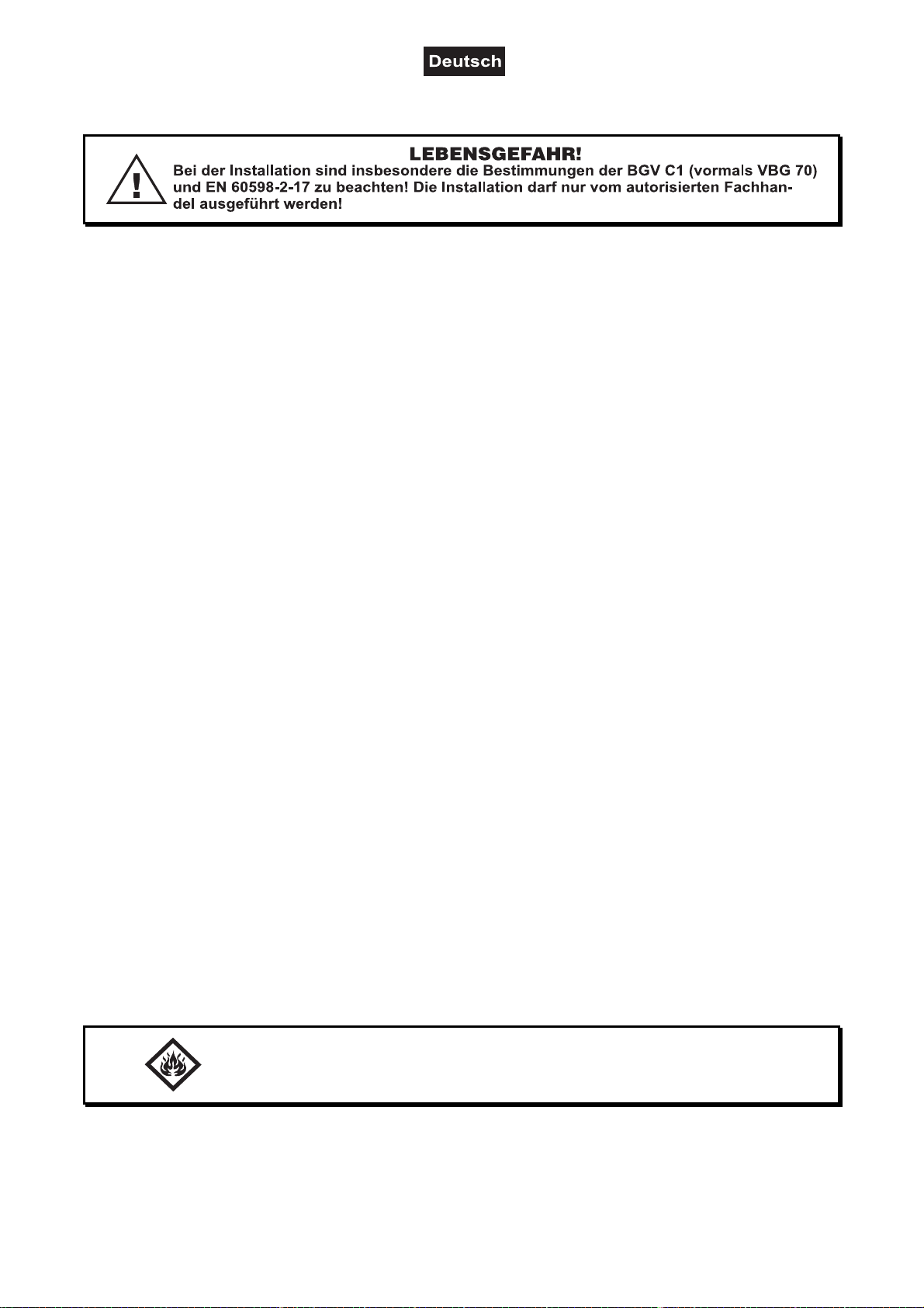
Die Projektorbase lässt sich auf zwei verschiedene Arten montieren.
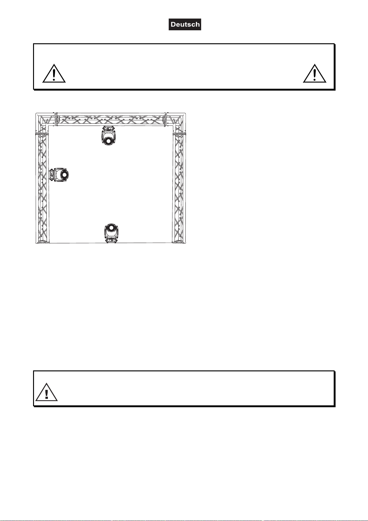
Das Gerät kann direkt auf den Boden gestellt
werden oder in jeder möglichen Position im
Trussing installiert werden, ohne seine
funktionellen Eigenschaften zu verändern.
Sichern Sie den Projektor bei Überkopfmontage
(Montagehöhe >100 cm) immer mit einem
geeignetem Sicherungsseil.
Es dürfen nur Sicherungsseile und
Schnellverbindungsglieder gemäß DIN 56927,
Schäkel gemäß DIN EN 1677-1 und BGV C1
Kettbiner eingesetzt werden. Die Fangseile,
Schnellverbindungsglieder, Schäkel und Kettbiner
müssen auf Grundlage der aktuellsten
Arbeitsschutzbestimmungen (z. B. BGV C1, BGI
810-3) ausreichend dimensioniert sein und korrekt
angewendet werden.
Bitte beachten Sie: Bei Überkopfmontage in öffentlichen bzw. gewerblichen Bereichen ist eine Fülle von
Vorschriften zu beachten, die hier nur auszugsweise wiedergegeben werden können. Der Betreiber muss
sich selbständig um die Beschaffung der geltenden Sicherheitsvorschriften bemühen und diese einhalten!
Der Hersteller haftet nicht für Schäden, die durch unsachgemäße Installation und unzureichende Sicherheitsvorkehrungen verursacht werden!
Hängen Sie das Schnellverschlussglied in die dafür vorgesehene Fangseilöse am Geräteboden ein. Führen
Sie das Sicherungsseil über die Traverse bzw. einen sicheren Befestigungspunkt. Hängen Sie das Ende in
dem Schnellverschlussglied ein und ziehen Sie die Sicherungsmutter gut fest.
Der maximale Fallabstand darf 20 cm nicht überschreiten.
Ein Sicherungsseil, das einmal der Belastung durch Absturz ausgesetzt war oder beschädigt ist, darf nicht
mehr als Sicherungsseil eingesetzt werden.
LEBENSGEFAHR!
Vor der ersten Inbetriebnahme muss die Einrichtung durch einen Sachverständigen geprüft werden!
00092351, Version 1.1 13/72
Page 14
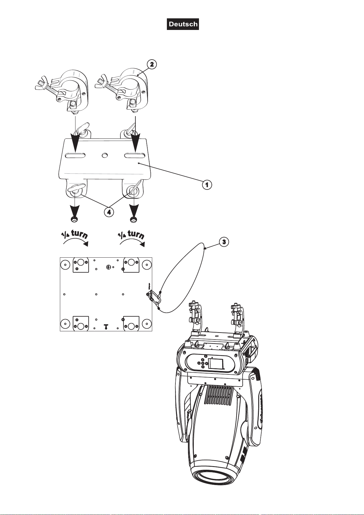
Montage über die Adapterplatte
Verschrauben Sie beide Haken
über eine M10 Schraube und
selbstsichernde Mutter mit den
entsprechenden Löchern der
Adapterplatte.
Die Haken lassen sich horizontal
oder vertikal verschrauben.
Führen Sie die vier
Schnellverschlüsse der
Adapterplatte in die dafür
vorgesehenen Öffnungen an der
Geräteunterseite ein. Drehen Sie
die Schnellverschlüsse im
Uhrzeigersinn bis zum Anschlag
fest.
(1) Adapterplatte
(2) Haken
(3) Sicherheitsfangseil
(4) Schnellverschluss
00092351, Version 1.1 14/72
Page 15
Einbau des optionalen drahtlos-Empfängers für WDMX-Betrieb (FUTURELIGHT
WDR-G4)
ACHTUNG!
Vor Einbau des Moduls das Gerät vom Netz trennen.
Gefahr eines elektrischen Schlages!
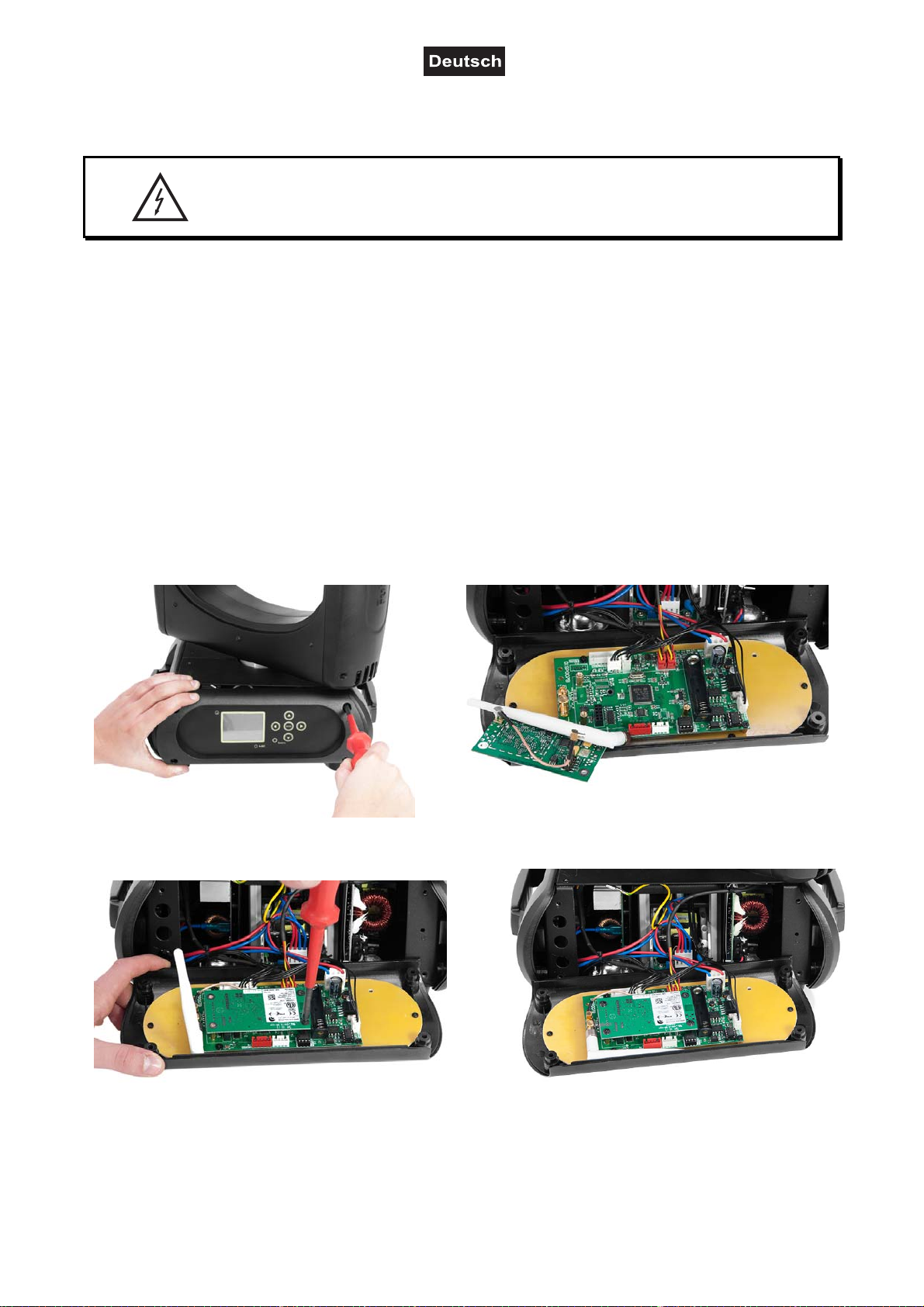
Installationsschritte
1. Nehmen Sie den Drahtlos-DMX-Empfänger aus der Verpackung. Das Modul besteht aus einer
Stabantenne mit Gewinde, der Wireless-Platine und einem Verbindungskabel.
2. Entfernen Sie nun die vier Schrauben des Control-Boards, an der Gerätevorderseite und klappen Sie die
Control-Board-Abdeckung vorsichtig nach vorne. Auf der linken Seite des Display-Boards befinden sich
die beiden Anschlussbuchsen für den Drahtlos-DMX-Empfänger.
3. Schrauben Sie zuerst die Stabantenne auf der Antennenbuchse fest und legen Sie die Antenne entlang
des Display-Boards in die Control-Board-Abdeckung.
4. Zur Befestigung des Wireless-Moduls lösen Sie die drei Schrauben auf den Distanzbolzen und entfernen
Sie sie. Stecken Sie die Steckkontakte des Wireless-Moduls in die Buchse auf dem Display-Board und
schrauben die drei Schrauben wieder fest. Stecken Sie den Antennenstecker des Verbindungskabels in
die dafür vorgesehene Buchse.
5. Klappen Sie die Control-Board-Abdeckung vorsichtig wieder zu und schrauben die vier Schrauben an
der Vorderseite wieder fest.
A B
C D
00092351, Version 1.1 15/72
Page 16

Anschluss an den DMX-512 Controller / Verbindung Projektor – Projektor
Achten Sie darauf, dass die Adern der Datenleitung an keiner
Stelle miteinander in Kontakt treten. Die Geräte werden
ansonsten nicht bzw. nicht korrekt funktionieren.
Beachten Sie, dass die Startadresse abhängig vom verwendeten Controller ist.
Unbedingt Bedienungsanleitung des verwendeten Controllers beachten.
Die Verbindung zwischen Controller und Gerät sowie zwischen den einzelnen Geräten sollte mit einem
DMX-Kabel erfolgen. Die Steckverbindung geht über 3- bzw. 5-polige XLR-Stecker und -Kupplungen.
Belegung der XLR-Verbindung:
Wenn Sie Controller mit dieser XLR-Belegung verwenden, können Sie den DMX-Ausgang des Controllers
direkt mit dem DMX-Eingang des ersten Gerätes der DMX-Kette verbinden. Sollen DMX-Controller mit
anderen XLR-Ausgängen angeschlossen werden, müssen Adapterkabel verwendet werden.
Aufbau einer seriellen DMX-Kette:
Schließen Sie den DMX-Ausgang des ersten Gerätes der Kette an den DMX-Eingang des nächsten Gerätes
an. Verbinden Sie immer einen Ausgang mit dem Eingang des nächsten Gerätes bis alle Geräte angeschlossen sind.
Achtung: Am letzten Gerät muss das DMX-Kabel durch einen Abschlusswiderstand abgeschlossen werden.
Dazu wird ein XLR-Stecker in den DMX-Ausgang am letzten Gerät gesteckt, bei dem zwischen Signal (–)
und Signal (+) ein 120
Widerstand eingelötet ist.
00092351, Version 1.1 16/72
Page 17

Anschluss ans Netz
Schließen Sie das Gerät über die beiliegende Netzanschlussleitung ans Netz an.
Die Belegung der Anschlussleitungen ist wie folgt:
Leitung Pin International
Braun Außenleiter L
Blau Neutralleiter N
Gelb/Grün Schutzleiter
Der Schutzleiter muss unbedingt angeschlossen werden!
Wenn das Gerät direkt an das örtliche Stromnetz angeschlossen wird, muss eine Trennvorrichtung mit
mindestens 3 mm Kontaktöffnung an jedem Pol in die festverlegte elektrische Installation eingebaut werden.
Das Gerät darf nur an eine Elektroinstallation angeschlossen werden, die den VDE-Bestimmungen
DIN VDE 0100 entspricht. Die Hausinstallation muss mit einem Fehlerstromschutzschalter (RCD) mit 30 mA
Bemessungsdifferenzstrom ausgestattet sein.
Lichteffekte dürfen nicht über Dimmerpacks geschaltet werden.
Das Gerät ist mit einer verriegelbaren Netzanschlussbuchse ausgestattet. Schließen Sie das Netzkabel an
und drehen Sie es nach rechts bis es einrastet. Stecken Sie den Netzstecker in eine geerdete
Schutzkontaktsteckdose ein.
BEDIENUNG
Über den Netzschalter lässt sich das Gerät ein- bzw. ausschalten.
Wenn Sie das Gerät an die Spannungsversorgung angeschlossen haben, nimmt der PLB-280 den Betrieb
auf. Während des Reset justieren sich die Motoren aus und das Gerät ist danach betriebsbereit.
Stand Alone-Betrieb
Der PLB-280 lässt sich im Stand Alone-Betrieb ohne Controller einsetzen. Trennen Sie dazu den PLB-280
vom Controller und rufen Sie das vorprogrammierte Programm auf. Bitte beachten Sie weitere Hinweise
unter Control Board.
DMX-gesteuerter Betrieb
Über Ihren DMX-Controller können Sie die einzelnen Geräte individuell ansteuern. Dabei hat jeder DMXKanal eine andere Belegung mit verschiedenen Eigenschaften. Die einzelnen DMX-Kanäle und ihre
Eigenschaften sind unter DMX-Protokoll aufgeführt.
Adressierung des Projektors
Über das Control Board können Sie die DMX-Startadresse definieren. Die Startadresse ist der erste Kanal,
auf den der Projektor auf Signale vom Controller reagiert.
Wenn Sie die Startadresse im 23 Kanal-Modus z. B. auf 24 definieren, belegt der Projektor die Steuerkanäle
24 bis 46.
Bitte vergewissern Sie sich, dass sich die Steuerkanäle nicht mit anderen Geräten überlappen, damit der
PLB-280 korrekt und unabhängig von anderen Geräten in der DMX-Kette funktioniert.
Werden mehrere PLB-280 auf eine Adresse definiert, arbeiten sie synchron.
Drücken Sie die Up/Down-Tasten, um die gewünschte Startadresse einzustellen. Nun können Sie den PLB280 über Ihren Controller ansteuern.
00092351, Version 1.1 17/72
Page 18
Bitte beachten Sie:
Schalten Sie das Gerät ein. Das Gerät prüft, ob DMX-512 Daten empfangen werden oder nicht. Werden
keine Daten empfangen, blinkt das Display.
Die Meldung erscheint:
-wenn kein XLR-Kabel (DMX Signalkabel vom Controller) in die DMX-Eingangsbuchse des Gerätes gesteckt
wurde.
-wenn der Controller ausgeschaltet oder defekt ist.
-das Kabel oder der Stecker defekt ist oder das Signalkabel nicht richtig eingesteckt ist.
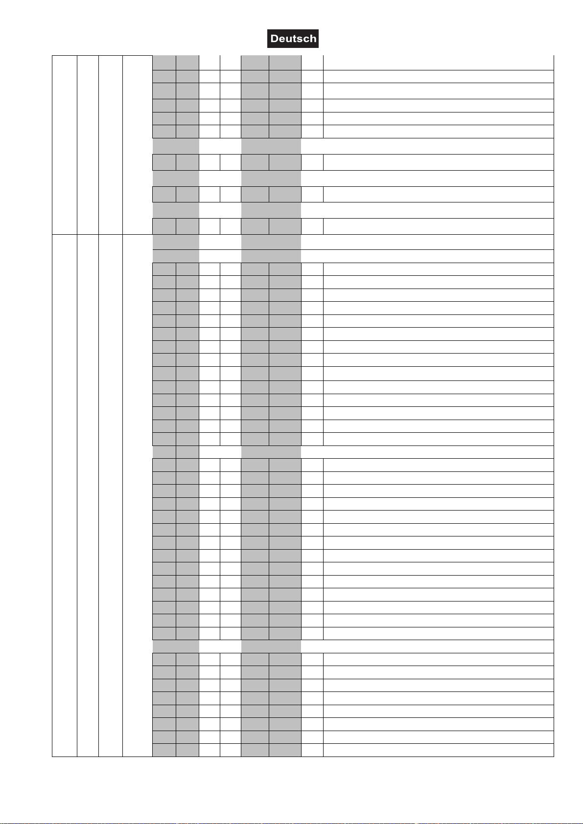
DMX-Protokoll
Mode/Channel Decimal Hexad. Percentage S/F Eigenschaft
Ba-
Ba-
sic
8bit
sic
16bit
0 255 00 FF 0% 100% F
0 255 00 FF 0% 100% F Feinindizierung
0 255 00 FF 0% 100% F
0 255 00 FF 0% 100% F Feinindizierung
0 255 00 FF 0% 100% F
0 15 00 0F 0% 6% S
16 31 10 1F 6% 12% S
32 255 20 FF 13% 100% S
0 15 00 0F 0% 6% S Normale Shutter Funktionen
16 31 10 1F 6% 12% S Öffnender Puls-Effekt
32 47 20 2F 13% 18% S Schließender Puls-Effekt
48 63 30 3F 19% 25% S Strobe-Effekt über Zufallsgenerator
64 255 40 FF 25% 100% S Keine Funktion
Horizontale Bewegung (PAN)
Wenn Sie den Regler verschieben, bewegen Sie
den Kopf horizontal (PAN). Allmähliches Einstellen
des Kopfes bei langsamen Schieben des Reglers
(0-255, 128-Mitte). Der Kopf kann an jeder
gewünschten Einstellung angehalten werden.
PAN-Bewegung mit 16 Bit-Auflösung
Vertikale Bewegung (TILT)
Wenn Sie den Regler verschieben, bewegen Sie
den Kopf vertikal (TILT). Allmähliches Einstellen
des Kopfes bei langsamen Schieben des Reglers
(0-255, 128-Mitte). Der Kopf kann an jeder
gewünschten Einstellung angehalten werden.
TILT-Bewegung mit 16 Bit-Auflösung
Geschwindigkeit PAN-/TILT-Bewegung
Abnehmende Geschwindigkeit
Funktion PAN-/TILT-Bewegung
Normal
Blackout bei PAN-/TILT-Bewegung
Keine Funktion
Funktion Shutter, Strobe
Shutter, Strobe
St. Ex.
1 1 1 1
2 2
2 3 2 3
4 4
3 5 3 5
6
4 7
5 8
0 31 00 1F 0% 12% S Geschlossen
32 223 20 DF 13% 87% F Strobe-Effekt mit zunehmender Geschwindigkeit
224 255 E0 FF 88% 100% S Offen
0 31 00 1F 0% 12% S Geschlossen
32 223 20 DF 13% 87% F Strobe-Effekt mit zunehmender Geschwindigkeit
224 255 E0 FF 88% 100% S Offen
Normale Shutter Funktionen
Öffnender Puls-Effekt
00092351, Version 1.1 18/72
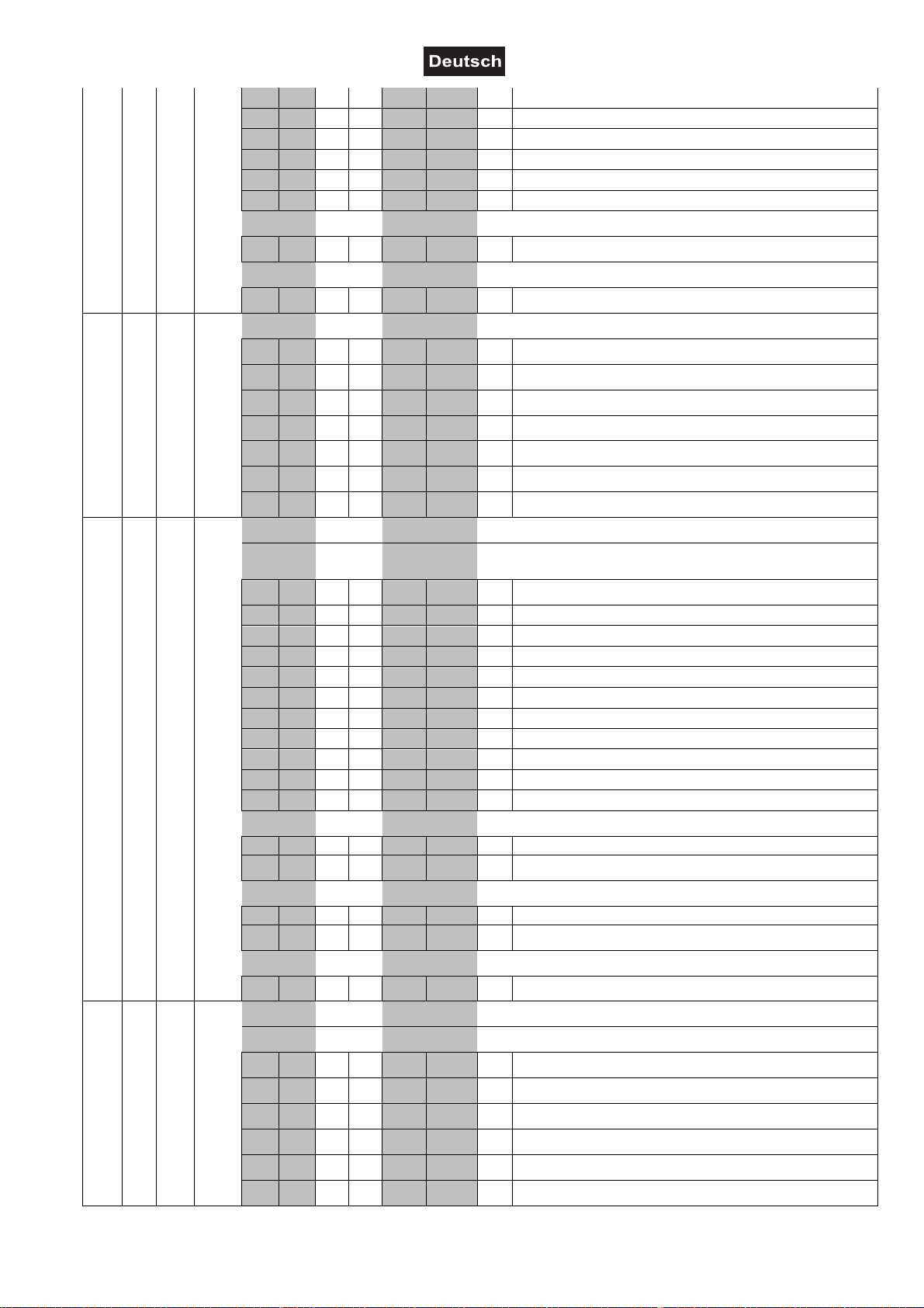
Page 19
4 6
6 9 5 7
7 10
8 11
0 31 00 1F 0% 12% S Geschlossen
32 223 20 DF 13% 87% F Strobe-Effekt mit zunehmender Geschwindigkeit
224 255 E0 FF 88% 100% S Offen
0 31 00 1F 0% 12% S Geschlossen
32 223 20 DF 13% 87% F Strobe-Effekt mit zunehmender Geschwindigkeit
224 255 E0 FF 88% 100% S Offen
0 31 00 1F 0% 12% S Shutter geschlossen
32 63 20 3F 13% 25% S Keine Funktion (Shutter offen)
64 95 40 5F 25% 37% F Strobe-Effekt mit zunehmender Geschwindigkeit
96 127 60 7F 38% 50% S Keine Funktion (Shutter offen)
128 159 80 9F 50% 62% F Puls-Effekt in Sequenzen
160 191 A0 BF 63% 75% S Keine Funktion (Shutter offen)
192 223 C0 DF 75% 87% F
224 255 E0 FF 88% 100% S Keine Funktion (Shutter offen)
0 255 00 FF 0% 100% F
0 15 00 0F 0% 6% S
16 31 10 1F 6% 12% S
32 47 20 2F 13% 18% S
48 63 30 3F 19% 25% S
64 79 40 4F 25% 31% S
80 111 50 6F 31% 44% S
112 255 70 FF 44% 100% S
0 8 00 08 0% 3% S
9 17 09 11 4% 7% S
18 26 12 1A 7% 10% S Position 1
27 35 1B 23 11% 14% S
36 44 24 2C 14% 17% S Position 2
45 53 2D 35 18% 21% S
54 62 36 3E 21% 24% S Position 3
63 71 3F 47 25% 28% S
72 80 48 50 28% 31% S Position 4
81 89 51 59 32% 35% S
90 98 5A 62 35% 38% S Position 5
99 107 63 6B 39% 42% S
108 116 6C 74 42% 45% S Position 6
117 125 75 7D 46% 49% S
126 134 7E 86 49% 53% S Position 7
135 143 87 8F 53% 56% S
144 152 90 98 56% 60% S Position 8
153 161 99 A1 60% 63% S
162 170 A2 AA 64% 67% S Position 9
171 179 AB B3 67% 70% S
180 188 B4 BC 71% 74% S Position 10
189 197 BD C5 74% 77% S
Schließender Puls-Effekt
Strobe-Effekt über Zufallsgenerator
Shutter, Strobe
Strobe-Effekt über Zufallsgenerator mit
zunehmender Geschwindigkeit
Dimmerintensität
Allmähliche Einstellung der Dimmerintensität von 0
bis 100 %
Funktion Farben
Normaler Farbwechsel
Blackout bei Farbwechsel
Rainboweffekt vorwärts
Rainboweffekt rückwärts
Farbwechsel an jeder Position
Schneller Farbsprung
Keine Funktion
Farbrad
Normaler Farbwechsel / Blackout bei Farbwechsel /
schneller Farbsprung
Offen
Offen/Position 1
Position 1/Position 2
Position 2/Position 3
Position 3/Position 4
Position 4/Position 5
Position 5/Position 6
Position 6/Position 7
Position 7/Position 8
Position 8/Position 9
Position 9/Position 10
Position 10/Position 11
00092351, Version 1.1 19/72
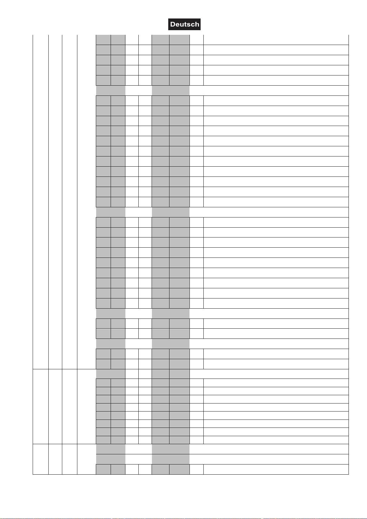
Page 20
6 8
198 206 C6 CE 78% 81% S Position 11
207 215 CF D7 81% 84% S
216 224 D8 E0 85% 88% S Position 12
225 233 E1 E9 88% 91% S
234 242 EA F2 92% 95% S Position 13
243 255 F3 FF 95% 100% S
0 255 00 FF 0% 100% F
0 255 00 FF 0% 100% F
0 255 00 FF 0% 100% F
0 1 00 01 0% 0% S
2 3 02 03 1% 1% S
4 5 04 05 2% 2% S
6 7 06 07 2% 3% S
8 9 08 09 3% 4% S
10 11 0A 0B 4% 4% S
12 13 0C 0D 5% 5% S
14 15 0E 0F 5% 6% S
16 17 10 11 6% 7% S
18 19 12 13 7% 7% S
20 21 14 15 8% 8% S
22 23 16 17 9% 9% S
24 25 18 19 9% 10% S
26 27 1A 1B 10% 11% S
28 29 1C 1D 11% 11% S
30 31 1E 1F 12% 12% S
32 33 20 21 13% 13% S
34 35 22 23 13% 14% S
36 37 24 25 14% 15% S
38 39 26 27 15% 15% S
40 41 28 29 16% 16% S
42 43 2A 2B 16% 17% S
44 45 2C 2D 17% 18% S
46 47 2E 2F 18% 18% S
48 49 30 31 19% 19% S
50 51 32 33 20% 20% S
52 53 34 35 20% 21% S
54 55 36 37 21% 22% S
56 67 38 43 22% 26% F
68 79 44 4F 27% 31% F
80 91 50 5B 31% 36% F
92 103 5C 67 36% 40% F
104 115 68 73 41% 45% F
116 127 74 7F 45% 50% F
128 139 80 8B 50% 55% F
140 151 8C 97 55% 59% F
Position 11/Position 12
Position 12/Position 13
Position 13/Offen
Rainboweffekt vorwärts
Mit zunehmender Geschwindigkeit
Rainboweffekt rückwärts
Mit zunehmender Geschwindigkeit
Farbwechsel an jeder Position
Positionierung von 0 - 360 Grad
Farbrad
Normaler Farbwechsel
Offen
Position 1
Position 2
Position 3
Position 4
Position 5
Position 6
Position 7
Position 8
Position 9
Position 10
Position 11
Position 12
Position 13
Blackout bei Farbwechsel
Offen
Position 1
Position 2
Position 3
Position 4
Position 5
Position 6
Position 7
Position 8
Position 9
Position 10
Position 11
Position 12
Position 13
Schneller Farbsprung
Offen
Position 1
Position 2
Position 3
Position 4
Position 5
Position 6
Position 7
00092351, Version 1.1 20/72
Page 21
9 12
10 13
7 9
152 163 98 A3 60% 64% F
164 175 A4 AF 64% 69% F
176 187 B0 BB 69% 73% F
188 199 BC C7 74% 78% F
200 211 C8 D3 78% 83% F
212 223 D4 DF 83% 87% F
224 239 E0 EF 88% 94% F
240 255 F0 FF 94% 100% F
0 15 00 0F 0% 6% S
16 31 10 1F 6% 12% S
32 47 20 2F 13% 18% S
48 63 30 3F 19% 25% S
64 79 40 4F 25% 31% S
80 95 50 5F 31% 37% S
96 255 60 FF 38% 100% S
0 3 00 03 0% 1% S/F
4 25 04 19 2% 10% S/F
26 47 1A 2F 10% 18% S/F
48 69 30 45 19% 27% S/F
70 91 46 5B 27% 36% S/F
92 113 5C 71 36% 44% S/F
114 135 72 87 45% 53% S/F
136 157 88 9D 53% 62% S/F
158 179 9E B3 62% 70% S/F
180 201 B4 C9 71% 79% S/F
202 255 CA FF 79% 100% S/F
0 7 00 07 0% 3% S Stopp
8 255 08 FF 3% 100% F
0 7 00 07 0% 3% S Stopp
8 255 08 FF 3% 100% F
0 255 00 FF 0% 100% F
0 1 00 01 0% 0% S
2 4 02 04 1% 2% S
5 7 05 07 2% 3% S
8 10 08 0A 3% 4% S
11 13 0B 0D 4% 5% S
14 16 0E 10 5% 6% S
Position 8
Position 9
Position 10
Position 11
Position 12
Position 13
Rainboweffekt vorwärts
Mit zunehmender Geschwindigkeit
Rainboweffekt rückwärts
Mit zunehmender Geschwindigkeit
Funktion rotierendes Goborad, Gobo-Shake
Normaler Gobowechsel
Blackout bei Gobowechsel
Rotierendes Goborad vorwärts
Rotierendes Goborad rückwärts
Gobowechsel an jeder Position
Gobo-Shake
Keine Funktion
Rotierendes Goborad, Gobo-Shake
Normaler Gobowechsel / Blackout bei
Gobowechsel / Gobo-Shake
Beam offen
Spot offen
Position 1
Position 2
Position 3
Position 4
Position 5
Position 6
Position 7
Position 8
Position 9
Rotierendes Goborad vorwärts
Mit zunehmender Geschwindigkeit
Rotierendes Goborad rückwärts
Mit zunehmender Geschwindigkeit
Gobowechsel an jeder Position
Positionierung von 0 - 360 Grad
Rotierendes Goborad, Gobo-Shake
Normaler Gobowechsel
Beam offen
Spot offen
Position 1
Position 2
Position 3
Position 4
00092351, Version 1.1 21/72
Page 22
11 14
12 15
17 19 11 13 7% 7% S
20 22 14 16 8% 9% S
23 25 17 19 9% 10% S
26 28 1A 1C 10% 11% S
29 48 1D 30 11% 19% S
49 50 31 32 19% 20% S
51 53 33 35 20% 21% S
54 56 36 38 21% 22% S
57 59 39 3B 22% 23% S
60 62 3C 3E 24% 24% S
63 65 3F 41 25% 25% S
66 68 42 44 26% 27% S
69 71 45 47 27% 28% S
72 74 48 4A 28% 29% S
75 77 4B 4D 29% 30% S
78 97 4E 61 31% 38% S
98 111 62 6F 38% 44% F
112 125 70 7D 44% 49% F
126 139 7E 8B 49% 55% F
140 153 8C 99 55% 60% F
154 167 9A A7 60% 65% F
168 181 A8 B5 66% 71% F
182 195 B6 C3 71% 76% F
196 209 C4 D1 77% 82% F
210 223 D2 DF 82% 87% F
224 224 E0 E0 88% 88% S
225 239 E1 EF 88% 94% F
240 240 F0 F0 94% 94% S
241 255 F1 FF 95% 100% F
0 15 00 0F 0% 6% S
16 31 10 1F 6% 12% S
32 47 20 2F 13% 18% S
48 63 30 3F 19% 25% S
64 79 40 4F 25% 31% S
80 95 50 5F 31% 37% S
96 111 60 6F 38% 44% S
112 255 70 FF 44% 100%
0 255 00 FF 0% 100% F
S Keine Funktion
Position 5
Position 6
Position 7
Position 8
Position 9
Blackout bei Gobowechsel
Beam offen
Spot offen
Position 1
Position 2
Position 3
Position 4
Position 5
Position 6
Position 7
Position 8
Position 9
Gobo-Shake
Position 1
Position 2
Position 3
Position 4
Position 5
Position 6
Position 7
Position 8
Position 9
Rotierendes Goborad vorwärts
Stopp
Mit zunehmender Geschwindigkeit
Rotierendes Goborad rückwärts
Stopp
Mit zunehmender Geschwindigkeit
Rotierendes Goborad, Gobo-Rotation
Goboindizierung
Rotierendes Goborad vorwärts
Rotierendes Goborad rückwärts
Bewegungsmakro vorwärts
Bewegungsmakro vorwärts mit Blackout
Bewegungsmakro rückwärts
Bewegungsmakro rückwärts mit Blackout
Rotierendes Goborad, Gobo-Geschwindigkeit
Goboindizierung
Positionierung von 0 - 360 Grad
00092351, Version 1.1 22/72
Page 23

8 10
13 16
14 17
0 7 00 07 0% 3% S
8 255 08 FF 3% 100% F
0 7 00 07 0% 3% S
8 255 08 FF 3% 100% F
0 255 00 FF 0% 100% F
0 255 00 FF 0% 100% F
0 191 00 BF 0% 75% F
192 207 C0 CF 75% 81% F
208 223 D0 DF 82% 87% F
224 224 E0 E0 88% 88% S
225 239 E1 EF 88% 94% F
240 240 F0 F0 94% 94% S
241 255 F1 FF 95% 100% F
0 15 00 0F 0% 6% S
16 31 10 1F 6% 12% S
32 47 20 2F 13% 18% S
48 63 30 3F 19% 25% S
64 79 40 4F 25% 31% S
80 95 50 5F 31% 37% S
96 255 60 FF 38% 100% S
0 16 00 10 0% 6% S/F
17 33 11 21 7% 13% S/F
34 50 22 32 13% 20% S/F
51 67 33 43 20% 26% S/F
68 84 44 54 27% 33% S/F
85 101 55 65 33% 40% S/F
102 118 66 76 40% 46% S/F
119 135 77 87 47% 53% S/F
136 152 88 98 53% 60% S/F
153 169 99 A9 60% 66% S/F
170 186 AA BA 67% 73% S/F
187 203 BB CB 73% 80% S/F
204 220 CC DC 80% 86% S/F
221 237 DD ED 87% 93% S/F
238 255 EE FF 93% 100% S/F
Rotierendes Goborad vorwärts
Stopp
Mit zunehmender Geschwindigkeit
Rotierendes Goborad rückwärts
Stopp
Mit zunehmender Geschwindigkeit
Bewegungsmakro vorwärts & Bewegungsmakro
vorwärts mit Blackout
Mit zunehmender Geschwindigkeit
Bewegungsmakro rückwärts & Bewegungsmakro
rückwärts mit Blackout
Mit zunehmender Geschwindigkeit
Rotierendes Goborad, Gobo-Geschwindigkeit
Goboindizierung
Positionierung von 0 - 360 Grad
Bewegungsmakro vorwärts
Mit zunehmender Geschwindigkeit
Bewegungsmakro rückwärts
Mit zunehmender Geschwindigkeit
Goborotation vorwärts
Stopp
Mit zunehmender Geschwindigkeit
Goborotation rückwärts
Stopp
Mit zunehmender Geschwindigkeit
Funktion statisches Goborad, Gobo-Shake
Normaler Gobowechsel
Blackout bei Gobowechsel
Rotierendes Goborad vorwärts
Rotierendes Goborad rückwärts
Gobowechsel an jeder Position
Gobo-Shake
Keine Funktion
Statisches Goborad, Gobo-Shake
Normaler Gobowechsel / Blackout bei
Gobowechsel / Gobo-Shake
Offen
Position 1
Position 2
Position 3
Position 4
Position 5
Position 6
Position 7
Position 8
Position 9
Position 10
Position 11
Position 12
Position 13
Position 14
00092351, Version 1.1 23/72
Page 24

9 11
0 7 00 07 0% 3% S
8 255 08 FF 3% 100% F
0 7 00 07 0% 3% S
8 255 08 FF 3% 100% F
0 255 00 FF 0% 100% F
0 2 00 02 0% 1% S
3 5 03 05 1% 2% S
6 8 06 08 2% 3% S
9 11 09 0B 4% 4% S
12 14 0C 0E 5% 5% S
15 17 0F 11 6% 7% S
18 20 12 14 7% 8% S
21 23 15 17 8% 9% S
24 26 18 1A 9% 10% S
27 29 1B 1D 11% 11% S
30 32 1E 20 12% 13% S
33 35 21 23 13% 14% S
36 38 24 26 14% 15% S
39 41 27 29 15% 16% S
42 48 2A 30 16% 19% S
49 51 31 33 19% 20% S
52 54 34 36 20% 21% S
55 57 37 39 22% 22% S
58 60 3A 3C 23% 24% S
61 63 3D 3F 24% 25% S
64 66 40 42 25% 26% S
67 69 43 45 26% 27% S
70 72 46 48 27% 28% S
73 75 49 4B 29% 29% S
76 78 4C 4E 30% 31% S
79 81 4F 51 31% 32% S
82 84 52 54 32% 33% S
85 87 55 57 33% 34% S
88 90 58 5A 35% 35% S
91 97 5B 61 36% 38% S
98 107 62 6B 38% 42% F
108 117 6C 75 42% 46% F
Rotierendes Goborad vorwärts
Stopp
Mit zunehmender Geschwindigkeit
Rotierendes Goborad rückwärts
Stopp
Mit zunehmender Geschwindigkeit
Gobowechsel an jeder Position
Positionierung von 0 - 360 Grad
Statisches Goborad, Gobo-Shake
Normaler Gobowechsel
Offen
Position 1
Position 2
Position 3
Position 4
Position 5
Position 6
Position 7
Position 8
Position 9
Position 10
Position 11
Position 12
Position 13
Position 14
Blackout bei Gobowechsel
Offen
Position 1
Position 2
Position 3
Position 4
Position 5
Position 6
Position 7
Position 8
Position 9
Position 10
Position 11
Position 12
Position 13
Position 14
Gobo-Shake
Position 2
Position 3
00092351, Version 1.1 24/72
Page 25

15 18 10 12
16 19 11 13
17 20
18 21 12 14
19 22 13 15
118 127 76 7F 46% 50% F
128 137 80 89 50% 54% F
138 147 8A 93 54% 58% F
148 157 94 9D 58% 62% F
158 167 9E A7 62% 65% F
168 177 A8 B1 66% 69% F
178 187 B2 BB 70% 73% F
188 197 BC C5 74% 77% F
198 207 C6 CF 78% 81% F
208 217 D0 D9 82% 85% F
218 223 DA DF 85% 87% F
224 224 E0 E0 88% 88% S
225 239 E1 EF 88% 94% F
240 240 F0 F0 94% 94% S
241 255 F1 FF 95% 100% F
0 63 00 3F 0% 25% S
64 127 40 7F 25% 50% S
128 191 80 BF 50% 75% S
192 255 C0 FF 75% 100% S
0 191 00 BF 0% 75% F
192 223 C0 DF 75% 87% F
224 255 E0 FF 88% 100% F
0 15 00 0F 0% 6% F
16 31 10 1F 6% 12% S
32 47 20 2F 13% 18% S
48 63 30 3F 19% 25% S
64 95 40 5F 25% 37% S
96 127 60 7F 38% 50% S
128 255 80 FF 50% 100% S
0 255 00 FF 0% 100% F
0 255 00 FF 0% 100% F
0 255 00 FF 0% 100% F
Position 4
Position 5
Position 6
Position 7
Position 8
Position 9
Position 10
Position 11
Position 12
Position 13
Position 14
Rotierendes Goborad vorwärts
Stopp
Mit zunehmender Geschwindigkeit
Rotierendes Goborad rückwärts
Stopp
Mit zunehmender Geschwindigkeit
Prisma
Offen
6-Facetten-Prisma (linear)
8-Facetten-Prisma
Frost
Prismenrotation
Prismenwechsel an jeder Position
Positionierung von 0 - 360 Grad
Rotierendes Prisma vorwärts
Mit zunehmender Geschwindigkeit
Rotierendes Prisma rückwärts
Mit zunehmender Geschwindigkeit
Funktion Fokus
Allmähliche Einstellung von nah bis weit
5 m Autofokus (Fokussieren auf Gobos)
7,5 m Autofokus (Fokussieren auf Gobos)
10 m Autofokus (Fokussieren auf Gobos)
15 m Autofokus (Fokussieren auf Gobos)
> 20 m Autofokus (Fokussieren auf Gobos)
Keine Funktion
Fokus
Allmähliche Einstellung von nah bis weit
Nah bis weit
Autofokus
Feinfokussierung nah bis weit
Zoom
Allmähliche Einstellung von nah bis weit
Allmähliche Einstellung von 2 - 10° oder 5,5 - 23°
00092351, Version 1.1 25/72
Page 26

20 23 14 16
0 255 00 FF 0% 100% F
0 7 00 07 0% 3%
8 15 08 0F 3% 6%
16 23 10 17 6% 9%
24 31 18 1F 9% 12%
32 39 20 27 13% 15%
40 47 28 2F 16% 18%
48 55 30 37 19% 22%
56 63 38 3F 22% 25%
64 71 40 47 25% 28%
72 79 48 4F 28% 31%
80 87 50 57 31% 34%
88 95 58 5F 35% 37%
96 255 60 FF 38% 100%
Autofokus
Allmähliche Feineinstellung v. 2 - 10° oder 5,5 - 23°
Reset, Displaysteuerung
S Keine Funktion
S Reset Alle
S Reset PAN/TILT
S Reset Farben
S Reset Gobos
S Keine Funktion
S Reset Übrige
S Display aus
S Display an
S Lampe aus
S Lampe an
S Standby-Modus
S Keine Funktion
00092351, Version 1.1 26/72
Page 27

Control Board
Das Control Board bietet mehrere Möglichkeiten: so lassen sich z. B. die DMX-Startadresse eingeben, das
vorprogrammierte Programm abspielen oder ein Reset durchführen.
Drücken Sie die Enter-Taste, so dass sich das Display einschaltet. Durch Drücken der geeigneten PfeilTaste (nach unten, nach oben, nach links und nach rechts) können Sie sich im Hauptmenü bewegen. Zur
Auswahl des gewünschten Menüpunktes drücken Sie die Enter-Taste. Durch Drücken der geeigneten PfeilTaste können Sie die Auswahl verändern. Bestätigen Sie jede Änderung durch Drücken der Enter-Taste. Die
jeweiligen Funktionen werden im Folgenden beschrieben.
Vorgabewerte grau unterlegt Basic Reload / Program Reload / Private Reload
Hauptmenü Untermenü Display Funktion
Connect
Light
Information
Set
DMX Address
Wireless
Turn on/off
Automatic
DMX Control
Max Temperature
Lamp Adjust
ON/OFF
ON/OFF
ON/OFF
80-139°C,120°C/176-
282°F,248°F
PAN ... Service-Funktion
Current XXXX (h)
Time info
Fixture Life XXXX (h) Betriebsstunden Gerät
Einstellen der DMXStartadresse
Wireless DMX aktivieren
(Sonderausstattung optional)
Lampenschaltung
Lampenschaltung/
Inbetriebnahme
Lampenschaltung über
DMX
Lampe aus bei
Temperaturerreichung
Betriebsstunden Gerät
seit Einschalten
Lamp Life XXXX (h) Betriebsstunden Lampe
Voltage
Lamp info
Current
HID Lampeninformation
Power
Temperature
Near Lamp Temp.
...
XXX °C/°F Innentemperatur
Fans Speed Near Lamp Fan Lüftergeschwindigkeit
Channel Value
PAN ... PAN = XXX ... Startpositionen
Error Message PAN, TILT ... Kanalfehler
Fixture Model Xxxxxxxxxxxxx Gerätemodell und Marke
Software Ver
1U01 V 1.0.00
2U01 V 1.0.00 ...
All
Reset Alle
Software Version jedes
ICs
PAN&TILT Reset PAN/TILT
Reset
Colors Reset Farben
Gobos Reset Gobos
Shutter Reset Shutter
Others Reset Übrige
PAN reverse
TILT reverse ON/OFF
ON/OFF
PAN/TILT-Umkehr
PAN-Winkel zwischen
PAN degree 630/540
630° und 540°
umschaltbar
Movement
Encoders ON/OFF
Automatic PAN/TILT
calibration
PAN/TILT
PAN/TILT Mode Stand/Smooth
Geschwindigkeit
einstellen
00092351, Version 1.1 27/72
Page 28

UI Set
Users
Calibration
Fixture ID
Wireless Set
Reload Default
Mic Sens
No Signal
Temperature C/F Celsius/Fahrenheit
Fans Mode Auto Speed/High Speed
Hibernation OFF, 01M-99M, 15M
Backlight 02M-60M, 02M Display-Abschaltung
Flip Display ON/OFF
Display Bright 00-31 10 Display-Helligkeit
Brand Show ON/OFF Markennamen anzeigen
Key Lock ON/OFF Tastensperre aktivieren
Language En/简/繁/Fr/Sp Sprachauswahl
0~99%, 60%
Close/Hold/Auto/Music
Mikrofonempfindlichkeit
Auto-Modus wenn kein
DMX
Temperatureinheit zw. °C
und °F umschalten
Lüfter Betriebsart einst.
Standby-Modus
Display-Umkehrung um
180°
Standard
User Mode
Extended
Basic-8bit
Basic-16bit
Benutzerdefinierte
Kanalreihenfolge
User
Edit User
--Password--
Color ...
Name
--Password--
PID Code
DMX on cable
Reset Connect
Basic Reload
Program Reload
--Password--
Private Reload
All Reload
Max Channel = XX
PAN = CH01 ...
Password=XXX
Color =XXX ...
ON/OFF
ON/OFF
ON/OFF
ON/OFF
XXX
ON/OFF
ON/OFF
Preset-Benutzerd.
Effektradjustierung;
Standardposition
Passwort „050“
Name
Passwort „050“
PID-Code für RDM
einstellen
Durchschleifen von Daten
Empfänger ausloggen
(Sonderausstattung optional)
Basis Reload
Programm Reload
Password: 050
Privater Reload
Reload Alles
DMX receive Zurück zum DMX-Mode
Slave receive Slave 1, Slave 2, Slave 3 Slave-Einstellung
Play
Select Chase
Program
Edit Chase
Edit Scenes
Scenes Record ScXX=>ScXX
Sequence Master/Alone Autom. Programm Run
Music Master/Alone
Chase Part 1
Chase Part 2
Chase Part 3
Chase 1
:
Chase 8
Edit scene 001
:
Edit scene 250
Chase 1- 8 Chase 1
Chase 1- 8 Chase 2
Chase 1- 8 Chase 3
Chase Test
Step 01 = SCXXX
Step 64 = SCXXX
Pan,Tilt, ...
-- Fade Time --
-- Scene Time -DMX Input
Musikgesteuerter
Programm Run
Programmwahl für Auto
Programm
Testprogramm
Programm Auto Run
Speichern + los
Speichern + zurück
Szenen manuell editieren
Automatische
Szenenaufzeichnung
00092351, Version 1.1 28/72
Page 29

Connect
Einstellen der DMX-Startadresse
Mit dieser Funktion können Sie die DMX-Startadresse über das Control Board einstellen.
• Wählen Sie “DMX Address” durch Drücken der Up/Down-Tasten.
• Drücken Sie die Enter-Taste und stellen Sie die DMX-Adresse durch Drücken der Up/Down-Tasten ein.
• Drücken Sie die Enter-Taste zur Bestätigung.
Wireless
Ein optional erhältlicher Drahtlos-Empfänger für WDMX-Betrieb (Wireless Solution - made in Sweden) kann
nachgerüstet werden.
Mit der Funktion „Wireless“ können Sie den Drahtlos-Empfänger am Drahtlos-Sender einloggen, das Gerät
kann nun drahtlose Signale empfangen.
• Wählen Sie “Wireless” durch Drücken der Up/Down-Tasten.
• Drücken Sie die Enter-Taste zur Bestätigung.
Ist ein Gerät mit eingebautem Drahtlos-Empfänger über ein Kabel mit einem DMX-Controller verbunden,
wird es von dem kabelgebundenen Controller angesteuert und nicht vom Drahtlos-Sender.
Light
Lampenschaltung
Mit dieser Funktion lässt sich die Lampe über das Control Board an- oder abschalten.
• Wählen Sie "Turn on/off" durch Drücken der Up/Down-Tasten.
• Drücken Sie die Enter-Taste, auf dem Display erscheint “ON” oder “OFF”.
• Drücken Sie die Up/Down-Taste zur Auswahl von “ON” um die Lampe anzuschalten, oder “OFF” um sie
abzuschalten.
• Drücken Sie die Enter-Taste zur Bestätigung.
Lampenschaltung bei Inbetriebnahme
Mit dieser Funktion kann das Gerät so programmiert werden, dass die Lampe automatisch zündet, sobald
das Gerät in Betrieb genommen wird. Wählen Sie über die Up/Down-Tasten “ON” wenn Sie diese Funktion
aktivieren möchten – oder “OFF” wenn nicht.
Lampenschaltung über DMX
Mit dieser Funktion kann das Gerät so programmiert werden, dass sich die Lampe über den externen
Controller an- und ausschalten lässt. Wählen Sie über die Up/Down-Tasten “ON” wenn Sie diese Funktion
aktivieren möchten – oder “OFF” wenn nicht.
Max Temperatur
Mit dieser Funktion kann das Gerät so programmiert werden, dass die Lampe automatisch abgeschaltet
wird, wenn eine bestimmte Innentemperatur erreicht wird. Drücken Sie die Up/Down-Tasten zur Auswahl der
maximalen Innentemperatur zwischen 80 °C und 139 °C. Die normale Betriebstemperatur sollte unter 90 °C
liegen. 90 °C Innentemperatur und mehr sind bereits als kritisch zu bewerten und sollten zur Abschaltung
der Lampe führen. Bitte beachten Sie, dass die Umgebungstemperatur niemals über 45 °C liegen sollte,
damit eine ausreichende Kühlung gewährleistet ist.
Information
Time information
Betriebsstunden Gerät seit dem Einschalten (current)
Mit dieser Funktion lassen sich die temporären Betriebsstunden des Gerätes seit dem Einschalten auslesen.
Auf dem Display erscheint “XXXX”, “X“ steht für die Anzahl der Stunden. Der Zähler wird beim Abschalten
auf 0 zurückgesetzt.
Betriebsstunden Gerät (Fixture Life)
Mit dieser Funktion lassen sich die Betriebsstunden des Gerätes auslesen. Auf dem Display erscheint
“XXXX”, “X“ steht für die Anzahl der Stunden.
Betriebsstunden Lampe (Lamp Life)
Mit dieser Funktion lassen sich die Betriebsstunden der Lampe auslesen. Auf dem Display erscheint
“XXXX”, “X“ steht für die Anzahl der Stunden.
00092351, Version 1.1 29/72
Page 30

Lamp information
Mit dieser Funktion lassen sich die anliegende Spannung, der Strom und die Leistung der HochdruckEntladungslampe auslesen.
Temperatur
Innentemperatur
Temperaturangabe im Inneren des Projektorkopfes (nahe CMY-Filter) in Grad Celsius/Grad Fahrenheit.
...
Lüftergeschwindigkeit
Mit dieser Funktion lässt sich die aktuelle Lüftergeschwindigkeit auslesen. Auf dem Display erscheint
“XXXX”, “X“ steht für U/min.
Startposition
Mit dieser Funktion können Sie auslesen, mit welchem Wert der entsprechende Kanal startet.
Kanalfehler
Mit dieser Funktion können Sie Kanal Fehler auslesen.
Gerätemodell
Mit dieser Funktion können Sie das Modell und die Marke des Gerätes auslesen.
Software version
Mit dieser Funktion lässt sich die Software-Version jedes ICs auslesen.
• Wählen Sie “Software ver.” durch Drücken der Up/Down-Tasten.
• Drücken Sie die Enter-Taste, auf dem Display erscheint z. B. “1U01 VX.X.XX”, “X.X.xx“ steht für die
Versionsnummer.
Set
Reset
Mit dieser Funktion lässt sich über das Control Board ein Reset durchführen. Dabei können Sie über die
Up/Down-Tasten die verschiedenen Reset-Funktionen auswählen.
Movement
PAN-Umkehr
Mit dieser Funktion lässt sich die PAN-Bewegung umkehren.
TILT-Umkehr
Mit dieser Funktion lässt sich die TILT-Bewegung umkehren.
PAN-Winkel zwischen 630° und 540° umschalten
Mit dieser Funktion lässt sich der PAN-Winkel einstellen.
• Wählen Sie “PAN degree” durch Drücken der Up/Down-Tasten.
• Drücken Sie die Enter-Taste, auf dem Display erscheint “540”.
• Drücken Sie die Up/Down-Taste, um “540“ oder “630” auszuwählen.
• Drücken Sie die Enter-Taste zur Bestätigung.
Automatische PAN/TILT-Kalibrierung
Mit der Funktion "Encoders" lassen sich die PAN- und TILT-Bewegung auf die korrekten
Ausgangspositionen kalibrieren.
PAN/TILT-Geschwindigkeit einstellen
Mit dieser Funktion können Sie die PAN/TILT Geschwindigkeit definieren. Sie haben die Wahl zwischen zwei
unterschiedlichen Modi.
UI Set
Mikrofonempfindlichkeit
Mit dieser Funktion lässt sich die Mikrofonempfindlichkeit zwischen 0 % und 99 % einstellen.
• Wählen Sie “Mic Sens” durch Drücken der Up/Down-Tasten.
• Drücken Sie die Up/Down-Taste, um die gewünschte Empfindlichkeit einzustellen.
• Drücken Sie die Enter-Taste zur Bestätigung.
00092351, Version 1.1 30/72
Page 31

Auto-Modus wenn kein DMX
Mit der Funktion "No Signal“ lassen sich verschiedene Modi einstellen, wenn kein DMX-Signal empfangen
wird.
• Wählen Sie "Close, Hold, Auto oder Music" durch Drücken der Up/Down-Tasten.
• Drücken Sie die Up/Down-Taste, um "Close", "Hold", "Auto" oder "Music" auszuwählen.
• Drücken Sie die Enter-Taste zur Bestätigung.
Temperatureinheit zwischen Grad Celsius und Grad Fahrenheit umschaltbar
Mit dieser Funktion lässt sich die Temperaturangabe einstellen.
• Wählen Sie “Temperature C/F” durch Drücken der Up/Down-Tasten.
• Drücken Sie die Up/Down-Taste, um “Celsius” oder “Fahrenheit“ auszuwählen.
• Drücken Sie die Enter-Taste zur Bestätigung.
Lüfter Betriebsart einstellen
Mit dieser Funktion lässt sich die Lüfter Betriebsart einstellen.
• Wählen Sie “Fans Mode” durch Drücken der Up/Down-Tasten.
• Drücken Sie die Enter-Taste, auf dem Display erscheint “Auto Speed”.
• Drücken Sie die Up/Down-Taste, um "Auto Speed" oder "High Speed" auszuwählen.
• Drücken Sie die Enter-Taste zur Bestätigung.
Hibernation- Power-Standby-Modus
Mit dieser Funktion lässt sich das Gerät in den Power-Standby-Modus setzen. Die Funktion wird automatisch
nach einer vordefinierten Zeitspanne ohne DMX-Aktivität ausgeführt. Im Standby-Modus werden die
Lampe/LEDs und alle Motoren abgeschalten, sofern für eine Zeitspanne von z. B. 15 Minuten (individuell
einstellbar) kein DMX-Signal an das Gerät gesendet wurde. Das Gerät startet automatisch neu und kehrt
zum Normalbetrieb zurück, sobald ein DMX-Signal anliegt.
Display-Abschaltung
Mit der Funktion „Backlight“ lässt sich das Display nach 2 bis 60 Minuten abschalten.
Display-Umkehrung
Mit der Funktion „Flip Display“ lässt sich das Display um 180 Grad drehen; für eine bessere Ansicht wenn
das Gerät vom Trussing oder einer Decke hängt.
Display-Helligkeit
Mit der Funktion „Display Bright“ lässt sich die Display-Helligkeit einstellen.
Markennamen anzeigen
Mit der Funktion „Brand Show“ kann der Markenname "FUTURELIGHT" angezeigt oder ausgeblendet
werden.
Tastensperre
Mit der Funktion „Key Lock“ können Sie die Tasten des Control Boards sperren, um z.B. ein Eingreifen
Unbefugter zu verhindern. Wenn diese Funktion aktiviert wurde, werden die Tasten automatisch nach dem
letzten Befehl, gesperrt. Drücken Sie, um die Tastensperre zu deaktivieren oder zeitweilig zu deaktivieren
und um den Zugriff auf die Menübefehle zurückzugewinnen, die Tasten in der folgenden Reihenfolge:
↑ (nach oben), ↓ (nach unten), ← (nach links), → (nach rechts) und ENTER.
Display-Sprachauswahl
Mit der Funktion „Language“ lässt sich die Display-Sprachauswahl einstellen.
Users
Benutzerdefinierte Kanalreihenfolge
Mit dieser Funktion lassen sich benutzerdefinierte Kanalreihenfolgen abspeichern.
Preset-Benutzerdefinition
Mit dieser Funktion lässt sich Preset-Benutzerdefinition abspeichern.
Calibration
Effektradjustierung
Mit dieser Funktion lassen sich die Effekträder auf die korrekten Ausgangspositionen kalibrieren. Das
Passwort für diese Funktion ist „050“.
00092351, Version 1.1 31/72
Page 32

Fixture ID
RDM
Mit dieser Funktion können Sie diverse Menüpunkte per RDM abrufen.
Das Gerät unterstützt RDM. Die Abkürzung RDM steht für "Remote Device Management" und macht eine
Fernabfrage bzw. Fernsteuerung der an den DMX-Bus angeschlossenen Geräte möglich. Der DMX-RDMStandard ist als ANSI-Norm E1.20-2006 durch die ESTA spezifiziert und eine Erweiterung des DMX512Protokolls.
Manuelle Einstellungen, wie das Setzen der DMX-Startadresse, werden damit überflüssig. Besonders
vorteilhaft ist diese Art der Steuerung, wenn das Gerät z. B. an schwierig erreichbaren Stellen montiert ist.
RDM integriert sich in DMX, ohne die Verbindung zu beeinträchtigen. Die Übertragung erfolgt auf den
Standard-XLR-Polen 1 und 2 – neue DMX-Kabel sind daher nicht erforderlich. RDM-fähige und
konventionelle DMX-Geräte können gemeinsam in einer DMX-Reihe betrieben werden. Das RDM-Protokoll
sendet innerhalb eines DMX512-Datenstromes eigene Datenpakete, ohne nicht RDM-fähige Geräte zu
beeinflussen.
Werden DMX-Splitter verwendet, und die Steuerung per RDM soll Anwendung finden, müssen diese RDM
unterstützen.
Welche Parameter RDM unterstützt abgerufen werden können, ist abhängig vom verwendeten RDMController (optional erhältlich).
Wireless Set
Mit der Funktion "DMX on cable" können Sie das DMX-Signal per DMX-Kabel durchschleifen und mit der
Funktion “Reset Connect” lässt sich das Gerät am Drahtlos-Sender ausloggen.
Zurücksetzen auf Werkseinstellungen
Mit der Funktion „Reload Default“ lassen sich die verschiedenen Einstellungen (in der Tabelle
gekennzeichnet) des Gerätes auf die Werkseinstellungen zurücksetzen. Die Einstellungen werden auf Ihren
Vorgabewert (grau unterlegt) zurückgesetzt.
Program
Play
DMX Receive
Mit dieser Funktion lässt sich das Gerät in den DMX-Modus schalten.
Slave Receive
Mit dieser Funktion können Sie das Gerät als Slave-Gerät definieren. Sie haben die Wahl zwischen 3
unterschiedlichen Slave-Programmen. Weitere Informationen hierzu finden Sie unter „Edit Prog“.
Sequence
Mit dieser Funktion lässt sich das interne Programm aufrufen. Das gewünschte Programm können Sie unter
„Select Chase“ auswählen. Die Anzahl der Steps können Sie unter „Edit Chase“ festlegen. Die einzelnen
Szenen können Sie unter „Edit Scenes“ abändern. Mit dieser Funktion lassen sich die Szenen automatisch,
d.h. mit der eingestellten Step-Time abspielen. Die Auswahl „ALONE“ bedeutet Stand Alone-Modus und
„MASTER“, dass das Gerät als Master-Gerät definiert wird.
Musiksteuerung
Mit dieser Funktion lässt sich das interne Programm aufrufen. Mit dieser Funktion lassen sich die Szenen
musikgesteuert abspielen. Die Auswahl „ALONE“ bedeutet Stand Alone-Modus und „MASTER“, dass das
Gerät als Master-Gerät definiert wird.
Programmwahl für Auto Programm
Mit dieser Funktion lässt sich das Programm festlegen, das dann im Run aufgerufen wird.
Programm editieren
Mit dieser Funktion lassen sich die internen Programme editieren.
Szenen editieren
Mit dieser Funktion lassen sich die Szenen der internen Programme editieren.
00092351, Version 1.1 32/72
Page 33

Szenen automatisch aufzeichnen
Das Gerät verfügt über einen internen DMX-Recorder, mit dem sich programmierte Szenen aus dem DMXController auf das Gerät übertragen lassen. Stellen Sie die gewünschten Szenen-Nummern über die
Up/Down-Tasten ein (von – bis). Wenn Sie nun die Szenen auf Ihrem Controller aufrufen, werden diese
automatisch auf das Gerät übertragen.
Exkurs:
Ein Mastergerät kann 3 verschiedene Datengruppen zu den Slavegeräten senden. Das bedeutet, dass ein
Mastergerät 3 verschiedene Slaveeinheiten starten kann, in welchen 3 unterschiedliche Programme
ablaufen. Die Mastereinheit sendet die 3 Programmteile in Schleife.
Das Slavegerät empfängt die Daten vom Mastergerät nach der Gruppe, in die das Slavegerät eingeordnet
wurde. Ist z.B. ein Slavegerät im Menü „Slave“ auf „Slave 1“ eingestellt wird das „Chase Part 1“ vom Master
gesendet und vom Slave empfangen. Ist „Slave 2“ eingestellt, empfängt es das „Chase Part 2“.
Zum Starten eines Auto Programmes gehen Sie bitte wie folgt vor:
1.Slave-Einstellung
• Wählen Sie “Program” durch Drücken der Up/Down-Tasten.
• Drücken Sie die Enter-Taste zur Bestätigung.
• Wählen Sie “Slave” durch Drücken der Up/Down-Tasten.
• Drücken Sie die Enter-Taste zur Bestätigung.
• Drücken Sie die Up/Down-Taste, um “Slave 1” oder “Slave 2” oder “Slave 3” einzustellen.
• Drücken Sie die Enter-Taste zur Bestätigung.
2. Automatischer Program Run
• Wählen Sie “Program” durch Drücken der Up/Down-Tasten.
• Drücken Sie die Enter-Taste zur Bestätigung.
• Wählen Sie “Sequence” durch Drücken der Up/Down-Tasten.
• Drücken Sie die Enter-Taste zur Bestätigung.
• Drücken Sie die Up/Down-Taste, um “Master” oder “Alone” auszuwählen. „ALONE“ bedeutet Stand
Alone-Modus und „MASTER“, dass das Gerät als Master-Gerät definiert wird.
• Drücken Sie die Enter-Taste zur Bestätigung.
3. Programmwahl für Select Chase
• Wählen Sie “Edit Chase” durch Drücken der Up/Down-Tasten.
• Drücken Sie die Enter-Taste zur Bestätigung.
• Wählen Sie “Select Chase” durch Drücken der Up/Down-Tasten.
• Drücken Sie die Enter-Taste zur Bestätigung.
• Drücken Sie die Up/Down-Taste, um “Chase Part 1” oder “Chase Part 2” oder “Chase Part 3”
einzustellen, und somit die Auswahl welches Slave Programm gesendet werden soll. Die Auswahl „Part 1“
bedeutet, dass die Slave-Einheit das gleiche Programm wie die Master-Einheiten durchlaufen wird.
• Drücken Sie die Enter-Taste zur Bestätigung.
4. Programmwahl für Edit Programm
• Wählen Sie “Edit Chase” durch Drücken der Up/Down-Tasten.
• Drücken Sie die Enter-Taste zur Bestätigung.
• Wählen Sie “Edit Chase” durch Drücken der Up/Down-Tasten.
• Drücken Sie die Enter-Taste zur Bestätigung.
• Drücken Sie die Up/Down-Taste, um das gewünschte spezifische Programm einzustellen. Mit dieser
Funktion lassen sich spezifische Szenen in ein spezifisches Programm editieren.
• Drücken Sie die Enter-Taste zur Bestätigung.
5. Automatische Szenenaufzeichnung
• Wählen Sie “Edit Chase” durch Drücken der Up/Down-Tasten.
• Drücken Sie die Enter-Taste zur Bestätigung.
• Wählen Sie “Edit scenes” durch Drücken der Up/Down-Tasten.
• Drücken Sie die Enter-Taste zur Bestätigung.
• Drücken Sie die Up/Down-Taste, um die gewünschten Szenennummern einzustellen. Es können maximal
250 Szenen programmiert werden.
• Drücken Sie die Enter-Taste zur Bestätigung.
• Drücken Sie die Up/Down-Taste, um den gewünschten Wert einzustellen.
• Drücken Sie die Enter-Taste zur Bestätigung.
00092351, Version 1.1 33/72
Page 34

Beispiel:
Programm 2 enthält die Szenen: 10, 11, 12, 13;
Programm 4 enthält die Szenen: 8, 9, 10 und
Programm 6 enthält die Szenen: 12, 13, 14, 15
Chase Part 1 ist Programm 2;
Chase Part 2 ist Programm 3;
Chase Part 3 ist Programm 6
Die 3 Slave-Gruppen durchlaufen das Auto Programm in bestimmten Zeitabschnitten, wie die folgende
Abbildung zeigt:
Fehlermeldungen
Wenn Sie das Gerät einschalten, wird zuerst ein Reset durchgeführt. Wenn auf dem Display eine
Fehlermeldung erscheint, gibt es Fehler an einem oder mehreren Kanälen. Die Fehlermeldung steht
für den entsprechenden Kanal mit einem Testsensor für die korrekte Position.
Wenn auf dem Display z.B. “Err channel PAN” erscheint, bedeutet dies einen Fehler im Steuerkanal
1: Horizontale Bewegung (PAN). Gibt es gleichzeitig einen Fehler an mehreren Kanälen, blinken die
Fehlermeldungen 2-mal im Display, danach führt das Gerät einen Reset durch. Wenn die
Fehlermeldungen nach dem Reset noch 2-mal erscheinen, arbeiten nur die Kanäle mit den Fehlern
nicht fehlerfrei.
Die entsprechende Fehlermeldung erscheint, wenn nach dem Reset magnetisch-indizierte Fehlfunktionen an
dem entsprechenden Kanalfeature vorliegen (Photodiode defekt oder der Magnet fehlt) oder der
Steppermotor defekt ist (oder dessen Treiber auf der Hauptplatine). Dabei befindet sich das entsprechende
Kanalfeature nach dem Reset nicht in der Vorgabeposition.
Die verschiedenen Fehlermeldungen sind:
PAN Color Wheel Rotating Gobo index Prism Focus
TILT Rotating Gobo Wheel Static Gobo Prism Rotation Zoom
REINIGUNG UND WARTUNG
Der Unternehmer hat dafür zu sorgen, dass sicherheitstechnische und maschinentechnische Einrichtungen
mindestens alle vier Jahre durch einen Sachverständigen im Umfang der Abnahmeprüfung geprüft werden.
Der Unternehmer hat dafür zu sorgen, dass sicherheitstechnische und maschinentechnische Einrichtungen
mindestens einmal jährlich durch einen Sachkundigen geprüft werden.
Dabei muss unter anderem auf folgende Punkte besonders geachtet werden:
1) Alle Schrauben, mit denen das Gerät oder Geräteteile montiert sind, müssen fest sitzen und dürfen nicht
korrodiert sein.
2) An Gehäuse, Befestigungen und Montageort (Decke, Abhängung, Traverse) dürfen keine Verformungen
sichtbar sein.
00092351, Version 1.1 34/72
Page 35

3) Mechanisch bewegte Teile wie Achsen, Ösen u. Ä. dürfen keinerlei Verschleißspuren zeigen (z.B.
Materialabrieb oder Beschädigungen) und dürfen sich nicht unwuchtig drehen.
4) Die elektrischen Anschlussleitungen dürfen keinerlei Beschädigungen, Materialalterung (z.B. poröse
Leitungen) oder Ablagerungen aufweisen. Weitere, auf den jeweiligen Einsatzort und die Nutzung
abgestimmte Vorschriften werden vom sachkundigen Installateur beachtet und Sicherheitsmängel
behoben.
LEBENSGEFAHR!
Vor Wartungsarbeiten unbedingt allpolig vom Netz trennen!
Das Gerät sollte regelmäßig von Verunreinigungen wie Staub usw. gereinigt werden. Verwenden Sie zur
Reinigung ein fusselfreies, angefeuchtetes Tuch. Auf keinen Fall Alkohol oder irgendwelche Lösungsmittel
zur Reinigung verwenden!
ACHTUNG!
Die Linse muss gewechselt werden, wenn diese sichtbar beschädigt ist,
so dass ihre Wirksamkeit beeinträchtigt ist, z. B. durch Sprünge oder tiefe Kratzer!
Die Objektivlinse sollte wöchentlich gereinigt werden, da sich sehr schnell Nebelfluidrückstände absetzen,
die die Leuchtkraft des Gerätes erheblich reduzieren. Den Lüfter monatlich reinigen.
Schalten Sie das Gerät niemals ein, ohne vorher alle Abdeckungen geschlossen zu haben!
Die Gobos können mit einer weichen Bürste gereinigt werden. Reinigen Sie das Innere des Projektors
mindestens einmal im Jahr mit einem Staubsauger oder einer Luftbürste.
Die dichroitischen Farbfilter, das Goborad und die Innenlinsen sollten monatlich gereinigt werden.
Im Geräteinneren befinden sich außer der Lampe und der Sicherung keine zu wartenden Teile. Wartungsund Servicearbeiten sind ausschließlich dem autorisierten Fachhandel vorbehalten!
Bitte beachten Sie auch die Hinweise unter "Lampeninstallation/Lampenwechsel".
Sicherungswechsel
Beim Ausfall der Lampe kann die Feinsicherung des Gerätes durchbrennen. Wenn die Feinsicherung des
Gerätes defekt ist, darf diese nur durch eine Sicherung gleichen Typs ersetzt werden.
Vor dem Sicherungswechsel ist das Gerät allpolig von der Netzspannung zu trennen (Netzstecker
ziehen).
Vorgehensweise:
Schritt 1: Drehen Sie den Sicherungshalter an der Geräterückseite mit einem passenden Schraubendre-
her aus dem Gehäuse (gegen den Uhrzeigersinn).
Schritt 2: Entfernen Sie die defekte Sicherung aus dem Sicherungshalter.
Schritt 3: Setzen Sie die neue Sicherung in den Sicherungshalter ein.
Schritt 4: Setzen Sie den Sicherungshalter wieder im Gehäuse ein und drehen Sie ihn fest.
Sollten einmal Ersatzteile benötigt werden, verwenden Sie bitte nur Originalersatzteile.
Wenn die Anschlussleitung dieses Gerätes beschädigt wird, muss sie durch eine besondere Anschlussleitung ersetzt werden, die von Ihrem Fachhändler erhältlich ist.
Sollten Sie noch weitere Fragen haben, steht Ihnen Ihr Fachhändler jederzeit gerne zur Verfügung.
00092351, Version 1.1 35/72
Page 36

TECHNISCHE DATEN
Spannungsversorgung: 100-240 V AC, 50/60 Hz ~
Gesamtanschlusswert: 360 W
DMX-Steuerkanäle: 14/16/20/23
DMX512-Anschluss: 5-pol. und 3-pol. XLR
Musiksteuerung: über eingebautes Mikrofon
Blitzrate: 20 Hz
Abstrahlwinkel: 2-10° (Beammodus), 5,5-23°(Spotmodus)
Farbrad: 13 dichroitische Farben und offen
Rotierendes Goborad: 9 Gobos und offen
Außendurchmesser der Gobos: 16 mm
Imagedurchmesser der Gobos: 12 mm
Statisches Goborad: 14 Gobos und offen
Max. Schwenkbewegung (PAN): 630°
Max. Kippbewegung (TILT): 270°
Maße (LxBxH): 402 x 369 x 534 mm
Gewicht: 19 kg
Maximale Umgebungstemperatur Ta:
Maximale Leuchtentemperatur im Beharrungszustand TC:
Mindestabstand zu entflammbaren Oberflächen: 0.5 m
Mindestabstand zum angestrahlten Objekt: 10 m
Sicherung: T 5 A, 250 V
Zubehör:
OSRAM SIRIUS HRI 280W Entladungslampe Best.-Nr. 89101937
EUROLITE TPC-10 Klammer, silber Best.-Nr. 59006856
EUROLITE Sicherungsseil AG-35FB 6x1000mm bis 35kg Best.-Nr. 58010369
PSSO DMX Kabel XLR 3pol 5m sw Neutrik Best.-Nr. 30227812
SOMMER CABLE DMX Kabel XLR 3pol 5m sw Hicon Best.-Nr. 30307458
SOMMER CABLE DMX Kabel XLR 3pol 5m sw Neutrik Best.-Nr. 30307471
PSSO DMX Kabel XLR 5pol 5m sw Neutrik Best.-Nr. 30227827
SOMMER CABLE DMX Kabel XLR 5pol 5m sw Hicon Best.-Nr. 3030746L
SOMMER CABLE DMX Kabel XLR 5pol 5m sw Neutrik Best.-Nr. 3030747E
FUTURELIGHT WDR-G4 Drahtlos-DMX-Empfänger Einbau Best.-Nr. 51834021
FUTURELIGHT MP-8 Adapterplatte Best.-Nr. 51836992
ROADINGER Flightcase 2x PLB-280 Best.-Nr. 31005094
45° C
65° C
00092351, Version 1.1 36/72
Page 37

00092351, Version 1.1 37/72
Page 38

KONFORMITÄT
Bitte beachten Sie: Technische Änderungen ohne vorherige Ankündigung und Irrtum vorbehalten.
12.05.2016 ©
00092351, Version 1.1 38/72
Page 39

USER MANUAL
PLB-280 Moving-Head Spot/Beam
Keep this device away from rain and moisture!
Unplug mains lead before opening the housing!
For your own safety, please read this user manual carefully before you initially start-up.
Every person involved with the installation, operation and maintenance of this device has to
- be qualified
- follow the instructions of this manual
- consider this manual to be part of the total product
- keep this manual for the entire service life of the product
- pass this manual on to every further owner or user of the product
- download the latest version of the user manual from the Internet
CAUTION!
INTRODUCTION
Thank you for having chosen a FUTURELIGHT PLB-280. You will see you have acquired a powerful and
versatile device.
Unpack your PLB-280.
Delivery includes
1 Device
1 User manual
1 Osram Sirius HRI 280 W (already installed)
1 DMX cable 3 m
1 PowerCon power supply cable
1 MP-8 Mounting plate
00092351, Version 1.1 39/72
Page 40

SAFETY INSTRUCTIONS
CAUTION!
Be careful with your operations. With a dangerous voltage you can suffer a dangerous
electric shock when touching the wires!
This device has left our premises in absolutely perfect condition. In order to maintain this condition and to
ensure a safe operation, it is absolutely necessary for the user to follow the safety instructions and warning
notes written in this user manual.
Important:
Damages caused by the disregard of this user manual are not subject to warranty. The dealer
will not accept liability for any resulting defects or problems.
If the device has been exposed to drastic temperature fluctuation (e.g. after transportation), do not switch it
on immediately. The arising condensation water might damage your device. Leave the device switched off
until it has reached room temperature.
Please make sure that there are no obvious transport damages. Should you notice any damages on the A/C
connection cable or on the casing, do not take the device into operation and immediately consult your local
dealer.
This device falls under protection-class I. The power plug must only be plugged into a protection class I
outlet. The voltage and frequency must exactly be the same as stated on the device. Wrong voltages or
power outlets can lead to the destruction of the device and to mortal electrical shock.
Always plug in the power plug last. The power plug must always be inserted without force. Make sure that
the plug is tightly connected with the outlet.
Never let the power-cord come into contact with other cables! Handle the power-cord and all connections
with the mains with particular caution! Never touch them with wet hands, as this could lead to mortal
electrical shock.
Never modify, bend, strain mechanically, put pressure on, pull or heat up the power cord. Never operate next
to sources of heat or cold. Disregard can lead to power cord damages, fire or mortal electrical shock.
The cable insert or the female part in the device must never be strained. There must always be sufficient
cable to the device. Otherwise, the cable may be damaged which may lead to mortal damage.
Make sure that the power-cord is never crimped or damaged by sharp edges. Check the device and the
power-cord from time to time.
If extension cords are used, make sure that the core diameter is sufficient for the required power
consumption of the device. All warnings concerning the power cords are also valid for possible extension
cords.
Always disconnect from the mains, when the device is not in use or before cleaning it. Only handle the
power-cord by the plug. Never pull out the plug by tugging the power-cord. Otherwise, the cable or plug can
be damaged leading to mortal electrical shock. If the power plug or the power switch is not accessible, the
device must be disconnected via the mains.
If the power plug or the device is dusty, the device must be taken out of operation, disconnected and then be
cleaned with a dry cloth. Dust can reduce the insulation which may lead to mortal electrical shock. More
severe dirt in and at the device should only be removed by a specialist.
There must never enter any liquid into power outlets, extension cords or any holes in the housing of the
device. If you suppose that also a minimal amount of liquid may have entered the device, it must immediately
be disconnected. This is also valid, if the device was exposed to high humidity. Also if the device is still
00092351, Version 1.1 40/72
Page 41

running, the device must be checked by a specialist if the liquid has reduced any insulation. Reduced
insulation can cause mortal electrical shock.
There must never be any objects entering into the device. This is especially valid for metal parts. If any metal
parts like staples or coarse metal chips enter into the device, the device must be taken out of operation and
disconnected immediately. Malfunction or short-circuits caused by metal parts may cause mortal injuries.
During the initial start-up some smoke or smell may arise. This is a normal process and does not necessarily
mean that the device is defective.
Danger of burning! Never install the device on a highly flammable surfaces (e.g. fair carpet)!
Caution: During the operation, the housing becomes very hot.
Do not switch the device on and off in short intervals as this would reduce the lamp’s life.
Keep away children and amateurs!
Never leave this device running unattended.
OPERATING DETERMINATIONS
This device is a moving-head for creating decorative effects. This product is allowed to be operated with an
alternating current of 100-240 V, 50/60 Hz and was designed for indoor use only.
This device is designed for professional use, e.g. on stages, in discotheques, theatres etc.
Lighting effects are not designed for permanent operation. Consistent operation breaks will ensure that the
device will serve you for a long time without defects.
Do not shake the device. Avoid brute force when installing or operating the device.
Never lift the fixture by holding it at the projector-head, as the mechanics may be damaged. Always hold the
fixture at the transport handles.
When choosing the installation-spot, please make sure that the device is not exposed to extreme heat,
moisture or dust. There should not be any cables lying around. Please make sure that the unit cannot be
touched or bumped. You endanger your own and the safety of others!
This device must never be operated or stockpiled in surroundings where splash water, rain, moisture or fog
may harm the device. Moisture or very high humidity can reduce the insulation and lead to mortal electrical
shocks. When using smoke machines, make sure that the device is never exposed to the direct smoke jet
and is installed in a distance of 0.5 meters between smoke machine and device. The room must only be
saturated with an amount of smoke that the visibility will always be more than 10 meters.
The ambient temperature must always be between -5° C and +45° C. Keep away from direct insulation
(particularly in cars) and heaters.
The relative humidity must not exceed 50 % with an ambient temperature of 45° C.
00092351, Version 1.1 41/72
Page 42

This device must only be operated in an altitude between -20 and 2000 m over NN.
Never use the device during thunderstorms. Over voltage could destroy the device. Always disconnect the
device during thunderstorms.
The symbol
---m
determines the minimum distance from lighted objects. The minimum distance
between light-output and the illuminated surface must be more than this value.
The device must only be installed on a non-flammable surface. In order to safeguard sufficient ventilation,
leave 50 cm of free space around the device. Please note that heat-sensitive objects may be deformed or
damaged by the emitted heat.
Make sure that the area below the installation place is blocked when rigging, derigging or servicing the
fixture.
For overhead use (mounting height >100 cm), always fix the fixture with an appropriate safety-rope. Fix the
safety-rope at the correct fixation points only. The safety-rope must never be fixed at the transport handles!
Only operate the fixture after having checked that the housing is firmly closed and all screws are tightly
fastened.
The lamp must never be ignited if the objective-lens or any housing-cover is open, as discharge lamps may
explode and emit a high ultraviolet radiation, which may cause burns.
The maximum ambient temperature T
= 45° C must never be exceeded.
a
Operate the device only after having become familiarized with its functions. Do not permit operation by
persons not qualified for operating the device. Most damages are the result of unprofessional operation!
Please use the original packaging if the device is to be transported.
Please consider that unauthorized modifications on the device are forbidden due to safety reasons!
Never remove the serial barcode from the device as this would make the guarantee void.
If this device will be operated in any way different to the one described in this manual, the product may suffer
damages and the guarantee becomes void. Furthermore, any other operation may lead to dangers like shortcircuit, burns, electric shock, lamp explosion, crash etc.
WEEE Directive
When to be definitively put out of operation, take the unit(s) to a local recycling plant for a disposal
which is not harmful to the environment. Do not dispose of as municipal waste. Contact your retailer or
local authorities for more information.
00092351, Version 1.1 42/72
Page 43

DESCRIPTION OF THE DEVICE
Features
Quick-change artist: Spot, beam and wash-light combined in one high-power Moving Head
• Equipped with an Osram Sirius HRI 280 W discharge lamp
• Upgrade via optional wireless receiver module for WDMX operation (Wireless Solution - made in Sweden)
• Supports RDM (Remote Device Management)
• High PAN/TILT speed
• 14, 16, 20 or 23 DMX channels selectable
• Spot, beam and due to the use of the frost filter also wash light in one device
• Color wheel with 13 different dichroic color filters plus white
• Rainbow effect with adjustable speed in both directions
• Effect wheel with rotating 6-facet linear prism, 8-facet prism and frost filter
• The prism rotate in both directions and at different speeds
• Gobo wheel 1 with 9 rotating gobos plus open
• All rotating gobos can be interchanged
• Slot-in gobo system for exchanging gobos without tools
• Gobo wheel 2 with 14 static gobos plus open
• With gobo shake function
• Strobe effect with adjustable speed
• Random strobe effect
• Motorized focus
• Autofocus
• Motorized zoom with 2 - 10° beam angle (Beam mode) and 5.5 - 23° beam angle (Spot mode)
• Dimmer
• PAN angle switchable between 540° and 630°
• Exact positioning via 16 bit PAN/TILT movement resolution
• Automatic position correction,
• Switch-mode power supply, automatic power supply adaption between 100 and 240 Volts without power
selector
• ESDC function (Easy Service Data Check) with battery-buffered control board for operation time readouts
etc. (the Li-Ion battery 3.7V, AAA, 10440 is not included)
• Control board with graphic LCD for adjusting the DMX-starting address, PAN/TILT reverse, reset, lamp
on/off, operating hours
• DMX-controlled operation or stand-alone operation with master/slave function
• Number of scenes in Program Run can be changed individually
• The scenes in Program Run can be modified via the Control Board or via an external controller and loaded
into the memory
• Software upload by optional accessory via DMX link
• With Osram Sirius HRI 280 W lamp
• Power connection via Neutrik PowerCon jack and included power cable
• DMX-control via any standard DMX-controller
00092351, Version 1.1 43/72
Page 44

Overview
(1) Objective-lens
(2) Yoke
(3) Base
(4) Carrying handle
(5) LCD display
(6) Microphone
(7) Arrow button left
(8) ESDC switch
(9) Arrow button down
(10) Enter button
(11) Arrow button up
(12) Arrow button right
(13) Projector head
(14) 3-pin DMX input socket
(15) 5-pin DMX input socket
(16) 3-pin DMX output socket
(17) 5-pin DMX output socket
(18) Power input
(19) Fuseholder
(20) Power switch
(21) Ventilation grille
00092351, Version 1.1 44/72
Page 45

INSTALLATION
Installing/Replacing the lamp
Only install the lamp with the device switched off!
Unplug from mains before!
For the installation, you need one Osram Sirius HRI 280 W discharge lamp.
The lamp must only be changed when wearing appropriate protective clothing (protection glasses, protection
gloves, helmet with sight, leather apron).
CAUTION!
The lamp has to be replaced when it is damaged
DANGER TO LIFE!
or deformed due to the heat!
The lamp life given by the manufacturer must never be exceeded. This is why you need to take notes on the
operational time of the lamp or check the operating hour meter regularly and replace the lamp in time.
Keep exchanged lamp in a protective container and remove accordingly.
During the operation, the lamp reaches temperatures of up to 600° C.
Before replacing the lamp, unplug mains lead and let the lamp cool down (approx. 10 minutes).
During the installation do not touch the glass-bulbs bare-handed! Please follow the lamp manufacturer's
notes!
Do not install lamps with a higher wattage! Lamps with a higher wattage generate temperatures the device
was not designed for. Damages caused by non-observance are not subject to warranty.
Procedure:
Step 1: Unscrew the eight housing screws (standard Philips screws) of the projector head cover and
remove the projector head cover.
Step 2: Unscrew the fixation screws A, B, C and D of the lamp system and carefully remove the cover
from the housing.
Step 3: Unscrew the fixation screw of the lamp holder.
Step 4: Push the plate upwards.
Step 5: If replacing the lamp, remove the old lamp from the lamp holder. First of all, carefully detach the
two connection wires from the lamp base. Carefully remove the lamp from the lamp holder.
Step 6: Carefully insert the new lamp into the lamp holder. Carefully attach the two connection wires onto
the lamp base. Please make sure that the new lamp is in the same position as the old lamp
before closing the device.
Step 7: Replace the lamp system in the housing and tighten the fixation screws.
Step 8: Replace the projector head cover and tighten the screws.
00092351, Version 1.1 45/72
Page 46

Attention: Please note, the Osram Sirius HRI 280 W lamp is not a hot-restrike type. You must wait
approximately 10 minutes before you can attempt to strike the lamp once it has been turned off!
Do not operate this device with opened cover!
Inserting/Exchanging gobos
DANGER!
Install the gobos with the device switched off only.
Unplug from mains before!
If you wish to use other forms and patterns as the standard-gobos, or if gobos are to be exchanged, please
follow the instructions below:
CAUTION!
Never unscrew the screws of the rotating gobo
as the ball bearing will otherwise be opened!
Remove the fixation-ring with an appropriate tool. Remove the gobo and insert the new gobo. Press the
fixation-ring together and insert it in front of the gobo.
Notes!
Slot-in gobo-system for exchanging gobos without tools!
Inserting/Exchanging gobos as described above.
00092351, Version 1.1 46/72
Page 47

Rigging
The installation of the projector has to be built and constructed in a way that it can hold 10 times the weight
for 1 hour without any harming deformation.
The installation must always be secured with a secondary safety attachment, e.g. an appropriate catch net.
This secondary safety attachment must be constructed in a way that no part of the installation can fall down
if the main attachment fails.
When rigging, derigging or servicing the fixture staying in the area below the installation place, on bridges,
under high working places and other endangered areas is forbidden.
The operator has to make sure that safety-relating and machine-technical installations are approved by an
expert before taking into operation for the first time and after changes before taking into operation another
time.
The operator has to make sure that safety-relating and machine-technical installations are approved by an
expert after every four year in the course of an acceptance test.
The operator has to make sure that safety-relating and machine-technical installations are approved by a
skilled person once a year.
Procedure:
The projector should be installed outside areas where persons may walk by or be seated.
IMPORTANT! OVERHEAD RIGGING REQUIRES EXTENSIVE EXPERIENCE, including (but not limited to)
calculating working load limits, installation material being used, and periodic safety inspection of all
installation material and the projector. If you lack these qualifications, do not attempt the installation yourself,
but instead use a professional structural rigger. Improper installation can result in bodily injury and.or
damage to property.
The projector has to be installed out of the reach of people.
If the projector shall be lowered from the ceiling or high joists, professional trussing systems have to be
used. The projector must never be fixed swinging freely in the room.
Caution: Projectors may cause severe injuries when crashing down! If you have doubts concerning the
safety of a possible installation, do NOT install the projector!
Before rigging make sure that the installation area can hold a minimum point load of 10 times the projector's
weight.
DANGER OF FIRE!
When installing the device, make sure there is no highly-inflammable
material (decoration articles, etc.) within a distance of min. 0.5 m.
CAUTION!
Use 2 appropriate clamps to rig the fixture on the truss.
Follow the instructions mentioned at the bottom of the base.
Make sure that the device is fixed properly! Ensure that
the structure (truss) to which you are attaching the fixtures is secure.
00092351, Version 1.1 47/72
Page 48

The fixture’s base enables to be mounted in two ways.
The Moving-Head can be placed directly on
the stage floor or rigged in any orientation on
a truss without altering its operation characteristics (see the drawing).
For overhead use (mounting height >100
cm), always install an appropriate safety
bond.
You must only use safety bonds complying
with DIN 56927, quick links complying with
DIN 56927, shackles complying with DIN EN
1677-1 and BGV C1 carbines. The safety
bonds, quick links, shackles and the carbines
must be sufficiently dimensioned and used
correctly in accordance with the latest
industrial safety regulations (e. g. BGV C1,
BGI 810-3).
Please note: for overhead rigging in public or industrial areas, a series of safety instructions have to be
followed that this manual can only give in part. The operator must therefore inform himself on the current
safety instructions and consider them.
The manufacturer cannot be made liable for damages caused by incorrect installations or insufficient safety
precautions!
Install the safety bond by inserting the quick link in the safety eyelet on the bottom of the base. Pull the
safety bond over the trussing system etc. Insert the end in the quick link and tighten the fixation screw.
The maximum drop distance must never exceed 20 cm.
A safety bond which already hold the strain of a crash or which is defective must not be used again.
Before taking into operation for the first time, the installation has to be approved by an expert!
DANGER TO LIFE!
00092351, Version 1.1 48/72
Page 49

Installation via the adapter plate
Screw both clamps via a M10 screw
and self-locking nut onto the
respective holes in the adapter
plate.
The clamps may either be installed
horizontally or vertically.
Insert the four quick-lock fasteners
of the adapter plate into the
respective holes on the bottom of
the device. Tighten the quick-lock
fasteners fully clockwise.
(1) Adapter plate
(2) Clamp
(3) Safety-rope
(4) Quick-lock fastener
00092351, Version 1.1 49/72
Page 50

Installation of the optional wireless receiver for WDMX-operation (FUTURELIGHT
WDR-G4)
CAUTION!
Prior to installation, disconnect the device from the mains. Risk of electric shock!
Installation steps
1. Remove the wireless DMX receiver from the packaging. The module consists of a threaded rod
antenna, a wireless PCB and a connecting cable.
2. Remove the four screws from the control board on the front panel and carefully open the control
board cover, laying it face down. On the left side of the display board you will find two connectors for
the wireless DMX receiver.
3. First screw the rod antenna onto the antenna jack then place the antenna along the display board, in
the control board cover.
4. To attach the wireless PCB, loosen the three screws on the display board and remove them. Insert
the plug contacts of the wireless module into the socket on the display board and screw the three
screws on again. Insert the plug of the connecting cable into the designated socket.
5. Carefully replace the control board cover onto the control board and tighten the four screws on the
front panel.
A B
C D
00092351, Version 1.1 50/72
Page 51

DMX-512 connection / connection between fixtures
The wires must not come into contact with each other, otherwise
the fixtures will not work at all, or will not work properly.
Please note, the starting address depends upon which controller is being used.
Only use a DMX-cable and 3-pin or 5-pin XLR-plugs and connectors in order to connect the controller with
the fixture or one fixture with another.
Occupation of the XLR-connection:
If you are using controllers with this occupation, you can connect the DMX-output of the controller directly
with the DMX-input of the first fixture in the DMX-chain. If you wish to connect DMX-controllers with other
XLR-outputs, you need to use adapter-cables.
Building a serial DMX-chain:
Connect the DMX-output of the first fixture in the DMX-chain with the DMX-input of the next fixture. Always
connect one output with the input of the next fixture until all fixtures are connected.
Caution: At the last fixture, the DMX-cable has to be terminated. Plug the terminator with a 120
between Signal (–) and Signal (+) in the DMX-output of the last fixture.
resistor
00092351, Version 1.1 51/72
Page 52

Connection with the mains
Connect the device to the mains with the enclosed power supply cable.
The occupation of the connection-cables is as follows:
Cable Pin International
Brown Live L
Blue Neutral N
Yellow/Green Earth
The earth has to be connected!
If the device will be directly connected with the local power supply network, a disconnection switch with a
minimum opening of 3 mm at every pole has to be included in the permanent electrical installation.
The device must only be connected with an electric installation carried out in compliance with the IECstandards. The electric installation must be equipped with a Residual Current Device (RCD) with a maximum
fault current of 30 mA.
Lighting effects must not be connected to dimming-packs.
The device is equipped with a lockable power input connector. Plug in the power cord and turn it to the right
until it locks. Plug the power cord into a grounded electrical outlet that matches the rated voltage of the
machine.
OPERATION
With the power switch, you can switch the device on and off.
After you connected the effect to the mains, the PLB-280 starts running. During the reset, the motors are
trimmed and the device is ready for use afterwards.
Stand Alone operation
In the Stand Alone mode, the PLB-280 can be used without controller. Disconnect the PLB-280 from the
controller and call the internal program. Please refer to the instructions under Control Board.
DMX-controlled operation
You can control the projectors individually via your DMX-controller. Every DMX-channel has a different
occupation with different features. The individual channels and their features are listed under DMX-protocol.
Addressing
The Control Board allows you to assign the DMX starting address, which is defined as the first channel from
which the PLB-280 will respond to the controller.
If you set, for example, the address in the 23 channel mode to channel 24, the PLB-280 will use the channel
24 to 46 for control.
Please, be sure that you don’t have any overlapping channels in order to control each PLB-280 correctly and
independently from any other fixture on the DMX-chain.
If several PLB-280 are addressed similarly, they will work synchronically.
Press the Up/Down-buttons for setting the desired starting address. Now you can start operating the PLB280 via your lighting controller.
00092351, Version 1.1 52/72
Page 53

Note:
After switching on, the device will automatically detect whether DMX 512 data is received or not. If there is
no data received at the DMX-input, the display will flash.
This situation can occur if:
- the XLR plug (cable with DMX signal from controller) is not connected with the input of the device.
- the controller is switched off or defective, if the cable or connector is defective or the signal wires are swap
in the input connector.
DMX-protocol
Mode/Channel Decimal Hexad. Percentage S/F Feature
Ba-
Ba-
sic
St. Ex.
sic
8bit
16bi
t
1 1 1 1
2 2
2 3 2 3
4 4
3 5 3 5
6
4 7
0 255 00 FF 0% 100% F
0 255 00 FF 0% 100% F Fine indexing
0 255 00 FF 0% 100% F
0 255 00 FF 0% 100% F Fine indexing
0 255 00 FF 0% 100% F
0 15 00 0F 0% 6% S Normal
16 31 10 1F 6% 12% S
32 255 20 FF 13% 100% S
0 15 00 0F 0% 6% S Normal Shutter Functions
16 31 10 1F 6% 12% S Opening pulse effect
32 47 20 2F 13% 18% S Closing pulse effect
48 63 30 3F 19% 25% S Random strobe effect
64 255 40 FF 25% 100% S No function
Horizontal movement (PAN)
Push slider up in order to move the head
horizontally (PAN). Gradual head adjustment from
one end of the slider to the other (0-255, 128center). The head can be stopped at any position
you wish.
PAN-movement with 16-bit resolution
Vertical movement (TILT)
Push slider up in order to move the head
vertically (TILT). Gradual head adjustment from
one end of the slider to the other (0-255, 128center). The head can be stopped at any position
you wish.
TILT-movement with 16-bit resolution
PAN/TILT speed
Decreasing speed
PAN/TILT function
Blackout at PAN/TILT-movement
No function
Shutter, strobe function
Shutter, strobe
5 8
0 31 00 1F 0% 12% S Close
32 223 20 DF 13% 87% F Strobe effect with increasing speed
224 255 E0 FF 88% 100% S Open
0 31 00 1F 0% 12% S Close
32 223 20 DF 13% 87% F Strobe effect with increasing speed
224 255 E0 FF 88% 100% S Open
Normal Shutter Functions
Opening pulse effect
00092351, Version 1.1 53/72
Page 54

4 6
6 9 5 7
7 10
8 11
0 31 00 1F 0% 12% S Close
32 223 20 DF 13% 87% F Strobe effect with increasing speed
224 255 E0 FF 88% 100% S Open
0 31 00 1F 0% 12% S Close
32 223 20 DF 13% 87% F Strobe effect with increasing speed
224 255 E0 FF 88% 100% S Open
0 31 00 1F 0% 12% S Shutter closed
32 63 20 3F 13% 25% S No function (shutter open)
64 95 40 5F 25% 37% F Strobe-effect with increasing speed
96 127 60 7F 38% 50% S No function (shutter open)
128 159 80 9F 50% 62% F Pulse-effect in sequences
160 191 A0 BF 63% 75% S No function (shutter open)
192 223 C0 DF 75% 87% F Random strobe-effect with increasing speed
224 255 E0 FF 88% 100% S No function (shutter open)
0 255 00 FF 0% 100% F
0 15 00 0F 0% 6% S
16 31 10 1F 6% 12% S
32 47 20 2F 13% 18% S
48 63 30 3F 19% 25% S
64 79 40 4F 25% 31% S
80 111 50 6F 31% 44% S
112 255 70 FF 44% 100% S
0 8 00 08 0% 3% S
9 17 09 11 4% 7% S
18 26 12 1A 7% 10% S Position 1
27 35 1B 23 11% 14% S
36 44 24 2C 14% 17% S Position 2
45 53 2D 35 18% 21% S
54 62 36 3E 21% 24% S Position 3
63 71 3F 47 25% 28% S
72 80 48 50 28% 31% S Position 4
81 89 51 59 32% 35% S
90 98 5A 62 35% 38% S Position 5
99 107 63 6B 39% 42% S
108 116 6C 74 42% 45% S Position 6
117 125 75 7D 46% 49% S
126 134 7E 86 49% 53% S Position 7
135 143 87 8F 53% 56% S
144 152 90 98 56% 60% S Position 8
153 161 99 A1 60% 63% S
162 170 A2 AA 64% 67% S Position 9
171 179 AB B3 67% 70% S
180 188 B4 BC 71% 74% S Position 10
189 197 BD C5 74% 77% S
Closing pulse effect
Random strobe effect
Shutter, strobe
Dimmer intensity
Gradual adjustment of the dimmer intensity from
0 to 100 %
Color function
Normal color-change
Blackout at color-change
Forwards rainbow effect
Backwards rainbow effect
Color-change at every position
Color Bounce
No function
Color-wheel
Normal color-change / Blackout at color-change /
Color Bounce
Open
Open/position 1
Position 1/position 2
Position 2/position 3
Position 3/position 4
Position 4/position 5
Position 5/position 6
Position 6/position 7
Position 7/position 8
Position 8/position 9
Position 9/position 10
Position 10/position 11
00092351, Version 1.1 54/72
Page 55

6 8
198 206 C6 CE 78% 81% S Position 11
207 215 CF D7 81% 84% S
216 224 D8 E0 85% 88% S Position 12
225 233 E1 E9 88% 91% S
234 242 EA F2 92% 95% S Position 13
243 255 F3 FF 95% 100% S
0 255 00 FF 0% 100% F
0 255 00 FF 0% 100% F
0 255 00 FF 0% 100% F
0 1 00 01 0% 0% S
2 3 02 03 1% 1% S
4 5 04 05 2% 2% S
6 7 06 07 2% 3% S
8 9 08 09 3% 4% S
10 11 0A 0B 4% 4% S
12 13 0C 0D 5% 5% S
14 15 0E 0F 5% 6% S
16 17 10 11 6% 7% S
18 19 12 13 7% 7% S
20 21 14 15 8% 8% S
22 23 16 17 9% 9% S
24 25 18 19 9% 10% S
26 27 1A 1B 10% 11% S
28 29 1C 1D 11% 11% S
30 31 1E 1F 12% 12% S
32 33 20 21 13% 13% S
34 35 22 23 13% 14% S
36 37 24 25 14% 15% S
38 39 26 27 15% 15% S
40 41 28 29 16% 16% S
42 43 2A 2B 16% 17% S
44 45 2C 2D 17% 18% S
46 47 2E 2F 18% 18% S
48 49 30 31 19% 19% S
50 51 32 33 20% 20% S
52 53 34 35 20% 21% S
54 55 36 37 21% 22% S
56 67 38 43 22% 26% F
68 79 44 4F 27% 31% F
80 91 50 5B 31% 36% F
92 103 5C 67 36% 40% F
104 115 68 73 41% 45% F
116 127 74 7F 45% 50% F
128 139 80 8B 50% 55% F
140 151 8C 97 55% 59% F
Position 11/position 12
Position 12/position 13
Position 13/open
Forwards rainbow effect
With increasing speed
Backwards rainbow effect
With increasing speed
Color-change at every position
Positioning from 0 - 360 degrees
Color-wheel
Normal color-change
Open
Position 1
Position 2
Position 3
Position 4
Position 5
Position 6
Position 7
Position 8
Position 9
Position 10
Position 11
Position 12
Position 13
Blackout at color-change
Open
Position 1
Position 2
Position 3
Position 4
Position 5
Position 6
Position 7
Position 8
Position 9
Position 10
Position 11
Position 12
Position 13
Color Bounce
Open
Position 1
Position 2
Position 3
Position 4
Position 5
Position 6
Position 7
00092351, Version 1.1 55/72
Page 56

9 12
10 13
7 9
152 163 98 A3 60% 64% F
164 175 A4 AF 64% 69% F
176 187 B0 BB 69% 73% F
188 199 BC C7 74% 78% F
200 211 C8 D3 78% 83% F
212 223 D4 DF 83% 87% F
224 239 E0 EF 88% 94% F
240 255 F0 FF 94% 100% F
0 15 00 0F 0% 6% S
16 31 10 1F 6% 12% S
32 47 20 2F 13% 18% S
48 63 30 3F 19% 25% S
64 79 40 4F 25% 31% S
80 95 50 5F 31% 37% S
96 255 60 FF 38% 100% S
0 3 00 03 0% 1% S/F
4 25 04 19 2% 10% S/F
26 47 1A 2F 10% 18% S/F
48 69 30 45 19% 27% S/F
70 91 46 5B 27% 36% S/F
92 113 5C 71 36% 44% S/F
114 135 72 87 45% 53% S/F
136 157 88 9D 53% 62% S/F
158 179 9E B3 62% 70% S/F
180 201 B4 C9 71% 79% S/F
202 255 CA FF 79% 100% S/F
0 7 00 07 0% 3% S
8 255 08 FF 3% 100% F
0 7 00 07 0% 3% S
8 255 08 FF 3% 100% F
0 255 00 FF 0% 100% F
0 1 00 01 0% 0% S
2 4 02 04 1% 2% S
5 7 05 07 2% 3% S
8 10 08 0A 3% 4% S
11 13 0B 0D 4% 5% S
Position 8
Position 9
Position 10
Position 11
Position 12
Position 13
Forwards rainbow effect
With increasing speed
Backwards rainbow effect
With increasing speed
Rotating gobo-wheel, gobo-shake
function
Normal gobo-change
Blackout at gobo-change
Rotating gobo-wheel forwards
Rotating gobo-wheel backwards
Gobo-change at every position
Gobo-shake
No function
Rotating gobo-wheel, gobo-shake
Normal gobo-change / Blackout at gobo-change /
gobo-shake
Beam open
Spot open
Position 1
Position 2
Position 3
Position 4
Position 5
Position 6
Position 7
Position 8
Position 9
Rotating gobo-wheel forwards
Stop
With increasing speed
Rotating gobo-wheel backwards
Stop
With increasing speed
Gobo-change at every position
Positioning from 0 - 360 degrees
Rotating gobo-wheel, gobo-shake
Normal gobo-change
Beam open
Spot open
Position 1
Position 2
Position 3
00092351, Version 1.1 56/72
Page 57

11 14
12 15
14 16 0E 10 5% 6% S
17 19 11 13 7% 7% S
20 22 14 16 8% 9% S
23 25 17 19 9% 10% S
26 28 1A 1C 10% 11% S
29 48 1D 30 11% 19% S
49 50 31 32 19% 20% S
51 53 33 35 20% 21% S
54 56 36 38 21% 22% S
57 59 39 3B 22% 23% S
60 62 3C 3E 24% 24% S
63 65 3F 41 25% 25% S
66 68 42 44 26% 27% S
69 71 45 47 27% 28% S
72 74 48 4A 28% 29% S
75 77 4B 4D 29% 30% S
78 97 4E 61 31% 38% S
98 111 62 6F 38% 44% F
112 125 70 7D 44% 49% F
126 139 7E 8B 49% 55% F
140 153 8C 99 55% 60% F
154 167 9A A7 60% 65% F
168 181 A8 B5 66% 71% F
182 195 B6 C3 71% 76% F
196 209 C4 D1 77% 82% F
210 223 D2 DF 82% 87% F
224 224 E0 E0 88% 88% S
225 239 E1 EF 88% 94% F
240 240 F0 F0 94% 94% S
241 255 F1 FF 95% 100% F
0 15 00 0F 0% 6% S
16 31 10 1F 6% 12% S
32 47 20 2F 13% 18% S
48 63 30 3F 19% 25% S
64 79 40 4F 25% 31% S
80 95 50 5F 31% 37% S
96 111 60 6F 38% 44% S
112 255 70 FF 44% 100%
S No function
Position 4
Position 5
Position 6
Position 7
Position 8
Position 9
Blackout at gobo-change
Beam open
Spot open
Position 1
Position 2
Position 3
Position 4
Position 5
Position 6
Position 7
Position 8
Position 9
Gobo-shake
Position 1
Position 2
Position 3
Position 4
Position 5
Position 6
Position 7
Position 8
Position 9
Rotating gobo-wheel forwards
Stop
With increasing speed
Rotating gobo-wheel backwards
Stop
With increasing speed
Rotating gobo-wheel, gobo rotation
Gobo indexing
Rotating gobo-wheel forwards
Rotating gobo-wheel backwards
Motion macro forwards
Motion macro forwards with blackout
Motion macro backwards
Motion macro backwards with blackout
Rotating gobo-wheel, gobo speed
Gobo indexing
00092351, Version 1.1 57/72
Page 58

8 10
13 16
14 17
0 255 00 FF 0% 100% F
0 7 00 07 0% 3% S
8 255 08 FF 3% 100% F
0 7 00 07 0% 3% S
8 255 08 FF 3% 100% F
0 255 00 FF 0% 100% F
0 255 00 FF 0% 100% F
0 191 00 BF 0% 75% F
192 207 C0 CF 75% 81% F
208 223 D0 DF 82% 87% F
224 224 E0 E0 88% 88% S
225 239 E1 EF 88% 94% F
240 240 F0 F0 94% 94% S
241 255 F1 FF 95% 100% F
0 15 00 0F 0% 6% S
16 31 10 1F 6% 12% S
32 47 20 2F 13% 18% S
48 63 30 3F 19% 25% S
64 79 40 4F 25% 31% S
80 95 50 5F 31% 37% S
96 255 60 FF 38% 100% S
0 16 00 10 0% 6% S/F
17 33 11 21 7% 13% S/F
34 50 22 32 13% 20% S/F
51 67 33 43 20% 26% S/F
68 84 44 54 27% 33% S/F
85 101 55 65 33% 40% S/F
102 118 66 76 40% 46% S/F
119 135 77 87 47% 53% S/F
136 152 88 98 53% 60% S/F
153 169 99 A9 60% 66% S/F
170 186 AA BA 67% 73% S/F
187 203 BB CB 73% 80% S/F
204 220 CC DC 80% 86% S/F
221 237 DD ED 87% 93% S/F
Positioning from 0 - 360 degrees
Rotating gobo-wheel forwards
Stop
With increasing speed
Rotating gobo-wheel backwards
Stop
With increasing speed
Motion macro forwards & motion macro forwards
with blackout
With increasing speed
Motion macro backwards & motion macro
backwards with blackout
With increasing speed
Rotating gobo-wheel, gobo speed
Gobo indexing
Positioning from 0 - 360 degrees
Motion macro forwards
With increasing speed
Motion macro backwards
With increasing speed
Rotating gobo forwards
Stop
With increasing speed
Rotating gobo backwards
Stop
With increasing speed
Static gobo-wheel, gobo-shake function
Normal gobo-change
Blackout at gobo-change
Rotating gobo-wheel forwards
Rotating gobo-wheel backwards
Gobo-change at every position
Gobo-shake
No function
Static gobo-wheel, gobo-shake
Normal gobo-change / Blackout at gobo-change /
gobo-shake
Open
Position 1
Position 2
Position 3
Position 4
Position 5
Position 6
Position 7
Position 8
Position 9
Position 10
Position 11
Position 12
Position 13
00092351, Version 1.1 58/72
Page 59

9 11
238 255 EE FF 93% 100% S/F
0 7 00 07 0% 3% S
8 255 08 FF 3% 100% F
0 7 00 07 0% 3% S
8 255 08 FF 3% 100% F
0 255 00 FF 0% 100% F
0 2 00 02 0% 1% S
3 5 03 05 1% 2% S
6 8 06 08 2% 3% S
9 11 09 0B 4% 4% S
12 14 0C 0E 5% 5% S
15 17 0F 11 6% 7% S
18 20 12 14 7% 8% S
21 23 15 17 8% 9% S
24 26 18 1A 9% 10% S
27 29 1B 1D 11% 11% S
30 32 1E 20 12% 13% S
33 35 21 23 13% 14% S
36 38 24 26 14% 15% S
39 41 27 29 15% 16% S
42 48 2A 30 16% 19% S
49 51 31 33 19% 20% S
52 54 34 36 20% 21% S
55 57 37 39 22% 22% S
58 60 3A 3C 23% 24% S
61 63 3D 3F 24% 25% S
64 66 40 42 25% 26% S
67 69 43 45 26% 27% S
70 72 46 48 27% 28% S
73 75 49 4B 29% 29% S
76 78 4C 4E 30% 31% S
79 81 4F 51 31% 32% S
82 84 52 54 32% 33% S
85 87 55 57 33% 34% S
88 90 58 5A 35% 35% S
91 97 5B 61 36% 38% S
98 107 62 6B 38% 42% F
Position 14
Rotating gobo-wheel forwards
Stop
With increasing speed
Rotating gobo-wheel backwards
Stop
With increasing speed
Gobo-change at every position
Positioning from 0 - 360 degrees
Static gobo-wheel, gobo-shake
Normal gobo-change
Open
Position 1
Position 2
Position 3
Position 4
Position 5
Position 6
Position 7
Position 8
Position 9
Position 10
Position 11
Position 12
Position 13
Position 14
Blackout at gobo-change
Open
Position 1
Position 2
Position 3
Position 4
Position 5
Position 6
Position 7
Position 8
Position 9
Position 10
Position 11
Position 12
Position 13
Position 14
Gobo-shake
Position 2
00092351, Version 1.1 59/72
Page 60

15 18 10 12
16 19 11 13
17 20
18 21 12 14
19 22 13 15
108 117 6C 75 42% 46% F
118 127 76 7F 46% 50% F
128 137 80 89 50% 54% F
138 147 8A 93 54% 58% F
148 157 94 9D 58% 62% F
158 167 9E A7 62% 65% F
168 177 A8 B1 66% 69% F
178 187 B2 BB 70% 73% F
188 197 BC C5 74% 77% F
198 207 C6 CF 78% 81% F
208 217 D0 D9 82% 85% F
218 223 DA DF 85% 87% F
224 224 E0 E0 88% 88% S
225 239 E1 EF 88% 94% F
240 240 F0 F0 94% 94% S
241 255 F1 FF 95% 100% F
0 63 00 3F 0% 25% S
64 127 40 7F 25% 50% S
128 191 80 BF 50% 75% S
192 255 C0 FF 75% 100% S
0 191 00 BF 0% 75% F
192 223 C0 DF 75% 87% F
224 255 E0 FF 88% 100% F
0 15 00 0F 0% 6% F
16 31 10 1F 6% 12% S
32 47 20 2F 13% 18% S
48 63 30 3F 19% 25% S
64 95 40 5F 25% 37% S
96 127 60 7F 38% 50% S
128 255 80 FF 50% 100% S
0 255 00 FF 0% 100% F
0 255 00 FF 0% 100% F
Position 3
Position 4
Position 5
Position 6
Position 7
Position 8
Position 9
Position 10
Position 11
Position 12
Position 13
Position 14
Rotating gobo-wheel forwards
Stop
With increasing speed
Rotating gobo-wheel backwards
Stop
With increasing speed
Prism
Open
6 facet prism (linear)
8 facet prism
Frost
Prism rotation
Prism-change at every position
Positioning from 0 - 360 degrees
Rotating prism forwards
With increasing speed
Rotating prism backwards
With increasing speed
Focus function
Continuous adjustment from near to far
5 m Auto Focus (focus on gobos)
7.5 m Auto Focus (focus on gobos)
10 m Auto Focus (focus on gobos)
15 m Auto Focus (focus on gobos)
> 20 m Auto Focus (focus on gobos)
No function
Focus
Continuous adjustment from near to far
Near to far
Auto Focus
Near to far fine
Zoom
Continuous adjustment from near to far
00092351, Version 1.1 60/72
Page 61

20 23 14 16
0 255 00 FF 0% 100% F
0 255 00 FF 0% 100% F
0 7 00 07 0% 3%
8 15 08 0F 3% 6%
16 23 10 17 6% 9%
24 31 18 1F 9% 12%
32 39 20 27 13% 15%
40 47 28 2F 16% 18%
48 55 30 37 19% 22%
56 63 38 3F 22% 25%
64 71 40 47 25% 28%
72 79 48 4F 28% 31%
80 87 50 57 31% 34%
88 95 58 5F 35% 37%
96 255 60 FF 38% 100%
Gradual adjustment from 2 - 10° or 5.5 - 23°
Auto Focus
Gradual adjustment from 2 - 10° or 5.5 - 23° fine
Reset, display control
S No function
S Reset all motors
S Reset only Pan/Tilt
S Reset only colors
S Reset only gobo
S No function
S Reset other motors
S Display Off
S Display On
S Lamp Off
S Lamp On
S Hibernation
S No function
00092351, Version 1.1 61/72
Page 62

Control Board
The Control Board offers several features: you can simply set the starting address, run the pre-programmed
program or make a reset.
The main menu is accessed by pressing Enter until the display is lit. Browse through the menu by pressing
the arrow buttons (up, down, left, right). Press Enter in order to select the desired menu. You can change the
selection by pressing the arrow buttons. Press Enter in order to confirm. The functions provided are
described in the following sections.
Default settings shaded. Basic Reload / Program Reload / Private Reload
Main menu Sub menu Display Function
DMX Address DMX address setting
Connect
Light
Information
Set
Wireless
Turn on/off
Automatic
DMX Control
Max Temperature
Lamp Adjust
ON/OFF Lamp on/off
ON/OFF Lamp on/off / Power
ON/OFF Lamp on/off via DMX
80-139°C,120°C/176-
282°F,248°F
PAN ... Service function
Current XXXX (h) Power on running time
Time info
Fixture Life XXXX (h) Fixture running time
Lamp Life XXXX (h) Lamp running time
Voltage
Lamp info
Current
HID lamp information
Power
Temperature Near Lamp Temp. ... XXX °C/°F Inside temperature
Fans Speed Near Lamp Fan Fan speed
Channel Value
PAN ... PAN = XXX ... Initial effect position
Error Message PAN, TILT ... Error channels
Fixture Model xxxxxxxxxxxx
Software Ver
Reset
1U01 V 1.0.00
2U01 V 1.0.00 ...
All
PAN&TILT
Colors
Gobos Reset Gobos
Shutter Reset Shutter
Others
PAN reverse
ON/OFF
TILT reverse ON/OFF
PAN degree 630/540
Movement
Encoders ON/OFF
PAN/TILT Mode Stand/Smooth
UI Set
Mic Sens
No Signal
0~99%, 60%
Close/Hold/Auto/Music Run if no DMX
Temperature C/F Celsius/Fahrenheit
Wireless DMX
equipment)
(optional
Lamp off at
temperature
Model number and
brand
Software version of
each IC
Reset all motors
Reset only PAN/TILT
Reset only colors
Reset other motors
Reverse movement
Select PAN-angle
630° or 540°
Automatic PAN/TILT
calibration
Adjust PAN/TILT
speed
Mic sensitivity
Select temperature
designation °C or °F
00092351, Version 1.1 62/72
Page 63

Fans Mode
Hibernation OFF, 01M-99M, 15M
Auto Speed/High Speed
Fans mode select
Standby mode
Backlight 02M-60M, 02M Display shutoff time
Flip Display ON/OFF
Display reverse 180
degree
Display Bright 00-31 10 Display Brightness
Brand Show ON/OFF Show brand name
Key Lock ON/OFF Key lock activation
Language En/简/繁/Fr/Sp Language select
Standard
Users
User Mode
Extended
Basic-8bit
Basic-16bit
User’s mode to
change channel
numbers
User
Edit User
Calibration
--Password-Color ...
Name
Fixture ID
--Password-PID Code
Wireless Set
Reload Default
DMX on cable
Reset Connect
Basic Reload
Program Reload
--Password-Private Reload
All Reload
DMX receive
Play
Slave receive
Sequence Master/Alone
Music Master/Alone
Chase Part 1
Select Chase
Chase Part 2
Chase Part 3
Chase 1
Program
Edit Chase
:
Chase 8
Edit scene 001
Edit Scenes
:
Edit scene 250
Max Channel = XX
PAN = CH01 ...
Password=XXX
Color =XXX ...
ON/OFF
ON/OFF
ON/OFF
ON/OFF
XXX
ON/OFF
ON/OFF
Slave 1, Slave 2,
Slave 3
Chase 1- 8 Chase 1
Chase 1- 8 Chase 2
Chase 1- 8 Chase 3
Chase Test
Step 01 = SCXXX
Step 64 = SCXXX
Pan,Tilt, ...
-- Fade Time --
-- Scene Time -DMX Input
Preset User modes
Wheel adjustment
to standard position
password „050“
Name
password „050
Set PID Code of RDM
Loopthrough data
Logout from sender
(optional equipment)
Basic Reload
Program Reload
password „050“
Private Reload
All Reload
Back to DMX mode
Slave setting
Auto program
Music control
Select programs to be
run
Testing program
Program in loop
Save and exit
Save and
automatically return
manual scenes edit
Scenes Record ScXX=>ScXX Automat. scenes rec
00092351, Version 1.1 63/72
Page 64

Connect
DMX address setting
With this function, you can adjust the desired DMX-address via the Control Board.
• Select “DMX Address“ by pressing Up or Down.
• Press the Enter-button, adjust the DMX address by pressing Up or Down.
• Press the Enter-button to confirm.
Wireless
Upgrade via optional wireless receiver module for WDMX operation (Wireless Solution - made in Sweden).
With the function ”Wireless” you can log in the wireless receiver in to a wireless transmitter, the fixture could
now receive the wireless DMX signal.
• Select “Wireless“ by pressing Up or Down.
• Press the Enter-button to confirm.
If a device with wireless receiver is connected with a DMX-controller via cable, the device will be controlled
by the cabled controller and not by the wireless transmitter.
Light
Lamp on or off
With this function you can switch the lamp on or off via the Control Board.
• Select "Turn on/off" by pressing Up or Down.
• Press the Enter-button, the display shows “ON” or “OFF”.
• Press Up or Down to select “ON” if you wish to strike the lamp or “OFF” in order to switch it off.
• Press the Enter-button to confirm.
Lamp on by power on
With this function you can select if the lamp will be switched on when switching the power on. Select “ON”
by pressing Up or Down if you wish to enable this function or “OFF” if you don’t.
Lamp on/off via external controller
With this function you can select if you can switch the lamp on or off via an external controller. Select “ON”
by pressing Up or Down if you wish to enable this function or “OFF” if you don’t.
Max Temperature
With this function you can set the inside temperature at which the projector will automatically switch the lamp
off. Press Up or Down to select the maximum inside temperature between 80 °C and 139 °C. Inside
temperatures below 90 °C are not critical. 90 °C and more should lead to the lamp being switched off. Please
note that the outside temperature should not exceed 45 °C.
Information
Time information
Current
With this function, you can display the temporary running time of the device from the last power on. The
display shows “XXXX”, “X“ stands for the number of hours. The counter is reset after turning the device off.
Lamp information
With this function, you can display the applied voltage, current and power of the high-intensity discharge
lamp.
Fixture Life
With this function, you can display the running time of the device. The display shows “XXXX”, “X“ stands for
the number of hours.
Lamp Life
With this function, you can display the running time of the lamp. The display shows “XXXX”, “X“ stands for
the number of hours.
00092351, Version 1.1 64/72
Page 65

Temperature
Near lamp Temp
With this function you can display the temperature in the projector-head (near CMY-filter) in degree
Celsius/degree Fahrenheit.
...
Fan speed
With this function you can display the current fan speed. The display shows “XXXX”, “X“ stands for RPM.
Initial status
With this function, you can display with which value the respective channels will start.
Error channels
With this function, you can display the channel errors.
Fixture Model
With this function, you can display the model number and brand of the fixture.
Software version
With this function you can display the software version of each IC.
• Select “Software ver.” by pressing Up or Down.
• Press the Enter-button, the display shows e.g. “1U01 VX.X.XX”, “X.X.XX“ stands for the version number.
Set
Reset
With this function you can reset the device via the Control Board. You can select the different Resetfunctions by pressing Up or Down.
Movement
PAN Reverse
With this function you can reverse the PAN-movement.
TILT Reverse
With this function you can reverse the TILT-movement.
PAN degree
With this function you can select the PAN-degree.
• Select “PAN degree” by pressing Up or Down.
• Press the Enter-button, the display shows “540”.
• Press Up or Down to select the desired degree between “540” and “630”.
• Press the Enter-button to confirm.
Automatic PAN/TILT calibration
With the function "Encoders" you can calibrate the PAN/TILT movement to the correct starting position.
Adjust PAN/TILT speed
With this function you can define the PAN/TILT speed. You can select one of two different modes.
UI Set
Mic sensitivity
With this function, you can select the desired microphone sensitivity between 0 % and 99 %.
• Select “Mic Sens” by pressing Up or Down.
• Press the Enter-button.
• Press Up or Down to select the desired sensitivity.
• Press the Enter-button to confirm.
No DMX status
With the function "No Signal", you can set different modes if there is no DMX-signal.
• Select "Close, Hold, Auto or Music" by pressing Up or Down.
• Press Up or Down to select between "Close", "Hold", "Auto" or "Music".
• Press the Enter-button to confirm.
00092351, Version 1.1 65/72
Page 66

Select temperature designation
With this function you can select the temperature designation.
• Select “Temperature C/F” by pressing Up or Down.
• Press Up or Down to select the desired degree between “Celsius” and “Fahrenheit”.
• Press the Enter-button to confirm.
Adjust ventilation fans mode
With this function, you can adjust the ventilation fans mode.
• Select "Fans Mode" by pressing Up or Down.
• Press Enter to confirm; the display shows “Auto Speed”.
• Press Up or Down to select “Auto Speed“ or ”High Speed”.
• Press the Enter-button to confirm.
Hibernation - power standby mode
With this function you can put the device in the power standby mode. This function will be automatically
activated after a predefined period of time of no DMX activity. In standby mode the lamp/LEDs and all motors
will power down if no DMX signal is sent to the fixture for a period of e. g. 15 minutes (can be user defined).
The fixture will automatically reset and return to normal operation once a DMX signal is sent.
Backlight
With this function you can shut off the display after 2 to 60 minutes.
Flip Display
With this function you can flip the display by 180° for a better view when the fixture is hung from the truss or
a ceiling.
Display Bright
With this function, you can select the desired display brightness.
Brand Show
With this function you can show or hide the brand name 'FUTURELIGHT' on the display.
Key lock
With this function you can lock the keys of the Control Board to e.g. prevent menu tampering. If this function
is activated, the keys will be automatically locked from the last command. In order to deactivate or
temporarily deactivate the keylock function, press the keys in the following order: ↑ UP, ↓ DOWN, ← LEFT,
→ RIGHT and ENTER to regain access to the menu commands.
Language select
With this function, you can select the desired display language.
Users
User mode
With this function, you can create user defined channel orders.
Edit User
With this function, you can adjust the preset user definition.
Calibration
With this function, you can calibrate and adjust the effect wheels to their correct positions. The password for
this function is „050“.
Fixture ID
RDM
With this function you can call up various submenus via RDM.
This device is RDM ready. RDM stands for "Remote Device Management" and makes remote control of
devices connected to the DMX-bus possible. ANSI E1.20-2006 by ESTA specifies the RDM standard as an
extension of the DMX512 protocol.
Manual settings like adjusting the DMX starting address are no longer needed. This is especially useful when
the device is installed in a remote area.
00092351, Version 1.1 66/72
Page 67

RDM is integrated in DMX without influencing the connections. The RDM-data is transmitted via the standard
XLR-poles 1 and 2 – new DMX-cables are not necessary. RDM ready and conventional DMX devices can be
operated in one DMX line. The RDM protocol sends own packages in the DMX512 data feed and does not
influence conventional devices.
If DMX splitters are used and RDM control is to be used, these splitters must support RDM.
The number and type of RDM parameters depend on the (optional) RDM controller being used.
Wireless Set
With the function "DMX on cable", you can loopthrough the DMX signal via DMX cable and with the function
“Reset Connect”, you can log out the projector from the wireless sender.
Reload Default
With this function you can restore the factory settings of the device. The different settings (marked in the
table) will be set back to the default values (shaded).
Program
Play
DMX Receive
With this function, you can set the device to the DMX mode.
Slave Receive
With this function, you can define the device as slave. You can choose one of three different Slave
programs. For further information see „Edit Chase”.
Sequence
With this function, you can run the internal program. You can select the desired program under “Select
Chase”. You can set the number of steps under “Edit Chase”. You can edit the individual scenes under “Edit
Scenes”. With this function, you can run the individual scenes either automatically, i.e. with the adjusted
Step-Time. The selection "Alone" means Stand Alone-mode and "Master" that the device is defined as
master.
Music
With this function, you can run the internal program sound-controlled. The selection "Alone" means Stand
Alone-mode and "Master" that the device is defined as master.
Select chase for auto program
With this function, you can select the program for the Program Run.
Edit chase
With this function, you can edit the internal programs.
Edit scenes
With this function, you can edit the scenes of the internal programs.
Rec. Controller
The device features an integrated DMX-recorder by which you can transmit the programmed scenes from
your DMX-controller to the device. Adjust the desired scene numbers by pressing Up or Down (from – to).
When you call up the scenes at your controller, they will automatically be transmitted to the device.
00092351, Version 1.1 67/72
Page 68

Excursion:
A Master unit can send up to 3 different data groups to the Slave units, i.e. a Master unit can start 3 different
Slave units, which run 3 different programs. The Master unit sends the 3 program parts in a continuous loop.
The Slave unit receives data from the Master unit according to the group which the Slave unit was assigned
to. If e.g. a Slave unit is set to „Slave 1“ in the menu „Set to Slave“, the Master unit sends „Auto Program
Part 1“ to the Slave unit. If set to „Slave 2“, the Slave unit receives „Chase Part 2“.
To start a Auto Program please proceed as follows:
1.Slave-Setting
• Select “Program” by pressing Up or Down.
• Press the Enter-button to confirm.
• Select “Slave” by pressing Up or Down.
• Press the Enter-button to confirm.
• Press Up or Down to select “Slave 1”, “Slave 2” or “Slave 3”.
• Press the Enter-button to confirm.
2. Automatic Program Run
• Select “Program” by pressing Up or Down.
• Press the Enter-button to confirm.
• Select “Sequence” by pressing Up or Down.
• Press the Enter-button to confirm.
• Press Up or Down to select “Master” or “Alone”. The selection "Alone" means Stand Alone-mode and
"Master" that the device is defined as master.
• Press the Enter-button to confirm.
3. Program for Select Chase
• Select “Edit Chase” by pressing Up or Down.
• Press the Enter-button to confirm.
• Select “Select Chase” by pressing Up or Down.
• Press the Enter-button to confirm.
• Press Up or Down to select “Chase Part 1”, “Ch ase Part 2” or “Chase Part 3”, and thus select which
Slave program is to be sent. Selection „Part 1“ means, that the Slave unit runs the same program as the
master units.
• Press the Enter-button to confirm.
4. Program selection for Edit Program
• Select “Edit Chase” by pressing Up or Down.
• Press the Enter-button to confirm.
• Select “Edit Chase” by pressing Up or Down.
• Press the Enter-button to confirm.
• Press Up or Down to select the desired program. With this function you can edit specific scenes into a
specific program.
• Press the Enter-button to confirm.
5. Automatic Scene Recording
• Select “Edit Chase” by pressing Up or Down.
• Press the Enter-button to confirm.
• Select “Edit scenes” by pressing Up or Down.
• Press the Enter-button to confirm.
• Press Up or Down to select the desired scene numbers. You can program a maximum number of 250
scenes.
• Press the Enter-button to confirm.
• Press Up or Down to select the desired value.
• Press the Enter-button to confirm.
00092351, Version 1.1 68/72
Page 69

Example:
Program 2 includes scenes: 10, 11, 12, 13;
Program 4 includes scenes: 8, 9, 10 and
Program 6 includes scenes: 12, 13, 14, 15
Chase Part 1 is Program 2;
Chase Part 2 is Program 3;
Chase Part 3 is Program 6
The 3 Slave groups run the Auto Program in certain time segments, as shown in the following picture:
Error Messages
When you turn on the fixture, it will make a reset first. The display may show an error message w hile
there are problems with one or more channels. The error message stands for the channels equipped
with a testing sensor.
For example, when the display shows “Err channel PAN”, it means there is some error in the
horizontal movement (PAN), control-channel 1. If there are some errors on several channels at the
same time, you may see the error messages flash repeatly for 2 times, and then the fixture will
generate a reset signal, all the stepper motors will reset. If the error messages maintain after
performing reset more than 2 times, only the channels which have errors can not work properly,
others can work as usual.
The respective error message will appear after the reset of the fixture if the channels magnetic-indexing
circuit malfunction (sensor failed or magnet missing) or the stepping-motor is defective (or its driving IC on
the main PCB). The channel feature is not located in the default position after the reset.
The different error messages are:
PAN Color Wheel Rotating Gobo index Prism
TILT Rotating Gobo Wheel Static Gobo Prism Rotation Focus
CLEANING AND MAINTENANCE
The operator has to make sure that safety-relating and machine-technical installations are inspected by an
expert after every four years in the course of an acceptance test.
The operator has to make sure that safety-relating and machine-technical installations are inspected by a
skilled person once a year.
The following points have to be considered during the inspection:
1) All screws used for installing the devices or parts of the device have to be tightly connected and must not
be corroded.
2) There must not be any deformations on housings, fixations and installation spots (ceiling, suspension,
trussing).
00092351, Version 1.1 69/72
Page 70

3) Mechanically moved parts like axles, eyes and others must not show any traces of wearing (e.g. material
abrading or damages) and must not rotate with unbalances.
4) The electric power supply cables must not show any damages, material fatigue (e.g. porous cables) or
sediments. Further instructions depending on the installation spot and usage have to be adhered by a
skilled installer and any safety problems have to be removed.
DANGER TO LIFE!
Disconnect from mains before starting maintenance operation!
We recommend a frequent cleaning of the device. Please use a moist, lint-free cloth. Never use alcohol or
solvents!
CAUTION!
The lens has to be replaced when it is obviously damaged,
so that its function is impaired, e. g. due to cracks or deep scratches!
The objective lens will require weekly cleaning as smoke-fluid tends to building up residues, reducing the
light-output very quickly. The cooling-fans should be cleaned monthly.
Do not operate this device with opened cover!
The gobos may be cleaned with a soft brush. The interior of the fixture should be cleaned at least annually
using a vacuum-cleaner or an air-jet.
The dichroic color filters, the gobo-wheel and the internal lenses should be cleaned monthly.
There are no serviceable parts inside the device except for the lamp and the fuse. Maintenance and service
operations are only to be carried out by authorized dealers.
Please refer to the instructions under "Installing/Replacing the lamp".
Replacing the fuse
If the lamp burns out, the fine-wire fuse of the device might fuse, too. Only replace the fuse by a fuse of
same type and rating.
Before replacing the fuse, unplug mains lead.
Procedure:
Step 1: Unscrew the fuseholder on the rearpanel with a fitting screwdriver from the housing (anti-
clockwise).
Step 2: Remove the old fuse from the fuseholder.
Step 3: Install the new fuse in the fuseholder.
Step 4: Replace the fuseholder in the housing and fix it.
Should you need any spare parts, please use genuine parts.
If the power supply cable of this device becomes damaged, it has to be replaced by a special power supply
cable available at your dealer.
Should you have further questions, please contact your dealer.
00092351, Version 1.1 70/72
Page 71

TECHNICAL SPECIFICATIONS
Power supply: 100-240 V AC, 50/60 Hz ~
Power consumption: 360 W
DMX control channels: 14/16/20/23
DMX512 connection: 5-pin and 3-pin XLR
Sound-control: via built-in microphone
Flash-rate: 20 Hz
Beam angle: 2-10° (Beam mode), 5.5-23° (Spot mode)
Color-wheel: 13 dichroic filters plus open
Rotating gobo-wheel: 9 gobos and open
Outside diameter of the gobos: 16 mm
Image diameter of the gobos: 12 mm
Static gobo wheel: 14 gobos and open
Maximum PAN-movement: 630°
Maximum TILT-movement: 270°
Dimensions (LxWxH): 402 x 369 x 534 mm
Weight: 19 kg
Maximum ambient temperature Ta:
Maximum housing temperature TC (steady state):
Min.distance from flammable surfaces: 0.5 m
Min.distance to lighted object: 10 m
Fuse: T 5 A, 250 V
Accessory:
OSRAM SIRIUS HRI 280W Discharge Lamp No. 89101937
EUROLITE TPC-10 Coupler, silver No. 59006856
EUROLITE Safety bond AG-35FB 6x1000mm up to 35kg No. 58010369
PSSO DMX cable XLR 3pin 5m bk Neutrik No. 30227812
SOMMER CABLE DMX cable XLR 3pin 5m bk Hicon No. 30307458
SOMMER CABLE DMX cable XLR 3pin 5m bk Neutrik No. 30307471
PSSO DMX cable XLR 5pin 5m bk Neutrik No. 30227827
SOMMER CABLE DMX cable XLR 5pin 5m bk Hicon No. 3030746L
SOMMER CABLE DMX cable XLR 5pin 5m bk Neutrik No. 3030747E
FUTURELIGHT WDR-G4 wireless DMX receiver PCB No. 51834021
FUTURELIGHT MP-8 Mounting plate No. 51836992
ROADINGER Flightcase 2x PBL-280 No. 31005094
45° C
65° C
00092351, Version 1.1 71/72
Page 72

Please note: Every information is subject to change without prior notice. 12.05.2016 ©
00092351, Version 1.1 72/72
 Loading...