

Page 1
© Copyright
Nachdruck verboten!
Reproduction prohibited!
BEDIENUNGSANLEITUNG
USER MANUAL
0+
6SRWOLJKW
Version 2.0
Für weiteren Gebrauch aufbewahren!
Keep this manual for future needs!
Page 2
2
Weitere Produkte aus dem FUTURELIGHT-Sortiment:
Further products from the FUTURELIGHT-range:
Autres produits de l’assortiment de FUTURELIGHT:
Otros productos del surtido FUTURELIGHT:
www.futurelight.com
FUTURELIGHT LICHTEFFEKTE
FUTURELIGHT LIGHTING EFFECTS
FUTURELIGHT EFFETS LUMINEUX
FUTURELIGHT EFECTOS LUMINOSOS
FUTURELIGHT RT-240 lighting effect 51830510
FUTURELIGHT SPIDER centre-piece 51832065
FUTURELIGHT DF-250 lighting effect 51832085
FUTURELIGHT MIRACLE HMI 1200 W lighting effect 51832092
FUTURELIGHT CC-150 color-changer 51832100
FUTURELIGHT CC-200 PRO color-changer 51832200
FUTURELIGHT SC-240 scanner 51832281
FUTURELIGHT SC-250 scanner 51832283
FUTURELIGHT SC-375 scanner 51832288
FUTURELIGHT AS-200 Advertising Scan black 51832290
FUTURELIGHT AS-200 Advertising Scan white 51832291
FUTURELIGHT PS/D-200 Promotion Scan black 51832292
FUTURELIGHT PS/D-200 Promotion Scan white 51832293
FUTURELIGHT PS/D-200 Promotion Scan special colour 51832294
FUTURELIGHT SC-330 scanner 51832303
FUTURELIGHT SC-335 scanner 51832304
FUTURELIGHT SC-570 scanner 51832307
FUTURELIGHT SC-740 scanner 51832317
FUTURELIGHT SC-780 scanner 51832320
FUTURELIGHT SC-940 scanner 51832323
FUTURELIGHT SC-980 scanner 51832325
FUTURELIGHT H-150 scanner 51832330
FUTURELIGHT DP-H250 advertising projector 51832340
FUTURELIGHT DP-200 advertis ing proj ec tor 51832342
FUTURELIGHT DV-200 advertis ing proj ec tor 51832344
FUTURELIGHT DOMINATOR MKII centre-piece 51832603
FUTURELIGHT MH-640 Moving-Head Washlight 51833000
FUTURELIGHT MH-640 Moving-Head silver Washlight 51833010
FUTURELIGHT MH-660 Moving-Head Spot 51833020
FUTURELIGHT MH-660 Moving-Head silver Spot 51833030
FUTURELIGHT MH-860 Moving-Head Spot 51833060
FUTURELIGHT MH-860 Moving-Head silver Spot 51833065
FUTURELIGHT CONTROLLER
FUTURELIGHT CONTROLLERS
FUTURELIGHT CONTROLEURS
FUTURELIGHT CONTROLADORES
FUTURELIGHT HC-controller 51834020
FUTURELIGHT EX-1 controller 51834035
19" installation-frame for EX-1 controller 51834036
FUTURELIGHT EX-4 controller 51834040
19" installation-frame for EX-4 controller 51834041
FUTURELIGHT CP-64 SC-5 controller 51834190
FUTURELIGHT C-64 MKII controller 51834202
FUTURELIGHT CP-192 controller 51834260
FUTURELIGHT CP-256 controller 51834285
FUTURELIGHT ist eine eingetragene Marke der Steinigke Showtechnic GmbH, Deutschland.
FUTURELIGHT is a registered trademark of Steinigke Showtechnic GmbH, Germany.
FUTURELIGHT est une marque déposée du groupe Steinigke Showtechnic GmbH, Allemagne.
FUTURELIGHT es una marca registrada de Steinigke Showtechnic GmbH, Alemania.
Page 3

3
0+6SRWOLJKW
%HGLHQXQJVDQOHLWXQJ
Inhaltsverzeichnis
Einführung..........................................................................................................................4
Features ..........................................................................................................................4
Geräteübersicht...............................................................................................................5
Sicherheit ...........................................................................................................................6
Sicherheitshinweise.........................................................................................................6
Bestimmungsgemäße Verwendung .................................................................................6
Installation..........................................................................................................................8
Einsetzen/Wechseln der Lampe......................................................................................8
Installation einer optionalen Linse....................................................................................9
Einsetzen/Austauschen von Gobos............................................................................... 10
Projektormontage..........................................................................................................11
Anschluss an den DMX-512 Controller / Verbindung Projektor - Projektor....................13
DMX-Protokoll..................................................................................................................15
Funktionen der Steuerkanäle.........................................................................................15
Funktionen der Steuerkanäle - 8 Bit-Protokoll: ..............................................................17
Adressierung des Projektors..........................................................................................17
Fernsteuerbare Funktionen ............................................................................................18
Lampe............................................................................................................................18
Lampe über das Control Board schalten .......................................................................18
Farbrad..........................................................................................................................18
Rotierendes Goborad....................................................................................................18
Rotierendes 3-fach Prisma............................................................................................18
Fokus.............................................................................................................................18
Dimmer / Shutter / Strobe..............................................................................................19
Lüfter .............................................................................................................................19
Control Board...................................................................................................................19
Hauptfunktionen.............................................................................................................19
SPEC - Spezialfunktionen .............................................................................................20
Fehlermeldungen.............................................................................................................23
Technische Daten............................................................................................................24
Reinigung und Wartung ..................................................................................................26
Anhang..............................................................................................................................27
Page 4
4
ACHTUNG!
Gerät vor Feuchtigkeit und Nässe schützen!
Vor Öffnen des Gerätes Netzstecker ziehen!
LESEN SIE VOR DER ERSTEN INBETRIEBNAHME ZUR EIGENEN SICHERHEIT
DIESE BEDIENUNGSANLEITUNG SORGFÄLTIG DURCH!
Einführung
Wir freuen uns, dass S ie sich für einen FUTURELIGH T MH-660 entschieden haben. Sie haben hier mit ein
intelligens, leistungsstarkes und vielseitiges Beleuchtungssystem erworben.
Nehmen Sie den FUTURELIGHT MH-660 aus der Verpackung.
Prüfen Sie zuerst, ob T rans portsc häden vor liegen . In dies em Fall ne hm en sie das G er ät n icht in Betri eb und
setzen sich bitte mit Ihrem Fachhändler in Verbindung.
Features
Kopfbewegter Scheinwerfer
Rotierendes Goborad m it 4 rotierenden Metallgobos, 1 Glasg obo, 1 Multicolor-Dichrogobo u nd offen • Die
rotierenden Gobos las sen sich um 360° drehen, die eingestellte Position wird abgespeichert • Gobos: alle
Gobos sind untereinander austauschbar • 3 weitere Metallgobos und 2 Glasgobos werden mitgeliefert •
Farbrad mit 11 unterschiedlichen, dichroitischen Farbfiltern und weiß • Über die Kombination von
Dichrogobos und Farbrad oder Multicolor-Dichrogobo sind weitere Farbmischungen möglich • RainbowEffekt in beide Richtungen • 3-Facetten Prisma mit Hochgeschwindigkeitsrotation • Fernsteuerbarer,
motorischer Fokus • Kombinierte Shutter/Dimmer-Einheit für sanftes Dimmen und Strobe-Effekt mit 1-10
Blitzen pro Sek unde • Adressierung und Einstellun g der Spezialfunktionen, Kali brierung des Eff ektes über
Steuereinheit mit 4-stelliger LED-Anzeige • Anzeige der Betriebsstunden des Gerätes und der Lampe,
Empfang von DMX-Daten, Innentem peratur, etc. • Integrierter A nalyzer zur vereinfachten Fehlersuche und
Fehlermeldungen • Lampenschaltung fernsteuerbar • Integriertes Demonstrationsprogramm •
Vorprogrammierte Strobe- und Pulse-Effekte • Makrofunktion für Kombinationen zwischen rotierendem
Goborad und rotierendem Prisma • Blackout- Funktion be i Kopfbe wegung oder Gobo-/Far b-/Pris menauswah l
• Fernsteuerbare Geschwindigkeit der PAN/TILT-Bewegung zur vereinfachten Programmierung •
Fernsteuerbarer Reset • Leiser Lüfter mit einstellbarer Lüftergeschwindigkeit • Modulare Bauweise • 16
DMX-Kanäle - 16 Bit Auflösung der Pan/Tilt-Bewegung • 14 DMX-Kanäle - 8 Bit Auflösung der Pan/TiltBewegung • PAN-Beweg ung innerhalb 53 0° • TILT-Bewegung in nerhalb 280° • Autom atische Korrek tur der
Pan/Tilt-Position • Parabo lischer Spiegel f ür optimalen Lic htaustritt • 15° Stan dardobjektiv (opt ional 12° und
18°) • Linse mit Antireflektionsbeschichtung • 10 hochwertige Steppermotoren für weiche Bewegungen •
Automatisch rückstellende Thermo-Sicherung • Für MSD/HSD 230 V/250 W GY-9,5 oder MSD/HSD 230
V/200 W GY-9,5 Lampe DMX-512 Steuerung über jeden handelsüblichen DMX-Controller möglich •
Passende FUTURELIGHT Controller: CP-192 Controller
Page 5
5
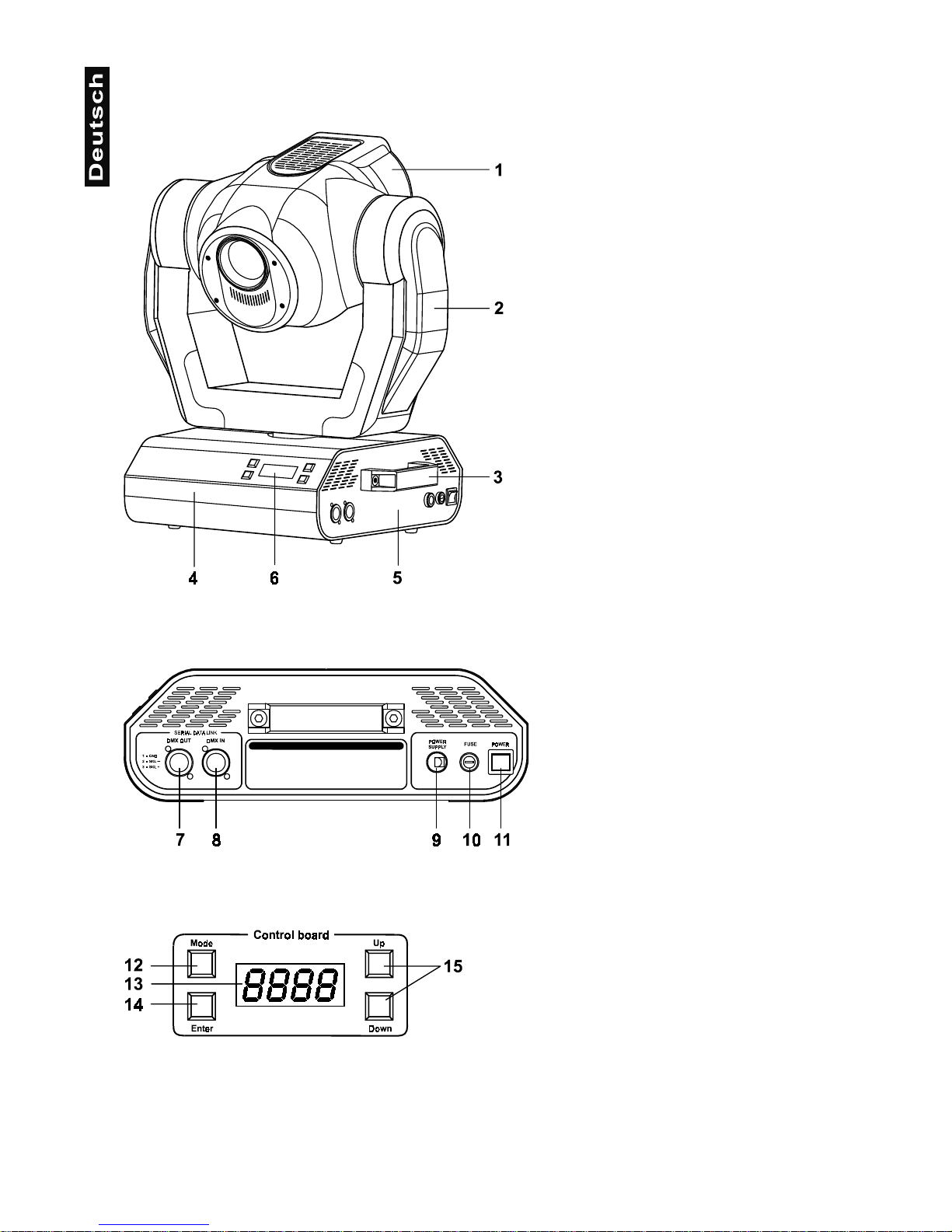
Geräteübersicht
1
- Projektorkopf
2
- Aufhängung
3
- Tragegriffe
4
- Base
5
- Base - Seite
6
- Steuereinheit
Base - Seite:
7
- DMX-Ausgang
8
- DMX-Eingang
9
- Netzanschluss
10
- Sicherungshalter
11
- Netzschalter
Control Board:
12
- Mode-Taste
13
- Display
14
- Enter-Taste
15
- Up-/Down-Tasten
Page 6
6
Sicherheit
Sicherheitshinweise
ACHTUNG!
Seien Sie besonders vorsichtig beim Umgang mit gefährlicher Netzspannung. Bei dieser Spannung können Sie einen lebensgefährlichen elektrischen Schlag erhalten!
Dieses Gerät hat das Werk in sicherheitstec h nis ch einwa n dfreiem Zustand verlassen. Um diesen Zustand zu
erhalten und einen gef ahrl osen Betr ieb sicher zus telle n, m uss der An wender di e S icherh eitsh inweis e und die
Warnvermerke unbedingt beachten, die in dieser Bedienungsanleitung enthalten sind.
Unbedingt lesen:
Bei Schäden, die durch Nic htbeachtung der Anleitung verursacht wer den, erlischt der Garantieanspruch. Für daraus resultierende Folgeschäden übernimmt der Hersteller keine Haftung.
Das Gerät darf nicht in Betrieb gen ommen werden, nachdem es von einem kalten in einen warmen Raum
gebracht wurde. Das dabei entstehende Kon dens wass er k ann unter Um ständen Ihr Ger ät zerstören. Lass en
Sie das Gerät solange uneingeschaltet, bis es Zimmertemperatur erreicht hat!
Der Aufbau entspricht der Schutzklasse I. Der Netzstecker darf nur an eine Schutzkontakt-Steckdose
angeschlossen werden.
Lassen Sie die Netzleitung n icht m it ander en Ka beln in Kon tak t komm en! Seien Sie vorsichtig beim Umgang
mit Netzleitungen und -anschlüssen. Fassen Sie diese Teile nie mit nassen Händen an!
Vergewissern Sie sich, dass die anzuschließend e Netzspannung nicht höher ist als auf der Rück seite angegeben. Stecken Sie die Netzleitung nur in gee ign ete Sc hukosteckdosen ein.
Achten Sie darauf, dass die Netzleitung nicht gequetscht oder durch scharfe Kanten beschädigt werden
kann. Überprüfen Sie das Gerät und die Netzleitung in regelmäßigen Abständen auf Beschädigungen.
Gerät bei Nichtbenutzu ng und vor jeder Reinigung vom Netz trennen! Fassen Sie dazu den Netzsteck er an
der Griffläche an und ziehen Sie niemals an der Netzleitung!
Bei der ersten Inbetriebnahme k ann es zu Rauch- und G eruchserzeug ung komm en. Hierbei hande lt es sich
nicht um eine Störung des Gerätes.
Achtung:
Gerät niemals während des Betriebes berühren. Gehäuse erhitzt sich!
Vermeiden Sie es, d as Gerät in kurzen Intervall en an- und auszuschalten ( z. B. Sekundentakt), da ansonsten die Lebensdauer der Lampe erheblich reduziert werden würde.
GESUNDHEITSRISIKO!
Blicken Sie niemals direkt in die Lichtquelle, da bei empfindlichen Menschen u. U.
epileptische Anfälle ausgelöst werden können (gilt besonders für Epileptiker)!
Beachten Sie bitte, dass Schäden, die durch manue lle Veränd erungen an dies em Gerät v erursacht werden,
nicht unter den Garantieanspruc h fal len .
Kinder und Laien vom Gerät fern halten!
Bestimmungsgemäße Verwendung
Bei diesem Gerät handelt es sich um einen kopfbewegten Scheinwerfer, mit dem sich dekorative Lichteffekte
erzeugen lassen. Dieses Produk t ist nur für den Anschluss an 230 V, 50 Hz W echselspannung zugelassen
und wurde ausschließlich zur Verwendung in Innenräumen konzipiert.
Page 7
7
Dieses Gerät ist für professionelle Anwendungen, z. B. auf Bühnen, in Diskotheken, Theatern etc.
vorgesehen.
Lichteffekte sind nicht für den D auerbetrieb konzipiert. D enken Sie daran, dass kons eque nte Betriebspausen
die Lebensdauer des Gerätes erhöhen.
Das Gerät darf niemals ohne Lampe in Betrieb genommen werden!
Vermeiden Sie Erschütter un gen un d jeglic he G e walta nwendung bei der Installation od er Inb etr ie bn ahme des
Gerätes.
Das Gerät darf niemals am Projektorkopf angehoben werden, da ansonsten die Mechanik beschädigt
werden könnte. Fassen Sie das Gerät immer an den Tragegriffen an.
Achten Sie bei der Wahl des Installationsor tes darauf, dass das Gerät nicht zu gr oßer Hitze, Feuchtigkeit
und Staub ausgesetzt wird. Verge wissern Sie sich, dass keine Ka bel frei herumliegen. Sie gefä hrden Ihre
eigene und die Sicherheit Dritter!
Der Abstand zwischen Lichtaustritt und der zu beleuchteten Fläche darf 1 Meter nicht unterschreiten!
Achten Sie bei der Projektorm ontage, beim Projektorabbau und bei der Durchführun g von Servicearbeiten
darauf, dass der Bereich unterhalb des Montageortes abgesperrt ist.
Der Projektor ist im mer mit einem geeig neten Sicher heitsfangseil zu sichern. D as Sicherhe itsfangseil m uss
an den dafür vorgesehenen Löchern eingehängt werden.
Betreiben Sie das Gerä t nur, nac hd em Sie sich vergewis se rt hab en, das s das Gehäuse fest vers c hlos sen ist
und alle nötigen Schrauben fest angezogen wurden.
Die Lampe darf niemals gezündet werden, wenn die Objektivlinse oder Gehäuseabdeckungen entfernt
wurden, da bei Entladungslampen Explosionsgefahr besteht und eine hohe UV-Strahlung auftritt, die zu
Verbrennungen führen kann.
Die maximale Umgebungstemperatur
t
a
darf niemals überschritten werden.
VORSICHT!
Die Linse muss gewechselt werden, wenn diese sichtbar beschädigt ist,
so dass ihre Wirksamkeit beeinträchtigt ist, z. B. durch Sprünge oder tiefe Kratzer!
Nehmen Sie das Gerät erst in Betrieb, nachdem Sie sich mit sein en Funktionen vertraut gemacht haben.
Lassen Sie das Gerät nicht von Pers onen bedie nen, die sich nicht mit dem Gerät ausk ennen. W enn Geräte
nicht mehr korrekt funktionieren, ist das meist das Ergebnis von unfachmännischer Bedienung!
VORSICHT!
Die Lampe muss gewechselt werden, wenn diese be-
schädigt ist oder sich durch Wärme verformt hat!
Soll das Gerät transpor tiert werden, verwenden S ie bitte die Origi nalverpackung, um T ransportschäden zu
vermeiden.
Beachten Sie bitte, dass eigenmächtige Veränderungen an dem Gerät aus Sicherheitsgründen verboten
sind.
Der Serienbarcode darf niemals vom Gerät entfernt werden, da ansonsten der Garantieanspruch erlischt.
Wird das Gerät anders v erwendet als in dieser Bedie nun gs anl eit un g bes c hri ebe n, kann dies zu Sc häd en am
Produkt führen und der G arantieanspruch erlischt. A ußer dem ist jede ander e V er wen dun g mit Gefahren, wie
z. B. Kurzschluss, Brand, elektrischem Schlag, Lampenexplosion, Abstürzen etc. verbunden.
Page 8
8
Installation
Einsetzen/Wechseln der Lampe
LEBENSGEFAHR!
Lampe nur bei ausgeschaltetem Gerät einsetzen!
Netzstecker ziehen!
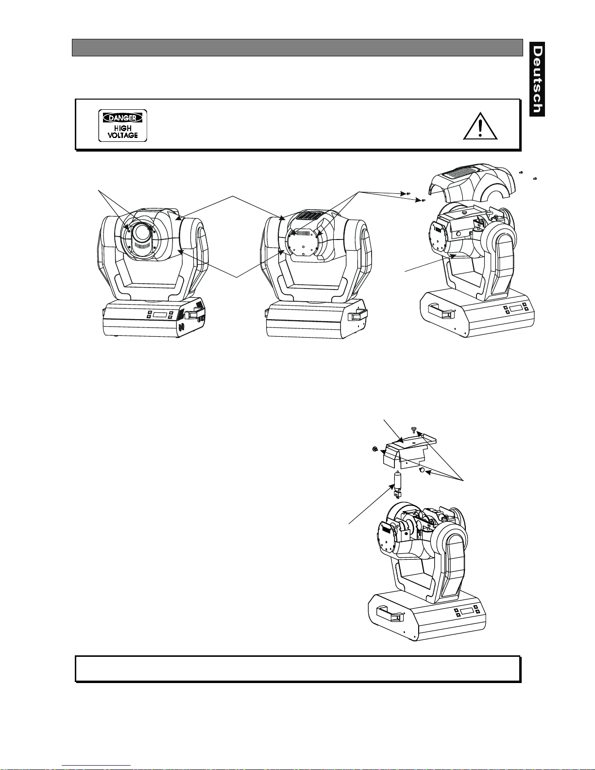
Zum Einsetzen der Lampe (MSD 23 0 V/250 W oder MSD 2 30 V/200 W ) öffnen S ie den G ehäusedeck el des
Kopfes wie in oben stehe nder Zeichnung. Lösen Sie dazu die Kreuzschlitzschrau ben an der Vorder- und
Rückseite des Gehäusedeckels.
Öffnen Sie danach die kleine Lampenabdeckung, indem
Sie die drei Befestigungsschrauben wie in nachstehender
Zeichnung lösen.
Wird eine defekte Lampe ausgetauscht, entfernen Sie
zunächst die defekte Lampe aus dem Lampensockel.
Setzen Sie keine Lampe mit einer höheren
Leistungsangabe ein. Lam pen mit einer höheren Leistung
entwickeln höhere Temperaturen, für die das Gerät nicht
ausgelegt ist. Bei Zuwiderhandlungen erlischt die Garantie.
Setzen Sie nun die Lampe ein. Vermeiden Sie es, den
Glaskörper mit bloßen Händen zu berühren. Beach ten Sie
auch unbedingt die Hinweise des Lampenherstellers.
Vergewissern Sie sic h, dass die Lam pe auch r ichtig fest in
der Fassung sitzt.
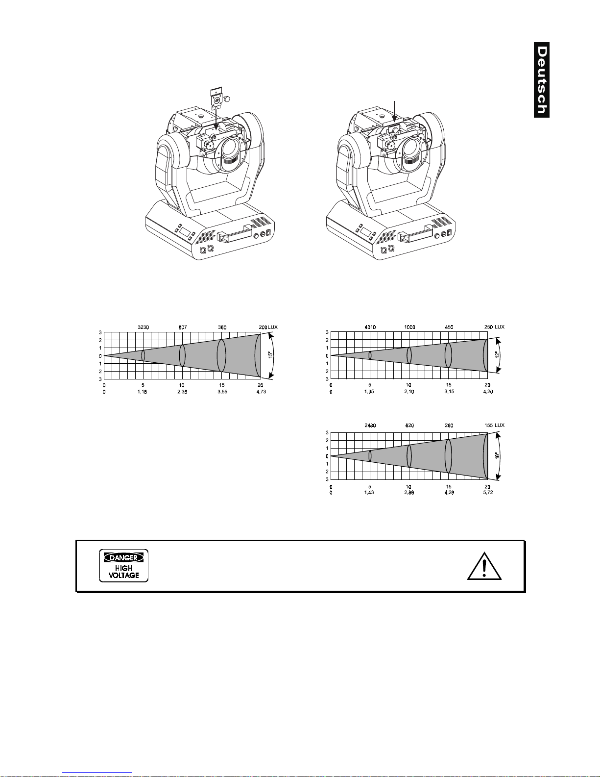
Stellen Sie den optimalen Abstand zwischen Lampe und
Linse durch Drehen der Sc hraube
"A"
ein (bitte beachten
Sie dazu auch nachstehende Zeic hn ung) .
Schließen Sie die Lampenabdeckung wieder und ziehen
Sie die Befestigungschrauben fest. Setzen Sie den
Betriebsstundenzähler der Lampe („LAti“) wieder auf 0
zurück bevor Sie d ie Lampe zünden. Drücken und Ha lten
Sie dazu die Up- und Down-Taste gleichzeitig und
bestätigen Sie dann mit der Enter-Taste.
Schalten Sie das Gerät nur bei geschlossenem Gehäuse ein!
Unterseite
Unterseite
Oberseite
2 Kreuzschlitzschrauben
2 Kreuzschlitzschrauben
3 Befestigungsschrauben
Lampe
Lampenabdeckung
Page 9
9
Lampenjustierung
Der Lampenhalter des Gerätes wird ab W erk justiert. Da sich die zu verwendenden L ampen von Hersteller
zu Hersteller untersc heiden, k ann es u. U. not wendig s ein, die Pos ition des Lam penhalter s nach zujustier en.
Die Lampe muss z. B. nachjustiert werden, wen n das Licht innerhalb des Strahls nicht g leichmäßig verteilt
zu sein scheint.
Zünden Sie die Lampe un d fokussieren Sie den Lichtstrahl auf einer ebenen Oberfläche (W and). Da der
optimale Abstand zwischen Lampe und Linse bereits während der Installation über die Schraube
"A"
eingestellt wurde, muss nur noch der „Hot Spot“ (d. i. der hellste Teil des Lichtstrahls) zentriert werden.
Drehen Sie dazu an Schraube „B“.
Wenn der Hot Spot zu hell erscheint, können Sie dessen Intensität abschwächen, indem Sie die Lampe
näher zum Reflektor hinbewegen. Dr ehe n Sie dazu an Sc hr au be
"A"
, bis das Licht gleichmäßig verteilt ist.
Wenn das Licht am äußeren Rand des Strahls heller erschei nt als in der Mitte, befinde t sich die Lampe zu
nah am Reflektor. Bewegen Sie in diesem Fall die Lampe vom Reflektor weg, bis das Licht gleichmäßig
verteilt ist und der Strahl hell genug erscheint.
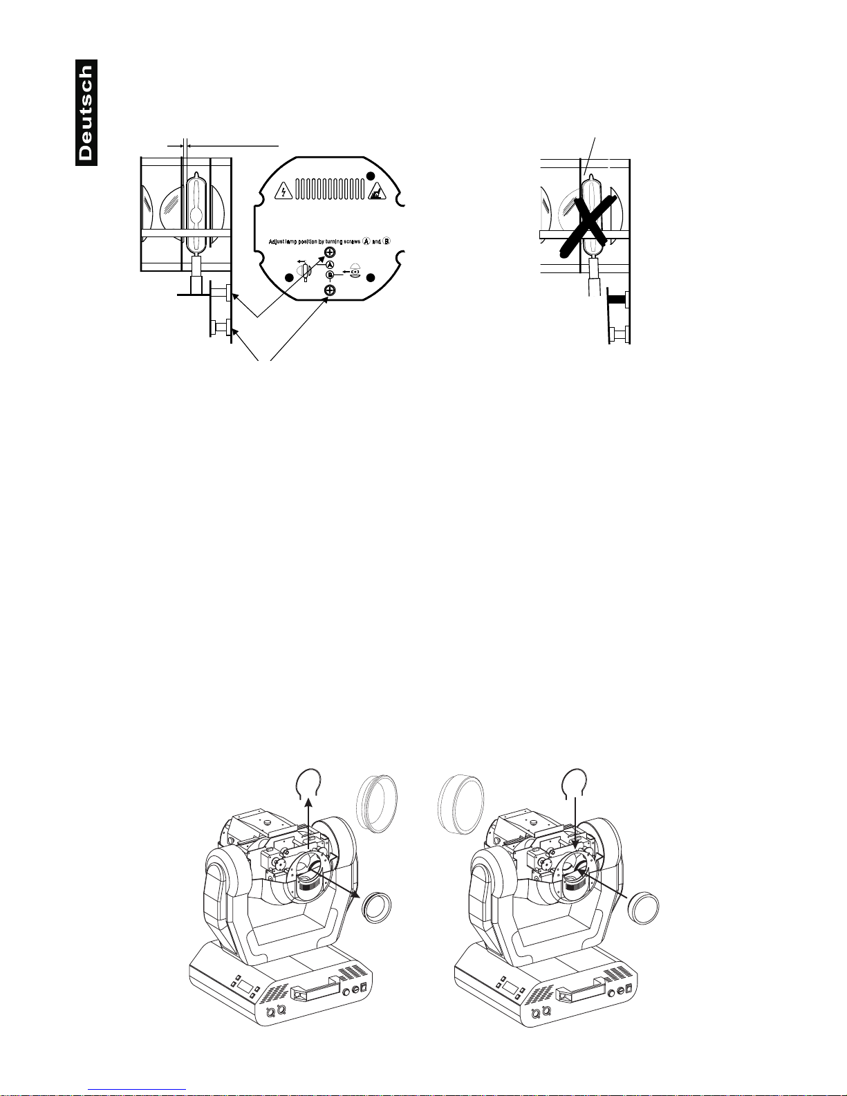
Installation einer optionalen Linse
Das Gerät wird standardmäßig m it einer 15°-Linse geliefert. W enn Sie eine optionale 12°- oder 18°-Linse
einsetzen möchten, gehen Sie wie folgt vor:
Optionale 12°-Linse:
Entfernen Sie den Sprengring der 15°-Linse mit einem geeigneten Werkzeug. Entnehmen Sie die Linse.
Setzen Sie die optionale 12°-Linse ein und befestigen Sie sie mit dem Sprengring.
15°-Linse Optionale 12°-Linse
Schraube "A"
Optimalen Abstand zur Linse einhalten!
-
RICHTIG FALSCH
"
"
Page 10
10
Optionale 18°-Linse:
Lösen Sie die Rändelschraube an dem Blech des Lichtaustritts . Setzen Sie die opt ionale 18°-Linse e in und
befestigen Sie sie mit der Rändelschraube.
Strahlenverlauf:
Einsetzen/Austauschen von Gobos
LEBENSGEFAHR!
Gobos nur bei ausgeschaltetem Gerät austauschen
Netzstecker ziehen!
Öffnen Sie den Gehäusedeckel des Kopfes, indem Sie die Kreuzschlitzschrauben an der Vorder- und
Rückseite des Gehäusedeckels lösen.
Wenn Sie andere Formen und Muster als die Standard-Gobos verwenden möchten, oder Gobos
ausgetauscht werden sollen, ge hen Si e wie fol gt vor:
Statisches Goborad:
Drücken Sie das gewünschte Gobo vorsichtig aus der Halterung. Achten Sie dabei darauf, dass Sie die
Klammern möglichst nicht abbiegen.
Standard 15°-Linse
Optionale 12°-Linse
Beam opening (m)Beam opening (m)
Optionale 18°-Linse
Beam opening (m)
Page 11
11
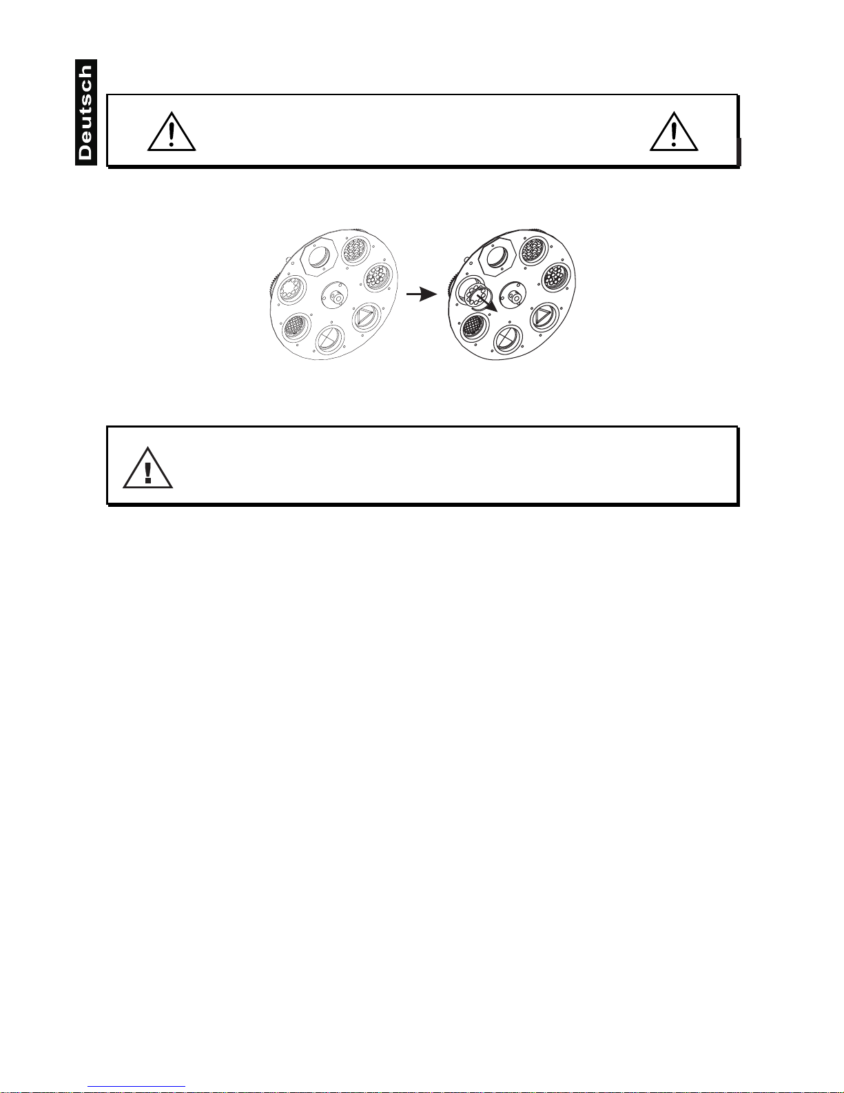
Rotierendes Goborad:
ACHTUNG!
Niemals die Schrauben der rotierenden Gobos lösen,
da ansonsten die Kugellager geöffnet werden!
Entfernen Sie den Sprengr ing mit einem geeigneten W erkzeug. Entnehmen Sie das Go bo und setzen Sie
das neue Gobo ein. Drücken Sie den Sprengring zusammen und setzen Sie ihn vor das Gobo.
Projektormontage
LEBENSGEFAHR!
Bei der Installation sind insbesondere die Bestimmungen der BGV C1 (vormals VBG 70)
und DIN VDE 0711-217 zu beachten! Die Installation darf nur vom autorisierten Fachhandel ausgeführt werden!
Die Aufhängevorrichtungen des Projektors muss so gebaut und bemessen sein, dass sie 1 Stunde lang
ohne dauernde schädliche Deformierung das 10-fache der Nutzlast aushalten kann.
Die Installation muss immer mit einer zweiten, unabhängigen Aufhängung, z. B. ei nem geeigneten Fangnetz,
erfolgen. Diese zweite Aufhängung muss so beschaffen und angebracht sein, dass im Fehlerfall der
Hauptaufhängung kein Teil der Installation herabfallen kann.
Während des Auf-, Um- und Abbaus ist der unnötige Aufenthalt im Bereich von Bewegungsflächen, auf
Beleuchterbrücken, unter hochgelegenen Arbeitsplätzen sowie an sonstigen Gefahrbereichen verboten.
Der Unternehmer hat daf ür zu sorgen, dass sic herheitstechnische un d maschinentechnisc he Einrichtungen
vor der ersten Inbetriebnahme und nach wesentlichen Änderungen vor der Wiederinbetriebnahme durch
Sachverständige geprüft werden.
Der Unternehmer hat daf ür zu sorgen, dass sic herheitstechnische un d maschinentechnisc he Einrichtungen
mindestens alle vier Jahre durch einen Sachverständigen im Umfang der Abnahmeprüfung geprüft werden.
Der Unternehmer hat daf ür zu sorgen, dass sic herheitstechnische un d maschinentechnisc he Einrichtungen
mindestens einmal jährlich durch einen Sachkundigen geprüft werden.
Vorgehensweise:
Der Projektor sollte idealerweise außerhalb des Aufenthaltsbereiches von Personen installiert werden.
WICHTIG! ÜBERKOPFMONTAGE ERFORDERT EIN HOHES MAß AN ERFAHRUNG. Dies beinhaltet (aber
beschränkt sich nicht al lein auf) Berechnungen zur Def inition der Tragfähigkeit, verwen detes Installationsmaterial und regelmäßige Sicherheitsinspektionen des verwendeten Materials und des Projektors.
Versuchen Sie niemals, die Ins tallation selbst vorzunehmen, wenn Sie nicht über eine solc he Qualifikation
verfügen, sondern b eauftragen Sie ei nen profession ellen Installateur . Unsachgem äße Installationen können
zu Verletzungen und/oder zur Besch ädi gun g von E ige ntum führen.
Der Projektor muss außerhalb des Handbereichs von Personen installiert werden.
Page 12

12
Wenn der Projektor von der D ec ke oder hochliegenden Tr äger n etc. abgehängt werden soll, m us s im m er m it
Traversensystemen gearbeitet werden. Der Projektor darf niemals frei schwingend im Raum befestigt
werden.
Achtung:
Projektoren k önnen beim Herabstürzen erheb liche Verletzungen verursachen! W enn Sie Zweifel
an der Sicherheit einer möglichen Installationsform haben, installieren Sie den Projektor NICHT!
Vergewissern Sie sich vor der Montage, dass die Montagefläche mindestens d ie 10-fache Punktbelastung
des Eigengewichtes des Projektors aushalten kann.
Achten Sie bei der Installation des Gerätes bitte darauf, dass sich im Abstand
von mind. 0,5 m keine leicht entflammbaren Materialien (Deko, etc.) befinden.
BRANDGEFAHR!
ACHTUNG!
Montieren Sie den Projektor ausschließlich über zwei geeignete Haken. Bitte
beachten Sie auch die Installationshinweise auf der Unterseite der
Base. Achten Sie darauf, dass das Gerät sicher befestigt wird.
Vergewissern Sie sich, dass die Verankerung stabil ist.
Das Gerät kann direkt auf den Boden gestellt
werden oder in jeder möglichen Position im
Trussing installiert werden, ohne seine
funktionellen Eigenschaf ten zu verändern.
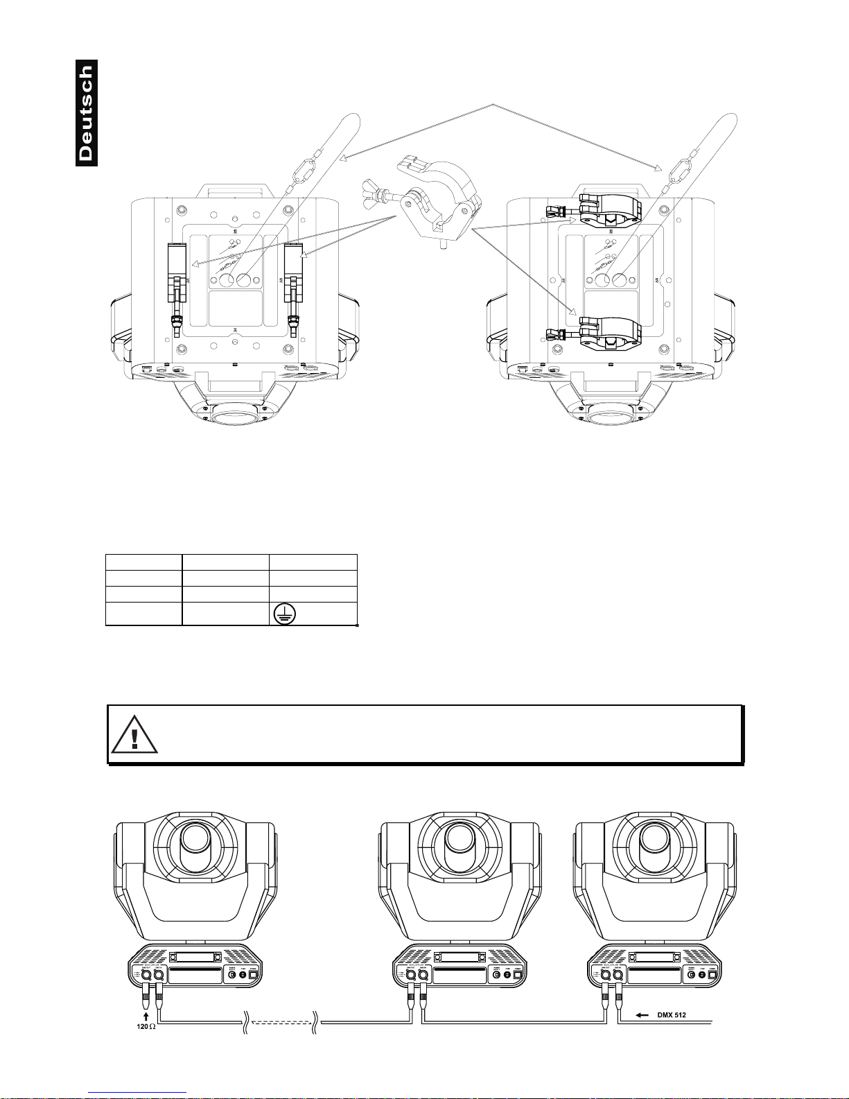
Die Projektorbase lässt sich auf zwei
verschiedene Arten montier en. Verwenden Sie
nur Haken mit M10 oder M8 Schrauben.
Verschrauben Sie die Haken an den
Befestigungspunkten A1 und A2 oder B1 und
B2. Verwenden Sie keine ander e Kombination
der Befestigungspunkte. Ziehen Sie die
Schrauben gut fest.
Sichern Sie den Projektor bei
Überkopfmontage immer mit einem
Sicherheitsfangsei l, d as mindestens für das 10fache Gewicht des Gerätes ausgelegt ist. Es
dürfen nur Fangseile mit Schraubkarabinern
vewendet werden. Hängen Sie das
Sicherheitsfangseil an dem dafür
vorgesehenen Loch im Bodenblech ein und
führen Sie es über die Traverse etc. Hängen
Sie das Ende in dem Karabiner ein und ziehen
Sie die Feststellmutter gut fest.
Page 13
13
Anschluss ans Netz
Schließen Sie das Gerät über den Netzstecker ans Netz an.
Die Belegung der Anschlussleitungen ist wie folgt:
Leitung Pin International
Braun Außenleiter L
Blau Neutralleiter N
Gelb/Grün Schutzleiter
Der Schutzleiter muss unbedingt angeschlossen werden!
Lichteffekte sollten im Allgemeinen nicht über Dimmerpacks geschaltet werden.
LEBENSGEFAHR!
Vor der ersten Inbetriebnahme muss die Einrichtung durch einen Sachverständigen geprüft werden!
Anschluss an den DMX-512 Controller / Verbindung Projektor - Projektor
Sicherheitsfangseil
Haken
Page 14

14
Achten Sie darauf, dass die Adern der Datenleitung an keiner
Stelle miteinander in Kontakt treten. Die Geräte werden
ansonsten nicht bzw. nicht korrekt funktionieren.
Die Verbindung zwis chen Controller und Projektor sowie zwische n den einzelnen Geräten muss mit einem
zweipoligen geschirmten Kabel erfolgen. Die Steckverbindung geht über 3-polige XLR-Stecker und Kupplungen.
Belegung der XLR-Verbindung:
Wenn Sie die empfohlenen FUTURELIGHT-Controller verwenden, können Sie den DMX-Ausgang des
Controllers direkt mit dem DMX-Eingang des ersten Gerätes der DMX-Kette verbinden. Sollen DMXController mit anderen XLR-Ausgängen angeschlossen werden, müssen Adapterkabel verwendet werden.
Aufbau einer seriellen DMX-Kette:
Schließen Sie den DMX-Ausgan g des ersten G erätes der Kette a n den D MX- Eingan g des näc hste n Gerät es
an. Verbinden Sie immer einen Ausgang mit dem Eingang des nächsten Gerätes bis alle Geräte
angeschlossen sind.
Achtung:
Am letzten Projektor muss die DMX-Leitung durch einen Abschlusswiderstand abgeschlossen
werden. Dazu wird ein 120
Ω
Widerstand in einen XLR-Stecker zwis c he n S ign al ( –) un d S ig nal (+) e ing el ötet
und in den DMX-Ausgang am letzten Gerät gesteckt.
Page 15
15
DMX-Protokoll
Funktionen der Steuerkanäle
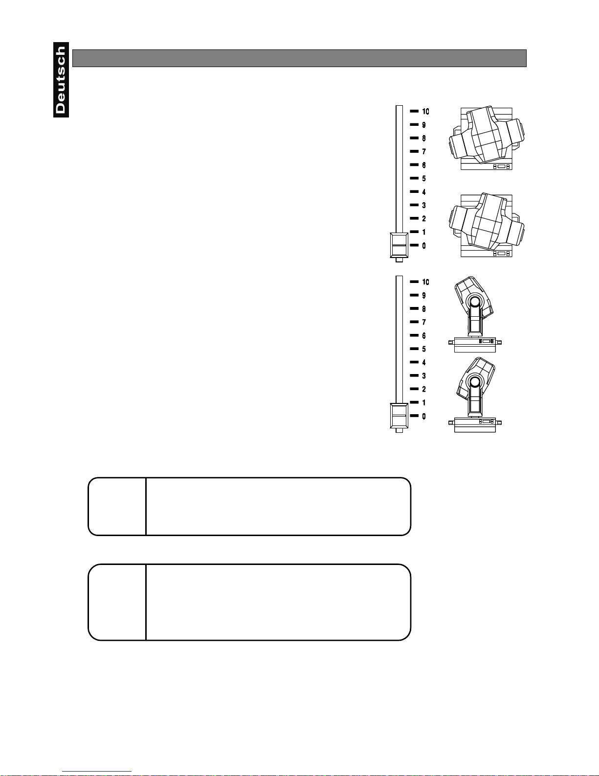
Steuerkanal 1 - Drehbewegung (Pan)
Wenn Sie den Regler verschieben, bewegen Sie den Kopf horizontal
(PAN).
Allmähliches Einst ellen des Kopfes bei langsamen Schie ben des Reglers
(0-255, 128-Mitte).
Der Kopf lässt sich um 530° drehen und kann in jeder gewünschten
Position angehalten werden.
Steuerkanal 2 - Kippbewegung (Tilt)
Wenn Sie den Regler verschieben, bewegen Sie den Kopf vertikal (TILT).
Allmähliches Einst ellen des Kopfes bei langsamen Schie ben des Reglers
(0-255, 128-Mitte).
Der Kopf lässt sich um 280° kippen und kann in jeder gewünschten
Position angehalten werden.
Steuerkanal 3 - Pan 16 Bit
Steuerkanal 4 - Tilt 16 Bit
Steuerkanal 5 - Pan / Tilt Geschwindigkeit
0 Maximalgeschwindigkeit (Tracking Modus)
1 Maximalgeschwindigkeit (Vektor-Modus)
249 Minimalgeschwindigkeit (Vektor-Modus)
250-255 Maximalgeschwindigkeit, Blackout während PAN-,
TILT-Bewegung und Farbe wechseln (Tracking Modus)
Steuerkanal 6 - Lampe, Reset, Lüfter
0 Offen, Lüfter auf Höchstgeschwindigkeit
127 Offen, Lüfter auf Minimalgeschwindigkeit
128-139 Lampe einschalten, Reset, offen
140-239 Ohne Funktion
230-239 Lampe wird nach 3 Sekunden abgeschaltet
240-255 Ohne Funktion
Steuerkanal 7 - Farben
Lineare Farbänderung gemäß der Bewegung des Reglers.
Sie können den Farbwechsl er an jeder gewü nschten Pos ition a nhalten. Sie k önnen ebenf alls zwisc hen zwe i
Farben anhalten und so zweifarb ige Str ah le n er zeu gen.
Zwischen 128 und 190 und zwischen 193 und 255 dreht sich der Farbwechsler stän dig - der so genannte
Rainbow-Effekt entsteht.
Page 16
16
0 Offen/weiß
10 Türkis
21 Rot
32 Cyan
42 Grün
53 Magenta
64 Hellblau
74 Gelb
85 Grün
96 Pink
106 Blau
117 Orange
128 - 190 Rainboweffekt vorwärts mit absteigender Geschwindigkeit
191 - 192 Keine Rotation
193 - 255 Rainboweffekt rückwärts mit zunehmender Geschwindigkeit
Steuerkanal 8 - Ohne Funktion
Steuerkanal 9 - Prismenrad
0 - 95 Offen
96 - 255 3-fach Prisma
160 - 255 Prismen/Gobo-Makros
160 - 167 Makro 1
168 - 175 Makro 2
176 - 183 Makro 3
184 - 191 Makro 4
192 - 199 Makro 5
200 - 207 Makro 6
208 - 215 Makro 7
216 - 223 Makro 8
224 - 231 Makro 9
232 - 239 Makro 10
240 - 247 Makro 11
248 - 255 Makro 12
Steuerkanal 10 - Rotierendes 3-fach Prisma
0 Keine Rotation
1 - 126 Rotation vorwärts mit absteigender Geschwindigkeit
127 - 128 Keine Rotation
129 - 255 Rotation rückwärts mit zunehmender Geschwindigkeit
Steuerkanal 11 - Rotierende Gobos
0 - 31 Offen
32 - 63 Rot. Gobo 1 (Multicolor Dichro-Gobo)
64 - 95 Rot. Gobo 2 (Glas)
96 - 127 Rot. Gobo 3 (Metall)
128 - 159 Rot. Gobo 4 (Metall)
160 - 191 Rot. Gobo 5 (Metall)
192 - 223 Rot. Gobo 6 (Metall)
224 - 255 Rotierendes Goborad mit ständiger Rotation von langsam bis schnell
Page 17
17
Steuerkanal 12 - Indizieren der rotierenden Gobos, Goborotation
0 - 127 Goboindizierung
128 - 191 Goborotation vorwärts von schnell bis langsam
192 Keine Rotation
193 - 255 Goborotation rückwärts von langsam bis schnell
Steuerkanal 13 - Ohne Funktion
Steuerkanal 14 - Fokus
0 - 255 Allmähliche Einstellung von weit bis nah
Steuerkanal 15 - Shutter, Strobe
0 - 31 Shutter geschlossen
32 - 63 Keine Funktion (Shutter offen)
64 - 95 Strobe-Effekt langsam bis schnell (max. 10 Blitze/Sekunde)
96 - 127 Keine Funktion (Shutter offen)
128 - 159 Puls-Effekt in Sequenzen
160 - 191 Keine Funktion (Shutter offen)
192 - 223 Strobe-Effekt über Zufallsgenerator langsam bis schnell
224 - 255 Keine Funktion (Shutter offen)
Steuerkanal 16 - Dimmerintensität
0 - 255 Allmähliche Einstellung der Dimmerintensität von 0 bis 100 %
Funktionen der Steuerkanäle - 8 Bit-Protokoll:
XMD
lennahC
1234567 8 9 0111213141
noitcnuF
NAPTLIT
TLIT/NAP
DEEPS
NAF
FFO/NO
PMAL
SRUOLOC-MSIRP
MSIRP
NOITATOR
GNITATOR
SOBOG
OBOG
NOITATOR
-SUCOFOBORTSREMMID
Adressierung des Projektors
Über das Control Boar d am Pr ojektork opf können Si e die DMX Startadr esse defin ieren. Di e Star tadress e ist
der erste Kanal, auf den der Projektor auf Signale vom Controller reagiert.
Wenn Sie die Startadresse z. B. auf 5 definieren belegt der Projektor die Steuerkanäle 5 bis 20.
Bitte vergewissern Sie sich, dass sich die Steuerkanäle nicht m it anderen Geräten überlapp en, damit der
MH-660 korrekt und unabhängig von anderen Geräten in der DMX-Verbindung funktioniert.
Werden mehrere MH-660 auf eine Adresse definiert, arbeiten sie synchron.
Vorgehensweise:
1. Schalten Sie den M H-660 ein und warten Sie, bis das Gerät den Setup beendet hat (auf dem Display
blinkt „rSt“).
2. Drücken Sie die Mod e-T aste, um in das Hau ptm enü zu ge lange n. Ü ber die U p- un d Down-T as ten k önnen
Sie sich durch das Menü beweg en, bis Sie den auf dem Dis play „A001“ erscheint. Bestätigen Sie mit der
Enter-Taste, und der Buchstabe
"A"
beginnt zu blinken.
3. Drücken Sie die Up-/Down-Tasten, um die gewünschte Startadresse auszuwählen. Drücken Sie die EnterTaste zur Bestätigung oder die Mode-Taste um abzubrechen.
Ansteuerung:
Nachdem Sie die Startadresse definiert haben, können Sie den MH-660 über Ihren Controller ansteuern.
Page 18

18
Bitte beachten Sie:
1. Schalten Sie den MH-660 ein. Das Gerät prüft, ob DMX-512 Daten empfangen werden oder nicht. Werden
keine Daten empfangen, beginnt die Anzeige zu blinken und es erscheint „A001“ mit der definierten
Startadresse.
Die Fehlermeldung erscheint
-wenn kein 3-poliges XLR- Kabel (DMX Signalkabel vom Controller) in die DMX-Eingangsbuchs e des MH660 gesteckt wurde.
-wenn der Controller ausgeschaltet oder defekt ist.
-das Kabel oder der Stecker defekt ist oder das Signalkabel nicht richtig eingesteckt ist.
Achtung:
Am letzten Projektor muss die DMX-Leitung durch einen 120
Ω
. Widerstand abgeschlossen
werden damit die Geräte korrekt funktionieren.
Fernsteuerbare Funktionen
Lampe
Der MH-660 wird mit einer MSD 230 V/250 W GY-9,5 oder MSD 230 V/200 W GY-9,5 Lampe betrieben.
Ein Relais im Projek tor ermöglicht die Sc haltung der Lam pe über das Control B oard am Projektork opf oder
über den angeschlossenen Controller.
Lampe über das Control Board schalten
1. Schalten Sie den MH-660 ein und warten Sie, bis das Gerät den Reset beendet hat.
2. Drücken Sie die Mod e-T aste, um in das Hau ptm enü zu ge la ngen. Ü ber die U p- un d Down- Tas ten k önnen
Sie sich durch das Menü bewegen, bis Sie den auf dem Display
„LAMP“
erscheint. Bestätigen Sie mit der
Enter-Taste.
3. Drücken Sie die Up-/Down-Tasten, um
„ON“
(Lampe ein) oder um
„OFF“
(Lampe aus) zu wählen.
Drücken Sie die Enter-Taste zur Bestät igung oder die Mode-Taste um abzubrechen.
Achtung:
Wenn Sie die Lam pe über das Control Board eing eschalten haben und den MH-660 aus- und wieder einschalten, schaltet das Gerät automatisch die Lampe ein.
Wenn Sie die Lampe über das Control Board ausgeschalten haben und den MH-660 aus- und wieder
einschalten, bleibt die Lampe aus. In diesem Fall müssen Si e dann die Lam pe über das C ontrol Boar d oder
über den externen Controller einschalten.
Bitte beachten Sie, dass es sich be i der verwend eten Lampe um eine nicht heiß zündfähige Lam pe handelt.
Dies bedeutet, dass die Lam pe vollständig abgek ühlt sein muss, bevor Sie wieder gezündet werden k ann.
Nachdem die Lampe abgeschaltet wurde, müssen Sie deshalb bei maximaler Lüftergeschwindigkeit 5
Minuten warten, bis Sie die Lampe wieder zünden können. Wird versucht, die Lampe vor Ablauf der
Abkühlzeit zu zünden s peichert der Projektor dies e Information und zündet d ie Lampe selbständig, soba ld
diese abgekühlt ist. In diesem Fall erscheint auf dem Display die Meldung
„HEAt“
. Lässt sich die Lampe
siebenmal nicht zünden, erscheint auf dem Display „
LA.Er
“. Diese Meldung bedeutet, dass die Lampe
beschädigt sein kann, überhaupt keine Lampe eingesetzt wurde, oder dass es sich um einen Defek t am
Starter oder an der Drosselspule handelt.
Farbrad
Der MH-660 verfügt über ein Farbrad mit 12 Positionen - 11 dichroitische Farben und eine offene P osition.
Das Rad kann jederzeit zwis chen zwei Farben angehalten werden. A ußerdem lässt sich das Farbrad mit
verschiedenen Geschwindigkeiten rotieren - der so genannte Rainbow-Effekt entsteht.
Rotierendes Goborad
Dieses Rad verfügt über 4 Metallgobos, 1 Glasgobo, 1 Dichro-Gobo und 1 offene Position. Die Gobos lassen
sich in beide Richtungen rotieren, sind indizierbar und können mit verschiedenen Geschwindigkeiten in
beide Richtungen rotieren. Das Multicolor-Gobo mit cyan, magenta und gelb Farbanteilen lässt sich für
besondere Effekte mit dem F arbr ad mischen. Alle Gobos lassen s ich u nter e ina nd er austa us c hen. Di e Gobos
haben einen Außendurchmesser von 27 mm und einen Imagedurchmesser von 23 mm.
Rotierendes 3-fach Prisma
Das rotierende 3-fach Prisma lässt sich bei verschiedenen Geschwindigkeiten in beide Richtungen rotieren.
Fokus
Über den motorischen Fokus lässt sich die Projektion stufenlos scharfstellen.
Page 19
19
Dimmer / Shutter / Strobe
Die Shuttereinheit ermöglicht Strobe-Eff ekte von 1 b is 10 Blitze n pro Sek unde. Über die Shuttereinh eit lässt
sich der Lichtaustritt stufenlos von 0-100 % dimmen.
Lüfter
Der MH-660 wird über zwei Axiallüfter im Projektorkopf und einen in der Base gekühlt. Die Lüftergeschwindigkeit (und dam it natürlich auc h das Geräus ch) kann stuf enlos geregelt werden und lässt sic h für
leise Vorführungen auf ein Minimum reduzieren. Eine ni edrige Lüftergeschwindigkeit senkt den Kühlungseffekt des Lüfters wodurch die Innentemperatur des Projektors ansteigt.
1. „HIGH“- Lüftergeschwindigkeit maximal
Der Projektor wird mit maximaler Lüfterleistung gekühlt.
2. „reG“ - automatische Anpassung der Lüftergeschwindigkeit
Ab einer gewissen Temperatur wird die Lüftergeschwindigkeit automatisch erhöht, um einen Ausfall des
Gerätes zu verhinder n. Diese Aut omatik kann sich bis zu s ieben Mal wied erholen, b is die Innnentem peratur
wieder ein unkritischen Niveau erreicht hat.
3. „Lo.HI“- Lüftergeschwindigkeit niedrig/maximal
Die Lüftergeschwindigk eit bleibt so lange niedrig, bis die Innentem peratur des Projektors den Max imalwert
erreicht hat. Der Projektor schaltet dann automatisch auf maximale Lüfterleistung.
4. „Lo.OF“ - Lüftergeschwindigkeit niedrig/Lampenabschaltung
Die Lüftergeschwindigk eit bleibt so lange niedrig, bis die Innentem peratur des Projektors den Max imalwert
überschritten wird. Der Projektor schaltet dann automatisch die Lampe ab.
Control Board
Das Control Board bef in det sich am Projektork opf und biet et mehrere Möglichk eiten. So lassen s ic h z. B. die
DMX-Startadresse eingeben , die Betriebsstunden der Lampe und des Projektors ablesen, die Lam pe einund ausschalten, ein Demonstrationsprogramm abspielen oder ein Reset durchführen. Außerdem lassen
sich Spezialfunktionen für manuelle Steuerung und zu Servicezwecken abrufen.
Über die Mode-Taste gelangen Sie ins Hauptm enü. Drücken Sie diese T aste solange, bis auf dem Display
„A001“ mit der definierten Startadress e erscheint. Über d ie Up-/Do wn-Tasten k önnen Sie sich in nerhalb des
Menüs bewegen.
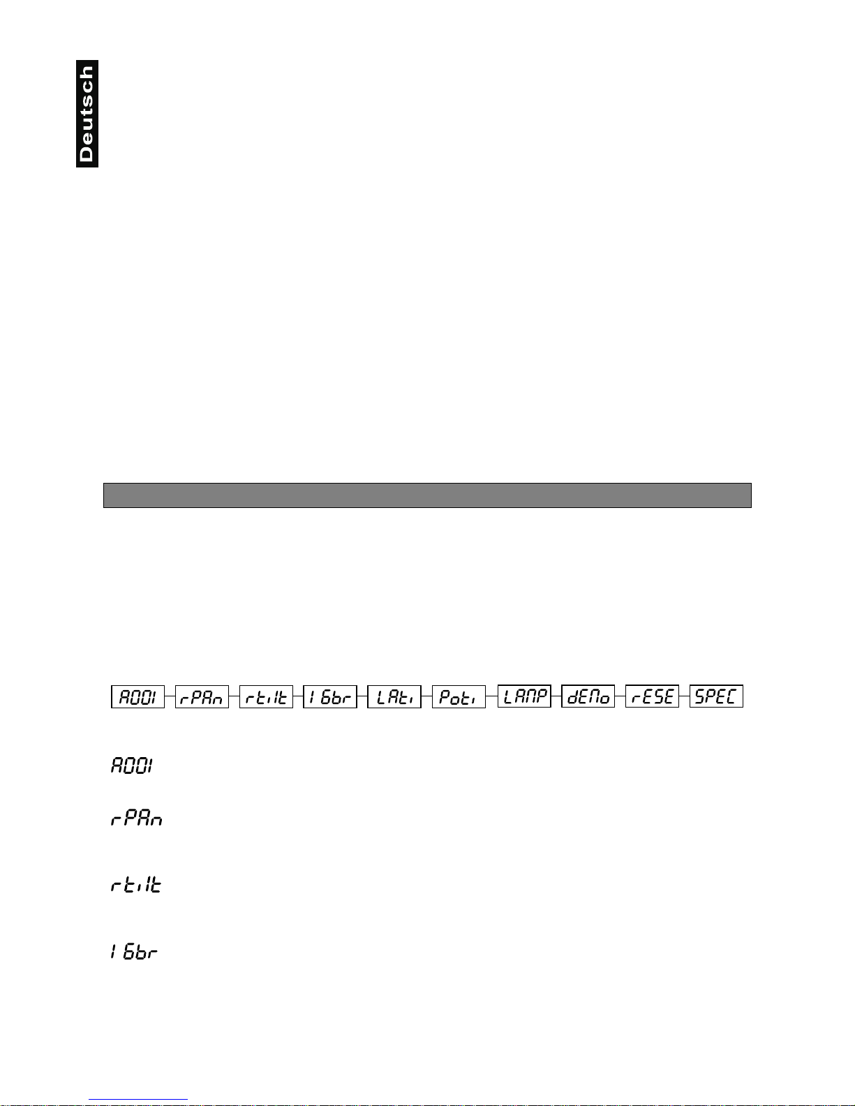
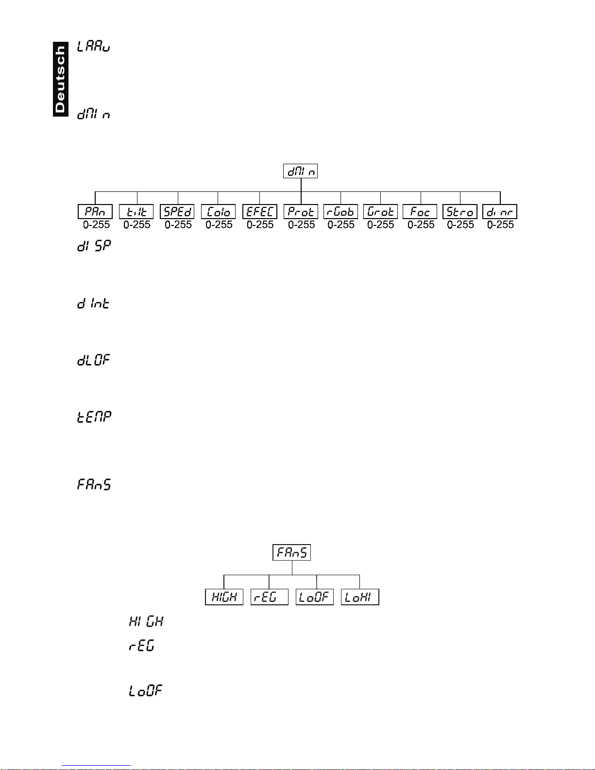
Auf dem Display erscheinen nacheinander:
A001, rPAn, r Tilt, 16br, Lati, Poti, LAMP, dEMo, rESE, SPEC
Zur Auswahl des gewünscht en Men üpu nktes drücken Sie die Ent er - T as te. Die j e wei lig en F unktionen werden
im Folgenden beschrieben.
Hauptfunktionen
- DMX-512 Startadresse einstellen:
Der Buchstabe
"A"
blinkt. Drücken Sie d ie Up-/Down-Tasten, um die gewünscht e Startadresse (001-496)
einzustellen. Drücken Sie die Enter-Taste zur Bestätigung oder die Mode-Taste, um abzubrechen.
- Panumkehrung:
Mit dieser Funktion lässt sich die Pan- Bewegung umkehren. Drücken Sie die Up-/Down-T asten, um
„ON“
oder
„OFF“
einzustellen. Drücken Sie die Enter-Taste zur Bestätigung oder die Mode-Taste, um
abzubrechen.
- Tiltumkehrung:
Mit dieser Funktion lässt sich die Tilt-Bewegung umkehren. Drücken Sie die Up-/Down-T asten, um
„ON“
oder
„OFF“
einzustellen. Drücken Sie die Enter-Taste zur Bestätigung oder die Mode-Taste, um
abzubrechen.
- Auflösung:
Mit dieser Funktion lässt sich die Auflös ung der Kopfbewe gung von 8 a uf 16 Bit um stellen. Drück en Sie die
Up-/Down-Tasten, um
„ON“
(16 Bit) oder
„OFF“
(8 Bit) einzustellen. Drücken Sie die Enter-Taste zur
Bestätigung oder die Mode-Taste, um abzubrechen.
Achtung:
Wenn Sie den Projektor auf 16 Bit ums tellen, beleg t der Projek tor 16 DMX-Kanä le. Bei der Einstellun g 8 Bit
Page 20
20
belegt er nur 14 DMX-Kanäle. Bitte informieren Sie sich über die DMX-Kanäle im DMX-Protokoll.
- Betriebsstunden der Lampe:
Mit dieser Funktion können die Betriebs stunden der Lampe abgefr agt werden. Drücken Sie die Enter-Taste
oder die Mode-Taste, um zum Hauptmenü zurückzukehren. Um den Betriebsstundenzähler auf 0
zurückzusetzen halten Sie bitte die Up- und Down-Taste und drücken Sie die Enter-Taste.
- Betriebsstundenzähler:
Mit dieser Funktion k önnen die Betriebsstunden des Proj ektors abgefragt werden. Drücken Sie die EnterTaste oder die Mode-Taste, um zum Hauptmenü zurückzukehren.
- Lampe einschalten:
Drücken Sie die Up-/Down- Tasten, um
„ON“
(Lampe an) oder
„OFF“
(Lampe aus) einzuste llen. Drücken
Sie die Enter-Taste zur Bestätigung oder die Mode-Taste, um abzubrechen.
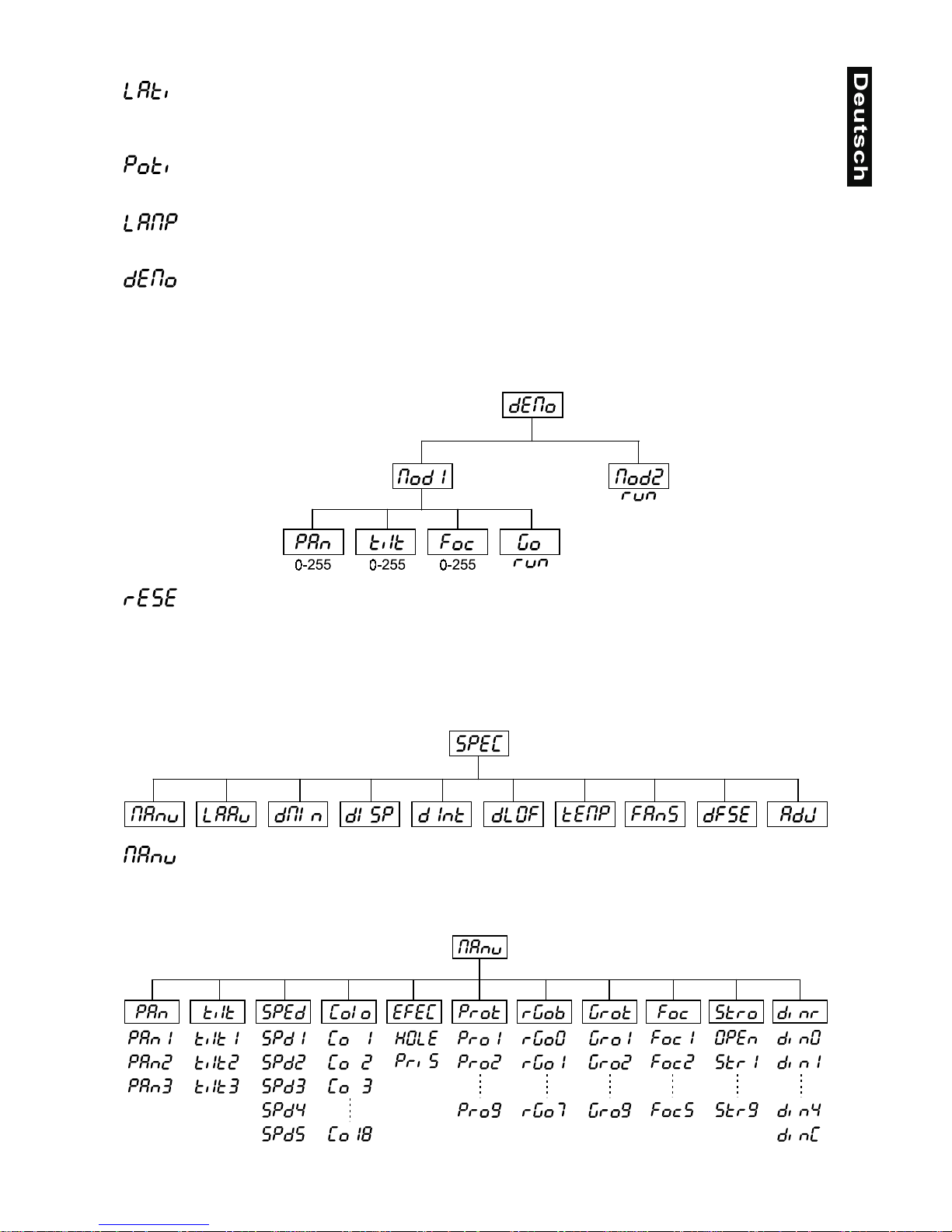
- Demonstrationsprogramm
Mit dieser Funktion können Sie das Demonstrationsprogramm des Projektors aktivieren. So lassen sich
einige der Möglichkeiten des MH-660 ohne externen Controller vorführen. Drücken Sie die Up-/DownTasten, um die Seque nzen
„Mod1“
oder
„Mod2“
auszuwählen. Die Sequen zen unter
„Mod1“
eignen sich
besonders für Projek tionen an d er W and, Deck e oder auf dem Boden, oh ne dass der Kopf sic h be wegt. Die
Sequenzen unter
„Mod2“
zeigen alle Funktionen des Projektors und eignen sich des halb b esonders gut zur
Produktpräsentation.
- Reset aktivieren:
Drücken Sie die Enter-Taste, um den Reset zu aktivieren. Dadurch werden die Motoren neu justiert.
SPEC - Spezialfunktionen
Über die Up-/Down-Tas ten können Sie sich innerhalb des Me nüs be weg en und di e ge wüns chte Funktion mit
der Enter-Taste auswählen.
- manuelle Ansteuerung:
Mit dieser Funktion lässt sich der Projek tor manuell ansteuern. Drücken Sie die Up- /Down-Tasten, um die
gewünschte Funktion aus zuwählen. Drüc ken Sie di e Enter-Tas te zur Best ätigung oder die Mode- Taste, um
abzubrechen.
Page 21
21
- Automatische Lampenschaltung
Mit dieser Funktion kann das Gerät so programmiert werden, dass die Lampe automatisch zündet, so bald
Sie das Gerät einschal ten. Wenn die Lampe automatisch ge zündet werden soll, wählen Sie über d ie Up/Down-Tasten
"ON"
aus oder
"OFF"
, wenn die Lampe aus ges cha lte t s ei n sol l. Drüc ken Sie die Enter -Taste,
um die Auswahl zu bestätigen oder die Mode-Taste, um diesen Modus zu verlassen.
- DMX-Werte:
Anzeige der aktuellen DMX -Werte jedes Kanals. Drück en Sie die Up-/Down-Tasten, um den gewünschten
Kanal auszuwählen. Drücken Sie die Enter-Taste um den Wert abzulesen oder die Mode-Taste, um
abzubrechen.
- Automatische Displayabschaltung:
Mit dieser Funktion lässt sich einste llen, dass das G erät das Displa y nach 2 Min uten au tomatisc h abschaltet
wenn keine Taste mehr gedrückt wurde. Drücken Sie die Up-/Down-Tasten, um
„ON“
oder
„OFF“
einzustellen. Drücken Sie die Enter-Taste zur Bestätigung oder die Mode-Taste, um abzubrechen.
- Displaybeleuchtung:
Mit dieser Funktion könne n Sie di e Dis p laybeleuchtung zwischen 20 u nd 100 ei ns tel len. Dr üc ken Sie die Up/Down-Tasten, um den Grad der Displaybeleuchtung einzustellen. Drücken Sie die Enter-Taste zur
Bestätigung oder die Mode-Taste, um abzubrechen.
- Lampe über DMX abschalten:
Mit dieser Funktion lässt sich die Lampenschaltung über DMX deaktivieren. Drücken Sie die Up-/DownTasten, um
„ON“
(Lampe über DMX abschalten) oder
„OFF“
(Lampe nicht über DMX abschalten)
einzustellen. Drücken Sie die Enter-Taste zur Bestätigung oder die Mode-Taste, um abzubrechen.
- Temperatur
Temperaturangabe im Inneren des Projek tors in Grad Celsius. Die n ormale Betriebstem peratur sollte unter
70° C liegen. 70° Innentemperatur und mehr sind bereits als kritisch zu bewerten und führen zur
Abschaltung der Lampe. Bitte beachten Sie, dass die Umgebungstemperatur niemals über 45° C liegen
sollte, damit eine ausreichende Kühlung gewährleistet ist.
- Regelung der Lüftergeschwindigkeit
Mit dieser Funktion lässt sich die Lüftergeschwindigkeit über vier verschiedene Modi regeln. Mit den Up/Down-Tasten können S ie den gewünsc hten Mo dus
„High, reG, Lo.HI, Lo.OF“
auswählen. Drücken Sie d ie
Enter-Taste zur Bestätigung oder die Mode-Taste, um abzubrechen.
- Lüftergeschwindigkeit maximal
Der Projektor wird mit maximaler Lüfterleistung gekühlt.
- automatische Anpassung der Lüftergeschwindigkeit
Ab einer gewissen Temperatur wird die Lüftergeschwindigkeit automatisch erhöht, um einen
Ausfall des Gerätes zu verhinder n. Diese Automatik k ann sich bis zu sieben Mal wiederholen,
bis die Innnentemperatur wieder ein unkritischen Niveau erreicht hat.
- Lüftergeschwindigkeit niedrig/maximal
Die Lüftergeschwind igkeit bleibt so lange niedrig, bis die Innentemperatur des Projek tors den
Maximalwert erreicht hat. Der Projektor schaltet dann automatisch auf maximale Lüfterleistung.
Page 22
22
- Lüftergeschwindigkeit niedrig/Lampenabschaltung
Die Lüftergeschwind igkeit bleibt so lange niedrig, bis die Innentemperatur des Projek tors den
Maximalwert überschritten wird. Der Projektor schaltet dann automatisch die Lampe ab.
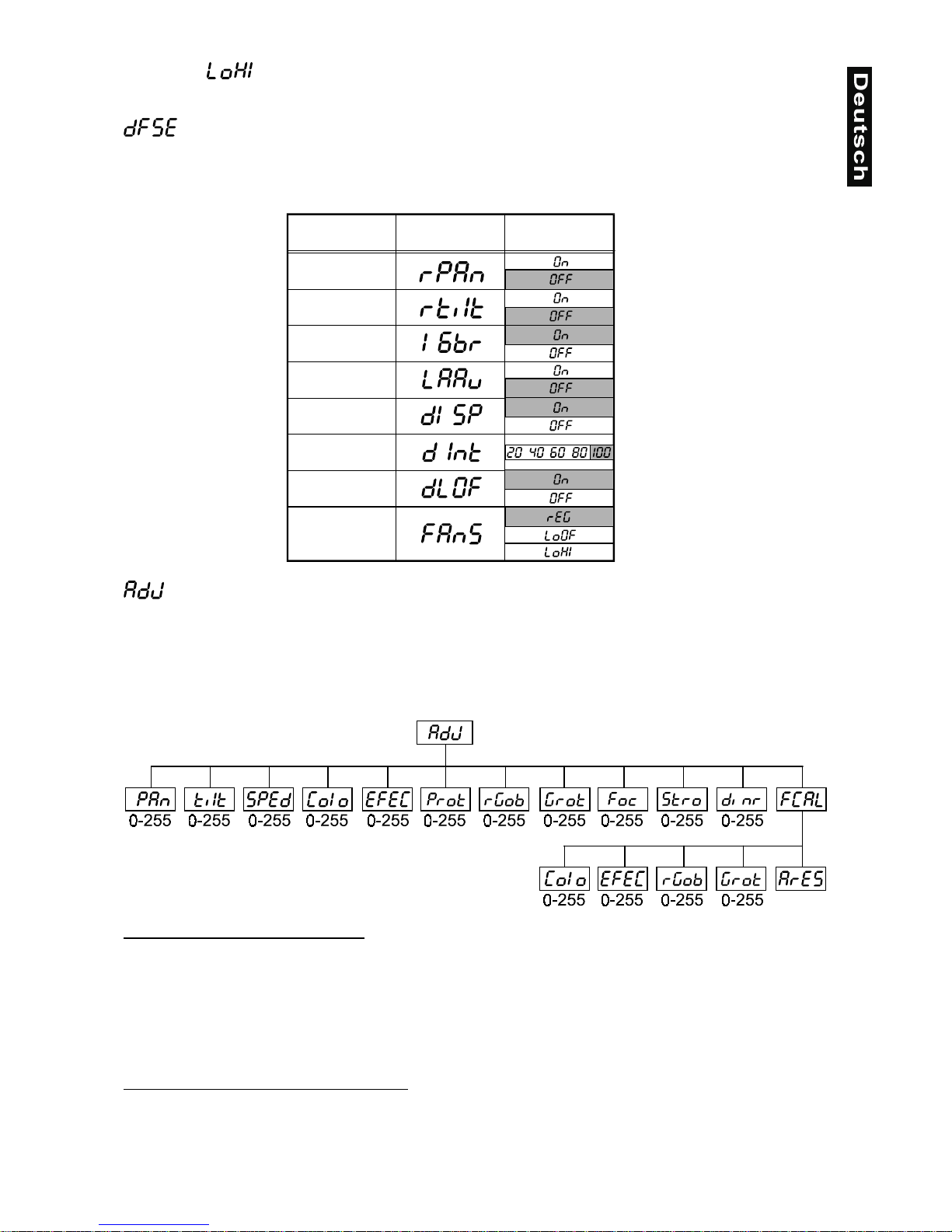
- Voreinstellungen
Mit dieser Funktion lassen sich alle Individualdaten des Projektors auf die Voreinstellungen ab Werk
zurücksetzen. Drück en Sie d ie E nter-T aste, um die Werte zurückzusetzen. Auf dem Displa y er schein t
“rSt”
.
Die einzelnen Voreinstellungen entnehmen Sie bitte unten stehender Tabelle.
- Einstellung der Ausgangspositionen:
Mit dieser Funktion lassen sich das Farb-, Gobo- und Prismenrad auf die korrekten Ausgangspositionen
kalibrieren. Drück en Sie die Up-/Down-T asten, um sich im Menü zu bewegen. Auf dem Display erschein en
von Schritt zu Schritt die Folgende n Funktionen:
„PAn, Tilt, SPEd, Colo, EF EC, Prot, rGOB, Grot, Foc,
Stro, dimr, FCAL“
über die Sie den Projek tor auf die gewü nschte Position ( 0-255) ei nstellen können, bevor
kalibriert wird. Sobald Sie die Posit ionen eingegeben haben, wähl en Sie die Letzte Funktion
„FCAL“,
und
das Gerät wird kalibriert.
1. Kalibrieren über das Control Board
Drücken Sie die Enter -Taste und auf dem Display erscheint durch Drücken der Up-/Down-Tasten:
„Colo,
EFEC, rGob, Grot“
für sehr weiche Funktionskalibrierung. Wählen Sie eine dieser Funktionen über die
Enter-Taste um den richtigen Wert zwischen 0 und 255 einzugstellen. Drücken Sie die Enter-Taste zur
Bestätigung oder die Mode-Taste um abzubrechen. Diese Vorgehensweise lässt sich für jeden
Kalibrierungsparameter wiederholen. Sobald die Kalibrierungseinstellungen vorgenommen sind, muss die
Funktion
„ArES“
gewählt werden, um die eingestellten Werte in das EEPROM zu übertragen und einen
Reset auszuführen. Sobald der Reset a bgesch lossen is t, erschei nt auf dem Display „ FCAL. Drück en Sie d ie
Enter-Taste, um die Kalibrierung zu wiederholen oder die Mode-Taste, um zum „AdJ“ Menü zurückzukehren.
2. Kalibrierung über den externen Controller
Drücken Sie die Enter -Taste und auf dem Display erscheint durch Drücken der Up-/Down-Tasten:
„Colo,
EFEC, rGob, Grot“
für sehr weiche Funktionskalibrierung. Wählen Sie eine dieser Funktionen über die
Enter-Taste aus. Jetzt können Sie die verschiedenen Räder über Ihren Controller kalibrieren. Das
Kalibrierungsprotokoll finden Sie unten stehend.
Eigenschaft Display Vorgabewert
(Unterlegt)
Pan reverse
Tilt reverse
Auflösung
Autom. Lam-
penschaltung
Automat.
Displayabsch
Displaybe-
leuchtung
DMX-
Lampensch.
Lüfterleist.
Page 23
23
DMX Kalibrierungsprotokoll:
XMD
lennahC
123 4 5678
noitcnuF.LOC- .CEFEBOGRTORG- SRUOLOC-
NOITARBILAC
552-0
-
NOITARBILAC
552-0
NOITARBILAC
552-0
NOITARBILAC
552-0
-
DRADNATS
LOCOTORP
-
TNEMEVOMPETSORCIMHTOOMS
901112131415161
TCEFFE
)MSIRP(
MSIRP
NOITATOR
GNITATOR
SOBOG
OBOG
NOITATOR
-SUCOFOBORTSREMMID
DRADNATS
LOCOTORP
DRADNATS
LOCOTORP
DRADNATS
LOCOTORP
DRADNATS
LOCOTORP
-
DRADNATS
LOCOTORP
DRADNATS
LOCOTORP
DRADNATS
LOCOTORP
Nachdem Sie die benötigt en Funktionen k alibriert haben und mit der Enter -Taste bestätigt haben, mus s die
Funktion
„ArES“
gewählt werden, um die eingestellten Werte in das EEPROM zu übertragen und einen
Reset auszuführen.
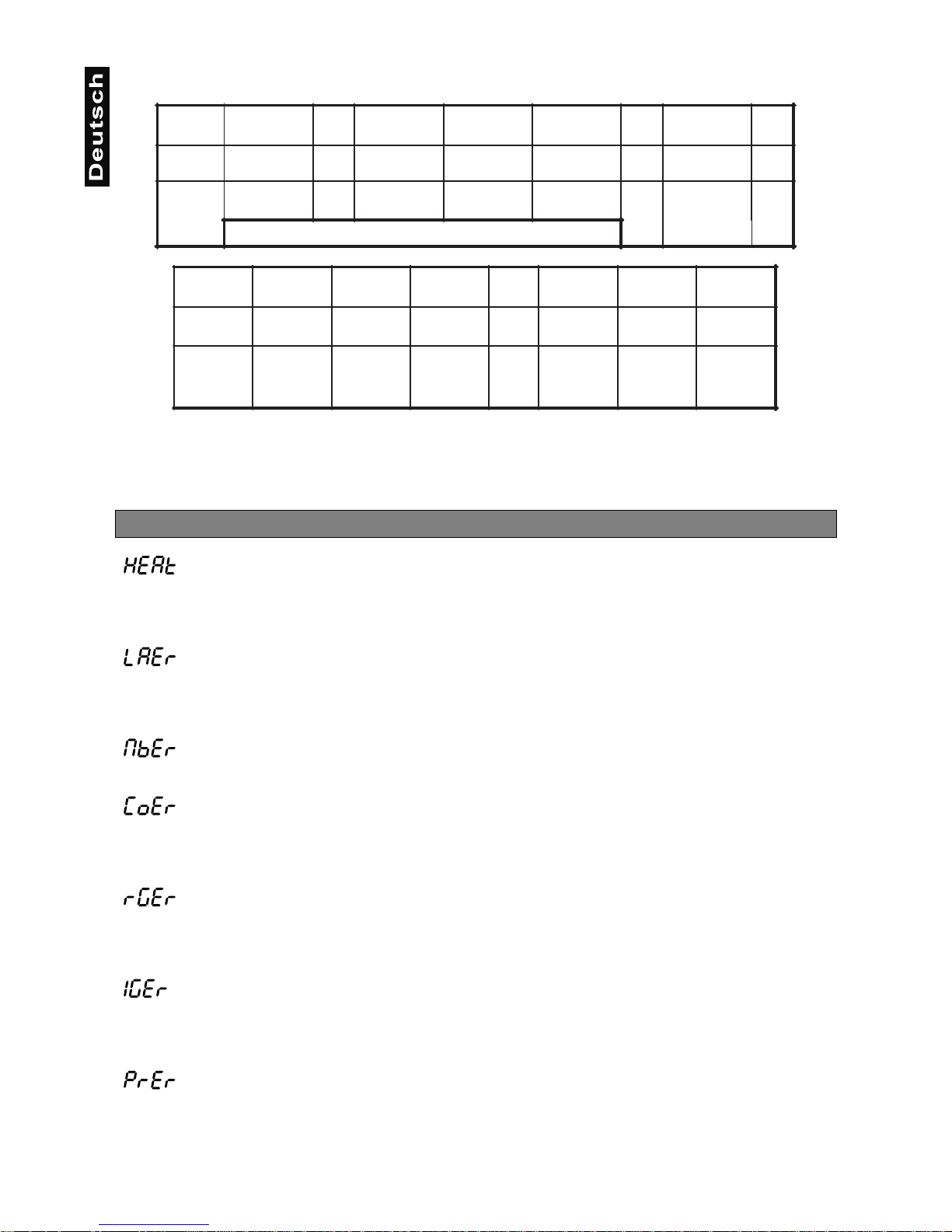
Fehlermeldungen
Diese Fehlermeldung ersc heint, wenn Sie versuchen, die Lampe zu zünden bevor die 5 Minute n Abkühlzeit
verstrichen sind. Die Meldung ersc heint, wenn die Lampe nach 20 S ekunden nicht gezündet ha t. Der MH660 speichert die Information wenn Si e vorzeitig versuchen, die Lampe zu zünd en, und zündet die Lampe
automatisch nachdem die 5 Minuten verstrichen sind.
Nach 7 fehlerhaften Vers uchen, die Lampe zu zün den, erscheint auf dem Display
„LAEr“
. Dies bedeutet,
dass die Lampe beschädigt ist oder gar keine Lampe installiert ist oder ein interner Fehler vorliegt.
Bitte setzen Sie eine Lampe ein oder ers etzen Sie die defekte Lam pe. Sollte ein interner Feh ler vorliegen,
setzen Sie sich bitte mit Ihrem Fachhändler in Verbindung.
Diese Fehlermeldung ersc heint, wenn die Komm unikation zwisc hen Hauptplati ne und Control Board gestört
ist.
Fehler am Farbrad. Diese Fehlermeldung erscheint, wenn nach dem Reset magnetisch-indizierte
Fehlfunktionen vorl iegen (Photodiode def ekt oder der Magnet fehlt) oder der Steppermotor def ekt ist (oder
dessen Treiber auf der Hauptplatine). Dabei befindet sich das Farbrad nach dem Reset nicht in der
Vorgabeposition.
Fehler am rotierenden Goborad. Diese Fehlermeldung erscheint, wenn nach dem Reset magnetischindizierte Fehlfunk tionen vorliegen (P hotodiode defekt oder der Magnet fehlt) o der der Stepperm otor defekt
ist (oder dessen Treiber auf der Hauptplatine). Dabei befindet sich das rotierenden Goborad nach dem Reset
nicht in der Vorgabeposition.
Indexfehler am rotierenden Gobo. Diese Fehlermeldung erscheint, wenn nach dem Reset magnetischindizierte Fehlfunk tionen vorliegen (P hotodiode defekt oder der Magnet fehlt) o der der Stepperm otor defekt
ist (oder dessen Tr eiber auf der Hauptplatine). Dabei bef indet sich das rotierende Gobo nach dem Reset
nicht in der Vorgabeposition.
Fehler am Prismenrad. Diese Fehlermeldung erscheint, wenn nach dem Reset magnetisch-indizierte
Fehlfunktionen vorl iegen (Photodiode def ekt oder der Magnet fehlt) oder der Steppermotor def ekt ist (oder
dessen Treiber auf der Hauptplatine). Dabei befindet sich das Prismenrad nach dem Reset nicht in der
Vorgabeposition.
Page 24
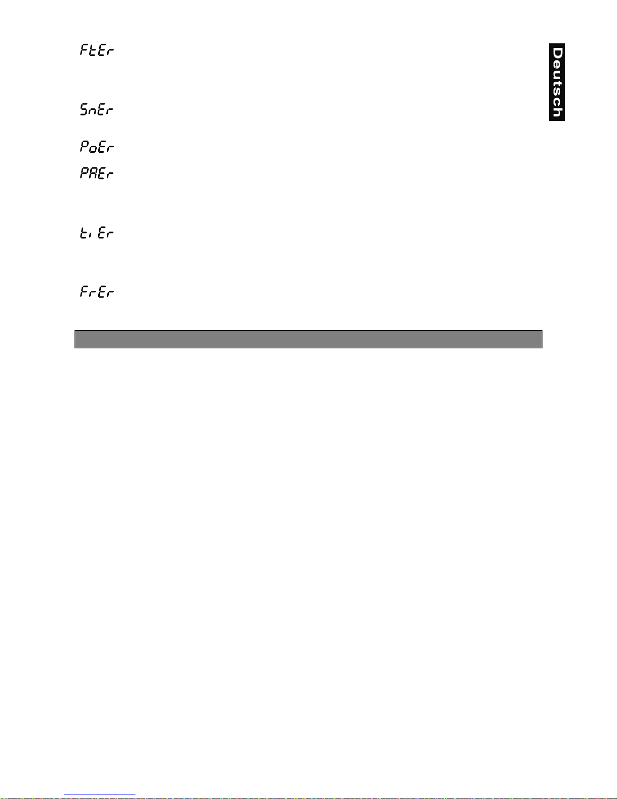
24
Diese Fehlermeldung bedeutet, dass das Gerät über hitzt ist (was bei 45° C oder mehr der Fall s ein kann)
und das Relais die Lampe abgeschaltet hat. Diese Meldung bleibt solan ge im Display, bis die Tem peratur
sich auf ein unkritisches Niveau gesenkt hat. Danach ersche int
„HEAt“
, um anzuzeigen, dass die Lampe
noch zu heiß ist.
Diese Fehlermeldung ersc heint, wenn die Photo diode defek t ist. Bitte setze n Sie sich m it ihrem Fachhänd ler
in Verbindung.
Diese Fehlermeldung erscheint, wenn das Gerät kurzzeitig vom Netz getrennt wurde.
Fehler an der PAN-Bewegung der Aufhängung. Diese Fehlermeldung erscheint, wenn nach dem Reset
magnetisch-indizierte Fehlfunktionen an der Aufhängung vorliegen (Photodiode defekt oder der Magnet
fehlt) oder der Steppermotor defek t ist (oder dessen Treiber auf der Hauptplatine) . Dabei befindet sich die
Aufhängung nach dem Reset nicht in der Vorgabeposition.
Fehler an der TILT-Bewegung d es Projektork opfes. Diese Fehlermeldu ng erscheint, wenn n ach dem Reset
magnetisch-indizierte Fehlfunktionen an dem Projektorkopf vorliegen (Photodiode defekt oder der Magnet
fehlt) oder der Steppermotor defek t ist (oder dessen Treiber auf der Hauptplatine). Dabe i befindet sich der
Projektorkopf nach dem Reset nicht in der Vorgabeposition.
Diese Fehlermeldung erscheint, wenn die Netzversorgung nicht auf 50 oder 60 Hz lautet.
Technische Daten
Spannungsversorgung
EU-Modell: 210/230/250 V AC, 50/60 Hz ~
US-Modell: 100/120/210/2 30/ 250 V AC, 50/6 0 Hz ~
Leistungsaufnahme: 400 W
Sicherung: T 3,15 A, 250 V
Lampe
MSD 230 V/250 W GY-9,5 oder MSD 230 V/200 W GY-9,5
Optisches System
- Parabolischer Spiegel für optimalen Lichtaustritt
- Doppelte Kondensorlinse mit hochwertigem Parabolspiegel
- 15° Standardobjektiv (optional 12° und 18°)
- Alle Linsen mit Antireflektionsbeschichtung
Farben
- 11 austauschbare dichroitische Filter plus weiß
- Farbwechsler mit einstellbarer Rotationsgeschwindigkeit
Gobos
Rotierende Gobos:
- 4 Metallgobos, 1 Glasgobo, 1 Dichro-Gobo
- Goboindizierung
- Ständige Rotation des Goborades
- Außendurchmesser 27 mm, Imagedurchmesser 23 mm
Strobe
- Strobe-Effekt mit variabler Geschwindigkeit (1 - 10 Blitze pro Sekunde)
Dimmer
Weicher Dimmer von 0 - 100 %.
Prisma
- Rotierendes 3-Facettenprisma bei verschiedenen Geschwindigkeiten in beide Richtungen rotierend.
Fokus
Motorischer Fokus zur Fokussierung von nah bis fern
Motor
- 10 hochwertige Steppermotoren (gesteuert durch Mikroprozessoren)
Page 25
25
Elektronik
- Digitaler Serieneingang DMX-512
-
14/16 Steuerkanäle (je nach Auflösung)
Steuerkanäle
Steuerkanal 1 - Drehbewegung (Pan)
Steuerkanal 2 - Kippbewegung (Tilt)
Steuerkanal 3 - Pan 16 Bit
Steuerkanal 4 - Tilt 16 Bit
Steuerkanal 5 - Pan / Tilt Geschwindigkeit
Steuerkanal 6 - Lampe, Reset, Lüfter
Steuerkanal 7 - Farben
Steuerkanal 8 - Ohne Funktion
Steuerkanal 9 - Prismenrad
Steuerkanal 10 - Rotierndes 3-fach Prisma
Steuerkanal 11 - Rotierende Gobos
Steuerkanal 12 - Indizieren der rotierenden Gobos, Goborotation
Steuerkanal 13 - Ohne Funktion
Steuerkanal 14 - Fokus
Steuerkanal 15 - Shutter, Strobe
Steuerkanal 16 - Dimmerintensität
Pan/Tilt
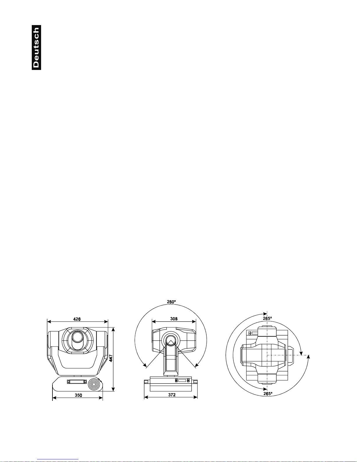
PAN-Bewegung innerhalb 530°
TILT-Bewegung innerhalb 280 °
8/16 Bit Auflösung der Pan/Tilt-Bewegung
Automatische Korrektur der Pan/Tilt-Position
Max. Schwenkbewegung (PAN) 530° in 2,65 s
Max. Kippbewegung (TILT) 280° in 1,68 s
Montage
Steht direkt auf dem Boden
Kann über zwei geeignete Haken horizontal oder vertikal montiert werden
Befestigungspunkte für Sicherheitsfangseil
Temperaturentwicklung
Maximale Umgebungstemperatur
t
a
: 45° C
Maximale Leuchtentemperatur im Beharrungszustand
t
B
: 80° C
Maße und Gewicht
Länge der Grundfläche (mit Griffen): 372 mm
Breite der Aufhängung: 426 mm
Höhe (Kopf horizontal): 447 mm
Gewicht (netto):16 kg
Gewicht (brutto): 25 kg
Page 26
26
Reinigung und Wartung
Der Unternehmer hat daf ür zu sorgen, dass sic herheitstechnische un d maschinentechnisc he Einrichtungen
mindestens alle vier Jahre durch einen Sachverständigen im Umfang der Abnahmeprüfung geprüft werden.
Der Unternehmer hat daf ür zu sorgen, dass sic herheitstechnische un d maschinentechnisc he Einrichtungen
mindestens einmal jährlich durch einen Sachkundigen geprüft werden.
Dabei muss unter anderem auf folgende Punkte besonders geachtet werden:
1) Alle Schrauben, mit denen das Gerät oder Ger ät ete ile montiert sind, m üs sen fest sitzen und dür f en n ic ht
korrodiert sein.
2) An Gehäuse, Befestigun gen un d Mont ageor t (Deck e, Abh ängung, Tr averse) dürfen k eine Ver for m ungen
sichtbar sein.
3) Mechanisch bewegte Teile wie Achsen, Ösen u. Ä. dürfen keinerlei Verschleißspuren zeigen (z.B.
Materialabrieb oder Beschäd ig ung en) und dür f en sich nic ht un wuc htig dreh en.
4) Die elektrischen Anschlussleitungen dürfen keinerlei Beschädigungen, Materialalterung (z.B. poröse
Leitungen) oder Ablagerungen aufweisen. Weitere, auf den jeweiligen Einsatzort und die Nutzung
abgestimmte Vorschriften werden vom sachkundigen Installateur beachtet und Sicherheitsmängel
behoben.
Vor Wartungsarbeiten unbedingt allpolig vom Netz trennen!
LEBENSGEFAHR!
Es ist unbedingt erforderlich, dass Sie den Projektor in regelmäßigen Abständen reinigen, da der sich
ablagernde Schmutz und Staub sowie Nebelfluidrückstände die Leuchtkraft des Gerätes erheblich
beeinträchtigen.
Falls Sie das Gerät nicht reinigen, wird außerdem die Lebensdauer Ihres Gerätes beträchtlich verkürzt.
Verwenden Sie zur Reinigung ein fusselfreies, angefeuchtetes Tuch. Auf keinen Fall Alkohol oder
irgendwelche Lösungsmittel zur Reinigung verwenden!
Der Ablenkspiegel und die Objektivlinse sollten wöchentlich gereinigt werden, da sich sehr schnell
Nebelfluidrücks tände absetzen, die die Le uchtkraft des Gerätes er heblich reduzieren. De n Lüfter m onatlich
reinigen.
Die Gobos können mit einer weichen Bürste gereinigt werden. Reinigen Sie das Innere des Projektors
mindestens einmal im Jahr einem Staubsauger oder einer Luftbürste.
Die dichroitischen Farbfilter, das Goborad und die Innenlinsen sollten monatlich gereinigt werden.
Damit die Lager der rot ierenden Teile gut funk tionieren, müssen sie ca. a lle 6 Monate geschmiert werden.
Zum Ölen ist eine Spritze mit einer feinen Nadel zu benutzen. Die Ölmenge darf nicht übermäßig sein, um zu
vermeiden, dass das Öl während des Rotierens ausläuft.
Im Geräteinneren bef inden sich außer der Lampe und der Sicherung k eine zu wartenden Teile. W artungsund Servicearbeiten sind ausschließlich dem autorisierten Fachhandel vorbehalten!
Bitte beachten Sie auch die Hinweise unter "Lampeninstallation/Lampenwechsel".
Sicherungswechsel
Wenn die Feinsicher ung des Gerätes def ekt ist, darf diese nur dur ch eine Sicherung gleichen Typs er setzt
werden.
Vor dem Sicherungswechsel ist das Gerät allpolig von der Netzspannung zu trennen (Netzstecker
ziehen).
Page 27

27
Vorgehensweise:
Schritt 1:
Drehen Sie den Sicherungshalter an der Geräterückseite mit einem passenden Schraubendre-
her aus dem Gehäuse (gegen den Uhrzeigersinn).
Schritt 2:
Entfernen Sie die defekte Sicherung aus dem Sicherungshalter.
Schritt 3:
Setzen Sie die neue Sicherung in den Sicherungshalter ein.
Schritt 4:
Setzen Sie den Sicherungshalter wieder im Gehäuse ein und drehen Sie ihn fest.
Sollten einmal Ersatzteile benötigt werden, verwenden Sie bitte nur Originalersatzteile.
Wenn die Anschlussleitung dieses Gerätes beschädigt wird (festverbundene Anschlussleitung), muss sie
durch den autorisierten Fachhand el er s et zt werden, um Gefährdungen zu vermeiden.
Wenn die Anschlussleitung dieses Gerätes beschädigt wird (austauschbare Anschlussleitung), muss sie
durch eine besondere Anschlus s le itun g ersetzt werden, die von Ihrem Fachhändler erhä ltl ich is t.
Sollten Sie noch weitere Fragen haben, steht Ihnen Ihr Fachhändler jederzeit gerne zur Verfügung.
Anhang
Wir wünschen Ihnen m it Ihrem FUTURELIGHT MH-660 viel Spaß. W enn Sie sich an die Anweisungen d er
vorliegenden Bedienungsanleitung halten, versichern wir Ihnen, dass Ihnen das Gerät lange viel Freude
bereiten wird.
Sollten Sie noch Fragen haben, steht Ihnen Ihr Fachhändler gerne zur Verfügung.
Alle Rechte einschließlich Übersetzung vorbehalten. Kein Teil dieser Bedienungsanleitung darf ohne
schriftliche Genehmigung des Herausgebers reproduziert oder verändert werden.
Bitte beachten Sie: Technische Änderungen ohne vorherige Ankündigung und Irrtum vorbehalten.
7/00 ©
Page 28

28
0+6SRWOLJKW
8VHUPDQXDO
Table of contents
Introduction......................................................................................................................29
Features ........................................................................................................................29
Beampath......................................................................................................................2 9
Description of the fixture................................................................................................30
Safety................................................................................................................................ 31
Safety instructions.........................................................................................................31
Operating determinations ..............................................................................................31
Installation........................................................................................................................32
Fitting/Exchanging the lamp ..........................................................................................32
Installation of an optional lens .......................................................................................34
Inserting/Exchanging gobos..........................................................................................35
DMX-512 connection / connection between fixtur es......................................................38
DMX-Protocol...................................................................................................................39
Function of the control channels - 16 bit protocol..........................................................39
Function of the control channels - 8 bit protocol: ...........................................................41
Addressing.......................................................................................................................41
Remotely controllable functions ....................................................................................42
Lamp..............................................................................................................................42
Switching on and off the lamp via the Control Board.....................................................42
Colour-wheel..................................................................................................................42
Rotating gobo-wheel......................................................................................................42
3-facet rotating prism.....................................................................................................42
Focus.............................................................................................................................42
Dimmer / Shutter / Strobe..............................................................................................42
Fan ................................................................................................................................43
Control Board...................................................................................................................43
Main functions ...............................................................................................................43
SPEC -Special functions................................................................................................44
Error and information messages....................................................................................47
Technical specifications .................................................................................................48
Cleaning and maintenance .............................................................................................50
Appendix...........................................................................................................................51
Page 29
29
CAUTION!
Keep this device away from rain and moisture!
Unplug mains lead before opening the housing!
FOR YOUR OWN SAFETY, PLEASE READ THIS USER MANUAL CAREFULLY
BEFORE YOU INITIAL START - UP!
Introduction
Thank you for having ch osen a FUTURELIGHT MH-660 . You acquired a versati le, powerful and intellig ent
lighting-effect.
Unpack your FUTURELIGHT MH-660 and mak e sure that there are no damages c aused by transpor tation.
Should there be any, please consult your local dealer and do not take the device into operation.
Features
Moving-head spot
Rotating gobo-wheel with 6 interchangeable and indexable rotating gobos plus open. Rotating gobos: 4
metal gobos, 1 multicolor dichroic gobo, 1 glass gobo. Rotating gobo-wheel continuous rotation • The
rotating gobos can b e turned by 360°, the a djusted positio n is memorized • 3 additional metal-gob os and 2
glass-gobos are incl uded • Colo ur-wheel with 11 dichroic filters plus o pen. Co lour-wheel continuous rotation
(rainbow effect) in both directions • Via the c om bination between dichro- gob os and color-whe el or m ultico lordichro-gobo even more colour-combinations possible • Rainbow-effect in both directions • High-speed
rotating 3-facet prism • Rem otely controllabl e motorized f ocus • Combined shutter/dim mer unit a llowing ver y
smooth dimming and str obo effec t 1-10 flash per sec . • Modular construction of fixture • Ad dressing, s pecial
functions setting, effects calibration via control panel with 4-digit LED display • Readout fixture and lamp
usage, receiving DMX values, temperature, etc • Built-in analyzer for easy fault find ing, error messages •
Remotely switching of th e lamp • Built-in demo sequences • Pr eprogrammed variable/random strobe and
dimmer pulse-eff ects • Macro-function for rotat ing gobos/rot ating prism combinations • Bl ack- out while Head
moving or gobo/colour/prism changing • Remotely controllable speed of Pan/Tilt movement for easy
programming • Remote r eset f unctio n • Inte llige nt contr ol pan el with 4-dig it L ED disp la y • Sil ent fans cool ing;
remotely controllable speed of fans • 16 DMX-channels - 16 bit Pan/Tilt movement resolution • 14 DMXchannels - 8 bit Pan/Tilt movement resolution • Pan-movement range 530° • Tilt-movement range 280° • 8/16
bit movement resolu tion • Automatic Pan/T ilt position correction • H igh luminous-ef ficiency parabolic m irror
and double condenser system • 15° standard objective (1 2° and 18° optio nal) • All lens es are anti-ref lection
coated • 10 high-qualit y step per-m otors for smooth m ovem ents • Self-r esetable th erm o- fuse • F or MSD/HSD
230 V/250 W GY-9.5 or MSD/HSD 230 V/200 W GY-9.5 lamp • DMX-control via every standard DMXcontroller • Suitable FUTURELIGHT controllers: CP-192 controller
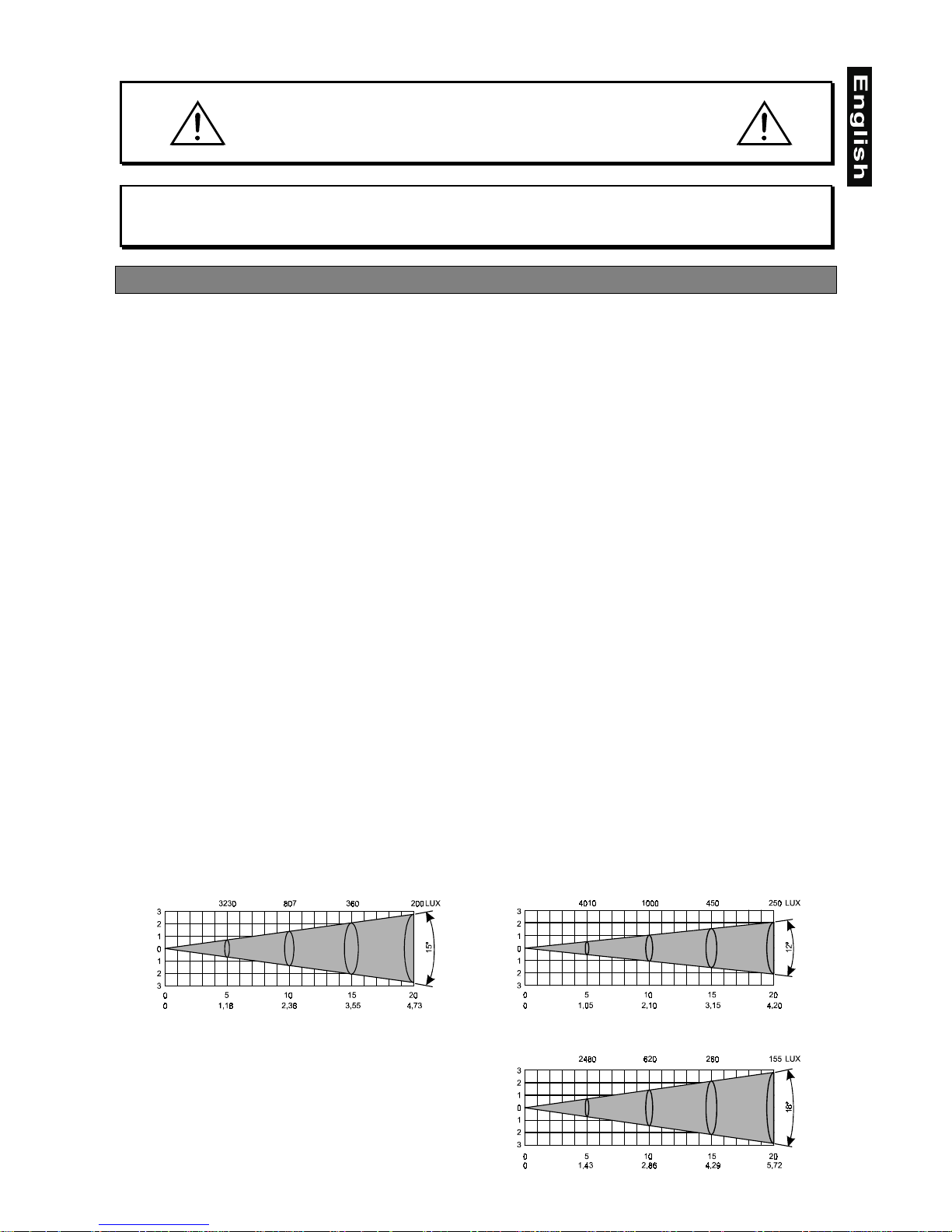
Beampath
Standard 15° objective Optional narrow 12°objective
Beam opening (m)Beam opening (m)
Optional wide 18°objective
Beam opening (m)
Page 30
30
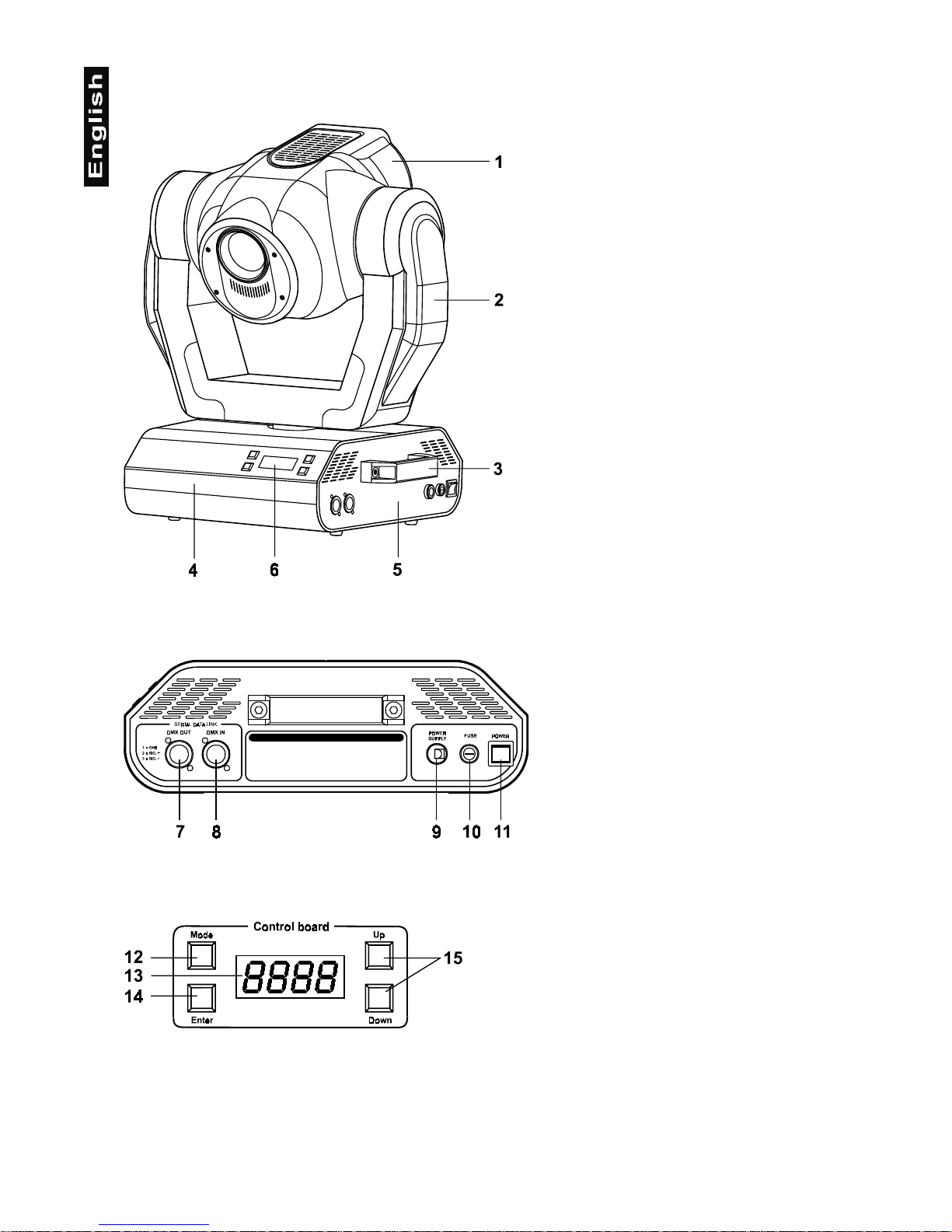
Description of the fixture
1
- Projector-head
2
- Yoke
3
- Carring handles
4
- Base
5
- Base - side panel
6
- Control Board
Base - side panel:
7
- DMX-output
8
- DMX-input
9
- Powercord
10
- Fuseholder
11
- Power-switch
Control Board:
12
- Mode-button
13
- Display
14
- Enter-button
15
- Up/Down-buttons
Page 31

31
Safety
Safety instructions
CAUTION!
Be careful with your operations. With a dangerous voltage you can suffer a dangerous
electric shock when touching the wires!
This device has left our prem ises in absolutely perfect c ondition. In order to m aintain this condition and to
ensure a safe operatio n, it is absol utely necessar y for the user to f ollow the safet y instructions and warning
notes written in this user manual.
Important:
Damages caused by the disregard of this user manual ar e not subj ect to war ranty. The d ealer
will not accept liability for any resulting defects or problems.
If the device has been exposed to dras tic temperature fluctuation (e.g. after transportation), do not switch it
on immediately. The arisi ng condensation water might d amage your device. Leave t he device switched off
until it has reached room temperature.
This device falls under protection-class I. The power plug must only be plugged into a protection class I
outlet.
Never let the power-c ord come into contact with other cabl es! Handle the power-cord and all connections
with the mains with particular caution!
Make sure that the available voltage is not higher than stated on the rear panel.
Make sure that the power -cord is never crimped or damaged b y sharp edges. Chec k the device and the
power-cord from time to time.
Always disconnect from the mains, when the device is not in use or before cleaning it. Only handle the
power-cord by the plug. Never pull out the plug by tugging the power-cord.
During the initial s tar t- up some smoke or sm ell may arise. This is a n or mal process and d oes no t necessarily
mean that the device is defective.
Caution:
During the operation, the housing becomes very hot.
Do not switch the device on and off in short intervals as this would reduce the lamp’s life.
HEALTH HAZARD!
Never look directly into the light source, as sensitive persons may suffer an
epileptic shock (especially meant for epileptics)!
Please consider that damages caused by manual modifications to the device are not subject to warranty.
Keep away children and amateurs!
Operating determinations
This device is a moving-head sp ot for cr eati ng decor at iv e ef f ec ts . This product is only allo wed to be o per at ed
with an alternating current of 230 V, 50 Hz and was designed for indoor use only.
This device is designed for professional use, e.g. on stages, in discotheques, theatres etc.
Lighting effects are not designed for permanent op eration. Consistent operation breaks will ensure that the
device will serve you for a long time without defects.
Page 32

32
Never run the device without lamp!
Do not shake the device. Avoid brute force when installing or operating the device.
Never lift the fixture by holding it at the projec tor-head, as the m echanics may be dam aged. Al ways hold t he
fixture at the transport handles.
When choosing the installation-spot, please make sure that the device is not exposed to extreme heat,
moisture or dust. Ther e should not be any cables l ying around. You endanger your own and the safety of
others!
The minimum distance between light-output and the illuminated surface must be more than 1 meter.
Make sure that the area below the installation place is blocked when rigging, derigging or servicing the
fixture.
Always fix the fixture with an appropriate safety-rope. Fix the safety-rope at the correct holes only.
Only operate the fixture after having checked that the housing is firmly closed and all screws are tightly
fastened.
The lamp must never be ignited if the objecti ve-lens or a ny housin g-cover is open, as d ischarge lam ps m ay
explose and emit a high ultraviolet radiation, which may cause burns.
The maximum ambient temperature
t
a
must never be exceeded.
CAUTION!
The lens has to be replaced when it is obviously damaged,
so that its function is impaired, e. g. due to cracks or deep scratches!
Operate the device only after havi ng familiarized with its functions. Do not perm it operation by persons not
qualified for operating the device. Most damages are the result of unprofessional operation!
CAUTION!
The lamp has to be replaced when it is damaged
or deformed due to the heat!
Please use the original packaging if the device is to be transported.
Please consider that unauthorized modifications on the device are forbidden due to safety reasons!
Never remove the serial barcode from the device as this would make the guarantee void.
If this device will be operated in an y wa y dif f erent to the one described in th is manual, the product m a y suff er
damages and the guarantee becomes void. Furthermore, any other operation may lead to dangers like shortcircuit, burns, electric shock, lamp explosion, crash etc.
Installation
Fitting/Exchanging the lamp
DANGER!
Install the lamp with the device switched off only.
Unplug from mains before!
Page 33

33
To insert the lamp MSD 230 V/250 W or MSD 230 V/200 W open the top cover of the head (see the
drawings to identify which cov er is top) by loosening the 4 Phillips screws on the f ront and rear s ides of the
top cover.
Then open the small lamp cover by loosening the 3 fastening screws (see the drawing).
If changing the lam p, remove the old lamp from the socket. Insert
the lamp to the socket.
Do not install a lamp with a higher wattage! A lamp like this
generates temperatures the device is not designed for.
Damages caused by non-observance are not subject to warranty.
Please follow the lamp manufacturer‘s notes!
Do not touch the glass-bulb bare-handed during the installation!
Make sure that the lamp is installed tightly into the lampholder
system.
Adjust the optimal dis tance 1-1.5 mm from the lens by turning the
screw
"A"
(see the drawings "Lamp adjustment" below).
Then close the small lamp cover by tighten 3 fastening screws
again.
Reclose the top cover of the head and tighten the 4 Phillips screws.
Before striking the la mp, reset the "LAti" co unter in the main m enu
of the Control Board, by pressing the "Up" and "Down" buttons in
one time and then confirming with the Enter-button.
Do not operate the fixture with opened housing-cover!
Bottom cover
Bottom cover
Top cover
2 Phillips screws2 Phillips screws
3 fastening screws
Lamp
Lamp cover
Page 34

34
Lamp adjustment
The MH-660 lampholder is aligned at the factor y. Due to differences between lamps, fine adjustm ent may
improve light performance.
Strike the lamp and focus the light on a flat surface ( wall). As the optim um distance of lamp f rom lens was
adjusted during the installing or chan ging the lamp (b y turning the scre w
"A"
), it is necess ary to adjust on ly
the second position by turning the screw "B", in order to center the hot-spot (the brightest part of the beam).
If the Hot Spot seems to be too bright, you can lower its intensit y by moving the lam p closer to the reflector.
Do so by turning srew
"A"
until the light is evenly distributed.
If the light on the edge s eems to be brighter as in th e center, the lamp is too cl ose at the reflector. In this
case, you need to m ove the lamp away from the reflector until the ligh t is evenly distr ibuted and the be am
appears bright enough.
Installation of an optional lens
The device is delivered with a 15°-standar d lens. If you wish to insert an optional 12° or 18°-lens, please
follow the instructions below:
Optional 12°-lens:
Remove the fixation-ring of the 15°-lens with an appropriate tool. Remove the lens. I nstall the optional 12°lens and fix it with the fixation-ring.
15°-lens Optional 12°-lens
"
"
Keep optimum distance to lens
-
CORRECT INCORRECT
"
"
Page 35

35
Optional 18°-lens:
Unscrew the knurled-hea d screw on the plate of the light-output. Insta ll the optional 18 °-lens and f ix it with
the knurled-head screw.
Inserting/Exchanging gobos
DANGER!
Install the gobos with the device switched off only.
Unplug from mains before!
To insert the gobos open the top c over of the he ad by loosening the 4 Phillips sc rews on the front and rear
sides of the top cover.
If you wish to use other f orms and patter ns as the st andard-gobos , or if gobos ar e to be exchanged, please
follow the instructions below:
Static gobo-wheel:
Carefully press the gobo out of the fixation. Make sure that you do not damage the clamps.
Rotating gobo-wheel:
CAUTION!
Never unscrew the screws of the rotating gobo
as the ball bearing will otherwise be opened!
Remove the fixation-ring with an appropriate tool. Remove the gobo and insert the new gobo. Press the
fixation-ring together and insert it in front of the gobo.
Page 36

36
Rigging
DANGER TO LIFE!
Please consider the EN 60598-2-17 and the respective national norms during the
installation! The installation must only be carried out by an authorized dealer!
The installation of the projector has t o be built a nd construct ed in a wa y that it can hold 1 0 times the wei ght
for 1 hour without any harming deformation.
The installation m ust always be secure d with a secondar y safety attachm ent, e.g. an appropriate catc h net.
This secondary safety attachment must be constructed in a way that no part of the installation can fall down if
the main attachment fails.
When rigging, derigg ing or servicing the f ixture staying in the ar ea below the ins tallation place, on bridges,
under high working places and other endangered areas is forbidden.
The operator has to m ake sure that safety-relating and machine-technical ins tallations are approved by an
expert before taking into operatio n for the first time and af ter changes before taking i nto operation another
time.
The operator has to m ake sure that safety-relating and machine-technical ins tallations are approved by an
expert after every four year in the course of an acceptance test.
The operator has to m ake sure that safety-relating and m achine-technical installations ar e approved by a
skilled person once a year.
Procedure:
The projector should be installed outside areas where persons may walk by or be seated.
IMPORTANT! OVERHEAD RIGGING REQUIRES EXTENSIVE EXP ERIENCE, including (but not limited to)
calculating working load limits, installation material being used, and periodic safety inspection of all
installation material and the proj ector. If you lack thes e qual ificatio ns, do not att em pt the i nstallat ion yourself ,
but instead use a professional structural rigger. Improper installation can result in bodily injury and.or
damage to property.
The projector has to be installed out of the reach of people.
If the projector shall be lowered from the ceiling or high joists, professional trussing systems have to be used.
The projector must never be fixed swinging freely in the room.
Caution:
Projectors may cause severe injuries when crashing down! If you have doubts concerning the
safety of a possible installation, do NOT install the projector!
Before rigging make sure that the insta llation area can h old a m inimum point load of 10 tim es the projec tor's
weight.
DANGER OF FIRE!
When installing the device, make sure there is no highly-inflammable
material (decoration articles, etc.) within a distance of min. 0.5 m.
CAUTION!
Use 2 appropriate clamps to rig the fixture on the truss.
Follow the instructions mentioned at the bottom of the base.
Make sure that the device is fixed properly! Ensure that
the structure (truss) to which you are attaching the fixtures is secure.
Page 37

37
The Moving-Head can b e p lace d d ir ectly on the
stage floor or rigged in any orientation on a
truss without altering its operation characteristics (see the drawing).
The fixture’s base enables to be mounted in
two ways. Use the clam ps with screws M10 or
M8 - check the base bottom.
For overhead use, alwa ys install a safety-ro pe
that can hold at least 10 times the weight of the
fixture. You must only use safety-ropes with
screw-on carabines. Pull the safety-rope
through the hole on the bottom of the base a nd
over the trussing s ystem etc. Insert the end in
the carabine and tighten the fixation screw.
Connection with the mains
Connect the device to the mains with the power-plug.
The occupation of the connection-cables is as follows:
Cable Pin International
Brown Live L
Blue Neutral N
Yellow/Green Earth
The earth has to be connected!
Safety-rope
Clamp
Page 38

38
In general, lighting effects should not be connected to dimming-packs.
DANGER TO LIFE!
Before taking into operation for the first time, the installation has to be approved by an expert!
DMX-512 connection / connection between fixtures
The wires must not come into contact with each other, otherwise
the fixtures will not work at all, or will not work properly.
Only use a stereo shielded cable and 3-pin XLR-p lugs and co nnectors in order t o connect th e controll er with
the fixture or one fixture with another.
Occupation of the XLR-connection:
If you are using the recommended FUTURELIGHT-controllers, you can connect the DMX-output of the
controller directly with the DMX-input of the first fixture in the DMX-chain. If you wish to connect DMXcontrollers with other XLR-outputs, you need to use adapter-cables.
Building a serial DMX-chain:
Connect the DMX-output of the first fix ture in the DMX-chain with the DMX-input of the next fixture. Al ways
connect one output with the input of the next fixture until all fixtures are connected.
Caution:
At the last fixture, the D MX-cable has to be ter minated with a ter minator. Solder a 120
Ω
resistor
between Signal (–) and Signal (+) into a 3-pin XLR-plug and plug it in the DMX-output of the last fixture.
Page 39

39
DMX-Protocol
Function of the control channels - 16 bit protocol
Channel 1 - Horizontal movement (Pan)
Push slider up in order to move head horizontally (PAN).
Gradual head adjustm ent from one end of the sl ider to the other (0-25 5,
128-center). The head can be turned by 530° and stopped at any
position you wish.
Channel 2 - Vertical movement (Tilt)
Push slider up in order to move head vertically (TILT).
Gradual head adjustm ent from one end of the sl ider to the other (0-25 5,
128-center). The head can be turned by 280° and stopped at any
position you wish.
Channel 3 - Pan fine 16 bit
Channel 4 - Tilt fine 16 bit
Channel 5 - Speed of PAN / TILT movement
0 Max speed (tracking mode)
1 Max speed (vector mode)
249 Min. speed (vector mode)
250-255 Max. speed, black-out while PAN,
TILT moving or color changes (tracking mode)
Channel 6 - Switch on / off the lamp, reset, speed control of cooling fan
0 Open, max. speed of fan
127 Open, min. speed of fan (silent operation) from 0 to 127
- decreasing speed of fan
128 - 139 Switch on the lamp, reset, open position
140 - 239 No function
230 - 239 Switch off the lamp after 3 seconds
240 - 255 No function
Page 40

40
Channel 7 - Colours
Linear colour change follo wing the m ovement of the slider. In th is way you can stop the c olour-wheel in any
position - also between two colours creating double-coloured beams.
Between 128 and 190 and between 193 and 255, the colour-wheel rotates continuously the so-called
"Rainbow" effect.
0 Open / white
10 Turquoise
21 Red
32 Cyan
42 Green
53 Magenta
64 Light Blue
74 Yellow
85 Green
96 Pink
106 Blue
117 Orange
128 - 190 Forwards rainbow effect from fast to slow
191 - 192 No rotation
193 - 255 Backwards rainbow effect from slow to fast
Channel 8 - No function
Channel 9 - Prism-wheel
0 - 95 Open position (hole)
96 - 159 3 - facet rotating prism
160 - 255 Prism/Gobo macros
160 - 167 Macro 1
168 - 175 Macro 2
176 - 183 Macro 3
184 - 191 Macro 4
192 - 199 Macro 5
200 - 207 Macro 6
208 - 215 Macro 7
216 - 223 Macro 8
224 - 231 Macro 9
232 - 239 Macro 10
240 - 247 Macro 11
248 - 255 Macro 12
Channel 10 - 3-facet-prism rotation control
0No rotation
1 - 126 Forwards rotation from fast to slow
127 - 128 No rotation
129 - 255 Backwards rotation from slow to fast
Channel 11 - Rotating gobos, cont. rotation
0 - 31 Open
32 - 63 Rot. gobo 1 (multicolor dichroic)
64 - 95 Rot. gobo 2 (glass)
96 - 127 Rot. gobo 3 (metal)
128 - 159 Rot. gobo 4 (metal)
160 - 191 Rot. gobo 5 (metal)
192 - 223 Rot. gobo 6 (metal)
224 - 255 Rot. gobo wheel cont. rotation slow to fast
Page 41

41
Channel 12 - Rotating gobo index, rotating gobo rotation
0 - 127 Gobo indexing
128 - 191 Forwards gobo rotation from fast to slow
192 No rotation
193 - 255 Backwards gobo rotation from slow to fast
Channel 13 - No function
Channel 14 - Focus
0 - 255 Continuous adjustment from far to near
Channel 15 - Shutter, Strobe
0 - 31 Shutter closed
32 - 63 No function (Shutter open)
64 - 95 Strobe-effect from slow to fast (max. 10 flashes/second)
96 - 127 No function (Shutter open)
128 - 159 Pulse-effect in sequences
160 - 191 No function (Shutter open)
192 - 223 Random strobe-effect from slow to fast
224 - 255 No function (Shutter open)
Channel 16 - Dimmer intensity
0 - 255 Gradual adjustment of the dimmer intensity from 0 to 100 %
Function of the control channels - 8 bit protocol:
XMD
lennahC
1234567 8 9 0111213141
noitcnuF
NAPTLIT
TLIT/NAP
DEEPS
NAF
FFO/NO
PMAL
SRUOLOC-MSIRP
MSIRP
NOITATOR
GNITATOR
SOBOG
OBOG
NOITATOR
-SUCOFOBORTSREMMID
Addressing
The Control Board on the top side of th e MH-660 allows you to assign the D MX fixture address, which is
defined as the first channel from which the MH-660 will respond to the controller.
If you set, for example, the address to channel 5, the MH-660 will use the channel 5 to 20 for control.
Please, be sure that you don’t hav e any ov erlapping c hannels in order to contro l each MH-660 correc tly and
independently from any other fixture on the DMX data link.
If two, three or more MH-660 are addressed similarly, they will work similarly.
For address setting follow this procedure:
1.
Switch on the MH-660 and wait until the fixture reset has finished (
"rSt"
is flashing at the display).
2.
Press the
[Mode]
key in order to access the main menu. Browse through the menu by pressing the [Up]
and [Down] ke ys until the disp lay shows
"A001"
. Confirm by pressing
[Enter]
key and the letter
"A"
wil l
flash.
3.
Use the [Up] and [Down] keys to select the desired address.
4.
Confirm by pressing
[Enter]
or
[Mode]
to cancel.
Controlling:
After having addressed all MH-660 , you may now start operating these via your lighting controller.
Note:
After switching on, t he MH-660 will autom aticall y detect whether DMX 512 data is receiv ed or not . If there is
Page 42

42
no data received at the DMX-input, the display will start to flash
"A001"
with actually set address.
This situation can occurr if:
- the 3 PIN XLR plug (cable with DMX signal from controller) is not connected with the input of the MH-660
- the controller is switched off or defective, if the cabl e or connec tor is def ective or the sign al wires ar e swap
in the input connector.
Note:
It’s necessary to insert the XLR term ination plug (with 120 Ohm) in the last lighting in the link in order to
ensure proper transmission on the DMX data link.
Remotely controllable functions
Lamp
The MH-660 is to be operated with a MSD 230 V/250 W GY-9.5 or MSD 230 V/200 W GY-9.5 lamp.
A relay inside of the MH-660 allo ws you to sw itch on and of f the lam p via the Control Board on the top sid e
or via your controller without affecting the rest of the lighting.
Switching on and off the lamp via the Control Board
1.
Switch on the MH-660 and wait until the fixture res et has finis he d.
2.
Press the
[Mode]
key in order to access the main menu. Browse through t he menu by press ing the [Up]
and
[Down] keys until the display shows
"LAMP"
. Confirm by pressing
[Enter]
key.
3.
Use the [Up] and [Down ] ke ys to sel ect
"On"
for switching on the l amp and
"Off"
for switch off the lamp
and press
[Enter]
to confirm or
[Mode]
to cancel.
Note :
It is also important to note that the dischar ge lam p is a cold r estrik e type, which m eans tha t it has t o be cold
before re-striking. F or this reason, you have to wait 5 minutes (max. speed of fan must be adjuste d) after
having switched off the lam p bef ore you can s witch it bac k on agai n. If you tr y to s witch on the lamp within 5
minutes after having s witched it off , the MH-660 will s tore this infor mation and autom atically ig nite the lamp
when the 5 minutes perio d has ex pire d. The message
"HEAt"
will appear on the co ntrol bo ard d ispla y at the
back side of the MH-660. If the ignition of the lamp is seve n times unsuc cessful, on the dis play will appear
"LA.Er"
, meaning that the lamp could be dam aged or even m iss ed, or there cou ld be a f ailure o n the ign itor
or ballast.
Colour-wheel
The MH-660 features a colour-whee l with 12 color positions - 11 of these with dic hroic colors and the last
one open. The wheel can be position ed between two adjacent colors in any position. It is also p ossible to
rotate the color-wheel continuously at different speeds - the so-called "Rainbow effect“ is created.
Rotating gobo-wheel
The rotating gobo-whee l i nc lu des 4 metal gobos, 1 glass gobo and 1 multicolor dichroic gob o r ota tin g i n b oth
directions, indexabl e, r ot atin g gob o wh ee l cont. rotation slow to fast. The multicolor d ichr o ic go bo (c ont ai ni ng
C,M,Y colors) can be com bined with the color-wheel espec ially with cyan, magenta and yellow colours in
order to obtain several different m ulticolor beams. The gobos have an outs ide diameter of 27 mm and an
image diameter of 23 mm.
3-facet rotating prism
3-facet prism rotating in both directions at different speeds.
Focus
Motorized focus enables the beam to be focused anywhere on stage.
Dimmer / Shutter / Strobe
Smooth 0 - 100 % dimming is provided by the combined mechanical dimmer / shutter unit. This unit may also
be used for strobe-effects (1 - 10 flashes per second)
Page 43

43
Fan
The MH-660 is cooled by three axial fans - one each i n th e pr ojec tor hea d a nd o ne i n t he bas e. T he s pe ed of
the fan (and of course the noise) can be continuously reduced if very quiet performance is required.
By the Control Board using the
"FAnS"
function you can choose 4 types of low fan speed operating:
1. "HIGH" -
high speed of the fans
The cooling fans work on max. speed (max. cooling).
2. "reG" - continuous controlling of the fan speed
The fan automatically raises its speed in order to control inside temperature of the lighting, if the
temperature inside increases about certain level (the low fan speed reduces the coo ling of the lighting).
This cycle can repeat several times until the temperature inside is on suitable level.
3. "Lo.OF" - low speed / Switch off the lamp
The fan keeps the adjusted lo w speed until the t emperature exc eeds max. inside tem p. then the MH-660
automatically switches of f the lamp.
4. "Lo.HI"- low/high speed of the fan operating
The fan keeps the adjusted low spee d unti l the t em peratur e exceeds m ax. inside tem p. of the fixt ure, then
the MH-660 automatically switches from low to high the fan speed.
Control Board
The Control Board situat ed on the top side of the MH-660 offers several features. You can simply set the
lighting address, read the number of lamp or unit hours, switch on and off the lamp, run demonstration
sequences, make a reset and also use special functions for manual control and service purposes.
The main menu is ac cessed by pressing the
[Mode]
key - press this one so m any times until the display
shows message
"A001"
(with actually stored address). Br owse through the m enu by the pressing [U p] and
[Down] keys - the display shows step b y step these m essages:
A001, rPAn, rTilt, 16br, Lati, Poti, LAMP,
dEMo, rESE, SPEC
. Press
[Enter]
if you wish to select one of them. The functions provided are described in
the following sections and the function hierarchy is shown below.
Main functions
- DMX 512 Address settings
The letter
"A"
flashes. Use the [Up] and [down] keys to select required address (001 - 496) and press
[Enter]
to confirm or
[Mode]
to cancel and return to the main menu.
- Pan reverse
This function allo ws you to invert the Pan-m ovement. Use the [Up] and [Down] k eys to select
"On"
if you
wish this feature or
"Off"
if you don’t wish this feature and press
[Enter]
to confirm or
[Mode]
to cancel and
return to the main menu.
- Tilt reverse
This function allo ws you to invert the Tilt-m ovement. Use the [Up] and [Do wn] keys to select
"On"
if you
wish this feature or
"Off"
if you don’t wish this feature and press
[Enter]
to confirm or
[Mode]
to cancel and
return to the main menu.
- Movement resolution
By this function you can adj us t th e d esir ed movement resolution 8 or 1 6 b it. Use the [Up] and [Down] keys to
select ‘On’ if you wish the 16bit high resolution or
"Off"
if you wish onl y 8 bit resoluti on and pr ess
[Enter]
to
confirm or
[Mode]
to cancel and return to the main menu.
Note:
If you adjust the 16 bit resolution the f ixture will occup y 16 DMX chan nels, if you adjus t the 8 bit resolution,
the fixture will be operated by only 14 DMX channels. Please, check the DMX protocol.
- Lamp On time
This option enables you to read the total number of hours that the lamp has been powered on. Pr ess
[Enter]
or
[Mode]
to return to the main menu. In order to reset the coun ter to 0, you have to hold th e Up- an d Do wn-
button and press the Enter-button.
- Power On time
By this option you can read the total number of hours that the MH-660 has been powered o n. Press
[Enter]
or
[Mode]
to return to the main menu.
- Switch on / off the lamp
Use the
[Up]
and
[Down]
keys to select
"On"
if you wish the switch on the lam p or
"Off"
if you wish sw itch
Page 44

44
off the lamp and press
[Enter]
to confirm or
[Mode]
to cancel and return to the main menu.
- Demo sequences
This function allo ws you to run a special demo-test sequences without an exter na l controller, which wil l s ho w
you some possibilities of using MH-660. Press
[Up]
and
[Down]
keys to select the
"Mod1"
or
"Mod2"
sequences. The
"Mod1"
is suitable for projections on the wall, ceilling or ground without any head-
movement, the
"Mod2"
uses all MH-660 funct ions and therefore is goo d for a complete introduction of the
fixture.
- Reset Function
Press
[Enter]
key to run reset. T his option enabl es the MH-660 to i ndex all effec ts (functions) and r eturn to
their standard positions.
SPEC -Special functions
Use the
[Up]
and
[Down]
keys to browse through the special functions and select the one by pressing
[Enter]
.
- Manual control of effects
This function allows you to control m anually the channel functions of the f ixture. Use the [Up] and [Down]
keys to select desired function an d press
[Enter]
to adjust the effec t or
[Mode]
to cancel and return to the
menu.
- Lamp On automatically
This function enables to switch on the l amp automatically after switching o n the fixture. Use the [Up] and
[Down] keys to select
„On”
if you wish to switch on the lamp automaticall y after switching on the f ixture or
„Off”
if you wish the lamp of f after s witching on t he fixture and press
[Enter]
to confirm or
[Mode]
to cancel
and return to the menu.
- DMX values
Readout DMX values of each channel received by the fixture. Use the
[Up]
and
[Down]
keys to select
desired channel and pr ess
[Enter]
to read its value com ing to the fixture or
[Mode]
to cancel and return to
the menu.
Page 45

45
- Automatic blackout of Display
This function allows you to keep the disp lay on or to turn off autom atically 2 minutes after last press ing any
key on the control b oar d. Use the
[Up]
and
[Down]
keys to select
"On"
if you wish to k eep the d ispla y on or
"Off"
if you wish to turn off automatically 2 minutes after l ast pressing any key on the Contro l Board and
press
[Enter]
to confirm or
[Mode]
to cancel and return to the menu.
- Display intensity
With this function, you can adjust the display-intensit y from 20 to 100. Use the
[Up]
and
[Down]
keys to
select the level of the display-intensity and pr ess
[Enter]
to confirm or
[Mode]
to cancel and return to the
menu.
- Lamp off via DMX
This function allo ws you to switch off the lamp by DMX. Use the
[Up]
and
[Down]
keys to select
"On"
if you
want to switch off the lam p by DMX or
"Off"
if you don’t want to switch off the lamp by DMX and press
[Enter]
to confirm or
[Mode]
to cancel and return to the menu.
- Temperature
Inside temperature rea douts of the f ixture in Cels ius. Inside temper atures belo w 70° C are not cr itical. 7 0° C
and more lead to the lam p being switche d off. Please note t hat the outside temperature s hould not exc eed
45° C.
- Fan speed operating
By using this function you ca n choose 4 types of fan speed operating. Browse through this menu by the
pressing
[Up]
and
[Down]
keys - the display shows step by step the following messages:
"HIGH, reG,
Lo.HI, Lo.OF"
. Press
[Enter]
if you wish to select one of them or
[Mode]
to cancel and return to the menu.
- high speed of the fans
The cooling fans work on max. speed (max. cooling).
- continuous controlling of the fan speed
The fan automatically raises its sp eed in order to control insi de tem peratur e of the light ing, if the
temperature inside increases about certain level ( the low fan speed redu ces the cooling of the
lighting). This cycle can repeat several times until the temperature inside is on a suitable level.
- low/high speed of the fan operating
The fan keeps the adjusted low speed until t he temperature exceeds m ax. inside temp. of the
fixture, then the MH-660 automatically switches from low to high fan-speed.
- low speed / switch off the lamp operating
The fan keeps the adjusted low speed until the tem perature ex ceeds m ax . insid e tem p. then th e
MH-660 automatically switches off the lamp.
Page 46

46
- Default settings
Press
[Enter]
to reset all fixture personalities (not the adjusting functions) to the default values. On the
display will appear
„rSt”
meaning that the fixtur e makes the reset. See t he table of personalit y setting and
their default positions.
- Adjusting the default positions of colour, gobo and effect wheels
By this function you can calibrate and adjust the colour, gobo and effect wheels to their standard/right
positions. Use the [Up] and [Down] ke ys to browse through t he adjustin g menu - the displa y shows st ep by
step these messages :
"PAn, Tilt, SPEd, Colo, EFEC, Prot , rGOB, Grot, Foc, St ro, dimr, FC AL"
by which
you can adjust the fixture to the required / desir ed p os it ion ( 0- 255) before the function calibrat io n. Then when
the positioning is finished use the last
"FCAL"
function (Fixture calibration).
1. Calibration via the control board
Press
[Enter]
and the
[Up]
and
[Down]
keys in order to display the following messages:
"Colo, EFEC,
rGob, Grot"
for very smooth f unction calibration. S elect one of them , press
[Enter]
and use the
[Up]
and
[Down]
keys in order to adjust their ri ght value from 0 to 255. T hen press
[Enter]
to confirm or
[Mode]
to
cancel and return to the menu. This can be repeated for each calibration parameter if it is required. When the
calibration is f inishe d , it is necessary to use the
"ArES"
function in order to write the calibrat ion v alues to the
memory (EEPROM) and t o make a reset i n order to check the ne wly adjusted positions of the colour , gobo
and effect wheels. When the reset of the fixture is finished, the display will show the
"FCAL"
message.
Press
[Enter]
to repeat the calibration or
[Mode]
to return to the
"AdJ"
menu.
2. Calibration via the external controller
Press
[Enter]
and the
[Up]
and
[Down]
keys in order to display the following messages:
"Colo, EFEC,
rGob, Grot"
- calibration parameters. Select one of them and press
[Enter]
.
Now you can calibrate the colour, gobo a nd effect whee l by your contro ller. The DMX cal ibration protoc ol is
described in the table mentioned below.
Personality Display Def ault va lues
(Shaded)
Pan reverse
Tilt reverse
Resolution
Lamp on
automatically
Display
blackout
Display
intensity
Lamp off via
DMX
Fan speed
Page 47

47
DMX Calibration protocol:
XMD
lennahC
123 4 5678
noitcnuF.LOC- .CEFEBOGRTORG- SRUOLOC-
NOITARBILAC
552-0
-
NOITARBILAC
552-0
NOITARBILAC
552-0
NOITARBILAC
552-0
-
DRADNATS
LOCOTORP
-
TNEMEVOMPETSORCIMHTOOMS
901112131415161
TCEFFE
)MSIRP(
MSIRP
NOITATOR
GNITATOR
SOBOG
OBOG
NOITATOR
-SUCOFOBORTSREMMID
DRADNATS
LOCOTORP
DRADNATS
LOCOTORP
DRADNATS
LOCOTORP
DRADNATS
LOCOTORP
-
DRADNATS
LOCOTORP
DRADNATS
LOCOTORP
DRADNATS
LOCOTORP
After having calibra ted required functions press
[Enter]
to confirm (or
[Mode]
to cancel and return to the
menu without reset by the
"ArES"
function) and use the
"ArES"
function in order to write the calibrat ion
values to the memory (EEPROM) and to m ake a reset in order to check the ne w adjusted positions of the
colour, effect and rot. gobo wheels and gobo indexing.
Error and information messages
This message appears if you try to switc h on the lamp wit hin 5 m inutes after h aving s witched it off ( the lamp
is too hot). The message will appear on the displa y if the lamp does n't ign ite within 28 seconds . The MH-660
will store this information and automatically ignite the lamp when the 5 minutes period has expired.
The ignition of the lamp is s even times unsuccessful (the HE At message appeared six times before), and the
display shows
"LAEr"
, meaning that the lamp could be damaged or ev en missed, the f ixture is overheat ing
(this can occur if the am bient temperature is 45° C or more) or there could be a failure on the ign itor or
ballast.
Please place or rep lace the lam p, check the ambient tem perature or contac t your dealer if the sit uation was
not caused by the lamp.
This message informs you that the main PCB does not communicate correctly with the Control Board.
(Color-wheel error) This message will appear after the reset of the fixture if the magnetic-indexing circuit
malfunctions (sensor f ailed or m agnet missing) or the s tepping-m otor is defective ( or its driver c ircuit on the
main PCB). The color-wheel is not located in the default position after the reset.
(Rotating gobo-wheel error ) This message will appear after the reset of th e fixture if the magnetic-ind exing
circuit malfunctions (sensor failed or magnet missing) or the stepping-motor is defective (or its driver circuit
on the main PCB). The rotating gobo-wheel is not located in the default position after the reset.
(Rotating gobo indexing error) This message will app ear after the reset of the fixture and if the magneticindexing circuit malfunctions (sensor failed or magnet missing) or the stepping-motor is defective (or its driver
circuit on the main PCB). The rotating gobo is not located in the default position after the reset.
(Prism-wheel error) This message will appear af ter the reset of the fixture if the magnetic -indexing circuit
malfunctions (sensor f ailed or m agnet missing) or the s tepping-m otor is defective ( or its driver c ircuit on the
main PCB). The prism-wheel is not located in the default position after the reset.
This error message informs you that the fixture was overheating (occured if the ambient temperature is 45° C
or more) and that the relay switched off the lamp. This message will appear on the display until the
Page 48

48
temperature will be on a suitable le vel, then the displ a y wi ll show the HEAt message meaning the lamp is too
hot (explanation see above).
This message appears if the lamp lighting sensor is failed. Please contact your dealer.
This message will appear if the fixture was shortly disconnect from the mains.
(PAN-yoke movement error ) This message will appear after the r eset of the fixture if the yoke’s magneticindexing circuit malfunction (sensor failed or magnet missing) or the stepping-motor is defective (or its driving
IC on the main PCB). The yoke is not located in the default position after the reset.
(TILT-head movem ent error) This message will appear after the reset of the fixture if the head’s magneticindexing circuit malfunctions (sensor failed or magnet missing) or the stepping-motor is defective (or its
driving IC on the main PCB). The head is not located in the default position after the reset.
This message will appear if the frequency of the mains is not standard 50 or 60 Hz.
Technical specifications
Power supply
EU-model: 210/230/250 V AC, 50/60 Hz ~
US-model: 100/120/210/230/250 V AC, 50/60 Hz ~
Power consumption: 400 W
Fuse: T 3.15 A, 250 V
Lamp
MSD/HSD 230 V/250 W GY-9.5 or MSD/HSD 230 V/200 W GY-9.5
Optical System
-H
igh luminous-efficiency parabolic mirror and double condenser system
-Standard 15° focused beam angle
-Optional 12° and 18° lens
-All lenses are anti-reflection coated
Colours
- 11 interchangeable dichroic-filters plus white
- Colour-wheel with variable rotation speed
Rotating gobos
- 4 metal gobos, 1 glass gobos and 1 dichroic gobo rotating in both directions at different speeds
- Gobo indexing
- Rotating gobo-wheel cont. rotation
- Outside diameter 27 mm, image diameter 23 mm.
Strobe
- Strobe effect with variable speed (1 - 10 flashes per second)
Dimmer
- Smooth dimmer from 0 - 100 %
Prism
- 3-facet-prism rotating in both directions at different speeds
Focus
- Motorized focus from near to far
Motor
- 10 high quality stepping-motors controlled by microprocessors
Electronics
- Digital serial input DMX-512
- 16 control-channels (full 16 bit protocol):
Channel 1: Horizontal mirror-movement 8 bit
Channel 2: Vertical mirror-movement 8 bit
Channel 3: Fine Horizontal mirror-movement 16 bit
Channel 4: Fine Vertical mirror-movement 16 bit
Channel 5: Pan/Tilt speed
Page 49

49
Channel 6: Fan speed, On/Off lamp, reset
Channel 7: Colours
Channel 8: No function
Channel 9: Prism-wheel
Channel 10: Prism-rotation
Channel 11: Rotating gobos
Channel 12: Gobo rotation, gobo indexing
Channel 13: No function
Channel 14: Focus
Channel 15: Shutter, strobe
Channel 16: Dimmer
Pan/Tilt
Pan movement range 530°
Tilt movement range 280°
8/16 bit movement resolution
Automatic Pan / Tilt position correction
Maximum PAN-movement 530° in 2.65 s
Maximum TILT-movement 280° in 1.68 s
Rigging
Stands directly on the floor
Mounts horizontally or vertically with 2 clamps
2 truss orientation
Safety chain/cord attachment point
Temperatures
Maximum ambient temperature
t
a
: 45° C
Maximum housing temperature
t
B
(steady state): 80° C
Dimensions and weight
Length of base (including handles): 372 mm
Width of yoke: 426 mm
Height (head horizontal): 447 mm
Weight (net): 16 kg
Shipping weight: 25 kg
Page 50

50
Cleaning and maintenance
The operator has to m ake sure that safety-relat ing and machine-techn ical installations ar e inspected b y an
expert after every four years in the course of an acceptance test.
The operator has to make sure that safet y-relating and machine-technical ins tallations are inspected by a
skilled person once a year.
The following points have to be considered during the inspection:
1) All screws used for installing the devices or parts of the d evice h ave to be ti ghl y connecte d and m us t not
be corroded.
2) There must not be any deformations on hous ings, fixations and installat ion spots (ceiling, suspension,
trussing).
3) Mechanically moved parts lik e ax les , eyes and others must not s ho w any traces of wearing (e.g. material
abrading or damages) and must not rotate with unbalances.
4) The electric po wer supply cables must not show an y damages, material f atigue (e.g. porous cab les) or
sediments. Further ins tructions depending on th e installation spot an d usage have to be adhered by a
skilled installer and any safety problems have to be removed.
Disconnect from mains before starting maintenance operation!
DANGER TO LIFE!
It is absolutely essential that the fixtur e is kept clean and that dust, dirt and smoke-f luid residues must not
build up on or within the fixture. Otherwise, the fixture‘s light-output will be significantly reduced. Regular
cleaning will not only ensure the maximum light-output, but will also allow the fixture to function reliably
throughout its life.
Please use a moist, lint-free cloth. Never use alcohol or solvents!
The front mirror objective lens will require weekly cleaning as smoke-fluid tends to building up residues,
reducing the light-output very quickly. The cooling-fans should be cleaned monthly.
The gobos may be cleaned with a soft brush. T he interior of the f ixture should be cle aned at least annuall y
using a vacuum-cleaner or an air-jet.
The dichroic colour-filters, the gobo-wheel and the internal lenses should be cleaned monthly.
To ensure a proper function of the gobo-wheel, we recommend lubrication in six month intervals. The
quantity of oil must not be excessive in order to avoid that oil runs out when the gobo-wheel rotates.
There are no service able parts inside the device except f or the lam p and the f use. Ma intenanc e and service
operations are only to be carried out by authorized dealers.
Please refer to the instructions under "Installing/Replacing the lamps".
Replacing the fuse
If the lamp burns out, t he fine-wire fuse of the device might fuse, too. Onl y replace the fuse b y a fuse of
same type and rating.
Before replacing the fuse, unplug mains lead.
Procedure:
Step 1:
Unscrew the fuseholder on the rearpanel with a fitting screwdriver from the housing (anti-
clockwise).
Step 2:
Remove the old fuse from the fuseholder.
Step 3:
Install the new fuse in the fuseholder.
Step 4:
Replace the fuseholder in the housing and fix it.
Page 51

51
Should you need any spare parts, please use genuine parts.
If the power suppl y cable of th is de vic e will be damaged (cable firml y connect ed with the device), it has to be
replaced by authorized dealers only in order to avoid hazards.
If the power supply cable of this device will be damaged (replaceable cable), it has to be replaced by a
special power supply cable available at your dealer.
Should you have further questions, please contact your dealer.
Appendix
We hope you will enjoy your MH-660. W e can assure you that you will enjoy this dev ice for years if you
follow the instructions given in this manual.
Should you have further questions, do not hesitate to contact your local dealer.
All rights reserved (including those of translations in other languages). No part of this user manual
may be reproduced or changed without written permission from the publisher.
Please note: Every information is subject to change without prior notice. 7/00 ©
Page 52

52
0+6SRWOLJKW
0RGHGHPSORL
Sommaire
Introduction......................................................................................................................53
Features ........................................................................................................................53
Description de l'appareil.................................................................................................54
Sécurité.............................................................................................................................55
Instructions de sécurité..................................................................................................55
Emploi selon les prescriptions.......................................................................................55
Installation........................................................................................................................57
Installer/remplacer de la lampe......................................................................................57
Installation d'une lentille optionelle................................................................................ 58
Introduire/échanger gobos.............................................................................................59
Montage du projecteur...................................................................................................60
Connexions au contrôleur DMX-512 / raccord projecteur - projecteur...........................62
Protocole DMX .................................................................................................................64
Fonctions des canaux de contrôle.................................................................................64
Fonction des canaux de contrôle - protocole 8 bit:........................................................66
Codage du projecteur......................................................................................................66
Fonctions contrôlables à distance.................................................................................67
Lampe:...........................................................................................................................67
Allumer et éteindre la lampe via l'unité de contrôle:.......................................................67
Roue de couleurs...........................................................................................................67
Roue de gobos rotatifs...................................................................................................67
Prisme à 3 facettes rotatif..............................................................................................67
Foyer .............................................................................................................................67
Dimmeur / Shutter / Stroboscope...................................................................................67
Ventilateurs....................................................................................................................67
L'unité de contrôle...........................................................................................................68
Fonctions principales.....................................................................................................68
SPEC - fonctions speciales ...........................................................................................69
Avis d'erreur et d'information.........................................................................................72
Caractéristiques techniques...........................................................................................73
Nettoyage et maintenance ..............................................................................................74
Appendice.........................................................................................................................75
Page 53

53
ATTENTION!
Protéger de l‘humidité!
Débrancher avant toute manipulation!
POUR VOTRE PROPRE SÉCURITÉ, VEUILLEZ LIRE CE MODE D‘EMPLOI
ATTENTIVEMENT AVANT LA PREMIÈRE MISE EN SERVICE!
Introduction
Nous vous remerçions et vous f élic itons d’ avoir c hoisi un FUT URELIG HT MH- 660. Vo us êtes en p osses sion
d’un effet lumineux puissant, intelligent et aux possibilités multiples.
Sortez le MH-660 de son emballage.
Avant tout, Assure z-vous que l’appareil n’a p as subi de domages lors de s on transport. Si tel était le cas,
contactez immédiatement votre revendeur.
Features
Projecteur Moving Head
Roue de gobos rotatif s avec 4 gobos en m étal, 1 gobo en verre, 1 gob o multicou leur dichroï que et ou vert •
Les gobos rotatifs peuvent être tournés par 360°, la pos ition ajustée est m émorisée • G obos: tous l es gobos
peuvent être échangés avec les autres • 3 gobos m étalliques et 2 gobos en verre additionels inclus • Ro ue
des couleurs avec 11 couleurs dichroïques diffèrentes et blanc • Grâce à la combinaison du gobo
multicouleur et la roue des coul eurs p lusi eurs m élanges de c oloris possi bles • Ef f et “rainb ow” bi direc tionne l •
Prisme à 3 facettes avec rotat ion rapide • Foyer motoris é contrôlable par télécom mande • Unité combinée
shutter/variateur de lumière mécanique pour une v ariat io n de lumière douce et effet s trobos c opi que a vec 1 à
10 flashs par seconde • Un ité de commande a vec affichage DEL à 4 pos itions • Adress age et réglage des
fonctions spéciales, calibr age de l’eff et via unité de comm ande avec af fichage DEL à 4 pos itions • Af fichag e
des heures de fonctionnement de l’app areil et de la lam pe, réceptio n de dates DMX, t empérature intéri eure
etc. • Analyzer intégré pour une recherche simplifiée d’er reurs et de messages d’erreur • Act ivation de la
lampe par télécommande possible • Séquences de demonstation intégré es • Ef fets stroboscopiques et pu ls e
préprogrammés • Fonction macro pour combinais ons entre roue de gobo ro tatif et prisme rotatif • Fonction
blackout lors d’un mouvement de tête ou sélection des gobos/des couleurs/du prisma • Vitesse du
mouvement PAN/TILT par télécommande possible pour but d’une programmation simplifiée • Reset
contrôlable par télécommande • Ventilateur silent avec vitesse de ventilateur réglable • Construction
modulaire • 16 canaux DMX - résolution 16 B it du mouvement Pan/Tilt • 14 cana ux DMX - rés ol ution 8 Bit du
mouvement Pan/Tilt • Mouvement PAN au dedans de 530° • Mouvement TILT au dedans de 280° •
Résolution 8/16 Bit du mouvement Pan/Tilt • Correction automatique de la position Pan/Tilt • Miroir
parabolique pour une sortie de lumière optimale et • Objectif standard avec 15° (12° et 18° en option) •
Lentille avec couche antiréf lexion • 10 m oteurs pas à pas de haute quali té pour des m ouvem ents souples du
miroir • Résolution de 16 bit ou 8 b it pour les mouvements • Fus ible thermique automatique • Po ur lampe
MSD/HSD 230 V/250 W GY-9,5 ou MSD/HSD 230 V/20 0 W GY-9,5 • Contr ôlable via DMX -512 par chaqu e
contrôleur DMX standard • Contrôleurs appropriés de FUTURELIGHT: CP-192 contrôleur
Page 54

54
Description de l'appareil
1
- Tête rotatif
2
- Bras rotatifs
3
- Poignée de transport
4
- Base
5
- Base - côté
6
- Unité de contrôle
Base - côté:
7
- Sortie DMX
8
- Entrée DMX
9
- Câble d’alimentation
10
- Porte-fusible
11
- Interrupteur secteur
Unité de contrôle:
12
- Touche Mode
13
- Affichage
14
- Touche Enter
15
- Touches Up/Down
Page 55

55
Sécurité
Instructions de sécurité
ATTENTION!
Soyez prudent, lors de manipulations électriques avec une tension dangereuse vous
êtes soumis à des risques d'électrocution!
Cet appareil a quitté les ateliers dans un état irréprochable. Pour assurer un bon fonctionnement, sans
danger, l'utilisateur doit suivre les instructions contenues dans ce mode d'emploi.
Attention:
Tout dommage occasionné par la non obser vation des instruct ions de montage ou d'utilisation n'est
pas couvert par la garantie.
L'appareil ne devrait pas êtr e m is en ser vice lorsqu' il à été trans por té d'un endro it froid à un e ndro it cha ud. Il
se forme de la condensati on qui pourrait endommager l'appare il. Laissez celui-ci atteindre la température
ambiante avant de le mettre en service.
La construction de l'appareil est conforme aux normes de sécurité de catégorie I. La fiche a u secteur doit
seulement être branchée avec une prise de co ur ant ada pté e.
Ne laissez pas les câbles d'alimentation en contact avec d'autres câbles. Soyez prudent; lorsque vous
manipulez les câbles et les connexions, vous êtes soumis à des risques d'électrocutions! Ne manipulez
jamais les partys sous tension avec les mains mouillées!
Assurez-vous que la tension électr i que ne soit pas supér ieure à celle indiquée a u dos de l’appareil. Mette z le
câble d'alimentation seulement dans des prises adaptées.
Prenez garde de ne pas coincer ou abimer le câble d'alimentation. Contrôler l'appareil et les câbles
d'alimentation régulièrement.
Débranchez l'appareil lorsque vous ne l'utilisez pas et avant de le nettoyer. Pour ce faire, utilisez les
surfaces de maintien sur la fiche; ne tirez jamais sur le câble.
Lors de la premièr e mise en ser vice, il peut y avoir une ém ission de f umée et d'odeurs. Ceci n'est pas dû à
un défaut de l'appareil.
Attention:
L’appareil produit des témperatures excessives!
Evitez de faire des effets "flash" avec cet appar eil en l'allumant et l'ét eignant continuellement. Cela réduit
considérablement la durée de vie des ampoules.
RISQUE DE MAL!
Ne jamais regarder directement à la source de lumière, parce que des personnes sensibles peuvent subir une attaque épileptique (surtout valable pour des épileptiques)!
Toute modification effectuée sur cet appareil annule la garantie.
Tenir les enfants et les novices éloignées de l'appareil.
Emploi selon les prescriptions
Cet appareil est un spot avec tête rotatif pour creer des effets déc oratifs. Cet appareil doit seulement être
connecté avec une tension alternative de 230 V, 50 Hz et a été conçu pour un usage dans des locaux clos.
Cet appareil est prévu pour des utilisations professionnell es, p. ex. sur scènes, en discothèques , théâtres
etc.
Page 56

56
Effets lumineux ne sont pas c onçus pour u n usa ge conti nu. Ac corde z leur u ne p ause de tem ps à autre, c ela
prolongera leur durée de vie.
Il ne faut jamais mettre l'appareil en service sans lampe!
Eviter les secousses et l’emploi de force lors de l’installation ou l’utilisation de l’appareil.
Il ne faut jamais lever l'appareil à la tête de projecteur, puisque autrement la mécanique pourrait être
endommagée. Toujours prenez l'appareil aux poignées de transport.
Quand choisir le lieu d’installation, évitez toutefois les endroits humides, poussiéreux ou trop chauds.
Assurez-vous que les câbles ne traînent pas au sol. Il en va de votre propre sécurité et de celle d’autrui.
Ne jamais prenez une distance en-dessous d'un mètre entre la sortie de lumière et la surface à illuminer!
Lors de l'installation du projecteur, au démontage du projecteur et pendant l'exécution des travaux de service
faites attention à ce que la zone en-dessous du lieu d'installation soit bouclée.
Il faut toujours fixer le projecteur avec une élingue de sécurité appropriée. Il faut accrocher l' élingue de
sécurité aux trous prévus à cette fin.
N'utilisez l'appareil qu'après vous êtes assuré que le boîtier est bien fermé et tous les vis nécessaires ont été
complètement fixés.
Il ne faut jamais all um er la lam pe, s i la lent ille d'objec tif ou des co uver cles de boîtier ont été en levé, puisq u'il
éxiste du danger d'explosion aux lampes à décharge et il se prod uit un ra yonnement u ltraviole t fort, qu i peut
causer des brûlures.
La maximale température ambiante
t
a
ne doit pas être dépassée.
ATTENTION!
La lentille endommagée doit être remplacée pour que la qualité
du rayon ne soit pas amoindrie par les fissures ou rayures éventuelles!
N’utilisez l’appareil qu’après avoir pris connaissance de ses fonctions et possibilités. Ne laissez pas des
personnes incompétent es ut ilis er cet a ppareil . La pl upart des pann es surve nant sur cet appar ei l sont dues à
une utilisation inappropriée par des personnes incompétentes.
ATTENTION!
La lampe doit être remplacée lorsqu'elle a été endommagée
ou déformée par la chaleur!
Si vous deviez transporter l'appareil, utilisez l'emballage d'origine pour éviter tout dommage.
Notez que pour des raisons de sécurité, il est interdit d'entreprendre toutes modifications sur l'appareil.
Il est interdit de retirer le code barre de l'appareil. Ceci annulerait toute garantie.
Si l'appareil est util isé autrement que décrit dans ce mode d'em ploi, ceci peut causer des dommages au
produit et la garantie cesse alors. Par ailleurs, chaque autre utilisation est liée à des dangers, comme par ex.
court circuit, incendie, électrocution, explosion de lampe, chute etc.
Page 57

57
Installation
Installer/remplacer de la lampe
DANGER DE MORT!
Toujours débrancher l’appareil avant de mettre
en place la lampe!
Pour mettre en place l a lampe (MSD 230 V/250 W ou MSD 230 V/200 W), ouvr iez le couvercle du boîtier
comme décrit dans le dessin au-dessus. Désserrez les vis à fentes en croix sur la face et le dos du
couvercle du boîtier.
Ouvriez le couverc le de la lam pe en désser er les tro is vis de
fixation comme dans le dessin au-dessus.
Quand vous remplacez une lampe, retirez la lampe
deféctueuse avant.
Ne pas utiliser des lampes d’une puissance supérieure, la
température dégagée par celle-ci est trop haute pour cet
appareil. En cas de non respect de cette consigne, la
garantie n’est plus valable. Introduisez la lampe maintenant.
Mettez en place la lam pe en évitant de touc her la partie e n
verre directement a vec les doigts. Respectez les consignes
du constructeur. Assurez-vo us que la lam pe soit bien p lacée
dans la douille.
Ajustez la distance optimale en tourner le vis
"A"
(veuillez
voir le dessin).
Replaçez le couvercle de la lampe et serrez les vis. Avant
d'allumer la lampe, mettez l'affichage LAti (indiquer les
heures d'allumanage de la lampe) à 0 en presser les touches
Up, Down et Enter.
Ne jamais mettre l’appareil sous tension avant que le boîtier
ne soit refermé.
3 vis de fixation
Lampe
Couvercle de lampe
Bas
Bas
2 vis à fentes en croix
2 vis à fentes en croix
Couvercle supérieure
Page 58

58
Ajustage de la lampe
Le porte-lampe de l’appareil est ajusté à l‘usine. Comme les lampes à utiliser diffèrent d’un fabricant à
l’autre, il pourrait deven ir nécessaire de procéder à un n ouveau ajustage de la posit ion du porte-lampe. Il
faut par exemple ajuster la lam pe à nou veau, si la lum ière ne sem ble pas êtr e repartie de manièr e un iform e
dans le rayon.
Allumez la lampe et focusse z le rayon de lum ière sur une surf ace plane (m ur). Com me la distanc e optimale
entre la lampe et la lentille a déjà été réglée pendant l’installation p ar la vis “A”, c’est seul ement encore le
“Hot Spot“ (la partie la plus claire du rayon de lumière) qui doit être centré. A cette fin, tournez la vis “B”.
Si le Hot Spot semble trop clair, vous po uvez affaiblir son intensité en m ouvant la lampe plus proche au
réflecteur. A cette fin, tournez la vis
"A"
, jusqu’à ce que la lumière soit repartie de manière uniforme.
Si la lumière semble plus clair au bord extérie ur du rayon qu’au centre, la lampe se trouve trop pr oche au
réflecteur. Dans ce cas, éloigne z la lampe du réflect eur, jusqu’à ce que la lumiere soit repartie de manière
uniforme et le rayon semble assez clair.
Installation d'une lentille optionelle
Cet appareil est livré a vec une lentille standard d e 15°. Quand vous voule z intr od uir e un e no uv el le optionelle
de 12° ou 18° procédez de la manière suivante:
Lentille 12° optionelle:
Rémovez l'anneau de fixation de la lentille 15° avec un outil approprié. Rétirez la lentille. Introduisez la
lentille 12° optionelle et fixez l'anneau de fixation.
Lentille 15° Lentille 12° optionelle
Vis d'ajustement "A"
Maintenir la distance optimale!
-
CORRECTE INCORRECTE
'
"
"
Page 59

59
Lentille 18° optionelle:
Dévissez la vis moletée à côté de la sortie d e lumière. Ins érez la lentil le 18° optionel le y fixez-la a vec la vis
moletée.
Cours des rayons:
Introduire/échanger gobos
DANGER DE MORT!
Toujours débrancher l’appareil avant de
introduire les gobos!
Pour mettre en place l es gobos ouvrie z le couvercle du boîti er en désserrer les vis à fent es en croix sur la
face et le dos du couvercle du boîtier.
Quand vous voulez utiliser des formes et dessins différents comme le gobos standards, ou quand vous
voulez échanger gobos, procédez de la manière suivante:
Roue de gobos statiques:
Pressez sur le gobo désiré pour le rémover de la roue. Assurez-vous que vous ne endommagez les
crampons.
Lentille 15° standard
Lentille 12° optionelle
Beam opening (m)Beam opening (m)
Lentille 18° optionelle
Beam opening (m)
Page 60

60
Roue de gobos rotatifs:
ATTENTION!
Ne jamais dévisser les vis des gobo rotatifs.
Autrement les paliers ouvrients!
Rémovez l'anneau d e fixation avec u n outil appropr ié. Rétirez le gobo et insé rez le nouveau gobo. Pr essez
l'anneau de fixation et introduisez-le avant le gobo.
Montage du projecteur
DANGER DE MORT!
Quand installer l'appareil, il faut considerer les instructions de EN 60598-2-17 et des
normes nationales réspectives! L'installation est à faire effectuer par un installateur agrée!
Les dispositifs de suspension du projecteur doivent être c onstruites et conception nés de tell e manière q u’ils
puissent supporter son charge utile de 10 fois pour 1 heure sans déformation permanente nuisible.
L’installation doit t oujours être effectuée avec une deuxième suspension indépend ante, par ex. un filet de
capture approprié. Cett e deuxième suspension doit être co nceptionnée et installée d e telle manière qu’en
cas de défaut de la suspension principale aucun part de l’installation ne puisse tomber.
Pendant le montage, l’adaptation et le démontage, la présence inutile dans le secteur de surfaces de
mouvement, sur des ponts d ’illumination, s ous des place de travail surél evées ainsi que près d’autres air es
de danger est interdite.
L’entrepreneur doit assurer à ce que les installations concernant la sécurité technique et la sécurité des
machines soient examinés par des experts.
L’entrepreneur doit assurer à ce que les installations concernant la sécurité technique et la sécurité des
machines soient examinés au moins tous les quatre ans par un expert au cadre de l’épreuve de réception.
L’entrepreneur doit assurer à ce que les installations concernant la sécurité technique et la sécurité des
machines soient examinés au moins une fois par an par une personne compétente.
Procédure:
Dans le cas idéal, le projecteur devrait être installé en dehors du secteur de présence de personnes.
IMPORTANT! LE MO N T AG E P AR DESSUS DE LA T ET E EX IG E UN HAUT NIVEAU D‘EXPERIENCE. C ec i
comprend (mais n’es t pas lim itée seulem ent) des calcula tions pour la définit ion de la capaci té de c harge, le
matériel d’installation utilisé et des inspections de sécurité régulières du matériel utilisé et du projecteur.
N’essayez jamais à pr oc éder à un e i ns tal lat io n v ous- même, si vous ne dispos e z pas d’une telle qu al if ic atio n,
mais en commissionnez un installateur professionnel. Des installations incorrectes peuvent causer des
blessures et/ou l’endommagement de propriété.
Il faut installer le projecteur en dehors du secteur d’opération à la main de personnes.
Page 61

61
Si le projecteur doit être décroché du plaf ond ou de poutres élevés, il faut t oujours utilis er des systèm es de
traverses pour les tr avaux. Ne jamais ins tallez le projecteur de manière qu’il pu isse osciller librem ent dans
l‘espace.
Attention:
En tombant, les projecteurs peuvent causer des blessures considérables! En cas de doutes
concernant la sécurité d’une forme d’installation possible, NE PAS installer le projecteur!
Rassurez-vous avant le montage que la surface de montage peut supporter au moins dix fois la charge
ponctuelle du poids propre du projecteur.
DANGER D'INCENDIE!
Assurez-vous lors du montage qu'il n'y ait pas de matériau facilement
inflammable en contact avec le boîtier (distance minimale 0,5 m)!
ATTENTION!
N’installez le projecteur que par deux crochets appropriés. Svp observez de
même les indications d’installation sur le côté bas de l’unité de base.
Veillez à ce que l’appareil soit bien fixé. Assurez-vous
que l’attache soit robuste et stable.
L'appareil peut être mis directem ent au sol ou
être installé dans chaque position possible
dans le Trussing, sans changer ses
caractéristiques fonctionnels.
La base de projecteur peut être installée en
deux manières différentes. N’utilisez que des
crochets avec des vis M10 ou M8. Vissez les
crochets aux points de fixation A1 et A2 ou B1
et B2. N’utilisez pas d’autres com binaisons des
points de fixation. Serrez bien les vis.
Toujours assurez le projecteur avec une
élingue de sécurité, qui est dimensionnée au
moins pour 10 fois le poids de l'a ppareil. Vous
deviez seulement utiliser une élingue de
sécurité avec carabine à visser. Accrochez
l'élingue de sécurité dans le trou pré vu à cette
fin dans la base et le trus sing. Accroche z le fin
à la carabine et serrez bien le vis de fixation.
Page 62

62
Alimentation
Branchez l’appareil avec la fic he au secteur.
L'occupation des câbles de connection est:
Câble Pin International
Brun Phase L
Bleu Neutre N
Jaune/Vert Terre
La terre doit être connecteé!
Ne jamais connecter des effets lumineux à un "dimmer pack".
DANGER DE MORT!
Avant la première mise en marche, l’installation doit être contrôlé par un organisme agrée!
Connexions au contrôleur DMX-512 / raccord projecteur - projecteur
Élingue de sécurité
Crochet
Page 63

63
Faites attention que les câbles n'ont pas de contact entre eux.
Il se peut autrement que les appareil ne
fonctionneront pas correctement.
Le raccord entre le contrôleur et le projecteur ainsi qu’entre les projecte urs doit être effectué avec un câ ble
gainé bipolare. Raccord XLR 3 pôles.
Occupation de la connection XLR:
Quand vous utilits ez les contrôleurs recommandés de F UTURELIGHT, vous pouvez directem ent connecter
la sortie DMX du contr ôleur avec l'entrée DMX du premier appareil de la chaîne DMX. Quand vous voulez
connecter des contrôleurs DMX avec des sorties DMX différentes, il est nécéssaire d'utiliser des câbles
d'adaptation.
Connecter une chaîne DMX serielle:
Connectez la sortie DMX du premièr appareil de la chaîne avec l'entrée DMX de l'appareil prochaine.
Toujours connectez une sortie avec une entrée de l'appareil prochaine jusqu'à tous appareil soient
connectés.
Attention:
Au projecteur ulterieur , le câble DMX doit êtr e obturé par une résist ance de termination. Braser
une résistance de 120
Ω
sur la prise XLR entre Data (-) et Data (+) et l’attacher dans la sortie DMX du
projecteur ultérieur.
Page 64

64
Protocole DMX
Fonctions des canaux de contrôle
Canal de contrôle 1 - Mouvement pivotant (Pan)
Les mouvements horizontaux de la tête (PAN) sont contrôles par le
régulateur.
Ajuster la tête peu à peu en poussant lentement le régulateur (0-255,
128-center). Il est poss ible de tourner la tête jusqu'à 530°. Vous pouvez
arrêter la tête à la position désirée.
Canal de contrôle 2 - Mouvement basculant (Tilt)
Les mouvements verticaux de la tête (TILT) sont contrôles par le
régulateur.
Ajuster la tête peu à peu en poussant lentement le régulateur (0-255,
128-centre). Il est possible de basculer la tête jusqu'à 280 °. Vous pou vez
arrêter la tête à la position désirée.
Canal de contrôle 3 - Pan fine 16bit
Canal de contrôle 4 - Tilt fine 16bit
Canal de contrôle 5 - Vitesse du mouvement PAN/TILT
0 Vitesse maximale (Mode de Tracking)
1 Vitesse maximale (Mode de Vector)
249 Vitesse minimale (Mode de Vector)
250-255 Vitesse maximale, Blackout avec mouvement PAN-,
TILT et changement de la couleur (Mode de Tracking)
Canal de contrôle 6 - Lampe, reset, ventilateur
0 Ouvert, ventilateur à vitesse maximale
127 Ouvert, ventilateur à vitesse minimale (maniement calme)
128 - 139 Allumer la lampe, reset, ouvert
140 - 239 Sans fonction
230 - 239 Éteindre la lampe après 3 secondes
240 - 255 Sans fonction
Canal de contrôle 7 - couleurs
Changement linéaire des couleurs selon le mouvement du régulateur.
Vous pouvez arrêter le changeur de couleur à la position désirée. Vous pouvez l’arrêter égalem ent entre
deux couleurs et produire ainsi des faisceaux bicolores.
Entre 128 et 190 et 193 et 255 le chargeur de couleur tourne en permanence et produit l’effet dit "rainbow".
Page 65

65
0 Ouvert/blanc
10 Turquoise
21 Rouge
32 Cyan
42 Vert
53 Magenta
64 Bleu claire
74 Jaune
85 Vert
96 Pink
106 Bleu
117 Orange
128 - 190 Effet "Rainbow" avant
191 - 192 Pas de rotation
193 - 255 Effet "Rainbow" retour
Canal de contrôle 8 - Sans fonction
Canal de contrôle 9 - Roue de prisme
0 - 95 Ouvert
96 - 255 Prisme
160 - 255 Macros de prisme/gobo
160 - 167 Macro 1
168 - 175 Macro 2
176 - 183 Macro 3
184 - 191 Macro 4
192 - 199 Macro 5
200 - 207 Macro 6
208 - 215 Macro 7
216 - 223 Macro 8
224 - 231 Macro 9
232 - 239 Macro 10
240 - 247 Macro 11
248 - 255 Macro 12
Canal de contrôle 10 - contrôle de la rotation du prisme
0 Pas de rotation
1 - 126 Rotation à droite à vitesse diminuante
127 - 128 Pas de rotation
129 - 255 Rotation à gauche à vitesse croissante
Canal de contrôle 11 - gobos rotatifs
0 - 31 Ouvert
32 - 63 Gobo rotatif n° 1 (multicouleur dichro)
64 - 95 Gobo rotatif n° 2 (verre)
96 - 127 Gobo rotatif n° 3 (métal)
128 - 159 Gobo rotatif n° 4 (métal)
160 - 191 Gobo rotatif n° 5 (métal)
192 - 223 Gobo rotatif n° 6 (métal)
224 - 255 Roue de gobos rotatifs avec rotation permanente lente à vite
Canal de contrôle 12 - indexer les gobos rotatifs, rotation
0 - 127 Indexer les gobos
128 - 191 Rotation en avant des gobos vite à lente
192 Pas de rotation
193 - 255 Rotation en retour des gobos lente à vite
Page 66

66
Canal de contrôle 13 - Sans fonction
Canal de contrôle 14 - foyer
0 - 255 Ajustement graduel de loin à proche
Canal de contrôle 15 - Shutter, Strobe
0 - 31 Shutter fermé
32 - 63 Pas de fonction (Shutter ouvert)
64 - 95 Effet stroboscopique lente à vite (max. 10 flash par seconde)
96 - 127 Pas de fonction (Shutter ouvert)
128 - 159 Effet pulse en sequences
160 - 191 Pas de fonction (Shutter ouvert)
192 - 223 Effet stroboscopique par hasard lente à vite
224 - 255 Pas de fonction (Shutter ouvert)
Canal de contrôle 16 - inténsité dimmeur
0 - 255 Ajustement continue de l'inténsité du dimmeur de 0 à 100 %
Fonction des canaux de contrôle - protocole 8 bit:
XMD
lennahC
1234567 8 9 0111213141
noitcnuF
NAPTLIT
TLIT/NAP
DEEPS
NAF
FFO/NO
PMAL
SRUOLOC-MSIRP
MSIRP
NOITATOR
GNITATOR
SOBOG
OBOG
NOITATOR
-SUCOFOBORTSREMMID
Codage du projecteur
L'unité de contrôle à la tête du MH-660 permet de c oder l'adresse init iale DMX des pr ojecteurs. L'adresse
initiale est le premier canal à partir le projecteur répond au contrôleur DMX.
Lorsque vous codez l'adresse initiale au canal 5, le MH-660 occupera les canaux 5 à 20.
Assurez-vous qu'il n' y ait pas de canaux entrelacés pour assur er u n con t rôle c orr ec t et ind épe nda nt d'autres
appareils DMX.
Lorsque deux ou plus projecteurs MH-660 sont codés à la même adresse initiale, ils fonctineront
synchronement.
Procédure:
1.
Mettez le MH-660 sous tension et attendez jusqu'à le reset soit effectué (
´rSt´
clignote dans l'affichage).
2.
Pressez la touche Mode pour acced er au menu principal. Pres sez les touches Up/Do wn jusqu'à ce que
l'affichage indique
"A001"
. Pressez la touche Enter pour confirmer la séléction (le caractère
´A´
clignote).
3.
Pressez les touches Up/Down pour séléctionner l'adresse désirée.
4.
Pressez la touche Enter pour confirmer la séléction ou la touche Mode pour l'annuler.
Contrôle:
Après avoir codé tous les MH-660 vous pouvez commencer avec le maniement via vôtre contrôleur DMX.
Attention:
Après avoir mis le MH- 660 sous t ension, le projec teur recon aîtra s'il rec oit d es sig naux D MX-512 ou n on. S'
il n'y a pas de signaux DMX à la douille entrée DMX,
"A001"
avec l'adresse codée clignotera dans
l'affichage.
Cette situation est possible quand:
-la fiche 3-pôle XLR (câble avec les signaux DMX du contrôleur) n'est pas connectée à l'entrée du MH-660
-le contrôleur est mis hors tension ou défectueux
-le câble ou le connecteur es défectueux ou le câble de signal n'est pas connecté correctement avec l'entrée
Page 67

67
Attention:
Au projecteur ulterieur, le câble DMX doit être obturé par une résistance de 120
Ω
. La résistance est
nécéssaire pour un fonctionement correcte des projecteur.
Fonctions contrôlables à distance
Lampe:
Le MH-660 est equipé avec une lampe MSD 230 V/250 W ou MSD 230 V/200 W.
Un relais dans l'int erie ur du MH- 660 p erm et d'allum er ou d'éte indre la lam pe via l'un ité de contrô le our via le
contrôleur DMX.
Allumer et éteindre la lampe via l'unité de contrôle:
1.
Mettez le MH-660 sous tension et attendez la fin du reset.
2.
Pressez la touche Mode pour acced er au menu principal. Pr essez les touches Up/Do wn jusqu'à ce que
l'affichage indique "LAMP". Pressez la touche Enter pour confirmer la séléction.
3.
Pressez les touches Up/Down pour sélectioner
"ON“
pour allumer la lam pe ou
"OFF“
pour éteindre la
lampe.
4.
Pressez la touche Enter pour confirmer la séléction ou la touche Mode pour l'annuler.
Attention:
Si vous allumez la l ampe via l'unité de contrôle et mettez le MH-660 hors tension, la lampe sera allumée
automatiquement dès que vous remettez l'appareil sous tension.
Lorsque vous coupez la lampe via l'unité de contrôle et mettez le MH-660 hors tension, la lampe sera
coupée automatiquement dès que vo us remettez l'appa reil sous tension. I l faut que vous allum iez la lampe
encore une fois via l'unité de contrôle ou votre contrôleur DMX.
Il est très important de savoir que les lampes à décharge sont des lampes devant refroidir avant d'être
reallumée. C'est pourquoi il faut que vous attendiez 5 m inutes (avec vitesse m aximale du ventilateur) après
avoir coupé la lampe.
Si vous essayez d'allumer la lampe avant les 5 minutes, le MH-660 mém orisera cet infor mation et allum era
la lampe automatiq uement après les 5 m inutes. L'aff ichage indique
´HEAt´
. S'il n'est pas poss ible d'allumer
la lampe 7 fois sans succès, l'affichage indiquera
´LA.Er´
. Cet avis indique que la lampe peut être
défectueuse, qu'il n' y a pas de lampe ou que le starter ou ballast est défectueux.
Roue de couleurs
Le MH-660 dispose d'u ne ro ue de c ou le ur s av ec 12 pos it io ns de co uleurs - 11 filtres dichro ïqu es et 1 ou ver t.
La roue peut être arrêtée entre deux coloris. Il est même possible de tourner la roue en permanence à
vitesses diffèrentes po ur prod uire l'effet "Rainbow".
Roue de gobos rotatifs
Cette roue dispose de 4 gobos en métal rotatifs, 1 gobo en verre, 1 gobo dichroïque et ouvert. Le gobo
multicouleur peut être combiné avec la roue de couleurs pour plusieurs mélanges de coloris.
Prisme à 3 facettes rotatif
Le prisme à 3 facettes avec rotation à droite à vitesse diminuante et rotation à gauche à vitesse croissante.
Foyer
Foyer motorisé pour des projections claires.
Dimmeur / Shutter / Stroboscope
Dimmeur de 0 à 100 %. Le shutter produit les effets stroboscopique à la vitesse de 1 à 10 flashs par
seconde.
Ventilateurs
Le MH-660 est refroidit via d e ux ve nti lat eur s dans la tête et un dans la base. La vitesse des ven ti lat eur s et le
bruit peuvent être reduit. La vitesse réduite du ventilateur réduit le refrodissement du projecteur.
1. "High" - vitesse du ventilateur maximale
Le projecteur commute le ventilateur à la vitesse maximale.
2. "reG" - ajustment automatique de la vitesse du ventilateur
Page 68

68
Quand la température intérieure dépasse un certain niveau, la vitesse du ventilateur augmente
automatiquement pour contrôler la température intérieure. Cette procédure peut être répetée jusqu'à 7 fois.
3. "Lo.OF" - vitesse du ventilateur bas/maximale/éteindre la lampe
La vitesse du ventilateur reste bas jusqu'à la temperature intérieure surpasse le maximum. Après, le
projecteur éteind la lampe automatiquement.
4. "Lo.HI"- vitesse du ventilateur bas/maximale
La vitesse du venti lateur reste bas jusqu'à la tem perature intérieure a augmentée au m aximum. Après, le
projecteur commute le ventilateur à la vitesse maximale.
L'unité de contrôle
L'unité de contrôle se trouve à la tête du MH-660 et offre plusieurs caractéristiques, par exemple pour ajuster
l’addresse DMX, in diquer les heures de maniement du proj ecteur ou de la lampe, allumer ou éteindre la
lampe, commencer les séquence de demonstration, faire un reset ou utiliser des foncti ons spéciales pour
contrôle manuel ou l'entretien.
Pressez la touche Mode pour acceder au menu principal. Pressez les touches Up/Down jusqu'à ce que
l'affichage indique "A0 01" avec l'adres se codée. Pres sez les touches Up/Down et l'af fichage indique :
A00 1,
rPAn, rTilt, 16br, Lati, Poti, LAMP, dEMo, rESE, SPEC
. Pressez la touche Enter pour confirmer la
séléction ou la touche Mode pour l'annuler. Les différentes fonctions sont:
Fonctions principales
- DMX 512 Codage de l'adresse initiale:
Le caractère
´A´
clignote. Pressez les touches Up/Down pour sélectioner l'adresse désirée (001 - 496).
Pressez la touche Enter pour confirmer la séléction ou la touche Mode pour l'annuler.
- Pan reverse:
Cette fonction permet d'invertir le mouvement PAN. Pressez les touches Up/Down pour sélectioner
"ON“
pour activer cette fonc tion ou
"OFF“
pour éteindre cette fonc tion. Press ez la touc he Enter po ur confirm er la
séléction ou la touche Mode pour l'annuler.
- Tilt reverse:
Cette fonction permet d'invertir le mouvement TILT. Pressez les touch es Up/Down pour sélectioner
"ON“
pour activer cette fonc tion ou
"OFF“
pour éteindre cette fonc tion. Press ez la touc he Enter po ur confirm er la
séléction ou la touche Mode pour l'annuler.
- Résolution de mouvement:
Avec cette fonction, vous pouvez ajuster la résolution du mouvement 8 ou 16 bit. Pressez les touches
Up/Down pour sélectioner
"ON“
(16 bit) ou
"OFF“
(8 bit). Pressez la touche Enter pour confirmer la
séléction ou la touche Mode pour l'annuler.
Attention:
Quand vous ajustez la résolution 16 bit, le projecteur occupe 16 canaux DMX. Quand vous ajustez la
résolution 8 bit, le projecteur occupe seulement 14 canaux DMX. Veuillez voir le protocole DMX.
- Lamp On time:
Cette fonction permet d'indiquer les heur es d'all um anage de l a lam pe. Pres sez la touch e Enter o u la t ouche
Mode pour retourner a u menu principal. Pour mettre l'aff ichage LAti à 0 veuillez press ez les touches Up,
Down et Enter.
- Power On time:
Cette fonction permet d'indiquer les heur es de foncionnement du pr ojecteur. Pressez la t ouche Enter ou la
touche Mode pour retourner au menu principal.
- Allumer/éteindre la lampe:
Pressez les touches Up/Down pour sélectioner
"ON“
pour allumer la lampe ou
"OFF“
pour éteindre la
lampe. Pressez la touche Enter pour confirmer la séléction ou la touche Mode pour l'annuler.
- Séquences de demonstration:
Cette fonction permet de débuter des séquences speciaux sans contrôleur externe pour demonstrer les
possibilités du MH-660. Pressez les touches U p/Down pour s électioner les séq uences du mode
"Mod1"
ou
"Mod2"
. Le mode
"Mod1"
est recommandé pour des projections s ur la mure sans mouvem ent de la t ête. Le
mode
"Mod2"
utilise toutes les fonctions du MH-660 et est parfait pour une presentation complète de
l'appareil.
Page 69

69
- Fonction reset:
Pressez la touche Enter p our le débuter le r eset. Toutes les f onctions et positio ns vont être ajusté es à leur
positions standards.
SPEC - fonctions speciales
Pressez les touches Up /Down jusqu'à ce que l' affichage indique les dif férents fonctions. Pr essez la touche
Enter pour confirmer la séléction.
- Contrôle manuel des effets :
Cette fonction permet de contr ôler les fonctions des can aux manuellement. Pressez l es touches Up/Down
pour sélectioner la fonction désirée. Pressez la touche Enter pour ajuster l'effet ou la touche Mode pour
l'annuler.
- - Allumer la lampe automatiquement
Cette fonction permet d'allum er la lampe automatiquement à pres d'avoir mis l'appare il en service. Pressez
les touches Up/Down pour sélectioner
"ON“
pour allumer la lampe automatiquement àpres d'avoir mis
l'appareil en servic e ou
"OFF“
si vous ne voule z pas allumer la lampe aut omatiquement àpres d'avoir mis
l'appareil en service. Pressez la touche Enter pour confirmer la séléction ou la touche Mode pour l'annuler.
- valeurs DMX :
Possibilité de voir tous les va leurs DMX comme reçues du c ontrôleur. Pressez les touc hes Up/Down pour
sélectioner le canal désiré. Pressez la touche Enter pour voir les valeurs DMX ou la touche Mode pour
l'annuler.
Page 70

70
- blackout automatique de l'affichage:
Cette fonction permet de maintenir l'aff ichage ou de la éteindre après 2 m inutes sans fonc tion sur l'unité d e
contrôle.Pressez les touches Up/Down pour sélectioner
"ON“
pour maintenir l' affichage ou
"OFF“
pour le
éteindre automatiquement. Pressez la touche Enter pour confirmer la séléction ou la touche Mode pour
l'annuler.
- Intensité de l'affichage :
Cette fonction permet d'ajuster l'i ntensité de l'af fichage entre 20 e t 100. Presse z les touches Up/Do wn pour
sélectioner l'intens ité de l'affichage. Pressez la touche E nter pour confirm er la séléction ou la touch e Mode
pour l'annuler.
- Éteindre la lampe via DMX:
Cette fonction perm et d'éteindre la lampe via DMX. Presse z les touches Up/Do wn pour sélectioner
"ON“
pour éteindre la lampe via D MX ou
"OFF“
si vous ne voule z pas éteindre la lampe via DMX. Pr essez la
touche Enter pour confirmer la séléction ou la touche Mode pour l'annuler.
- temperature
L'affichage indique la temperature intérieure en dégrée Celsius. Une temperature intérieure jusqu'à 70° C est
normale. Assurez-vous que la température ambiante ne dépasse pas 45° C.
- contrôle de la vitesse du ventilateur
Cette fonction perm et de sélec tioner les 4 m odes de la v itess e d u v entil ateur. Pres sez les touc hes Up/D own
pour sélectioner
"High, reG, Lo.HI, Lo.OF"
. Pressez la touche Enter pour confirmer la séléction ou la
touche Mode pour l'annuler.
- vitesse du ventilateur maximale
Le projecteur commute le ventilateur à la vitesse maximale.
- ajustment automatique de la vitesse du ventilateur
Quand la température intér ieure dépasse un c ertain niveau, l a vitesse du ve ntilateur augm ente
automatiquement pour contrôler la température intérieure. Cette procédure peut être répetée
jusqu'à 7 fois.
- vitesse du ventilateur bas/maximale/éteindre la lampe
La vitesse du ventilateur reste bas jusqu'à la temperature intérieure surpasse le maximum.
Après, le projecteur éteind la lam pe automatiquement.
- vitesse du ventilateur bas/maximale
La vitesse du ventilateur reste bas jus qu'à la tem perature intér ieure a a ugmentée au max imum.
Après, le projecteur commute le ventilateur à la vitesse maximale.
Page 71

71
- Valeurs prédéterminées
Cette fonction permets de remettre à zéro toutes les données individuelles du projecteur sur la valeur
prédéterminée à l’usine. Appu yez sur la t ouche Enter pour rem ettre les valeur s à zéro. S ur l‘affichag e
“rSt”
apparaît. Svp prenez les valeurs prédéterminées individuelles du tableau en bas.
- Calibration des roues de couleurs, gobos et effets :
Cette fonction permet de ce que calibrer les positions correctes des roues de couleurs, gobos et effets.
Pressez les touches Up/Down j usqu'à ce que l'affic hage indique les différents fonctions:
"PAn, Tilt, SPEd,
Colo, EFEC, Prot, rGOB, Grot, Foc, Stro, dimr, FCAL"
. Ces fonctions permet de ajuster l'appareil au
positions desirées (0-255) avant de commencer la fonction calibration. Après avoir ajusté les positions,
utilisez la dernière fon ction
´FCAL´
(Fixture calibration).
1. Calibration via l'unité de contrôle
Pressez la touche E nter et l'aff ichage indique les fonctio ns:
"Colo, EFEC, rGob, Grot"
pour une calibratio n
fine. Pressez la touc he Enter pour selecter la fonction désirée. Pr essez les touches Up/Down pour ajus ter
les valeurs de 0 à 255. Pressez la touche Enter pour confirm er la s éléc ti on ou la t ouc he Mo de p our l'an nul er.
Cette procedure peut êtr e répitée pour chaque paramêtr e de calibration. Après avoir ajusté les positio ns,
utilisez la fonctio n
´ArES´
pour mémoriser la calibration dans l'E EPROM et pour f aire un reset. Après a voir
fini le reset, l'affichage indique
´FCAL´
. Pressez la touche Enter pour répeter la calibration ou la touche
Mode pour retourner au menu
´AdJ´
.
2. Calibration via contrôleur DMX
Pressez la touche E nter et l'aff ichage indique les fonctio ns:
"Colo, EFEC, rGob, Grot"
pour une calibrat ion
fine. Pressez la touche Enter pour selecter la fonction désirée.
Vous pouvez maintenant calibrer les roues de couleurs, gobos et effets via votre contrôleur.
Fonction Affichage Valeur prédé-
terminée
Pan reverse
Tilt reverse
Resolution
Éteindre la
lampe autom
Blackout
d'affichage
Intensité de-
l'affichage
Éteindre la
lampe/DMX
Contrôle du
ventilateur
Page 72

72
Protocôle de calibration DMX:
XMD
lennahC
123 4 5678
noitcnuF.LOC- .CEFEBOGRTORG- SRUOLOC-
NOITARBILAC
552-0
-
NOITARBILAC
552-0
NOITARBILAC
552-0
NOITARBILAC
552-0
-
DRADNATS
LOCOTORP
-
TNEMEVOMPETSORCIMHTOOMS
901112131415161
TCEFFE
)MSIRP(
MSIRP
NOITATOR
GNITATOR
SOBOG
OBOG
NOITATOR
-SUCOFOBORTSREMMID
DRADNATS
LOCOTORP
DRADNATS
LOCOTORP
DRADNATS
LOCOTORP
DRADNATS
LOCOTORP
-
DRADNATS
LOCOTORP
DRADNATS
LOCOTORP
DRADNATS
LOCOTORP
Après avoir ajusté les positions, utilisez la fonction
´ArES´
pour mémor iser la calibration dans l'EEPROM et
pour faire un reset.
Avis d'erreur et d'information
Cet avis est indiqué quand vous essayez d'a llumer la lampe avant les 5 minut es après avoir mis l'appar eil
hors tension (la lam pe est trop chaude). Cet a vis apparait quand la lam pe ne peut pas être a llumée en 20
secondes. Le MH-660 mémoriserá cet information et allumera la lampe automatiquement après les 5
minutes.
S'il n'est pas possible d'a llumer la lampe 7 f ois sans succès, l'affichage indiquer a
´LA.Er´
. Cet avis indique
que la lampe peut être défectueuse, qu' il n' y a pas de lam pe ou q ue la t empérature intérieure est trop hau te
(p. ex. quand la température ambiante dépasse 45° C) ou que le starter ou ballast est défectueux.
Veuillez remplacer la lampe ou contrôlez la température ambiante ou contactez votre revendeur si la
situation n'est pas cause par la lampe.
Cet avis est indiqué quand la communication entre platine principale et l'unité de contrôle est troublée.
Erreur à la roue de couleurs. Cet avis est indiqué quand il y'a des fonctions d'erreur magnetiques (la
photodiode est défectueuse ou le magnet manque) ou le moteur pas à pas est defectueux (ou le circuit
réspectif sur la platine principale). La roue de couleurs n'est pas à la position correcte.
Erreur à la roue de g obos rotatifs. Cet avis est indiqué quand il y'a des f onctions d'erreur magnet iques (la
photodiode est défectueuse ou le magnet manque) ou le moteur pas à pas est defectueux (ou le circuit
réspectif sur la platine principale). La roue de gobos rotatifs n'est pas à la position correcte.
Erreur d'index sur le gobo rotatif. Cet avis est indiqué quand il y'a des fonctions d'erreur magnetiques (la
photodiode est défectueuse ou le magnet manque) ou le moteur pas à pas est defectueux (ou le circuit
réspectif sur la platine principale). La gobo rotatif n'est pas à la position correcte.
Erreur à la roue du prisme. Cet avis est indiqué quand il y'a des fonctions d'erreur magnetiques (la
photodiode est défectueuse ou le magnet manque) ou le moteur pas à pas est defectueux (ou le circuit
réspectif sur la platine principale). La roue du prisme n'est pas à la position correcte.
Cet avis indique que que la température intér ieure était trop haute (p. ex. quand la température ambiante
dépasse 45° C) et que le r elais intér ieur a coup é la lampe. Cet a vis apparait jusqu' à ce que la tem pérature
redescende à un niveau acceptable. Après l'affichage indique HEAt (la lampe est trop chaude).
Page 73

73
Cet avis indique que la diode photoelect iqu e est déf ec tueus e. Ve ui llez contactez votre revendeur.
Cet avis indique que l'appareil a été débranché brièvement.
Erreur au mouvement PAN des bras rotatifs. Cet avis est indiqué quand il y'a des fonctions d'erreur
magnetiques (la phot odiode est défec tueuse ou le m agnet manque) ou le moteur pas à pas est def ectueux
(ou le circuit réspectif sur la platine principale). Les bras rotatifs ne sont pas à la position correcte.
Erreur au mouvem ent TILT de la tête. Cet avis est indiqué quand il y'a des fonctions d'er reur magnetiq ues
(la photodiode est défec tueuse ou le magnet m anque) ou le moteur pas à pas est defec tueux (ou le circuit
réspectif sur la platine principale). La tête n'est pas à la position correcte.
Cet avis indique qu'il n' y a pas la tesion standard de 50 ou 60 Hz.
Caractéristiques techniques
Alimentation
Modèle EU : 210/230/250 V, 50/60 Hz ~
Modèle US : 100/120/210/230/250 V, 50/60 Hz ~
Puissance de rendement: 400 W
Fusible:T 3,15 A, 250 V
Lampe
MSD 230 V/250 W GY-9,5 ou MSD 230 V/200 W GY-9,5
Système optique
- Lentille de très haute qualité
Couleurs
- 11 filtres dichroïques interchangeables + blanc
- Changeur de couleurs à vitesse de rotation variable
Gobos
Gobos rotatifs:
- 4 gobo en métal rotatifs
- 1 gobo en verre
- 1 gobo dichroïque et ouvert
- Gobo index
- Rotation permanente à vitesse réglab le
- Diamètre extérieur 27 mm, diamètre d'image 23 mm
Stroboscope
- Effet stroboscopique à vitesse variable speed (1 à 10 éclairs par secondes)
Dimmeur
Dimmeur lente de 0 à 100 %
Prisme
- Prisme à trois façettes
Foyer
Foyer motorisé pour des projections claires.
Moteur
- 10 moteurs pas à pas commandés par microprocesseur
Electronique
- Entrée série digitale DMX-512
Pan/Tilt
Mouvement PAN en 530°
Mouvement TILT en 280°
Résolution 8/16 Bit du mouvement PAN/TILT
Correction automatique de la pos it io n Pan/Tilt
Mouvement PAN maximale 530° en 2,65 s
Mouvement TILT maximale 280° en 1,68 s
Page 74

74
Témperatures
Maximale température ambiante
t
a
: 45° C
Maximale température du boîtier (à l'équilibre)
t
B
: 80° C
Dimensions et poids
Longeur de la surface de base (avec poignées): 372 mm
Largeur de la suspension: 426 mm
Hauteur (tête horizontale): 447 mm
Poids (net): 16 kg
Poids (emballage): 25 kg
Nettoyage et maintenance
L’entrepreneur doit assurer à ce que les installations concernant la sécurité technique et la sécurité des
machines soient examinés au moins tous les quatre ans par un expert au cadre de l’épreuve de réception.
L’entrepreneur doit assurer à ce que les installations concernant la sécurité technique et la sécurité des
machines soient examinés au moins une fois par an par une personne compétente.
Entre autres, il faut respecter particulièrement les points suivants:
1) Tous les vis avec lesquelles l’appareils ou des parties de l’appar eil sont montés, doive nt être fixément
serrées et ne doivent pas être corrodées.
2) Au boîtier, aux fixations et au lieu de montage (plafond, fixations pour une installation sur un niveau
moins élevé, Traverse) aucune déformation doit être visible.
3) Des parties mouvantes m écaniques comme des axes, des oeillets et sim ilaires, ne doivent pas avoir
aucune trace d‘usure (par ex. us ure par f rottement ou dom mages ) et ne do ivent pas to urner de m anière
déséquilibrée.
4) Les lignes de raccord électriques ne doivent pas avoir aucun endommagement, viellissement de
matériel (par ex. des l ignes poreux) ou des dépôts. D’autr es régulations adaptées au lieu d’utilisation
respectif et à l’utilis a tio n, s er o nt res pec té es par l’installateur c ompétent et des d éf auts de sé curité seront
éliminés.
Toujours débrancher avant de proceder à l'entretien!
DANGER DE MORT!
Le nettoyage régulier du projecteur est absolument nécessaire, les im puretés, la poussière ainsi que les
résidus de liquides à fumée se déposant, diminuent considérablement l’intensité lumineuse.
Le mauvais entretien de l’appareil réduit la durée de vie de celui-ci. Utilisez un torchon non pelucheux
humide. Ne pas utiliser de l’alcool ou des détergents pour le nettoyage !
Le miroir et la lentille d’objectif doit être nettoyée toutes les semaines, car des résidus de liquide de brouillard
se déposent rapidement. Nettoyer le ventilateur tous les mois.
Page 75

75
Les gobos peuvent être netto yés à l ’a id e d ’un e bros s e d ouce. Nettoyer l’intérieur du pr oj ecteur au moins une
fois par an avec un aspirateur ou une lame d’air. Les verres col or és d ichr oîq ues , la r oure gobo et les lentilles
doivent être nettoyés une fois par mois.
Pour que les paliers des gobos rotatif s fonctionnent bien, ils doivent être hu ilés tous les six mois. Utiliser
pour cela une seringue à aiguille fine. La quantité de l’huile ne doit pas être démésurée pour éviter que
l’huile n’écoule pas durant la rotation.
L'intérieur de l'appareil ne contient pas de partys nécéssitant un entretien sauf la lampe et le fusible.
L'entretien et les réparations doivent être effectuées par un technicien compétent!
Veuillez faire attention aux instructions sous "Installer/Remplacer la lampe".
Remplacer le fusible
Une ampoule défectueuse peut entraîner un fusible "grillé". T oujours remplacer un fusible par un autre de
modèle identique.
Avant le remplacement du fusible débrancher l'appareil.
Procédure:
Pas 1:
Dévissez le porte-fusible (dans le sens inverse des aiguilles d'une montre) au dos de l'appareil
avec un tournevis et le retirer du boîtier.
Pas 2:
Retirez le fusible défectueux du porte-fusible.
Pas 3:
Installez le nouveau fusible au porte-fusible.
Pas 4:
Remettez le porte-fusible dans le boît ier et viss ez-le.
Si des pièces de rechange sont nécéssaires, toujours utiliser des pièces d'origine.
Quand le câble d'alim entation de ce t appareil soit endommagé ( câble fixé à l'appar eil), il doit être r emplacé
par un installateur agrée pour éviter des dangers.
Quand le câble d'alimentation de cet appareil s oit end omm agé (câble rem placab le), il doit être rem placé par
un câble d'alimentation spécial disponible à votre distributeur.
Pour tout renseignement complémentaire, n'hésitez pas à nous contacter téléphoniquement. Notre
spécialiste se tient à votre entière dispos ition pour répondr e à toutes les questions que vous pourri ez vous
poser.
Appendice
Nous vous souhaitons beaucoup de plais ir avec votre MH-660. Si vous suivez les instruction de ce mode
d’emploi, nous vous garantissons que cet appareil vous donnera longtemps beaucoup de joie.
Pour tout renseignem ent supplém entaire, votre s pécialist e se tient à votre ent ière disp osition pour ré pondre
à toutes les questions que vous pourriez vous poser.
Tous les droits, traduction incluse, sont reservés. Aucune partie de ce mode d'emploi ne doit pas
être réproduite ou modifiée sans authorisation de l'éditeur.
Attention! Les donnés imprimée dans ce mode d’emploi sont susceptibles d’être modifiées sans
préavis. 7/00 ©
Page 76

76
0+6SRWOLJKW
0DQXDOGHOXVXDULR
Contenido
Introducción.....................................................................................................................77
Características...............................................................................................................77
Descripción de las partes ..............................................................................................78
Seguridad .........................................................................................................................79
Instrucciones de seguridad............................................................................................79
Instrucciones de manejo ................................................................................................79
Instalación........................................................................................................................81
Instalación/reemplazar de la lámpara............................................................................81
Instalación de una lenteja opcional................................................................................82
Insertar/reemplazar gobos.............................................................................................83
Conexión al controlador DMX / conexión proyector - proyector.....................................86
Protocolo DMX.................................................................................................................88
Fonctions de los canales de control...............................................................................88
Funciones de los canales – protócolo 8 Bit ...................................................................90
Direccionamiento del proyector.....................................................................................90
Funciones controlables a distancia...............................................................................91
Lámpara ........................................................................................................................91
Encender/apagar la lámpara mediante la unidad de control..........................................91
Rueda de colores...........................................................................................................91
Rueda de gobos giratorios.............................................................................................91
Prisma giratorio de 3 facetas.........................................................................................91
Foco...............................................................................................................................91
Dimmer / Shutter / Strobe..............................................................................................91
Ventiladores...................................................................................................................91
Unidad de control ............................................................................................................92
Funciones principales....................................................................................................92
SPEC - Funciones especiales.......................................................................................93
Avisos de error.................................................................................................................96
Especificaciones técnicas ..............................................................................................97
Limpieza y mantenimiento.............................................
Fehler! Textmarke nicht definiert.
Apéndice...........................................................................................................................98
Page 77

77
¡PRECAUCION!
¡Evite el contacto de este aparato con la lluvia y la humedad!
¡Desconectar de la corriente antes de abrir la caja!
¡POR SU PROPIA SEGURIDAD, POR FAVOR LEA ESTE MANUAL DEL USUARIO
DETENIDAMENTE ANTES DE LA CONEXIÓN INICIAL!
Introducción
Gracias por haber elegido un FUTURELIGHT MH-660. Verá que ha adquirido un aparato potente y versátil.
Desembale su MH-660.
Antes de la puesta en marcha inicial, por favor asegurese de que no hay daños causados durante el
transporte. Si los hubiese, consulte a su proveedor y no use el aparato.
Características
Foco con cabeza rotativa
Rueda de gobos girator ios con 4 go bos m etálicos , 1 gob o de vidr io, 1 gobo dicr óico m ultico lor m ás abierto •
Los gobos giratorios pueden g irar 360°, la posición ajustada s e memoriza • Todos los gobos pued en ser
intercambiados • Se incluye 3 gobos metálic os y 2 gobos de vidri o adicionales • R ueda de color es con 11
filtros de color dicr óico más blanco • Mediante la com binación del gobo dicróico multico lor y la rueda de
color es posible de crear incluso más combinaciones de colores • Efecto arco iris (Rainbow) en ambas
direcciones • Prisma girator io de 3 facetas con alta veloc idad • F oco m otor izado y contr olab le por d istanc ia •
Unidad de shutter/dimm er para dimmer suave y efecto flash con velocidad ajustable (1-10 flashes/se g.) •
Ajuste digital de la dirección de comienzo, ajuste de los funciones especiales, calibración del efecto
mediante la unidad de contr ol con pantalla LED • Indicación de las horas de servicio del apara to y de la
lámpara, recepción d e datos DMX, temperatura interna, etc. • Analizador integra do para buscar errores y
indicación fácil de los errores • Encendido de la lámpara controlable a distancia • Secuencias de
demonstración incluidas • Efectos de flashes y de impulsos preprogramables • Función macro para la
combinación de rueda de gobos giratorios y rueda de prisma giratoria • Función blackout durante
movimiento de la cabeza o selecci ón de gobo/color/pr isma • Velocid ad Pan/Tilt contro lable a distanc ia para
una programación fácil • Reset controlable a distancia • Reducción del ruido mediante el ajuste de la
potencia del ventilador • Construcción modular • 16 canales DMX - res olución de 16 para los movimientos
del espejo • 14 canales DMX - resolución de 8 para los m ovim ientos del espejo • Mov imiento P an dentro de
530° • Movimiento Tilt dentro de 280° • Corrección automatica de la posición Pan/Tilt • Espejo parabólico
para una salida de l uz óptima • Objetivo sta ndard de 15° (12° y 18° opci onal) • Lenteja con recubrimiento
antireflector • 10 motores paso a paso de alta calidad para un movimiento suave • Term ofusible con auto
reset • Para una lám para MSD/HSD 230 V/250 W GY-9,5 o MSD/HSD 230 V/200 W GY-9,5 • Control DMX
mediante cualquier controlador DMX standard • Se requieren 14/16 canales de control DMX • Los
controladores adecuados de FUTURELIGHT son: CP-192
Page 78

78
Descripción de las partes
1
- Cabeza del proyector
2
- Suspensión
3
- Asas de transporte
4
- Base
5
- Base - lado
6
- Unidad de control
Base - lado:
7
- Salida DMX
8
- Entrada DMX
9
- Conexion a la red
10
- Portafusible
11
- Conmutador de alimentación
Unidad de control:
12
- Tecla Mode
13
- Pantalla
14
- Tecla Enter
15
- Teclas Up/Down
Page 79

79
Seguridad
Instrucciones de seguridad
¡Tenga cuidado cuando opere con este aparato. Con un voltaje peligroso puede sufrir
una peligrosa descarga eléctrica al tocar los cables!
¡PRECAUCIÓN!
Este aparato ha salido de nuestro estab lecimiento en absolutas perf ectas condicion es. Para mantener esta
condición y asegurar un manejo seguro, es absolutamente necesario para el usuario seguir las instrucciones
de seguridad y notas de advertencia escritas en este manual del usuario.
Importante:
Los daños causados por no hacer caso de las instrucciones de este manual del usuario
no están sujetos a garantía. El proveedor no aceptará responsabilidad por ningún
defecto o problema resultante.
Si el aparato ha esta do expuesto a grandes cam bios de tem peratura (p.e. tr as el transpor te), no lo enchufe
inmediatamente. La condens ación de agua producida podrí a dañar su aparato. Deje e l aparato desconectado hasta que llegue a la temperatura ambiente.
Este aparato pertenece a la clase de prot ección I. E l aparato s ólo debe s er conec tado con un enc huf e de la
clase I.
¡No deje que el cabl e de alimentación entr e en contacto con otros c ables! ¡Maneje los cab les de corriente
alterna y las conexiones de corriente alterna con mucha precaución!
Asegúrese de que la tensión de alimentación no es mayor que la indicada en el panel trasero.
Preste atención que el cable d e alimentac ión no esté aplastado o pueda estar atr avesado por algún tipo de
superficie afilada. Compruebe el estado del aparato y del cable regularmente.
¡Atención:
Nunca abrir el aparato dentro de 10 minutos después de desapagarlo!
Desconecte el aparato de la red cuando no vaya a ser utilizado y antes de limpiarlo. Maneje el cable
únicamente por el enchufe. No desenchufe el aparato de la red tirando del cable de alimentación.
Durante la puesta en m archa inicial pu ede aparecer ol or o humo. Este es un proceso nor mal y no significa
necesariamente que el aparato sea defectuoso.
Atención:
¡No toque la caja del aparato durante su operación (la caja se caliente)!
No haga efecto de flash con el aparato ya que ésto reduciría la vida de la lámpara.
¡PELIGRO PARA LA SALUD!
¡No mirar directamente a la fuente de luz, las personas sensibles pueden recibir un
shock epiléptico (especialmente dirigido a los epilépticos)!
Por favor tenga en cuenta que los daños causados por modificaciones manuales del aparato no están
sujetas a garantía.
Manténgalo lejos del alcance de los niños y de personal no profesional.
Instrucciones de manejo
Este aparato es un ef ecto lum inoso para crear ef ectos de dec oraci ón. El ap arato s ólo es per m itido para un a
conexión con una tensión alternativa de 230 V, 50 Hz y ha sido diseñado para ser usado en interiores.
Este aparato ha sido diseñado para usos profesionales, por ejemplo en escenas, discotecas, teatros etc.
Page 80

80
Efectos de luz no son diseñados para un uso permanente. Considere Vd. que pausas de operación
aumentan la vida de su aparato.
¡Por favor no haga funcionar el aparato sin lámpara!
No agite el aparato. Evite la fuerza bruta al instalar y durante el manejo del aparato.
Nunca alzar el aparato por la cabeza del projector. Siempre coger el aparato por las asas de transporte.
Cuando buscar el sitio de instalación, por favor asegúrese de que el aparato no está expuesto a calor
extremo, humedad o polvo. No debe haber cables mal instalados o no fijados correctamente. ¡Se pone
usted en peligro y pone en peligro a otros!
La distancia entre la salida de luz y el área iluminado no debe ser menos de 1 metro.
Durante el montaje del projector, el desmontaje y operaciones de manten imiento asegúrese de que el área
debajo del lugar de la instalación está bloq uad o.
Siempre fije el aparato con un cabl e de anclaje apropriado por r azones de seguridad. El c able de anclaje
debe ser fijado en los orificios previstos.
Cuando ponga el aparat o en marcha, por f avor asegúrese de que la caja está firm emente cerrada y todos
los tornillos necesitados están atornillados.
La lámpara nunca debe ser encendida cuando el objetivo o a lguna cubierta de la caja está ab ierta cómo al
operar lámparas de descarga ha y un peligro de explosión y una radiaci ón ultravioleta enorme que puede
causar quemaduras.
La máxima temperatura ambiente
t
a
nunca debe ser excedido.
¡PRECAUCION!
¡Las lente debe ser reemplazadas cuando esté deteriorada en caso de que su
funcionamiento se vea afectado, por ejemplo a causa de fisuras o rasguños!
Maneje el aparato sólo des pués de fam iliarizarse con s us funciones. No permita el m anejo a personas qu e
no conocen el aparato lo suficientemente bien. La mayoría de los daños son causados por manejo
inadecuado de inexpertos.
¡PRECAUCION!
¡La lámpara debe ser reemplazada cuando esté deteriorada
o deformada debido al calor!
Si el aparato debe ser transportado, utilize el embalaje original para evitar daños de transporte.
¡Por favor tenga en c uenta que por razones de seguridad las modificaciones no autorizadas del aparato
están prohibidas!
El código de barras de serie no debe s er quitado de l aparato, e n caso de q ue esto ocurra la garantía ya no
es válida.
Cuando el aparato será utilizad o de un m odo dif erente com o desc ribido en es te manua l, ést o pued e caus ar
daños en el producto y la gar a ntía expir a . A demás todos usos diferentes p ued en c a us ar peligros como p. ej.
cortocircuito, quema, descarga eléctrica, explosión de la lámpara, caída, etc.
Page 81

81
Instalación
Instalación/reemplazar de la lámpara
¡PELIGRO DE MUERTE!
¡Instale la lámpara únicamente con el aparato
desenchufado! ¡Desenchufe-lo de la corriente!
Para instalar la lámpara (MSD 230 V/200 W GY-9,5 o MSD 230 V/200 W GY-9,5) abrir la caja de la cabeza
como descrito en el dibuj o. Solte l os tornillos c on ranura cru zada en el pa nel frontal y el panel tr asero de la
cubierta de la caja.
Después abre la cubier ta de la lámpara soltando los tres
tornillos de fijación como descrito en el dibujo.
Cuando quire reemplazar una lámpara defectuosa,
primero quite la lámpara defectuosa del casquillo.
No instalar una lám para con más vatios. Una lám para de
estas características genera temperaturas para las que
este aparato no ha sido diseñado. Los daños causados
por no hacer caso a esta norma no están sujetos a
garantía.
¡Durante la instalación no toque las bombillas de cristal
con las manos sin protección! ¡Por favor siga las
indicaciones del fabricante de las lámparas! Antes de
cerrar la caja de nuev o asegúrese de que la lámpara está
instalada firmemente al sistema de portalámparas.
Ajuste la distancia óptima entre la lámpara y la lenteja
mediante el tornillo
"A"
(como descrito en el dibujo).
Vuelva a cerrar la cubierta de la lámpara y aprete los
tornillos de cierre.
Para reajustar las horas de s ervicio de la lámpar a ("LAti")
a 0, mantener presionad os a la vez las teclas Up/Down y
la tecla Enter.
¡No maneje este aparato con la caja abierta!
Parte inferior
Parte inferior
2 tornillos con ranura cruzada
Parte superior
2 tornillos con ranura cruzada
3 tornillos de fijación
Lámpara
Cubierta de la lámpara
Page 82

82
Ajuste de la lámpara
El sistema de portalám paras está ajustado en la f ábrica. Como las lámparas de los fabricantes diferentes
son diferentes, puede ser nec esar io de r eajust ar la posic ión de l sistema de portalámparas . La lám para tien e
que ser reajustada por ejemplo cuando la luz dentro del rayo no parece distribuida igualmente.
Enciende la lámpara y foca el ra yo en una superficie plana ( par e d). Como ya ha ajustado la dis ta nc ia ópt ima
mediante el tornillo
"A"
durante la instal ación, sólo el "Hot Spot" (la par te más brillia nte del rayo) tien e que
ser centrado. Tornee el tornillo "B".
Cuando el Hot Spot parece dem asiado brilliante, puede dis minuir su intensidad en m over la lámpara mas
cerca al reflector. Tornee el tornillo
"A"
hasta que la luz esté distribuida igualmente.
Cuando la luz parec e que ser bas brilliante en el m argen del rayo, la lámpara está dem asiado cerca del
reflector. En este caso, mueve la lámpara mas leja del reflector hasta que la luz esté distribuida igualmente y
el rayo parece suficientemente brilliante.
Instalación de una lenteja opci onal
Este aparato tiene un a lenteja stand ard de 15°. Si Vd. quire instalar u na lenteja o pcional de 12° o 18°, s iga
las instrucciones debajo:
Lenteja 12° opcional:
Quite el anillo opr eso r d e l a l entej a 15° c on un ú ti l apr opr ia do. Quite la lentej a. Ins ta le la lenteja 12° opcional
y fije-la con el anillo opresor.
Lenteja 15° Lenteja 12° opcional
Tornillo "A"
Observar la distancia óptima a la lenteja.
-
CORRECTO INCORRECTO
"
"
Page 83

83
Lenteja 18° opcional:
Desatornille el tornillo moleteado cerca de la salida de luz. Instale la lenteja 18° opcional y fije-la con el
tornillo moleteado.
Marcha de los rayos
Insertar/reemplaz ar gobos
¡PELIGRO DE MUERTE!
¡Inserte los gobos únicamente con el aparato desenchufado!
¡Desenchufe-lo de la corriente!
Para insertar los gobos abrir la caja de la cabeza en soltar los tornillos con ranura cruzada en el panel frontal
y el panel trasero de la cubierta de la caja.
Cuando quire otros gobos como los gobos standards, o si tiene que reemplazar algun gobo, siga las
instrucciones debajo:
Rueda de gobos estáticos:
Presione el gobo deseado de la fijación. Asegúrese de que no deteriore las grapas.
Lenteja 15° standard
Lenteja 12° opcional
Beam opening (m)Beam opening (m)
Lenteja 18° opcional
Beam opening (m)
Page 84

84
Rueda de gobos giratorios:
¡PRECAUCION!
Nunca desatornillar los tornillos de los gobos giratorios,
porque Vd. abre los rodamientos de bolas!
Quite el anillo opr esor c on un útil apr opriado . Qui te el go bo y insert e el nu evo g obo. Inserte el an illo opr esor
en el gobo.
Montaje del proyector
¡PELIGRO DE MUERTE!
Cuando instalar el aparato, Vd. debe considerar las instrucciones de EN 60598-2-17 y de
las normas nacionales respectivas. ¡La instalación sólo debe ser efectuada por un
distribuidor autorisado!
La suspensión del pro yector de be ser f abricado d e una m anera que p uede lle var 10 ve zes la ca rga por una
hora sin sufrir deformaciones dañosas permanentes.
La instalación siempre debe ser efec tua da con una segunda suspens ión in dep end ie nte, por ejemplo una red
de anclaje apropriad a. Es t a s eg und a s uspensión debe ser fabricad o y fijado de una m aner a q ue no parte de
la instalación puede cairse en el caso de defecto de la suspensión principal.
Durante el montaje del projector, el desmontaje y operaciones de mantenimiento la presencia en áreas de
movimiento, en puentes de iluminación, debajo de puestos de trabajo altos y otros áreas de peligro es
permitida.
El empresario debe asegurar que instalaciones de seguridad y de máquinas son inspeccionados por un
perito antes de la primera puesta en marcha y antes de otra puesta en marcha después de cambios graves.
El empresario debe asegurar que instalaciones de seguridad y de máquinas son inspeccionados por un
perito en la extension de una inspecc ión in icial cada cuatro años por lo menos.
El empresario debe asegurar que instalaciones de seguridad y de máquinas son inspeccionados por un
baquiano una vez por año.
Procedimiento:
El proyector debe ser instalado fuera de áreas dónde personas pueden entretenerse.
IMPORTANTE! UNA MONTAJE POR ENCIMA DE LA CABEZA R EQUIERA MUCH A EXPERIEN CIA. Ésto
incluye (pero no es limitadoa) calculaciones de la capacidad de carga, material de instalación usado y
inspecciones regula res del material usado y del pro yector. Nunca tr ate de instalar e l proyector s u mism o si
no tiene estas qualificaciones pero llame un instalador profesional. Instalaciones inadecuadas pueden
causar daños de hombres y/o de propiedad.
El proyector debe ser instalado fuera de dónde personas pueden llegarlo con sus manos.
Page 85

85
Cuando quiere abajar el proyector del tech o o portadores altos, s iempre debe utilisar sistemas de trus sing.
El proyector nunca debe ser instalado pendiendo libremente en el espacio.
Atención:
¡En caso de caída, proyectores pueden causar daños cuantiosos! ¡Cuando tiene dudas en la
seguridad de una forma de instalación, NO instale el proyector!
Asegúrese antes de la montaje, que el área de m ontaje puede llevar una carga de punto de un mínimo de
10 veces del peso del proyector.
Al instalar el aparato asegúrese de que no hay ningún material altamente
inflamable (artículos de decoración, etc.) a una distancia mínima de 0,5 m.
¡PELIGRO DE INCENDIO!
¡PRECAUCION!
Sólo monte el projector mediante dos ágrafes adecuadas. Por favor
dirijase a las explicaciones en la parte inferior de la base.
Asegúrese de que el aparato esté fijado seguramente.
Asegúrese de que la fijación esté stable.
El aparato puede ser c olocado directamente en
el suelo o puede ser instalado en cualquier
posición en el trussing sin alterar sus características operativas.
La base del proyect or puede ser instalada en 2
modos diferentes. Sólo utilice ágrafes con
tornillos M10 o M8. Atornille las ágrafes
mediante los puntos de fijación A1 y A2 o B1 y
B2. No utilice una combinac ión diferente de los
punto de fijación. Aprete los tornillos fijamente.
Para el uso por encima de la cabeza, siempre
segure el proyector con u n cab le de anc laj e, qu e
puede llevar diez veces más del peso del
aparato. Sólo debe utilisar un cable de anclaje
con una carabina con t ornillo. Inser e el cable de
anclaje en el orif icio en la base y en el tr ussing
etc. Insere el final en la carabina y fije el tornillo
de fijación.
Page 86

86
Alimentación
Conectar el aparato a la red mediante la clavija de alimentación.
La ocupación de los cables de conexión es:
Cable Pin Internacional
Marrón Fase L
Azul Neutro N
Amarillo/Verde Tierra
La tierra debe ser conectada.
En general los efectos de luz no deben ser conectados a dimming-packs.
¡PELIGRO DE MUERTE!
¡Antes de la primera puesta en marcha, la instalación debe ser inspeccionada por un perito!
Conexión al controlador DMX / conexión pr oyector - proyector
Cable de anclaje
Agráfe
Page 87

87
Asegúrese de que los conductores del cable de datos no hagan
contacto entre si. Los aparatos no van a funcionar o no van
a funcionar correctamente.
La conexión entre controlador y pro yector y entre proyector y proyector se tiene q ue efectuar con un c able
de dos polos con blindaje. La conexión se efectua mediante clavijas y conectores XLR tripolares.
La ocupación de la conexión XLR es:
Cuando Vd. utilice los controladores de FUT URELIGHT recomendados, puede conectar la sa lida DMX del
controlador directam ente con la entrada DMX del primer aparato de la cadena DMX. Cuan do Vd. quiere
conectar controladores DMX con otros salidas DMX, se tiene que utilizar cables de adaptación.
Instalación de una cadena DMX:
Conecte la salida DMX del primer o aparato de la cadena c on la en trada DMX del próx imo apar ato. Siem pre
conecte una salida con una entrada del próximo aparato hasta que todos los aparatos están conectados.
Atención:
En el ultimo proyect or, la conex ión DMX tiene que ser term inada con un r esistor de term inación.
Solde un resistor de 120 ohmios en una c lavija XLR entre la señal (-) y la señal (+) y enchuf e-la en la salida
DMX del ulterior aparato.
Page 88

88
Protocolo DMX
Fonctions de los canales de control
Canal 1: Movimientos de arrastre (Pan)
Establezca los ajustes para mover la cabeza horizontalmente.
Los movimientos grad uales de la cabe za mediante el ajuste lento de los
valores DMX (0-255; 128 = centro).
La cabeza puede girar en un ángulo de 530° y puede ser parado en
cualquier posición que dese e.
Canal 2 - Movimientos basculante (Tilt)
Establezca los ajustes para mover la cabeza verticalmente (TILT).
Los movimientos grad uales de la cabe za mediante el ajuste lento de los
valores DMX (0-255; 128 = centro).
La cabeza puede bascu lar en un ángulo d e 280° y puede ser parado en
cualquier posición que dese e.
Canal 3 - Movimientos PAN suaves (16 bits)
Canal 4 - Movimientos TILT suaves (16 bits)
Canal 5 - Velocidad Pan / Tilt
0 Velocidad máxima (Modo de Tracking)
1 Velocidad máxima (Modo de Vector)
249 Velocidad minimale (Modo de Vector)
250-255 Velocidad máxima, Blackout con movimiento PAN-,
TILT y cambio del color (Modo de Tracking)
Canal 6 - Lámpara, reset, ventilador
0 Abierto, ventilador en velocidad máxima
127 Abierto, ventilador en velocidad mínima
128-139 Encender la lámpara, Reset, abierto
140-239 Sin función
230-239 La lámpara está apagada después de 3 segondos
240-255 Sin función
Canal 7 - Colores
Cambio linear de los colores mediante el ajuste de los valores DMX.
Puede parar la rueda de colores en cualquier posición q ue desee. T ambién puede p ara entre d os colores y
crear rayos de dos colores.
Entre los valores DMX 128 y 190 y entre 193 y 255, la rueda de col ores está girando continuam ente - el
efecto arco iris (Rainbow) está creado.
Page 89

89
0 Abierto/blanco
10 Turquesa
21 Rojo
32 Cyan
42 Verde
53 Magenta
64 Azul claro
74 Amarillo
85 Verde
96 Pink
106 Azul
117 Naranja
128 - 190 Efecto arco iris hacia adelante con velocidad decreciente
191 - 192 No rotación
193 - 255 Efecto arco iris hacia atrás con velocidad creciente
Canal 8 - No ocupado
Canal 9 - Rueda de prisma
0 - 95 Abierto
96 - 255 Prisma de tres facetas
160 - 255 Macros de prisma/gobo
160 - 167 Macro 1
168 - 175 Macro 2
176 - 183 Macro 3
184 - 191 Macro 4
192 - 199 Macro 5
200 - 207 Macro 6
208 - 215 Macro 7
216 - 223 Macro 8
224 - 231 Macro 9
232 - 239 Macro 10
240 - 247 Macro 11
248 - 255 Macro 12
Canal 10 - Prisma giratorio de 3 facetas
0 No rotación
1 - 126 Rotación hacia adelante con velocidad decreciente
127 - 128 No rotación
129 - 255 Rotación hacia atrás con velocidad creciente
Canal 11 - Gobos giratorios
0 - 31 Abierto
32 - 63 Gobo giratorio 1 (Multicolor Dichro-Gobo)
64 - 95 Gobo giratorio 2 (vidrio)
96 - 127 Gobo giratorio 3 (métalico)
128 - 159 Gobo giratorio 4 (métalico)
160 - 191 Gobo giratorio 5 (métalico)
192 - 223 Gobo giratorio 6 (métalico)
224 - 255 Rueda de gobos girando con rotación permanente de lento
hasta rápido
Canal 12 - Indicación de los gobos giratorios, rotación de los gobos
0 - 127 Indicación de los gobos giratorios
128 - 191 Rotación de los gobos hacia adelante de rápido hasta lento
192 No rotación
193 - 255 Rotación de los gobos hacia atrás de lento hasta rápido
Page 90

90
Canal 13 - No ocupado
Canal 14 - Foco
0 - 255 Ajuste gradual de lejos hasta cerca
Canal 15 - Shutter, efecto flash
0 - 31 Shutter cerrado
32 - 63 No funcion (Shutter abierto)
64 - 95 Efecto flash de lento hasta rápido (10 flashes/segondo como máximo)
96 - 127 No funcion (Shutter abierto)
128 - 159 Efecto de impulso en secuencias
160 - 191 No funcion (Shutter abierto)
192 - 223 Efecto flash mediante función aleatoria de lento hasta rápido
224 - 255 No funcion (Shutter abierto)
Canal 16 - Intensidad del dimmer
0 - 255 Ajuste gradual de la intensidad del dimmer desde 0 hasta 100 %
Funciones de los canales – protócolo 8 Bit
XMD
lennahC
1234567 8 9 0111213141
noitcnuF
NAPTLIT
TLIT/NAP
DEEPS
NAF
FFO/NO
PMAL
SRUOLOC-MSIRP
MSIRP
NOITATOR
GNITATOR
SOBOG
OBOG
NOITATOR
-SUCOFOBORTSREMMID
Direccionamiento del proyector
Vd. puede ajustar la direcció n de comienzo mediante la u nidad de control en la cabeza del proyector. La
dirección de comienzo es el primer canal en lo cual el proyector reaccionará a señales del controlador.
Por ejemplo, si Vd. ajuste la dirección de comienzo a 5, el proyector ocupa los canales 5 hasta 20.
Por favor, asegúrese de que los canales de control no se entrelazan, para que el MH-660 funcione
correctamente y independientemente de otros aparatos de la cadena DMX.
Los proyectores con la misma dirección de comienzo funcionarán sincronizadamente.
Procedimiento:
1. Conecte el MH-660 y espere hasta que el aparato haya terminado la reinicialización ("Setup") (
"rSt"
parpadea en la pantalla).
2. Pulse la tecla Mode p ara entrar en el m enú princ ipal. Vd. puede m overse en e l menú m ediante las teclas
Up/Down hasta que la pantalla muestre
"A001"
. Confirme la selección con la tecla Enter y la letra
"A"
comienza a parpadear.
3. Pulse las teclas Up/Down para selec cionar la dirección d e comienzo deseada. Pu lse la tecla Enter p ara
confirmar o la tecla Mode para cancelar.
Control:
Después de ajustar la dirección de comienzo, Vd. puede controlar el MH-660 mediante su controlador DMX.
Note:
1. Conecte el MH-660. El aparato controla si recibe datos DMX -512 o no. Si no recibe datos, la pantalla
comienza a parpadear y muestra
"A001"
con la dirección de comienzo ajustada.
El aviso de error aparece
-si no cable XLR (cable de señal del controlador) habia sido puesto en la entrada DMX del MH-660.
-si el controlador está desconectado o defecuoso.
-el cable o la clavija esta defectuoso o el cable de señal no está conectado correctamente.
Atención:
En el ulterior proyec tor, la cadena DMX tiene que ser terminada con un resist or de terminac ión
para que los aparatos funcionen correctamente.
Page 91

91
Funciones controlables a distancia
Lámpara
El MH-660 tiene que ser operado con una lámpara MSD 230 V/250 W GY-9,5 o MSD 230 V/200 W GY-9,5.
Un relais en el proyector ofrece la posibilidad de encender y apagar la lámpara mediante la unidad de
control en la cabeza del proyector o mediante el controlador conectado.
Encender/apagar la lámpara mediante la unidad de control
1. Conecte el MH-660 y espere hasta que el aparato haya terminado el Reset.
2. Pulse la tecla Mode p ara entrar en el m enú princ ipal. Vd. puede m overse en e l menú m ediante las teclas
Up/Down hasta que la pantalla muestre
"LAMP"
. Confirme la selección con la tecla Enter.
3. Pulse las teclas Up/Down para seleccionar
"ON"
(lámpara encend ida) o
"OFF"
(lámpara apaga da). Puls e
la tecla Enter para confirmar o la tecla Mode para cancelar.
Atención:
Si Vd. ha encedido la lámpara mediante la unidad de control y Vd. desconecte y conecte el MH-660, el
aparato automaticamente enciende la lámpara.
Si Vd. ha apagado la lámpara mediante la unidad de control y Vd. desconecte y conecte el MH-660, la
lámpara queda apagada. En este cas o, Vd. tiene que encen der la lám para mediante la unidad de contro l o
el controlador DMX.
Por favor note que este tipo de lámpara es una lámpara no incend ible cua ndo cal iente. Es to signif ica que la
lámpara tiene que estar totalmente enfriado antes de que ella puede s er r e enc en did a. D es pués de apa gar la
lámpara, Vd. tiene que esperar 5 minutos con el ventilador a velocidad máxima hasta que pueda reencender
la lámpara. Si Vd. trate d e encender la lámpara antes de qu e haya enfriado, el proyector mem oriza esta
información y encenderá la lám para automaticamente tan pronto com o la lámpara haya enfriado. En es te
caso, la pantalla muestra
"HEAt"
. Si la lámpara no e nciende por siete veces , la pantalla m uestra "
LA.Er
".
Este aviso significa que la lámpara puede ser defec tuosa, que no hay alguna lám para o que hay un defecto
en el encendedor o en el reactor.
Rueda de colores
El MH-660 dispone d e una rueda de colores con 12 posici ones - 11 filtros de color d icróico m ás abier to. La
rueda siempre puede ser parada entre dos colores. Además, la rueda de colores puede girar con velocidades diferentes - el efecto arco iris está creado.
Rueda de gobos giratorios
Esta rueda dispone de 4 gobos m etálicos, 1 gobo de vidrio, 1 gobo dicróico multicolor más abierto. Los
gobos pueden girar en las dos direcciónes, son indizables y pueden girar con velocidades diferentes.
Mediante la combinac ión del gobo dicróico m ulticolor y la rueda de c olor es posible de crear incluso m ás
combinaciones de col ores. Todos los gobos son intercam biables. Los gobos tienen un d iámetro exterior de
27 mm y un diámetro del imagen de 23 mm.
Prisma giratorio de 3 facetas
El prisma giratorio de 3 facetas puede girar en las dos direcciones a velocidades diferentes.
Foco
La proyección puede ser enfocado con precisión mediante el foco motorizado.
Dimmer / Shutter / Strobe
La unidad de shutter ofrece efec tos flashes desde 1 hasta 10 flas hes por segundo. Vd. puede atenuar la
intensidad de la luz desde 0 hasta 100 % mediante la unidad de shutter.
Ventiladores
El MH-660 es refriado mediante dos ventilad ores ax ial e n la ca be za del pro yector y uno en la ba se. La v elocidad (y también el ru ido) pu ed e s er aj us tad o c ont in uamente y puede ser reduc i do a l mínimo para repres e ntaciones silenciosas. Una velocidad baja del ventilador reduce el efecto de enfriamiento y aumenta la
temperatura interna del proyector.
1. "HIGH" - velocidad del ventilador máxima
El proyector conmuta automaticamente a la potencia máxima del ventilador.
2. "reG" - ajuste automatico de la velocidad del ventilador
Desde una temperatura c ierta, la velocidad del ventilador está aum entado automaticam ente para evitar un
fallo del aparato. Esta automaticidad puede repitirse hasta siete veces hasta que la temperatura interna
Page 92

92
haya llegado un nivel no crítico.
3. "Lo.OF" - velocidad del ventilador baja/apagar la lámpara
La velocidad del v entilador queda baja hasta que la tem peratura interna haya excedido e l nivel máximo.
Después, el proyector apaga la lámpara automaticamente.
4. "Lo.HI"- velocidad del ventilador baja/máxima
La velocidad del ventilador queda baja hasta que la temperatura interna haya llegado el nivel máximo.
Después, el proyector conmuta automaticamente a la potencia máxima del ventilador.
Unidad de control
La unidad de control se encuentra en la cabeza y ofrece varias posibilidades. Por ejemplo, Vd. puede
ajustar la dirección de comienzo , leer las horas de ser vicio del aparat o y de la lám para, encender y apagar
la lámpara, comenzar el programa de demonstración o un Reset. Además, Vd. puede llamar funciones
especiales para control manuel y servicio.
Pulse la tecla Mode para entrar en el menú pri ncipal. Vd. puede m overse en el menú m ediante las teclas
Up/Down.
En la pantalla aparece:
A001, rPAn, rTilt, 16br, Lati, Poti, LAMP, dEMo, rESE, SPEC
Confirme la selección deseada con la tecla Enter. Las funciones son descritas en la parte siguiente.
Funciones principales
- Ajustar la dirección de comienzo DMX-512:
La letra
"A"
parpadea. Pulse l as tecl as Up/D own par a ajust ar la direcc ión de com ien zo (001- 496) desea da.
Pulse la tecla Enter para confirmar o la tecla Mode para cancelar.
- Inversion del movimiento Pan:
Con esta función, Vd. puede invertir el movimiento Pan. Pulse las teclas Up/Down para ajustar
"ON"
u
"OFF"
. Pulse la tecla Enter para confirmar o la tecla Mode para cancelar.
- Inversion del movimientoTilt:
Con esta función, Vd. puede invertir el movimiento Tilt. Pulse las teclas Up/Down para ajustar
"ON"
u
"OFF"
. Pulse la tecla Enter para confirmar o la tecla Mode para cancelar.
- Resolución del movimiento:
Con esta función, Vd. p uede conmutar la r esolución del m ovimiento de la cab eza de 8 a 16 bits. Pulse las
teclas Up/Down para ajustar
"ON"
(16 bits) u
"OFF"
(8 bits). Pulse la tecla Enter par a confirmar o la tec la
Mode para cancelar.
Atención:
Cuando Vd. conmute el pr oyector a 16 bits, e l aparato ocupar á 16 canales DMX . Cuando el pro yector está
ajustado a 8 bits, sólo ocupará 14 canales DMX. Por favor, inf ormese de los cana les DMX bajo "Protocolo
DMX".
- Horas de servicio de la lámpara:
Con esta función, Vd. puede comprobar las hor as de servicio de la lámpara. Puls e la tecla Enter o la tecla
Mode para regresar al ménu principal. Para reajustar las horas de servicio de la lámpara a 0, m antener
presionados a la vez las teclas Up/Down y la tecla Enter.
- Contador de la horas de servicio:
Con esta función, Vd. p uede comprobar las h oras de servicio del proyector. Pulse la tecla Enter o la tecla
Mode para regresar al ménu principal.
- Encender la lámpara:
Con esta función, Vd. puede encender y apagar la lámpara. Pulse las teclas Up/ Down para ajustar
"ON"
(lámpara encendida) u
"OFF"
(lámpara apagada). Pulse la tec la Enter para c onfirmar o la tecla Mo de para
cancelar.
- Programa de demonstración:
Con esta función, Vd. puede iniciar el pr ograma de demonstración. De es ta manera, Vd. puede presentar
algunas de la posibilidades del MH-66 0 sin controlad or exterior. Pulse las teclas Up/Do wn para selecc ionar
las secuencias "Mod 1" o "Mod2 ". La secuenc ias bajo "Mod 1" son ide ales para proyecciones en la pared, e l
techo o el suelo sin movimiento de la cabeza . L as s ec uenc ias baj o "Mod2" mues tran tod as las f unc i ones d el
proyector y son perfectas para presentaciones del producto.
Page 93

93
- Ejecutar un Reset:
Pulse la tecla Enter para ejecutar un Reset. De esta manera, los motores son equilibrados en un reajuste.
SPEC - Funciones especiales
Vd. puede moverse e n el menú m ediante las t eclas Up/Down y selecc ionar la f uncion deseada m ediante la
tecla Enter.
- Control manual:
Con esta funcion, Vd. puede controlar el pro yec tor m anualmente. Pulse las teclas Up/Down para seleccionar
la funcion deseada. Pulse la tecla Enter para confirmar o la tecla Mode para cancelar.
- Encender la lámpara automaticamente
Con esta funcion, Vd. puede program ar el aparato de esta m anera que la lám para está encend ido des que
Vd. apaga el aparato. Si Vd. quire que la lámpara está encendido automaticament, pulse las las teclas
Up/Down para seleccionar
"ON"
u
"OFF"
para que la lámpara esté apagado. Pulse la tecla Enter para
confirmar o la tecla Mode para cancelar.
- valores DMX:
Con esta funcion, Vd. p uede com probar el valor DMX actua l de cad a canal. Pulse las tecl as Up/Do wn para
seleccionar el canal deseado. Pulse la tecla Enter para comprobar el valor o la tecla Mode para cancelar.
- Apagar la pantalla automaticamente:
Con esta funcion, Vd. puede ajustar que el aparato apagará la pantalla automaticamente después de 2
Page 94

94
minutos sin presión en a lguna tecla. Pulse las teclas Up/Do wn para seleccionar
"ON"
u
"OFF"
. Pulse la
tecla Enter para confirmar o la tecla Mode para cancelar.
- Iluminación de la pantalla:
Con esta funcion, Vd. puede ajustar la intens idad de la iluminación de la pantal la entre 20 y 100. Pulse las
teclas Up/Down para ajustar la intensid ad des eada. Puls e la tec la Ent er para c onf irm ar o la tecla Mo de par a
cancelar.
- Apagar la lámpara mediante DMX:
Con esta funcion, Vd. puede apagar la lámpara mediant e DMX. Pulse l as teclas Up/Do wn para seleccio nar
"ON"
(apagar la lám para mediante DMX) u
"OFF"
(no apagar la lámpar a mediante DMX). Pulse la tecla
Enter para confirmar o la tecla Mode para cancelar.
- Temperatura
Con esta función, Vd. puede comprobar la temperatura interna del proyector en degrados Celsius. La
temperatura de trabajo
normal debe ser bajo d e 70° C. 70° C o m as ya es tán cr ític os y pr ovocan el apa gam iento de l pro yector. Por
favor, atende a que la temperatura ambiente no debe ser mas de 45° C para asegurar un enfriamiento
suficiente.
- Ajuste de la velocidad del ventilador
Con esta función, Vd. puede ajus tar la velocidad del vent ilador m ediante c uatro m odos difer entes. P ulse las
teclas Up/Down para sel eccionar el modo deseado
"High, reG", "Lo.HI" o "Lo.OF"
auswählen. P ulse la
tecla Enter para confirmar o la tecla Mode para cancelar.
- velocidad del ventilador máxima
El proyector conmuta automaticamente a la potencia máxima del ventilador.
- ajuste automatico de la velocidad del ventilador
Desde una temperatura cierta, la velocidad del ventilador está aumentado automaticamente
para evitar un fallo del aparato. Esta autom aticidad p uede rep itirse hasta siete v eces hast a que
la temperatura interna haya llegado un nivel no crítico.
- velocidad del ventilador baja/apagar la lámpara
La velocidad del ventilador q ueda baja hasta que la tem peratura interna ha ya excedido e l nivel
máximo. Después, el proyector apaga la lámpara automaticamente.
- velocidad del ventilador baja/máxima
La velocidad del v entilador queda baja hast a que la temperatura interna haya ll egado el nivel
máximo. Después, el proyector conmuta automaticamente a la potencia máxima del ventilador.
Page 95

95
- Ajustes predertiminados
Con esta función, Vd. p uede aj ustar t odos los d atos i ndivid uales de l pro yect or a los aj ustes pre dert iminados
ex fábrica. Pulse la tecla Enter para volver a colocar a los ajustes predertiminados. La pantalla muestra
„rSt”
. Vd. puede comprobar los datos individuales de la tabla siguiente.
- Ajustar la posiciones predertiminadas:
Con esta función, Vd. p uede calibrar las pos iciones predertiminadas de las ruedas de c olores, de gobos y
de la prisma en las pos iciones correctas . Pulse las teclas Up/D own para moverse en el ménu. La panta lla
muestra las funciones
"PAn, Tilt, SPEd, Colo, EFEC, Prot, rGOB, Grot, Foc, Stro, dimr, FCAL"
. Vd.
puede ajustar estas funciones en la posic ión des eada ( 0-255) antes des c alibrar . Después de h aber entrado
las posiciones, seleccione la última funcion
"FCAL"
y el aparato será calibrado.
1. Calibrado mediante la unidad de control
Pulse la tecla Enter y en pulsar la tec las Up/Down la pantalla mues tra
"Colo, EFEC, rGob, Grot"
para un
calibrado muy suave. Selecci one una de estas funciones mediant e la tecla Enter para ajustar la pos ición
correcta entre 0 y 255. Pulse la tecla Enter para confirmar o la tecla Mode para cancelar. Este procedimiento
puede ser repitido para c ada parámetro de c alibrado. Después de haber ajustado todos los parám etros de
calibrado, Vd. tiene que seleccionar la funcion
"ArES"
para transmitir los valores ajustados en el EEPROM y
para ejecutar un Reset. Después de haber term inado el Reset, la pantalla m uestra "FCAL". Pulse la tecla
Enter para repitir el calibrado o la tecla Mode para regresar al ménu "AdJ".
2. Calibrado mediante el controlador externo
Pulse la tecla Enter y en pulsar la tec las Up/Down la pantalla mues tra
"Colo, EFEC, rGob, Grot"
para un
calibrado muy suave. Seleccione una de estas funciones m ediante la tecla Enter. Ahora pued e calibrar las
ruedas diferentes mediante su controlador. El protocolo de calibrado está mencionado abajo.
Función Pantalla Ajuste predet.
(gris)
Pan reverse
Tilt reverse
Resolución
Encendido
automatico
Apagado aut.
de la pantalla
Iluminación
pantalla
Encender la
lamp./DMX
Potencia del
ventilador
Page 96

96
Protocolo de calibrado:
XMD
lennahC
123 4 5678
noitcnuF.LOC- .CEFEBOGRTORG- SRUOLOC-
NOITARBILAC
552-0
-
NOITARBILAC
552-0
NOITARBILAC
552-0
NOITARBILAC
552-0
-
DRADNATS
LOCOTORP
-
TNEMEVOMPETSORCIMHTOOMS
901112131415161
TCEFFE
)MSIRP(
MSIRP
NOITATOR
GNITATOR
SOBOG
OBOG
NOITATOR
-SUCOFOBORTSREMMID
DRADNATS
LOCOTORP
DRADNATS
LOCOTORP
DRADNATS
LOCOTORP
DRADNATS
LOCOTORP
-
DRADNATS
LOCOTORP
DRADNATS
LOCOTORP
DRADNATS
LOCOTORP
Después de haber ajustado los parámetros de calibrado deseados y de haber confirmarlos con la tecla
Enter, Vd. tiene que s eleccionar la f uncion
"ArES"
para transmitir los valores ajus tados en el EEPROM y
para ejecutar un Reset.
Avisos de error
Este aviso aparece cuando Vd. trata de encender la lámpara antes de que los 5 minutos de tiempo de
enfriamiento han pasado. El a vis o ap ar ece c ua ndo la lámpara no ha encendi do des pu és de 20 s e gon dos . El
MH-660 memoriza esta infor mación y encenderá la lám para automaticamente ta n pronto como la lámpar a
haya enfriado.
Si la lámpara no enci ende por siete vec es, la pantall a muestra "
LA.Er
". Este aviso si gnifica que l a lámpara
puede ser defectuosa, que no hay alguna lámpara o que hay un defecto interno.
Por favor, instale una lámpar a o reemplace la lám para defectuosa. Si se trata de un def ecto interno, Vd.
tiene que contactar con su proveedor local.
Este aviso aparece cuando la comunicación entre la platina principal y la unida d de contr o l.
Defecto en la rueda de colores. Este av iso aparec e cuando h ay error es m agnéticos (f otodiodo def ectuoso o
no magneto) o cuando el motor paso a paso está defectuos o (o su excita dor en l a platina principal) . El err or
es que la rueda de colores no está en la posición predertiminada después del Reset.
Defecto en la rueda de gobos giratorios. Este aviso aparece cuando hay errores magnéticos (fotodiodo
defectuoso o no magneto) o cuando el motor paso a paso está defectuoso (o su excitador en la platina
principal). El error es que la ru eda de gobos giratorios no es tá en la posición predertim inada después del
Reset.
Defecto de index en el gobo giratorio. Este aviso aparece cuando hay errores magnéticos (fotodiodo
defectuoso o no magneto) o cuando el motor paso a paso está defectuoso (o su excitador en la platina
principal). El error es que el gobo giratorio no está en la posición predertiminada después del Reset.
Defecto en la rueda de prisma. Es te aviso apar ece cuando hay errores m agnéticos (f otodiodo def ectuoso o
no - 11 filtros de color dicróico más abierto
- Cambiador de colores con velocidad de rotación ajustable
Este aviso significa q ue el aparato está sobreca lentado (que puede ocasio nar bajo 45° C o mas) y que el
relais ha apagado la lám para. Este aviso contínua m ostrado en la pantalla hasta que la temperatura haya
llegado un nivel no critico. Después, la pantalla muestra "HEAt" indicando que la lámpara todavía está
Page 97

97
demasiado caliente.
Este aviso aparece cuando el fotodiodo está defectuoso. Por favor, contacte con su proveedor local.
Este aviso aparece cuando el aparato ha sido separado brevemente de la red.
Defecto del movimiento PAN de los brazos giratorios. Este avis o aparece cuando hay error es magnéticos
(fotodiodo defectuoso o no magneto) o cua ndo el motor paso a p aso está defectuoso ( o su excitador en la
platina principal). El error es que los brazos girator ios no está en la posición predertiminada después del
Reset.
Defecto del movim iento TILT de la cabeza. Es te aviso aparece cuand o hay errores m agnéticos (fotodiodo
defectuoso o no magneto) o cuando el motor paso a paso está defectuoso (o su excitador en la platina
principal). El error es que la cabeza no está en la posición predertiminada después del Reset.
Este aviso aparece cuando la alimentación de la red no es 50 o 60 Hz.
Especificaciones técnicas
Alimentación
Modelo EU : 210/230/250 V, 50/60 Hz ~
Modelo US : 100/120/210/230/250 V, 50/60 Hz ~
Consumo: 400 W
Fusible:T 3,15 A, 250 V
Lampára
MSD 230 V/250 W GY-9,5 o MSD 230 V/200 W GY-9,5
Sistema óptico
- Espejo parabólico para una salida de luz óptima
- Lenteja de condensador doble con espejo parabólico
- Objetivo standard de 15° (12° y 18° opcional)
- Todas las lentejas con recubrimiento antireflector
Colores
- 11 filtros de color dicróico más abiert o
- Cambiador de colores con velocidad de rotación ajustable
Gobos
Gobos giratorios:
- 4 gobos metálicos, 1 gobo de vidrio, 1 gobo dicróico multicolor
- Indicación de los gobos
- Rotación continua de la rueda de gobos
- Diámetro exterior de 27 mm, diámetro del imagen de 23 mm
Strobe
- Efectos flashes con velocidad variable (desde 1 hasta 10 flashes por segundo)
Dimmer
- Posibilidad de atenuar la intensidad de la luz desde 0 hasta 100 %.
Prisma
- El prisma giratorio de 3 facetas puede girar en las dos direcciones a velocidades diferentes.
Foco
- La proyección puede ser enfocado con precisión mediante el foco motorizado.
Motor
- 10 motores paso a paso con micropasos controlados por microprocesadores.
Electrónica
- Entrada de serie digital para DMX 512.
- 14 o 16 canales de control respectivamente (depende de la resolución).
Canales de control
Canal 1: Movimientos de arrastre (Pan)
Canal 2 - Movimientos basculante (Tilt)
Canal 3 - Movimientos PAN suaves (16 bits)
Page 98

98
Canal 4 - Movimientos TILT suaves (16 bits)
Canal 5 - Velocidad Pan / Tilt
Canal 6 - Lámpara, reset, ventilador
Canal 7 - Colores
Canal 8 - No ocupado
Canal 9 - Rueda de prisma
Canal 10 - Prisma giratorio de 3 facetas
Canal 11 - Gobos giratorios
Canal 12 - Indicación de los gobos giratorios, rotación de los gobos
Canal 13 - No ocupado
Canal 14 - Foco
Canal 15 - Shutter, efecto flash
Canal 16 - Intensidad del dimmer
Pan/Tilt
Movimiento Pan dentro de 530°
Movimiento Tilt dentro de 280°
Resolución 8/16 bits del movimiento Pan/Tilt
Corrección automatica de la posición Pan/Tilt
Movimiento PAN máxima 530° dentro de 2,65 s
Movimiento TILT máxima 280° dentro de 1,68 s
Montaje
Puede ser colocado directamente en el suelo.
Puede ser instalado en cualquier posición en el trussing.
Con puntos de fijación para el cable de anclaje.
Témperaturas
Máxima temperatura ambiente
t
a
: 45° C
Máxima temperatura de la casa (inercia)
t
B
: 80° C
Dimensiones y peso
Dimensiones y peso
Largo de la base (con asas): 372 mm
Anchura de la suspensión: 426 mm
Altura (cabeza horizontal): 447 mm
Peso (neto): 16 kg
Peso (bruto): 25 kg
Limpieza y mantenimiento
El empresario debe asegurar que instalaciones de seguridad y de máquinas son inspeccionados por un
perito en la extension de una inspecc ión in icial cada cuatro años por lo menos.
El empresario debe asegurar que instalaciones de seguridad y de máquinas son inspeccionados por un
baquiano una vez por año.
Durante la inspección, los puntos siguientes deben ser observados:
Page 99

99
1) Todos tornillos con cuales el aparato o partes del aparato están montado, deben ser atornillados
fijamente y no deben ser corroídos.
2) No debe haber deformaciones en la caja, fijaciones y el sitio de instalación (techo, abajamiento,
trussing).
3) Partes movidos mecanicamente como ejes, ojetes y otros no deben haber rastros de desgaste (por
ejemplo fatiga de material o deterioraciónes y no deben girar desequilibriadamente.
4) Los cables de conexión eléctricos no deben haber deterioraciónes, fatiga de material (por ejemplo
cables porosos) o depósitos. Otras instrucciones dependente del sitio de instalación y la utilisation
deben que ser observadas por el instalador competente y problemas de seguridad deben ser
elimindados.
¡PELIGRO DE MUERTE!
¡Siempre desenchufe el aparato antes de comenzar con el mantenimiento!
Es absolutamente esencial m antener limpio el pro yector y que el polvo, la suc ied ad y los res iduos d e lí quido
de humo no se acumulen ni sobre el proyector ni dentro de él. Si esto sucede, la emisión de luz del
proyector se verá sustancialmente reducida.
La limpieza regular no sólo as egura la em isión m áxima de lu z, sino tam bién h ace qu e el pro yector funcion e
de forma adecuada durante t oda su vida. Se recom ienda usar un paño hum edecido que no suelte pel usa.
¡No se debe usar alcohol o disolventes bajo ninguna circunstancia!
El espejo y la lenteja del objetivo requiere una limpieza semanal ya que el líquido de humo tiende a
acumular residuos reduciendo la emisión de luz muy rápidamente. El ventilador debe ser limpiado
mensualmente.
Los gobos deben ser limpiados con un cepillo suave.
Los filtros de color dicróico, la rueda de gobos y las lentes internas deben ser limpiadas cada 3 meses.
El interior del proyector debe ser limpiado al menos una vez al año utilizando un aspirador o aire a presión.
Las partes rotativas deb en ser lubrific adas cad a 6 meses para u n func ionam iento bue no. Uti lice una jer inga
con una aguja fina par a lubrificar. La cuantidad de ace ite no debe ser excesiva para ev itar que el aceite
escapa durante la rotación.
Las operaciones de mantenimiento y servicio deben ser llevadas a cabo únicamente por distribuidores
autorizados.
Por favor vuelva a leer las instrucciones: "Instalar/Reemplazar la lámpara".
Reemplazar el fusible
Si la lámpara se funde, el fino cable del f usible del aparato podría fundirse también. R eemplazar el fusible
por un fusible del mismo tipo.
Antes de reemplazar el fusible desenchufar el cable de la red.
Procedimiento:
Paso 1:
Desatornillar de la caja el portafusibles del panel trasero con un destornillador adecuado (en
dirección contraria a las agujas del reloj).
Paso 2:
Sacar el fusible viejo del portafusibles.
Paso 3:
Instalar el fusible nuevo en el portafusibles.
Paso 4:
Volver a colocar el portafusibles en la caja y atornillarlo.
En caso de que necesite piezas de repuesto, utilice piezas originales.
Cuando el cable de alimentación sea estropeado (cable fijamente conectado con el aparato), debe ser
reemplazado por un electricista para evitar peligros posibles.
Page 100

100
Cuando el cable de alimentación sea es tropeado (cab le reem plazable), debe s er reem plazado por un c able
de alimentación especial disponible de su distibuidor.
Si tiene alguna pregunta más, póngase en contacto con su distribuidor.
Apéndice
Esperamos que disfrute de su MH-660. Le podemos asegurar que disfrutará de este aparato durante años si
sigue las instrucciones de este manual .
Si tiene alguna otra pregunta no dude en contactar con su proveedor local.
Todos los derechos (en especial los de traducción) quedan reservados. No parte de este manual
puede ser reproducida o cambiada sin permisión en escrito del editor.
Nota: Todas las especificaciones dadas en este manual están sujetas a modificación sin previo
aviso. 7/00 ©
 Loading...