

Page 1
DMH
-
160 MK2
LED Moving Head
BEDIENUNGSANLEITUNG
USER MANUAL
Page 2

Inhaltsverzeichnis
EINFÜHRUNG ................................................................................................................................................... 4
Produktmerkmale 5
SICHERHEITSHINWEISE ................................................................................................................................. 6
GERÄTEBESCHREIBUNG............................................................................................................................... 8
INSTALLATION ................................................................................................................................................ 9
Einsetzen/Austauschen von Gobos 9
Projektormontage 10
Einbau des optionalen drahtlos-Empfängers für WDMX-Betrieb (FUTURELIGHT WDR-G4) 12
ANSCHLÜSSE ................................................................................................................................................ 13
Anschluss an den DMX-512 Controller / Verbindung Projektor – Projektor 13
DMX512-Ansteuerung 13
Anschluss ans Netz 14
Stromversorgung von weiteren Geräten 14
BEDIENUNG ................................................................................................................................................... 14
Standalone-Betrieb 14
Master/Slave-Betrieb 14
DMX-gesteuerter Betrieb 14
Adressierung des Projektors 14
DMX-Protokoll 15
Control Board 23
Connect 24
Light 25
Information 25
Set 25
Program 28
Fehlermeldungen 30
REINIGUNG UND WARTUNG ........................................................................................................................ 30
Sicherungswechsel 30
UMWELTSCHUTZ .......................................................................................................................................... 30
TECHNISCHE DATEN .................................................................................................................................... 31
Zubehör 31
2/60
00123552.DOCX, Version 1.0
Page 3

Table of contents
INTRODUCTION ............................................................................................................................................. 32
Product features 33
SAFETY INSTRUCTIONS............................................................................................................................... 34
DESCRIPTION OF THE DEVICE ................................................................................................................... 36
INSTALLATION .............................................................................................................................................. 37
Inserting/Exchanging gobos 37
Rigging 38
Installation of the optional wireless receiver for WDMX-operation (FUTURELIGHT WDR-G4) 40
CONNECTIONS .............................................................................................................................................. 41
DMX-512 connection / connection between fixtures 41
DMX512 control 41
Connection to the mains 41
Power supply of further devices 42
OPERATION ................................................................................................................................................... 42
Stand Alone operation 42
Master/Slave operation 42
DMX-controlled operation 42
Addressing 42
DMX protocol 43
Control Board 51
Connect 52
Light 53
Information 53
Set 53
Program 55
Error Messages 58
CLEANING AND MAINTENANCE ................................................................................................................. 58
Replacing the fuse 58
PROTECTING THE ENVIRONMENT ............................................................................................................. 58
TECNICAL SPECIFICATIONS ....................................................................................................................... 59
Accessories 59
Diese Bedienungsanleitung gilt für die Artikelnummer / This user manual is valid for the article number:
51841972
Das neueste Update dieser Bedienungsanleitung finden Sie im Internet unter:
You can find the latest update of this user manual in the Internet under:
www.futurelight.com
3/60
00123552.DOCX, Version 1.0
Page 4
BEDIENUNGSANLEITUNG
DMH-160 MK2
LED-Moving-Head
GEFAHR! Elektrischer Schlag durch Kurzschluss
Seien Sie besonders vorsichtig beim Umgang mit gefährlicher Netzspannung. Bei dieser
Spannung können Sie einen lebensgefährlichen elektrischen Schlag erhalten. Öffnen Sie
das Gerät niemals und schützen Sie es vor Feuchtigkeit und Nässe.
Lesen Sie vor der Verwendung des Geräts diese Bedienungsanleitung. Sie erhalten dadurch
wichtige Hinweise für den korrekten Betrieb.
Alle Personen, die mit der Aufstellung, Inbetriebnahme, Bedienung, Wartung und Instandhaltung dieses
Gerätes zu tun haben, müssen
- entsprechend qualifiziert sein
- diese Bedienungsanleitung genau beachten
- die Bedienungsanleitung als Teil des Produkts betrachten
- die Bedienungsanleitung während der Lebensdauer des Produkts behalten
- die Bedienungsanleitung an jeden nachfolgenden Besitzer oder Benutzer des Produkts weitergeben
- sich die letzte Version der Anleitung im Internet herunter laden
EINFÜHRUNG
Wir freuen uns, dass Sie sich für eines unserer Produkte entschieden haben. Wenn Sie nachfolgende
Hinweise beachten, sind wir sicher, dass Sie lange Zeit Freude an Ihrem Kauf haben werden.
4/60
00123552.DOCX, Version 1.0
Page 5

Produktmerkmale
PRO-Moving-Head mit 200-W-COB-LED und umfangreicher Ausstattung
• Leistungsstarke weiße 200-W-COB-LED
• Variable PWM-Frequenz (Pulsweitenmodulation)
• Flickerfreie Projektion
• Optionaler Drahtlos-Empfänger für WDMX-Betrieb (Wireless Solution - made in Sweden) kann
nachgerüstet werden
• Unterstützt RDM (Remote Device Management)
• 14, 16, 23 oder 25 DMX-Kanäle wählbar
• Effektrad mit rotierendem 3-Facetten-Prisma und 8-Facetten-Prisma sowie Frostfilter
• Farbrad mit 8 unterschiedlichen dichroitischen Farbfiltern und offen
• Rainbow-Effekt mit variabler Geschwindigkeit in beide Richtungen
• Goborad 1 mit 7 rotierenden Gobos plus offen
• Alle Gobos sind austauschbar
• Slot-In-Gobo-System für Gobowechsel ohne Werkzeug
• Mit Gobo-Shake-Funktion
• Goborad 2 mit 7 statischen Gobos plus offen
• Exakte Positionierung durch 16-Bit-Auflösung der PAN/TILT-Bewegung
• Motorischer Fokus
• Autofokus
• Stufenlos regelbare Iris
• Dimmer mit 16-Bit-Auflösung
• Strobe-Effekt mit variabler Geschwindigkeit
• Strobe-Effekt über Zufallsgenerator
• Automatische Positionskorrektur
• PAN-Winkel zwischen 540° und 630° umschaltbar
• Musikgetaktet über eingebautes Mikrofon
• Control-Board mit grafischem LCD und Folientastatur zur Einstellung der DMX-Startadresse, PAN-/TILTReverse, Reset
• DMX-gesteuerter Betrieb oder Standalone-Betrieb mit Master-/Slave-Funktion möglich
• Die Szenen lassen sich über das Control-Board oder externen Controller individuell anpassen und in den
Speicher laden
• Anzahl der Szenen kann beliebig verändert werden
• Software-Upload über optionales Zubehör via DMX-Verbindung
• Netzanschluss über Neutrik PowerCon-Buchse und beiliegendes Netzkabel
• Durchschleifausgang zur Spannungsversorgung von bis zu 8 Geräten
• ESDC-Funktion (Easy Service Data Check) mit batteriegepuffertem Control Board zum Auslesen der
Betriebszeiten etc. (Li-Ion Akku 3.7V, AAA, 10440 nicht im Lieferumfang enthalten)
• DMX512-Steuerung über jeden handelsüblichen DMX-Controller möglich
5/60
00123552.DOCX, Version 1.0
Page 6

SICHERHEITSHINWEISE
WARNUNG!
Lesen Sie aufmerksam die Sicherheitshinweise und benutzen Sie das Produkt nur wie in dieser
Anleitung beschrieben, damit es nicht versehentlich zu Verletzungen oder Schäden kommt.
Verwendungszweck
• Bei diesem Gerät handelt es sich um einen kopfbewegten LED-Effektstrahler, mit dem sich dekorative
Lichteffekte erzeugen lassen. Das Gerät ist für professionelle Anwendungen im Bereich der
Veranstaltungstechnik vorgesehen (z. B. auf Bühnen). Es ist nicht für die Raumbeleuchtung in Haushalten
geeignet.
• Verwenden Sie das Produkt ausschließlich gemäß den hier gegebenen Vorgaben. Bei Schäden, die durch
Nichtbeachten dieser Anleitung verursacht werden, erlischt der Garantieanspruch. Für Folgeschäden wird
keine Haftung übernommen.
• Bei Sach- oder Personenschäden, die durch unsachgemäße Handhabung oder Nichtbeachten der
Sicherheitshinweise verursacht werden, übernehmen wir keine Haftung und es erlischt jeder
Garantieanspruch.
• Aus Sicherheitsgründen ist das eigenmächtige Umbauen oder Verändern des Geräts nicht gestattet und
hat den Verfall der Garantieleistung zur Folge.
Gefahr durch Elektrizität
• Das Gerät ist nur zur Verwendung im Innenbereich geeignet. Benutzen Sie es nicht im Freien. Setzen Sie
es niemals Regen oder Feuchtigkeit aus. Bewahren Sie es nicht in feuchten Räumen auf.
• Um Stromschläge zu vermeiden, niemals irgendeinen Teil des Produkts öffnen. Im Geräteinneren befinden
sich keine vom Benutzer zu wartende Teile.
• Schließen Sie das Gerät nur an eine vorschriftsmäßig installierte Steckdose an, deren Spannung und
Frequenz mit dem Typenschild des Geräts genau übereinstimmt und die über einen
Fehlerstromschutzschalter (FI) abgesichert ist. Wenn der Netzstecker mit einem Schutzkontakt
ausgestattet ist, muss er an eine Steckdose mit Schutzleiter angeschlossen werden. Deaktivieren Sie
niemals den Schutzleiter eines Netzkabels. Nichtbeachtung kann zu Schäden am Gerät und zu
Verletzungen des Benutzers führen.
• Die Steckdose muss gut zugänglich sein, damit Sie im Bedarfsfall den Netzstecker schnell ziehen können.
• Fassen Sie den Netzstecker niemals mit nassen Händen an, da die Gefahr eines Stromschlags besteht.
• Das Netzkabel darf nicht geknickt oder gequetscht werden. Halten Sie es von heißen Oberflächen und
scharfen Kanten fern.
• Ziehen Sie den Netzstecker nie am Kabel aus der Steckdose, fassen Sie immer am Stecker an.
• Trennen Sie das Gerät vom Stromnetz bei längerem Nichtgebrauch, bevor Sie es reinigen und wenn
Gewitter auftreten.
• Setzen Sie das Gerät keinen hohen Temperaturen, direktem Sonnenlicht, Tropf- oder Spritzwasser,
starken Vibrationen sowie hohen mechanischen Beanspruchungen aus. Benutzen Sie das Gerät nicht in
tropischem Klima.
• Stellen Sie keine mit Flüssigkeit gefüllten Gegenstände sowie offene Brandquellen wie brennende Kerzen
auf oder direkt neben dem Gerät ab.
• Sorgen Sie dafür, dass keine Gegenstände in das Gerät fallen können, insbesondere Metallteile.
• Lassen Sie Reparaturen am Gerät oder am Netzkabel nur von qualifiziertem Fachpersonal durchführen.
Reparaturen müssen durchgeführt werden, wenn sichtbare Schäden am Gerät oder am Netzkabel
vorhanden sind, Flüssigkeiten oder Objekte in das Gerät gelangt sind, das Gerät Regen ausgesetzt war,
das Gerät heruntergefallen ist oder wenn Funktionsstörungen auftreten.
• Die Reinigung beschränkt sich auf die Oberfläche. Dabei darf keine Feuchtigkeit in Anschlussräume oder
an Netzspannung führende Teile gelangen. Wischen Sie das Produkt nur mit einem fusselfreien,
angefeuchteten Tuch ab. Niemals Lösungsmittel oder scharfe Reinigungsmittel verwenden.
Gefahr für Kinder und Personen mit eingeschränkter Fähigkeit
• Das Gerät ist kein Spielzeug. Halten Sie es vor Kindern und Haustieren fern. Lassen Sie
Verpackungsmaterial nicht achtlos liegen. Betreiben Sie das Gerät nicht unbeaufsichtigt.
• Das Gerät darf nur von Personen benutzt werden, die über ausreichende physische, sensorische und
geistige Fähigkeiten sowie über entsprechendes Wissen und Erfahrung verfügen. Andere Personen dürfen
6/60
00123552.DOCX, Version 1.0
Page 7

das Gerät nur benutzen, wenn sie von einer für ihre Sicherheit zuständigen Person beaufsichtigt oder
angeleitet werden.
Warnung vor Verbrennung und Brand
• Der zulässige Umgebungstemperaturbereich (Ta) beträgt -5 bis +45 °C. Verwenden Sie das Gerät niemals
außerhalb dieses Temperaturbereichs.
• Die Gehäusetemperatur (Tc) kann im Betrieb bis zu 55°C betragen. Vermeiden Sie den Kontakt mit
Personen oder Gegenständen.
• Der Mindestabstand zur beleuchteten Fläche beträgt 20 cm. Der Wert ist am Gerät über das Bildzeichen
angegeben: .
• Halten Sie das Gerät vor leicht entflammbaren Materialien fern. Platzieren Sie es so, dass im Betrieb eine
ausreichende Luftzirkulation gewährleistet ist. Das Gerät muss einen Mindestabstand von 50 cm zu
angrenzenden Flächen haben und die Lüftungsöffnungen am Gehäuse dürfen auf keinen Fall abgedeckt
werden.
Warnung vor Verletzungen
• Nicht direkt in die Lichtquelle blicken. Personen mit lichtempfindlicher Epilepsie könnten epileptische
Anfälle erleiden oder bewusstlos werden.
• Stellen Sie sicher, dass das Gerät fachgerecht und sicher aufgestellt oder befestigt ist und nicht
herunterfallen kann. Beachten Sie bei der Installation die gesetzlichen, nationalen Sicherheitsvorschriften
insbesondere die Bestimmungen der EN 60598-2-17.
• Versuchen Sie niemals, die Installation selbst vorzunehmen, wenn Sie nicht über eine ausreichende
Qualifikation verfügen, sondern beauftragen Sie einen professionellen Installateur. Unsachgemäße
Installationen können zu Verletzungen und/oder zur Beschädigung von Eigentum führen.
• Der Hersteller haftet nicht für Schäden, die durch unsachgemäße Installation und unzureichende Sicher-
heitsvorkehrungen verursacht werden.
• Bei einer Montage über Kopf ist das Gerät immer durch eine zweite Befestigung (z. B. Fangseil oder
Fangnetz) zu sichern.
• Während Montage- und Wartungsarbeiten muss der Bereich unterhalb des Geräts abgesperrt sein.
• Bei gewerblicher Nutzung sind die landesspezifischen Unfallverhütungsvorschriften des Verbandes der
gewerblichen Berufsgenossenschaften für elektrische Anlagen und Betriebsmittel unbedingt zu beachten.
Vorsicht - Sachschäden
• Schließen Sie das Gerät niemals über einen Dimmer an die Netzspannung an.
• Lichteffekte sind generell nicht für den Dauerbetrieb konzipiert. Längere Betriebszeiten sollten immer durch
Pausen unterbrochen werden, um die Lebensdauer des Geräts zu erhöhen.
• Vermeiden Sie es das Gerät in kurzen Intervallen ein- und auszuschalten. Dadurch reduziert sich die
Lebensdauer des Geräts erheblich.
• Nehmen Sie das Gerät niemals gleich in Betrieb, nachdem es starken Temperaturschwankungen
ausgesetzt wurde. Das dabei entstehende Kondenswasser kann unter Umständen das Gerät zerstören.
Lassen Sie das Gerät ausgeschaltet auf Zimmertemperatur kommen. Warten Sie bis das Kondenswasser
verdunstet ist.
• Benutzen Sie die Originalverpackung, um das Gerat bei Transport und Lagerung optimal vor
Erschütterungen, Staub und Feuchtigkeit zu schützen.
• Wenn am Gerät ein Etikett mit Seriennummer angebracht ist, darf dieses nicht entfernt werden, da
ansonsten der Garantieanspruch erlischt.
• Das Gerät darf niemals am Projektorkopf angehoben werden, da ansonsten die Mechanik beschädigt
werden könnte. Fassen Sie das Gerät immer an den Tragegriffen an.
EU-Konformitätserklärung
Hiermit erklärt Steinigke Showtechnic GmbH, dass dieses Gerät (FUTURELIGHT DMH-160 MK2 LED
Moving-Head, item number 51841972) die grundlegenden Anforderungen und die übrigen einschlägigen
Bestimmungen der Richtlinie 2014/53/EU erfüllt. Die vollständige Konformitätserklärung ist unter
www.steinigke.de verfügbar.
---m
7/60
00123552.DOCX, Version 1.0
Page 8
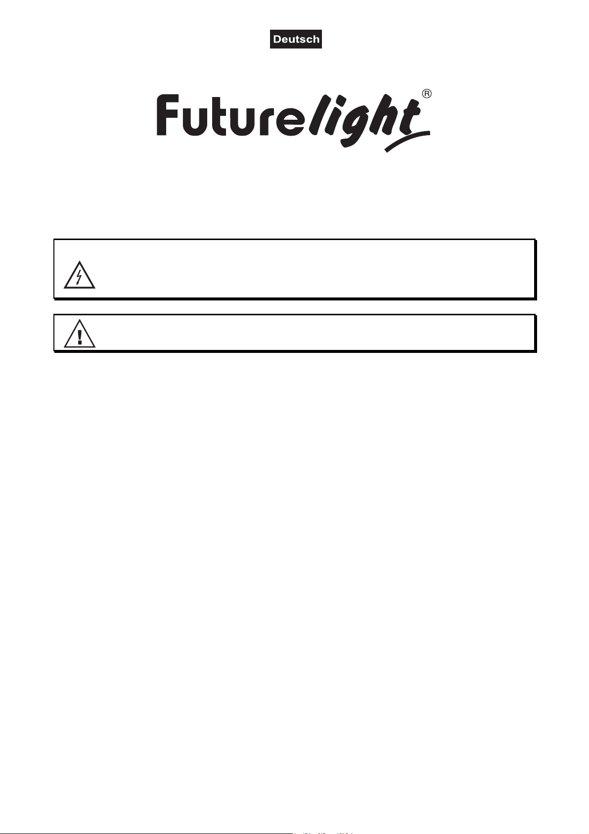
GERÄTEBESCHREIBUNG
6 7 8 9 105 11
1
2
3
4
12
15 16 17
13
14
18
19 20 21 22 23
(1) Objektivlinse
(2) Projektorarm
(3) Drahtlos-Anzeige
(4) Tragegriff
(5) Display
(6) Mikrofon
(7) Pfeil-Taste nach links
(8) ESDC-Schalter
(9) Pfeil-Taste nach unten
(10) Enter-Taste
(11) Pfeil-Taste nach rechts
(12) Pfeil-Taste nach oben
(13) Gummifuß
(14) 3-poliger DMX-Eingang
(15) 5-poliger DMX-Eingang
(16) 5-poliger DMX-Ausgang
(17) 3-poliger DMX-Ausgang
(18) Spannungsversorgungseingang
(19) Spannungsversorgungsausgang
(20) Montageplatte
(21) Sicherungshalter
(22) Netzschalter
(23) Gehäuseschraube
8/60
00123552.DOCX, Version 1.0
Page 9
INSTALLATION
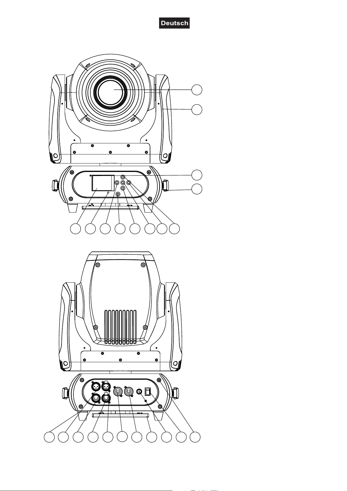
Einsetzen/Austauschen von Gobos
LEBENSGEFAHR!
Gobos nur bei ausgeschaltetem Gerät austauschen
Netzstecker ziehen!
Wenn Sie andere Formen und Muster als die Standard-Gobos verwenden möchten, oder Gobos
ausgetauscht werden sollen, gehen Sie wie folgt vor:
Niemals die Schrauben der rotierenden Gobos lösen,
da ansonsten die Kugellager geöffnet werden!
Entfernen Sie den Sprengring mit einem geeigneten Werkzeug. Entnehmen Sie das Gobo und setzen Sie
das neue Gobo ein. Drücken Sie den Sprengring zusammen und setzen Sie ihn vor das Gobo.
ACHTUNG!
Hinweis!
Slot-In-Gobo-System für Gobowechsel ohne Werkzeug!
Einsetzen/Austauschen der Gobos wie oben beschrieben.
9/60
00123552.DOCX, Version 1.0
Page 10
Projektormontage
WARNUNG! Verletzungsgefahr durch Herabfallen
Über Kopf installierte Geräte können beim Herabstürzen erhebliche Verletzungen verursachen!
Stellen Sie sicher, dass das Gerät sicher installiert ist und nicht herunterfallen kann. Die Montage
darf nur durch eine Fachkraft erfolgen, die mit den Gefahren und den einschlägigen Vorschriften
hierfür vertraut ist.
Die Aufhängevorrichtungen des Projektors muss so gebaut und bemessen sein, dass sie 1 Stunde lang
ohne dauernde schädliche Deformierung das 10-fache der Nutzlast aushalten kann.
Während des Auf-, Um- und Abbaus ist der unnötige Aufenthalt im Bereich von Bewegungsflächen, auf
Beleuchterbrücken, unter hochgelegenen Arbeitsplätzen sowie an sonstigen Gefahrbereichen verboten.
Nach der Montage muss das Gerät regelmäßig gewartet und überprüft werden, um mögliche Korrosion,
Verformung und Lockerung zu vermeiden.
Sichern Sie das Gerät mit einem Fangseil oder einer anderen geeigneten Einrichtung zusätzlich ab. Diese
zweite Aufhängung muss auf Grundlage der aktuellsten Arbeitsschutzbestimmungen ausreichend
dimensioniert und so angebracht sein, dass im Fehlerfall der Hauptaufhängung kein Teil der Installation
herabfallen kann.
Vorgehensweise:
Der Projektor sollte idealerweise außerhalb des Aufenthaltsbereiches von Personen installiert werden.
WICHTIG! ÜBERKOPFMONTAGE ERFORDERT EIN HOHES MAß AN ERFAHRUNG. Dies beinhaltet (aber
beschränkt sich nicht allein auf) Berechnungen zur Definition der Tragfähigkeit, verwendetes Installationsmaterial und regelmäßige Sicherheitsinspektionen des verwendeten Materials und des Projektors.
Versuchen Sie niemals, die Installation selbst vorzunehmen, wenn Sie nicht über eine solche Qualifikation
verfügen, sondern beauftragen Sie einen professionellen Installateur. Unsachgemäße Installationen können
zu Verletzungen und/oder zur Beschädigung von Eigentum führen.
Der Projektor muss außerhalb des Handbereichs von Personen installiert werden.
Wenn der Projektor von der Decke oder hochliegenden Trägern etc. abgehängt werden soll, muss immer mit
Traversensystemen gearbeitet werden. Der Projektor darf niemals frei schwingend im Raum befestigt
werden.
Achtung: Projektoren können beim Herabstürzen erhebliche Verletzungen verursachen! Wenn Sie Zweifel
an der Sicherheit einer möglichen Installationsform haben, installieren Sie den Projektor NICHT!
Montieren Sie den Projektor ausschließlich über zwei geeignete Haken. Bitte beachten Sie auch die
Installationshinweise auf der Unterseite der Base. Achten Sie darauf, dass das Gerät sicher befestigt wird.
Vergewissern Sie sich, dass die Verankerung stabil ist.
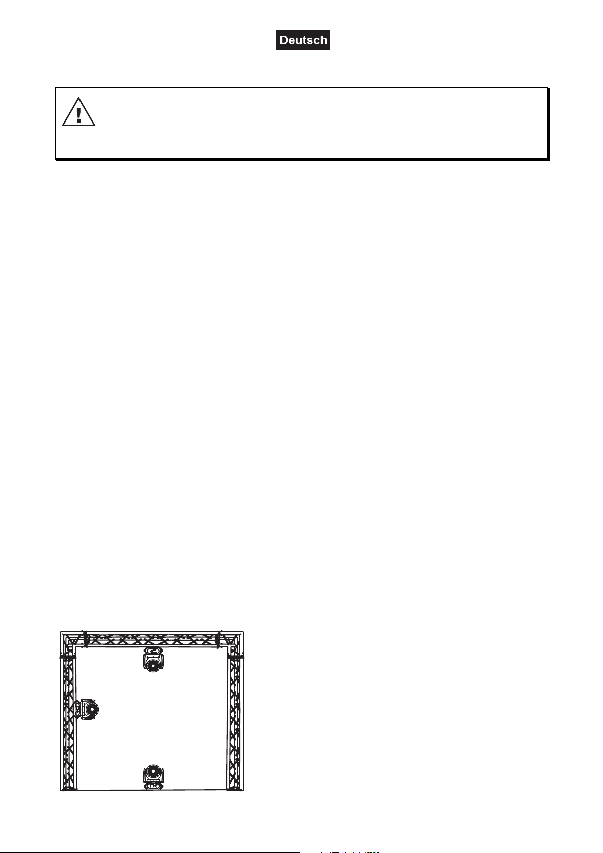
Die Projektorbase lässt sich auf zwei verschiedene Arten montieren.
Das Gerät kann direkt auf den Boden gestellt werden oder in
jeder möglichen Position im Trussing installiert werden, ohne
seine funktionellen Eigenschaften zu verändern.
Sichern Sie den Projektor bei Überkopfmontage (Montagehöhe
>100 cm) immer mit einem geeigneten Sicherungsseil.
Es dürfen nur Sicherungsseile und Schnellverbindungsglieder
gemäß DIN 56927, Schäkel gemäß DIN EN 1677-1 und BGV C1
Kettbiner eingesetzt werden. Die Fangseile,
Schnellverbindungsglieder, Schäkel und Kettbiner müssen auf
Grundlage der aktuellsten Arbeitsschutzbestimmungen (z. B.
BGV C1, BGI 810-3) ausreichend dimensioniert sein und korrekt
angewendet werden.
10/60
00123552.DOCX, Version 1.0
Page 11
1
2
3
4
Bitte beachten Sie: Bei Überkopfmontage in öffentlichen bzw. gewerblichen Bereichen ist eine Fülle von
Vorschriften zu beachten, die hier nur auszugsweise wiedergegeben werden können. Der Betreiber muss
sich selbständig um die Beschaffung der geltenden Sicherheitsvorschriften bemühen und diese einhalten!
Der Hersteller haftet nicht für Schäden, die durch unsachgemäße Installation und unzureichende Sicherheitsvorkehrungen verursacht werden!
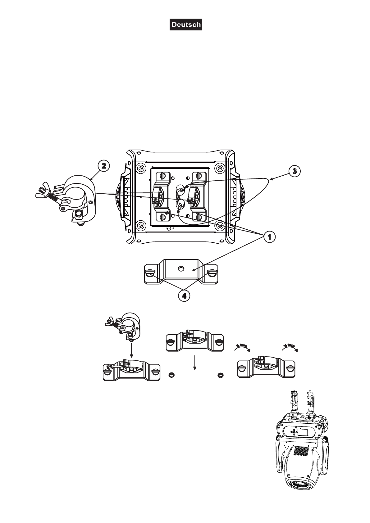
Hängen Sie das Schnellverschlussglied in dem dafür vorgesehenen Loch der Montageplatte am
Geräteboden ein. Führen Sie das Sicherungsseil über die Traverse bzw. einen sicheren Befestigungspunkt.
Hängen Sie das Ende in dem Schnellverschlussglied ein und ziehen Sie die Sicherungsmutter gut fest.
Der maximale Fallabstand darf 20 cm nicht überschreiten.
Ein Sicherungsseil, das einmal der Belastung durch Absturz ausgesetzt war oder beschädigt ist, darf nicht
mehr als Sicherungsseil eingesetzt werden.
(1) Omega-Halter
(2) Haken
(3) Sicherheitsfangseil
(4) Schnellverschluss
Verschrauben Sie beide Haken über eine M10 Schraube und selbstsichernde Mutter
mit den Omega-Haltern.
Führen Sie die beiden Schnellverschlüsse des ersten Omega-Halters in die dafür
vorgesehenen Öffnungen der Montageplatte an der Geräteunterseite ein. Drehen Sie
die Schnellverschlüsse im Uhrzeigersinn bis zum Anschlag fest. Installieren Sie den
zweiten Omega-Halter
11/60
00123552.DOCX, Version 1.0
Page 12
Einbau des optionalen drahtlos-Empfängers für WDMX-Betrieb (FUTURELIGHT WDR-G4)
ACHTUNG!
Vor Einbau des Moduls das Gerät vom Netz trennen.
Gefahr eines elektrischen Schlages!
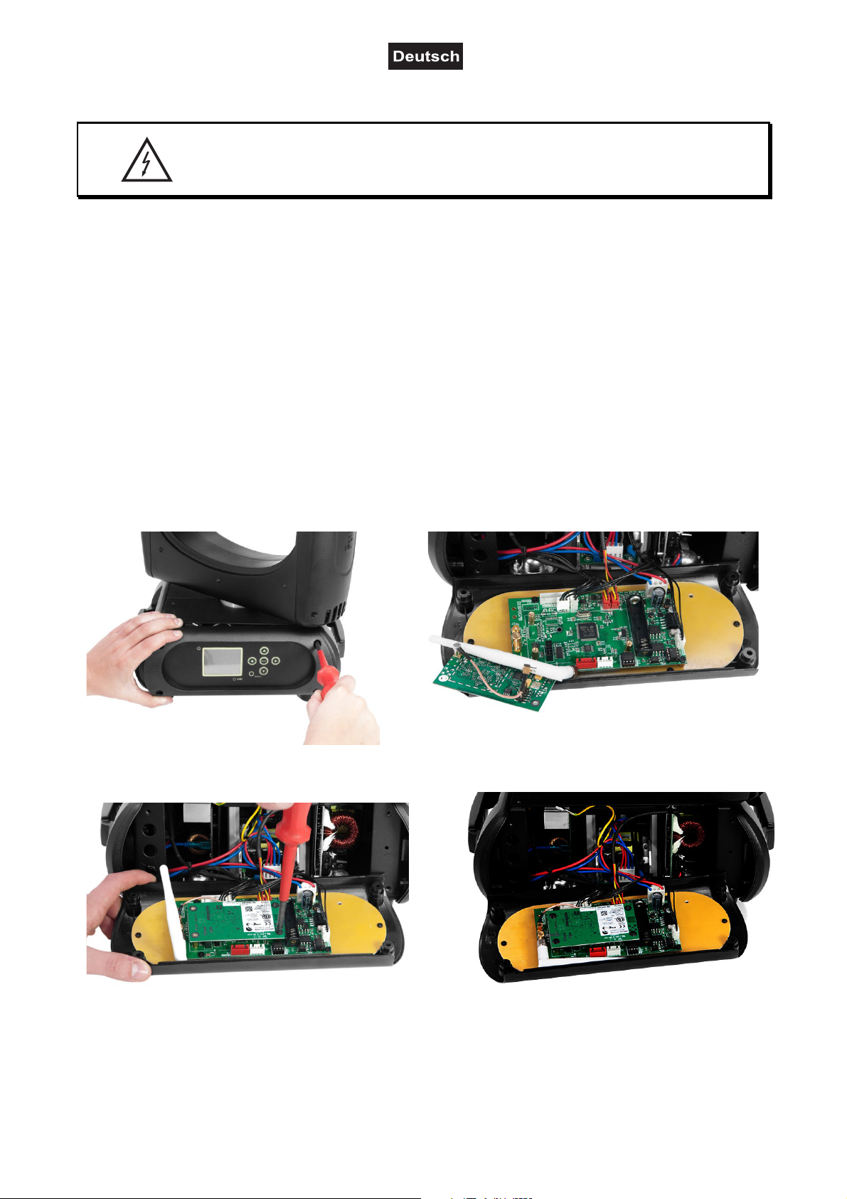
Installationsschritte
1. Nehmen Sie den Drahtlos-DMX-Empfänger aus der Verpackung. Das Modul besteht aus einer
Stabantenne mit Gewinde, der Wireless-Platine und einem Verbindungskabel.
2. Entfernen Sie nun die vier Schrauben des Control-Boards, an der Gerätevorderseite und klappen Sie die
Control-Board-Abdeckung vorsichtig nach vorne. Auf der linken Seite des Display-Boards befinden sich
die beiden Anschlussbuchsen für den Drahtlos-DMX-Empfänger.
3. Schrauben Sie zuerst die Stabantenne auf der Antennenbuchse fest und legen Sie die Antenne entlang
des Display-Boards in die Control-Board-Abdeckung.
4. Zur Befestigung des Wireless-Moduls lösen Sie die drei Schrauben auf den Distanzbolzen und entfernen
Sie sie. Stecken Sie die Steckkontakte des Wireless-Moduls in die Buchse auf dem Display-Board und
schrauben die drei Schrauben wieder fest. Stecken Sie den Antennenstecker des Verbindungskabels in
die dafür vorgesehene Buchse.
5. Klappen Sie die Control-Board-Abdeckung vorsichtig wieder zu und schrauben die vier Schrauben an
der Vorderseite wieder fest.
A B
C D
12/60
00123552.DOCX, Version 1.0
Page 13
ANSCHLÜSSE
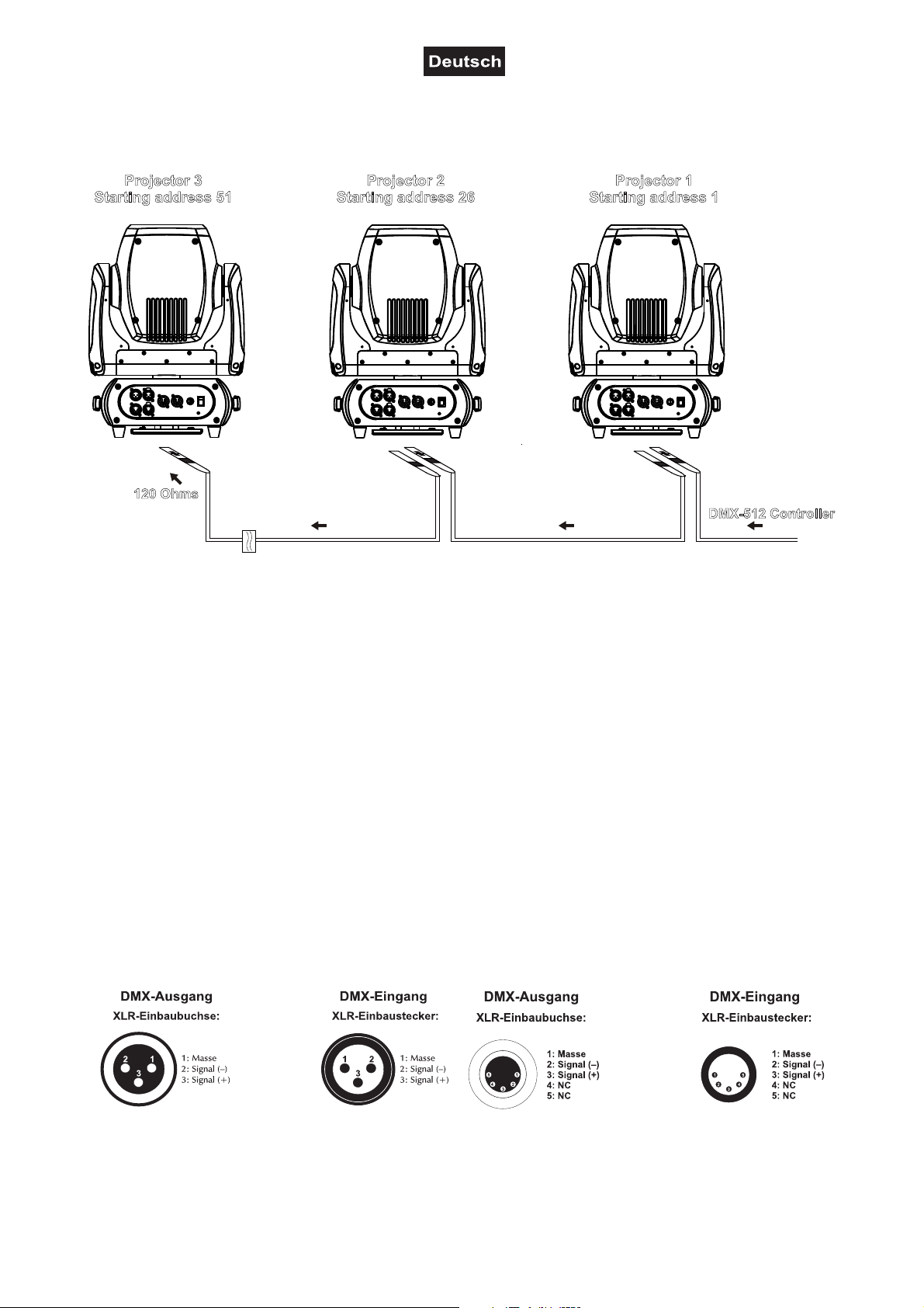
Anschluss an den DMX-512 Controller / Verbindung Projektor – Projektor
Projector 3
Starting address 51
120 Ohms
Projector 2
Starting address 26
Projector 1
Starting address 1
DMX-512 Controller
Achten Sie darauf, dass die Adern der Datenleitung an keiner Stelle miteinander in Kontakt treten. Die
Geräte werden ansonsten nicht bzw. nicht korrekt funktionieren.
Beachten Sie, dass die Startadresse abhängig vom verwendeten Controller ist. Unbedingt die Bedienungsanleitung des verwendeten Controllers beachten.
DMX512-Ansteuerung
Für die Ansteuerung des Geräts per DMX512 ist eine Datenverbindung notwendig. Das Gerät verfügt dazu
über 3-polige und 5-polige XLR-Anschlüsse.
1. Verbinden Sie den Ausgang Ihres Controllers mit dem DMX-Eingang DMX IN des Gerätes über ein
DMX-Kabel.
2. Verbinden Sie den DMX-Ausgang DMX OUT des Gerätes mit dem DMX-Eingang des nächsten
Geräts in der Kette. Verbinden Sie immer einen Ausgang mit dem Eingang des nächsten Geräts bis
alle Geräte angeschlossen sind. Nicht als Signalsplitter geeignet!
3. Am letzten Gerät muss die DMX-Leitung durch einen Abschlusswiderstand abgeschlossen werden.
Dazu wird ein XLR-Stecker in den DMX-Ausgang am letzten Gerät gesteckt, bei dem zwischen
Belegung der XLR-Verbindung:
Signal (–) und Signal (+) ein 120-Ω-Widerstand eingelötet ist.
13/60
00123552.DOCX, Version 1.0
Page 14

Anschluss ans Netz
Das Gerät verfügt über ein Schaltnetzteil, das eine Netzspannung zwischen 100 und 240 Volt erlaubt.
1 Schließen Sie das beiliegende Netzkabel an und stecken den Netzstecker in eine geerdete
Schutzkontaktsteckdose ein.
2 Schließen Sie das Gerät nicht über einen Dimmer an die Netzspannung an. Für besseren Bedienkomfort
verwenden Sie eine schaltbare Steckdose.
Stromversorgung von weiteren Geräten
Über den Netzausgang POWER OUT können weitere Geräte mit Strom versorgt werden. Zum
Zusammenschalten der Geräte, verbinden Sie immer den Ausgang POWER OUT mit dem Eingang POWER
IN des nächsten Geräts bis alle Geräte angeschlossen sind. Passende Netzkabel mit P-Con-Stecker sind
optional erhältlich. Auf diese Weise lassen sich bis zu 8 Geräte bei 230/240 Volt Netzspannung und bis zu 4
Geräte bei 110/115 Volt Netzspannung zusammenschalten.
BEDIENUNG
Über den Netzschalter lässt sich das Gerät ein- bzw. ausschalten. Wenn Sie das Gerät an die
Spannungsversorgung angeschlossen haben, nimmt das Gerät den Betrieb auf. Während des Reset
justieren sich die Motoren aus und das Gerät ist danach betriebsbereit.
Standalone-Betrieb
Das Gerät lässt sich im Standalone-Betrieb ohne Controller einsetzen. Trennen Sie dazu den DMH-160 MK2
vom Controller und rufen Sie das vorprogrammierte Programm auf. Bitte beachten Sie weitere Hinweise
unter Control Board.
Master/Slave-Betrieb
Im Master/Slave-Betrieb lassen sich mehrere Geräte synchronisieren, die dann von einem Master-Gerät
gesteuert werden.
An der Rückseite des Gerätes befindet sich eine XLR-Einbaubuchse (DMX Out) und ein XLR-Einbaustecker
(DMX In), über die sich mehrere Geräte miteinander verbinden lassen.
Wählen Sie das Gerät aus, das zur Steuerung der Effekte dienen soll. Dieses Gerät arbeitet dann als
Master-Gerät und steuert alle weiteren Slave-Geräte, die über ein DMX-Kabel mit dem Master-Gerät
verbunden werden. Stecken Sie das DMX-Kabel in die DMX OUT-Buchse und verbinden Sie es mit dem
DMX IN-Stecker des nächsten Gerätes.
Stellen Sie beim Master-Gerät den gewünschten Master-Mode ein. Stellen Sie bei allen Slave-Geräten den
entsprechenden Slave-Mode ein. Bitte beachten Sie weitere Hinweise unter Control Board.
DMX-gesteuerter Betrieb
Über Ihren DMX-Controller können Sie die einzelnen Geräte individuell ansteuern. Dabei hat jeder DMXKanal eine andere Belegung mit verschiedenen Eigenschaften. Die einzelnen DMX-Kanäle und ihre
Eigenschaften sind unter DMX-Protokoll aufgeführt.
Das Gerät verfügt über vier verschiedene DMX-Kanal-Modi. Über das Control Board können Sie den DMXKanal-Modus definieren.
Adressierung des Projektors
Über das Control Board können Sie die DMX-Startadresse definieren. Die Startadresse ist der erste Kanal,
auf den der Projektor auf Signale vom Controller reagiert.
Wenn Sie die Startadresse, im 25 Kanal-Modus, z. B. auf 26 definieren, belegt der Projektor die
Steuerkanäle 26 bis 50.
Bitte vergewissern Sie sich, dass sich die Steuerkanäle nicht mit anderen Geräten überlappen, damit der
DMH-160 MK2 korrekt und unabhängig von anderen Geräten in der DMX-Kette funktioniert.
14/60
00123552.DOCX, Version 1.0
Page 15

Werden mehrere DMH-160 MK2 auf eine Adresse definiert, arbeiten sie synchron.
Bitte beachten Sie:
Schalten Sie das Gerät ein. Das Gerät prüft, ob DMX-512 Daten empfangen werden oder nicht. Werden
keine Daten empfangen, blinkt das Display.
Die Meldung erscheint
-wenn kein XLR-Kabel (DMX Signalkabel vom Controller) in die DMX-Eingangsbuchse des Gerätes gesteckt
wurde.
-wenn der Controller ausgeschaltet oder defekt ist.
-das Kabel oder der Stecker defekt ist oder das Signalkabel nicht richtig eingesteckt ist.
Die Farben, Farb- und Goborad-Positionen des folgenden DMX-Protokolls sind wie folgt angeordnet.
Pos. 17
Pos. 16
Pos. 15
Pos. 14
Offen/
Open
Magenta
Pos. 13
Orange
Pos. 1
Hellblau/
Light blue
Pos. 12
Farbrad
Pos. 2
Rot/
Red
Pos. 11
Color-wheel
Rosa/
Pink
Pos. 10
Pos. 3
Blau/
Blue
Grün/
Green
Gelb/
Yellow
Pos. 9
Pos. 4
Pos. 5
Pos. 6
Pos. 7
Pos. 8
Position 7
Position 6
Position 5
Rotierendes Goborad
Offen/
Open
Position 4
Rotating gobo-wheel
Position 1
Position 2
Position 3
Position 5
Position 4
Position 3
Statisches Goborad
Position 6
Position 2
Static gobo-wheel
Position 7
Offen/
Open
Position 1
DMX-Protokoll
Modus/Kanal Wert Eigenschaft
St. Ex.
Basic
1 1 1 1
8bit
Basic
16bit
0 255
Horizontale Bewegung (PAN)
Wenn Sie den Regler verschieben, bewegen Sie den Kopf horizontal
(PAN). Allmähliches Einstellen des Kopfes bei langsamen Schieben
des Reglers (0-255, 128-Mitte). Der Kopf kann an jeder gewünschten
Einstellung angehalten werden.
PAN-Bewegung mit 16 Bit-Auflösung
2 2 2
0 255 Feinindizierung
3 3 2 3
0 255
Vertikale Bewegung (TILT)
Wenn Sie den Regler verschieben, bewegen Sie den Kopf vertikal
(TILT). Allmähliches Einstellen des Kopfes bei langsamen Schieben
des Reglers (0-255, 128-Mitte). Der Kopf kann an jeder gewünschten
Einstellung angehalten werden.
TILT-Bewegung mit 16 Bit-Auflösung
4 4 4
0 255 Feinindizierung
5 5 3 5
6
6 7
0 255
0 15
16 31
32 255
0 15 Normale Shutter Funktionen
Geschwindigkeit PAN-/TILT-Bewegung
Abnehmende Geschwindigkeit
Funktion PAN-/TILT-Bewegung
Normal
Blackout bei PAN-/TILT-Bewegung
Keine Funktion
Funktion Shutter, Strobe
15/60
00123552.DOCX, Version 1.0
Page 16
16 31 Öffnender Puls-Effekt
32 47 Schließender Puls-Effekt
48 63 Strobe-Effekt über Zufallsgenerator
64 255 Keine Funktion
Shutter, Strobe
7 8
4 6
8 9 5 7
10
9 11
10 12
0 31 Geschlossen
32 223 Strobe-Effekt mit zunehmender Geschwindigkeit
224 255 Offen
0 31 Geschlossen
32 223 Strobe-Effekt mit zunehmender Geschwindigkeit
224 255 Offen
0 31 Geschlossen
32 223 Strobe-Effekt mit zunehmender Geschwindigkeit
224 255 Offen
0 31 Geschlossen
32 223 Strobe-Effekt mit zunehmender Geschwindigkeit
224 255 Offen
0 31 Shutter geschlossen
32 63 Keine Funktion (Shutter offen)
64 95 Strobe-Effekt mit zunehmender Geschwindigkeit
96 127 Keine Funktion (Shutter offen)
128 159 Puls-Effekt in Sequenzen
160 191 Keine Funktion (Shutter offen)
192 223
224 255 Keine Funktion (Shutter offen)
0 255 Allmähliche Einstellung der Dimmerintensität von 0 bis 100 %
0 255 Allmähliche Einstellung der Dimmerintensität von 0 bis 100 %
0 15
16 31
32 47
48 63
64 79
80 111
112 255
0 13
14 27
28 41
42 55
Normale Shutter Funktionen
Öffnender Puls-Effekt
Schließender Puls-Effekt
Strobe-Effekt über Zufallsgenerator
Shutter, Strobe
Strobe-Effekt über Zufallsgenerator mit zunehmender
Geschwindigkeit
Dimmerintensität
Dimmerintensität mit 16 Bit-Auflösung
Funktion Farben
Normaler Farbwechsel
Blackout bei Farbwechsel
Rainboweffekt vorwärts
Rainboweffekt rückwärts
Farbwechsel an jeder Position
Schneller Farbsprung
Keine Funktion
Farbrad
Normaler Farbwechsel / Blackout bei Farbwechsel / schneller
Farbsprung
Offen
Position 1
Position 2
Position 3
16/60
00123552.DOCX, Version 1.0
Page 17
6 8
56 69
70 83
84 97
98 111
112 125
126 139
140 153
154 167
168 181
182 195
196 209
210 223
224 237
238 255
0 255
0 255
0 255
0 2
3 5
6 8
9 11
12 14
15 17
18 20
21 23
24 26
27 29
30 32
33 35
36 38
39 41
42 44
45 47
48 50
51 53
54 56
57 59
60 62
63 65
66 68
69 71
72 74
75 77
78 80
81 83
84 86
Position 4
Position 5
Position 6
Position 7
Position 8
Position 9
Position 10
Position 11
Position 12
Position 13
Position 14
Position 15
Position 16
Position 17
Rainboweffekt vorwärts
Mit zunehmender Geschwindigkeit
Rainboweffekt rückwärts
Mit zunehmender Geschwindigkeit
Farbwechsel an jeder Position
Positionierung von 0 - 360 Grad
Farbrad
Normaler Farbwechsel
Offen
Position 1
Position 2
Position 3
Position 4
Position 5
Position 6
Position 7
Position 8
Position 9
Position 10
Position 11
Position 12
Position 13
Position 14
Position 15
Position 16
Position 17
Blackout bei Farbwechsel
Offen
Position 1
Position 2
Position 3
Position 4
Position 5
Position 6
Position 7
Position 8
Position 9
Position 10
17/60
00123552.DOCX, Version 1.0
Page 18
11 13
12 14
7 9
87 89
90 92
93 95
96 98
99 101
102 104
105 106
107 119
120 132
133 145
146 158
159 171
172 184
185 197
198 210
211 223
224 239
240 255
0 15
16 31
32 47
48 63
64 79
80 95
96 255
0 31
32 63
64 95
96 127
128 159
160 191
192 223
224 255
0 7
8 255 Mit zunehmender Geschwindigkeit
0 7
8 255 Mit zunehmender Geschwindigkeit
0 255
0 5
6 11
Position 11
Position 12
Position 13
Position 14
Position 15
Position 16
Position 17
Schneller Farbsprung
Position 1
Position 2
Position 3
Position 4
Position 5
Position 6
Position 7
Position 8
Position 9
Rainboweffekt vorwärts
Mit zunehmender Geschwindigkeit
Rainboweffekt rückwärts
Mit zunehmender Geschwindigkeit
Funktion rotierendes Goborad, Gobo-Shake
Normaler Gobowechsel
Blackout bei Gobowechsel
Rotierendes Goborad vorwärts
Rotierendes Goborad rückwärts
Gobowechsel an jeder Position
Gobo-Shake
Keine Funktion
Rotierendes Goborad, Gobo-Shake
Normaler Gobowechsel / Blackout bei Gobowechsel / Gobo-Shake
Offen
Position 1
Position 2
Position 3
Position 4
Position 5
Position 6
Position 7
Rotierendes Goborad vorwärts
Stopp
Rotierendes Goborad rückwärts
Stopp
Gobowechsel an jeder Position
Positionierung von 0 - 360 Grad
Rotierendes Goborad, Gobo-Shake
Normaler Gobowechsel
Offen
Position 1
18/60
00123552.DOCX, Version 1.0
Page 19

13 15
14 16
12 17
18 23
24 29
30 35
36 41
42 47
48 53
54 59
60 65
66 71
72 77
78 83
84 89
90 97
98 115
116 133
134 151
152 169
170 187
188 205
206 223
224 224
225 239
240 240
241 255
0 15
16 31
32 47
48 63
64 79
80 95
96 111
112 255
0 255
0 7
8 255
0 7
8 255
0 255
Position 2
Position 3
Position 4
Position 5
Position 6
Position 7
Blackout bei Gobowechsel
Offen
Position 1
Position 2
Position 3
Position 4
Position 5
Position 6
Position 7
Gobo-Shake
Position 1
Position 2
Position 3
Position 4
Position 5
Position 6
Position 7
Rotierendes Goborad vorwärts
Stopp
Mit zunehmender Geschwindigkeit
Rotierendes Goborad rückwärts
Stopp
Mit zunehmender Geschwindigkeit
Rotierendes Goborad, Gobo-Rotation
Goboindizierung
Rotierendes Goborad vorwärts
Rotierendes Goborad rückwärts
Bewegungsmakro vorwärts
Bewegungsmakro vorwärts mit Blackout
Bewegungsmakro rückwärts
Bewegungsmakro rückwärts mit Blackout
Keine Funktion
Rotierendes Goborad, Gobo-Geschwindigkeit
Goboindizierung
Positionierung von 0 - 360 Grad
Rotierendes Goborad vorwärts
Stopp
Mit zunehmender Geschwindigkeit
Rotierendes Goborad rückwärts
Stopp
Mit zunehmender Geschwindigkeit
Bewegungsmakro vorwärts & Bewegungsmakro vorwärts mit
Blackout
Mit zunehmender Geschwindigkeit
19/60
00123552.DOCX, Version 1.0
Page 20

8 10
15 17
16 18
9 11
0 255
0 191
192 207
208 223
224 224
225 239
240 240
241 255
0 15
16 31
32 47
48 63
64 79
80 95
96 255
0 31
32 63
64 95
96 127
128 159
160 191
192 223
224 255
0 255
0 255 Mit zunehmender Geschwindigkeit
0 255 Positionierung von 0 - 360 Grad
0 5
6 11
12 17
18 23
24 29
30 35
36 41
42 47
48 53
Bewegungsmakro rückwärts & Bewegungsmakro rückwärts mit
Blackout
Mit zunehmender Geschwindigkeit
Rotierendes Goborad, Gobo-Geschwindigkeit
Goboindizierung
Positionierung von 0 - 360 Grad
Bewegungsmakro vorwärts
Mit zunehmender Geschwindigkeit
Bewegungsmakro vorwärts
Mit zunehmender Geschwindigkeit
Goborotation vorwärts
Stopp
Mit zunehmender Geschwindigkeit
Goborotation rückwärts
Stopp
Mit zunehmender Geschwindigkeit
Funktion statisches Goborad, Gobo-Shake
Normaler Gobowechsel
Blackout bei Gobowechsel
Rotierendes Goborad vorwärts
Rotierendes Goborad rückwärts
Gobowechsel an jeder Position
Gobo-Shake
Keine Funktion
Statisches Goborad, Gobo-Shake
Normaler Gobowechsel / Blackout bei Gobowechsel / Gobo-Shake
Offen
Position 1
Position 2
Position 3
Position 4
Position 5
Position 6
Position 7
Rotierendes Goborad vorwärts
Mit zunehmender Geschwindigkeit
Rotierendes Goborad rückwärts
Gobowechsel an jeder Position
Statisches Goborad, Gobo-Shake
Normaler Gobowechsel
Offen
Position 1
Position 2
Position 3
Position 4
Position 5
Position 6
Position 7
Blackout bei Gobowechsel
Offen
20/60
00123552.DOCX, Version 1.0
Page 21

17 19 10 12
18 20 11 13
19 21
20 22 12 14
21 23
54 59
60 65
66 71
72 77
78 83
84 89
90 97
98 115
116 133
134 151
152 169
170 187
188 205
134 223
224 239 Mit zunehmender Geschwindigkeit
240 255 Mit zunehmender Geschwindigkeit
0 63
64 127
128 191
192 255
0 3
4 127
128 131
132 255
0 15
16 31
32 47
48 63
64 95
96 127
128 255
0 255 Nah bis weit
0 255 Feinfokussierung nah bis weit
0 15
16 31
32 47
48 63
64 95
Position 1
Position 2
Position 3
Position 4
Position 5
Position 6
Position 7
Gobo-Shake
Position 1
Position 2
Position 3
Position 4
Position 5
Position 6
Position 7
Rotierendes Goborad vorwärts
Rotierendes Goborad rückwärts
Prisma
Offen
3-Facetten-Prisma
8-Facetten-Prisma
Frost
Prismenrotation
Rotierendes Prisma vorwärts
Stopp
Mit zunehmender Geschwindigkeit (Stopp bis schnellste
Geschwindigkeit)
Rotierendes Prisma rückwärts
Stopp
Mit zunehmender Geschwindigkeit (Stopp bis schnellste
Geschwindigkeit)
Funktion Fokus
Allmähliche Einstellung von nah bis weit
5 m Autofokus (Fokussieren auf Gobos und Iris)
7,5 m Autofokus (Fokussieren auf Gobos und Iris)
10 m Autofokus (Fokussieren auf Gobos und Iris)
15 m Autofokus (Fokussieren auf Gobos und Iris)
> 20 m Autofokus (Fokussieren auf Gobos und Iris)
Keine Funktion
Fokus
Allmähliche Einstellung von nah bis weit
Autofokus
Funktion Iris
Irisindizierung
Öffnender Pulseffekt mit zunehmender Geschwindigkeit
Öffnender Pulseffekt mit abnehmender Geschwindigkeit
Schließender Pulseffekt mit zunehmender Geschwindigkeit
Schließender Pulseffekt mit abnehmender Geschwindigkeit
21/60
00123552.DOCX, Version 1.0
Page 22

22 24
13 15
23 25 14 16
96 255
0 255
0 255
0 191
192 207
208 223
224 239
240 255
0 7 Keine Funktion
8 15 Reset Alle
16 23 Reset PAN/TILT
24 31 Reset Farben
32 39 Reset Gobos
40 47 Keine Funktion
48 55 Reset Übrige
56 63 Display aus
64 71 Display an
72 79 Keine Funktion
80 87 Keine Funktion
88 95 Standby-Modus
96 255
Keine Funktion
Iris
Irisindizierung
Allmähliche Einstellung des Durchmessers von Max. nach Min.
Öffnender Pulseffekt / schließender Pulseffekt
Pulseffekt mit zunehmender Geschwindigkeit
Funktion Iris
Irisindizierung
Öffnender Pulseffekt mit zunehmender Geschwindigkeit
Öffnender Pulseffekt mit abnehmender Geschwindigkeit
Schließender Pulseffekt mit zunehmender Geschwindigkeit
Schließender Pulseffekt mit abnehmender Geschwindigkeit
Reset, Displaysteuerung
Keine Funktion
22/60
00123552.DOCX, Version 1.0
Page 23

Control Board
Das Control Board bietet mehrere Möglichkeiten: so lassen sich z. B. die DMX-Startadresse eingeben, das
vorprogrammierte Programm abspielen oder ein Reset durchführen.
Drücken Sie die Enter-Taste, so dass sich das Display einschaltet. Durch Drücken der geeigneten PfeilTaste (nach unten, nach oben, nach links und nach rechts) können Sie sich im Hauptmenü bewegen. Zur
Auswahl des gewünschten Menüpunktes drücken Sie die Enter-Taste. Durch Drücken der geeigneten PfeilTaste können Sie die Auswahl verändern. Bestätigen Sie jede Änderung durch Drücken der Enter-Taste. Die
jeweiligen Funktionen werden im Folgenden beschrieben.
Vorgabewerte grau unterlegt 1 Basic Reload / 2 Program Reload / 3 Private Reload
Hauptmenü
DMX Address 1
Connect
Wireless 1
Max Temperature
Light
1
Lamp Adjust
Time info
Untermenü
60-139°C,90°C/140-282°F,194°F
PAN ...
Service-Funktion
Current XXXX (h)
Display Funktion
Einstellen der DMXStartadresse
Wireless DMX aktivieren
(Sonderausstattung optional)
LED aus bei
Temperaturerreichung
Betriebsstunden Gerät
seit Einschalten
Fixture Life XXXX (h) Betriebsstunden Gerät
Temperature Near Lamp Temp. ... XXX °C/°F Innentemperatur
Fans Speed Near Lamp Fan Lüftergeschwindigkeit
Channel Value
Error Message PAN, TILT ... Kanalfehler
Information
Fixture Model Xxxxxxxxxxxxx
Software Ver
PAN ... PAN = XXX ... DMX-Anzeiger
Gerätemodell und Marke
1U01 V 1.0.00
2U01 V 1.0.00 ...
All
Reset Alle
Software Version jedes
ICs
PAN&TILT Reset PAN/TILT
Reset
Colors Reset Farben
Gobos Reset Gobos
Others Reset Übrige
PAN reverse ON/OFF
TILT reverse ON/OFF
PAN degree 630/540
Movement 1
Encoders ON/OFF
Set
PAN/TILT Mode Stand/Smooth
Mic Sens 3 0~99%, 60%
No Signal 1
Close/Hold/Auto/Music
Temperature C/F 1 Celsius/Fahrenheit
UI Set
Fans Mode 1 Auto Speed
Hibernation 1 OFF, 01M-99M, 15M
Backlight
Flip Display 1
Display Bright 3
Brand Show 1
Key Lock 1
Language 1
1 02M-60M, 02M Display-Abschaltung
ON/OFF
00-31 10
ON/OFF
ON/OFF
En/Po/Fr/Sp
/High Speed
PAN/TILT-Umkehr
PAN-Winkel zwischen
630° und 540°
umschaltbar
Automatic PAN/TILT
calibration
PAN/TILT Geschwindigkeit
einstellen
Mikrofonempfindlichkeit
Auto-Modus wenn kein
DMX
Temperatureinheit zw. °C
und °F umschalten
Lüfter Betriebsart einst.
Standby-Modus
Display-Umkehrung um 180°
Display-Helligkeit
Markennamen anzeigen
Tastensperre aktivieren
Sprachauswahl
23/60
00123552.DOCX, Version 1.0
Page 24

Silent Mode ON/OFF Geräuscharmer Modus
Fixture Set 1
Frequency
600Hz/1200Hz/2000Hz/
2400Hz/4000Hz/25000Hz
PWM (Pulsweitenmodulation)
Standard
Users
User Mode 1
Extended
Basic-8bit
Basic-16bit
DMX-Kanal-Modus/
Benutzerdefinierte
Kanalreihenfolge
User
Max Channel = XX
PAN = CH01 ...
Password=XXX
Color =XXX ...
ON/OFF
ON/OFF
ON/OFF
ON/OFF
XXX
ON/OFF
ON/OFF
Preset-Benutzerd.
Effektradjustierung;
Standardposition
Passwort „050“
Name
Passwort „050“
PID-Code für RDM
einstellen
Durchschleifen von Daten
Empfänger ausloggen
(Sonderausstattung optional)
Basis Reload
Programm Reload
Password: 050
Privater Reload
Reload Alles
Calibration 3
Set
Fixture ID 3
Wireless Set 1
Reload Default
Edit User 3
--Password-Color ...
Name
--Password-PID Code
DMX on cable
Reset Connect
Basic Reload 1
Program Reload 2
--Password-Private Reload 3
All Reload
DMX receive Zurück zum DMX-Mode
Slave receive Slave 1, Slave 2, Slave 3 Slave-Einstellung
Play 1
Select Chase 2
Program
Edit Chase 2
Edit Scenes 2
Scenes Record ScXX=>ScXX
Sequence Master/Alone Autom. Programm Run
Music Master/Alone
Chase Part 1
Chase Part 2
Chase Part 3
Chase 1
:
Chase 8
Edit scene 001
:
Edit scene 250
Chase 1- 8 Chase 1
Chase 1- 8 Chase 2
Chase 1- 8 Chase 3
Chase Test
Step 01 = SCXXX
Step 64 = SCXXX
Pan,Tilt, ...
-- Fade Time --
-- Scene Time -DMX Input
Musikgesteuerter
Programm Run
Programmwahl für Auto
Programm
Testprogramm
Programm Auto Run
Speichern + los
Speichern + zurück
Szenen manuell editieren
Automatische
Szenenaufzeichnung
Connect
Einstellen der DMX-Startadresse
Mit dieser Funktion können Sie die DMX-Startadresse über das Control Board einstellen.
• Wählen Sie “DMX Address” durch Drücken der Up/Down-Tasten.
• Drücken Sie die Enter-Taste und stellen Sie die DMX-Adresse durch Drücken der Up/Down-Tasten ein.
• Drücken Sie die Enter-Taste zur Bestätigung.
Wireless
Ein optional erhältlicher Drahtlos-Empfänger für WDMX-Betrieb (Wireless Solution - made in Sweden) kann
nachgerüstet werden.
Mit der Funktion „Wireless“ können Sie den Drahtlos-Empfänger am Drahtlos-Sender einloggen, das Gerät
kann nun drahtlose Signale empfangen.
24/60
00123552.DOCX, Version 1.0
Page 25

• Wählen Sie “Wireless” durch Drücken der Up/Down-Tasten.
• Drücken Sie die Enter-Taste zur Bestätigung.
Ist ein Gerät mit eingebautem Drahtlos-Empfänger über ein Kabel mit einem DMX-Controller verbunden,
wird es von dem kabelgebundenen Controller angesteuert und nicht vom Drahtlos-Sender.
Light
Max Temperatur
Mit dieser Funktion kann das Gerät so programmiert werden, dass die LED automatisch abgeschaltet wird,
wenn eine bestimmte Innentemperatur erreicht wird. Drücken Sie die Up/Down-Tasten zur Auswahl der
maximalen Innentemperatur zwischen 60 °C und 139 °C. Die normale Betriebstemperatur sollte unter 90 °C
liegen. 90 °C Innentemperatur und mehr sind bereits als kritisch zu bewerten und sollten zur Abschaltung
der LED führen. Bitte beachten Sie, dass die Umgebungstemperatur niemals über 45 °C liegen sollte, damit
eine ausreichende Kühlung gewährleistet ist.
Information
Time information
Betriebsstunden Gerät seit dem Einschalten (current)
Mit dieser Funktion lassen sich die temporären Betriebsstunden des Gerätes seit dem Einschalten auslesen.
Auf dem Display erscheint “XXXX”, “X“ steht für die Anzahl der Stunden. Der Zähler wird beim Abschalten
auf 0 zurückgesetzt.
Betriebsstunden Gerät (Fixture Life)
Mit dieser Funktion lassen sich die Betriebsstunden des Gerätes auslesen. Auf dem Display erscheint
“XXXX”, “X“ steht für die Anzahl der Stunden.
Temperatur
Innentemperatur
Temperaturangabe im Inneren des Projektorkopfes (nahe CMY-Filter) in Grad Celsius/Grad Fahrenheit.
...
Lüftergeschwindigkeit
Mit dieser Funktion lässt sich die aktuelle Lüftergeschwindigkeit auslesen. Auf dem Display erscheint
“XXXX”, “X“ steht für U/min.
DMX-Anzeiger
Mit dieser Funktion können Sie auslesen, mit welchem Wert der entsprechende Kanal gesendet wird.
Kanalfehler
Mit dieser Funktion können Sie Kanal Fehler auslesen.
Gerätemodell
Mit dieser Funktion können Sie das Modell und die Marke des Gerätes auslesen.
Software version
Mit dieser Funktion lässt sich die Software-Version jedes ICs auslesen.
• Wählen Sie “Software ver.” durch Drücken der Up/Down-Tasten.
• Drücken Sie die Enter-Taste, auf dem Display erscheint z. B. “1U01 VX.X.XX”, “X.X.xx“ steht für die
Versionsnummer.
Set
Reset
Mit dieser Funktion lässt sich über das Control Board ein Reset durchführen. Dabei können Sie über die
Up/Down-Tasten die verschiedenen Reset-Funktionen auswählen.
Movement
PAN-Umkehr
Mit dieser Funktion lässt sich die PAN-Bewegung umkehren.
TILT-Umkehr
Mit dieser Funktion lässt sich die TILT-Bewegung umkehren.
25/60
00123552.DOCX, Version 1.0
Page 26

PAN-Winkel zwischen 630° und 540° umschalten
Mit dieser Funktion lässt sich der PAN-Winkel einstellen.
• Wählen Sie “Pan degree” durch Drücken der Up/Down-Tasten.
• Drücken Sie die Enter-Taste, auf dem Display erscheint “540”.
• Drücken Sie die Up/Down-Taste, um “540“ oder “630” auszuwählen.
• Drücken Sie die Enter-Taste zur Bestätigung.
Automatische PAN/TILT Kalibrierung
Mit der Funktion "Encoders" lassen sich die PAN- und TILT-Bewegung auf die korrekten
Ausgangspositionen kalibrieren.
PAN/TILT Geschwindigkeit einstellen
Mit dieser Funktion können Sie die PAN/TILT Geschwindigkeit definieren. Sie haben die Wahl zwischen zwei
unterschiedlichen Modi.
UI Set
Mikrofonempfindlichkeit
Mit dieser Funktion lässt sich die Mikrofonempfindlichkeit zwischen 0 % und 99 % einstellen.
• Wählen Sie “Mic Sens” durch Drücken der Up/Down-Tasten.
• Drücken Sie die Up/Down-Taste, um die gewünschte Empfindlichkeit einzustellen.
• Drücken Sie die Enter-Taste zur Bestätigung.
Auto-Modus wenn kein DMX
Mit der Funktion "No Signal“ lassen sich verschiedene Modi einstellen, wenn kein DMX-Signal empfangen
wird.
• Wählen Sie "Close, Hold, Auto oder Music" durch Drücken der Up/Down-Tasten.
• Drücken Sie die Up/Down-Taste, um "Close", "Hold", "Auto" oder "Music" auszuwählen.
• Drücken Sie die Enter-Taste zur Bestätigung.
Temperatureinheit zwischen Grad Celsius und Grad Fahrenheit umschaltbar
Mit dieser Funktion lässt sich die Temperaturangabe einstellen.
• Wählen Sie “Temperature C/F” durch Drücken der Up/Down-Tasten.
• Drücken Sie die Up/Down-Taste, um “Celsius” oder “Fahrenheit“ auszuwählen.
• Drücken Sie die Enter-Taste zur Bestätigung.
Lüfter Betriebsart einstellen
Mit dieser Funktion lässt sich die Lüfter Betriebsart einstellen.
• Wählen Sie “Fans Mode” durch Drücken der Up/Down-Tasten.
• Drücken Sie die Enter-Taste, auf dem Display erscheint “Auto Speed”.
• Drücken Sie die Up/Down-Taste, um "Auto Speed" oder "High Speed" auszuwählen.
• Drücken Sie die Enter-Taste zur Bestätigung.
Hibernation- Power-Standby-Modus
Mit dieser Funktion lässt sich das Gerät in den Power-Standby-Modus setzen. Die Funktion wird automatisch
nach einer vordefinierten Zeitspanne ohne DMX-Aktivität ausgeführt. Im Standby-Modus werden die
Lampe/LEDs und alle Motoren abgeschalten, sofern für eine Zeitspanne von z. B. 15 Minuten (individuell
einstellbar) kein DMX-Signal an das Gerät gesendet wurde. Das Gerät startet automatisch neu und kehrt
zum Normalbetrieb zurück, sobald ein DMX-Signal anliegt.
Display-Abschaltung
Mit der Funktion „Backlight“ lässt sich das Display nach 2 bis 60 Minuten abschalten.
Display-Umkehrung
Mit der Funktion „Flip Display“ lässt sich das Display um 180 Grad drehen; für eine bessere Ansicht wenn
das Gerät vom Trussing oder einer Decke hängt.
Display-Helligkeit
Mit der Funktion „Display Bright“ lässt sich die Display-Helligkeit einstellen.
Markennamen anzeigen
Mit der Funktion „Brand Show“ kann der Markenname "FUTURELIGHT" angezeigt oder ausgeblendet
werden.
26/60
00123552.DOCX, Version 1.0
Page 27

Tastensperre
Mit der Funktion „Key Lock“ können Sie die Tasten des Control Boards sperren, um z.B. ein Eingreifen
Unbefugter zu verhindern. Wenn diese Funktion aktiviert wurde, werden die Tasten automatisch nach dem
letzten Befehl, gesperrt. Drücken Sie, um die Tastensperre zu deaktivieren oder zeitweilig zu deaktivieren
und um den Zugriff auf die Menübefehle zurückzugewinnen, die Tasten in der folgenden Reihenfolge:
↑ (nach oben), ↓ (nach unten), ← (nach links), → (nach rechts) und ENTER.
Display-Sprachauswahl
Mit der Funktion „Language“ lässt sich die Display-Sprachauswahl einstellen.
Fixture Set
Mit der Funktion „Silent Mode“ werden die Lüfterleistung und die Helligkeit reduziert, dadurch wird die
Bewegung des Gerätes weniger laut.
PWM (Pulsweitenmodulation)
Mit dieser Funktion lässt sich die PWM-Frequenz der LED auf 600 Hz, 1200 Hz, 2000 Hz, 2400 Hz, 4000 Hz
oder 25000 Hz einstellen.
Users
DMX-Kanal-Modus/Benutzerdefinierte Kanalreihenfolge
Mit dieser Funktion lassen sich der DMX-Kanal-Modus auswählen oder die benutzerdefinierte
Kanalreihenfolgen abspeichern.
Preset-Benutzerdefinition
Mit dieser Funktion lässt sich Preset-Benutzerdefinition abspeichern.
Calibration
Effektradjustierung
Mit dieser Funktion lassen sich die Effekträder auf die korrekten Ausgangspositionen kalibrieren. Das
Passwort für diese Funktion ist „050“.
Fixture ID
RDM
Mit dieser Funktion können Sie diverse Menüpunkte per RDM abrufen.
Das Gerät unterstützt RDM. Die Abkürzung RDM steht für "Remote Device Management" und macht eine
Fernabfrage bzw. Fernsteuerung der an den DMX-Bus angeschlossenen Geräte möglich. Der DMX-RDMStandard ist als ANSI-Norm E1.20-2006 durch die ESTA spezifiziert und eine Erweiterung des DMX512Protokolls.
Manuelle Einstellungen, wie das Setzen der DMX-Startadresse, werden damit überflüssig. Besonders
vorteilhaft ist diese Art der Steuerung, wenn das Gerät z. B. an schwierig erreichbaren Stellen montiert ist.
RDM integriert sich in DMX, ohne die Verbindung zu beeinträchtigen. Die Übertragung erfolgt auf den
Standard-XLR-Polen 1 und 2 – neue DMX-Kabel sind daher nicht erforderlich. RDM-fähige und
konventionelle DMX-Geräte können gemeinsam in einer DMX-Reihe betrieben werden. Das RDM-Protokoll
sendet innerhalb eines DMX512-Datenstromes eigene Datenpakete, ohne nicht RDM-fähige Geräte zu
beeinflussen.
Werden DMX-Splitter verwendet, und die Steuerung per RDM soll Anwendung finden, müssen diese RDM
unterstützen.
Welche Parameter RDM unterstützt abgerufen werden können, ist abhängig vom verwendeten RDMController (optional erhältlich).
Wireless Set
Mit der Funktion "DMX on cable" können Sie das DMX-Signal per DMX-Kabel durchschleifen und mit der
Funktion “Reset Connect” lässt sich das Gerät am Drahtlos-Sender ausloggen.
Zurücksetzen auf Werkseinstellungen
Mit der Funktion „Reload Default“ lassen sich die verschiedenen Einstellungen (in der Tabelle
gekennzeichnet) des Gerätes auf die Werkseinstellungen zurücksetzen. Die Einstellungen werden auf Ihren
Vorgabewert (grau unterlegt) zurückgesetzt.
27/60
00123552.DOCX, Version 1.0
Page 28

Program
Play
DMX Receive
Mit dieser Funktion lässt sich das Gerät in den DMX-Modus schalten.
Slave Receive
Mit dieser Funktion können Sie das Gerät als Slave-Gerät definieren. Sie haben die Wahl zwischen 3
unterschiedlichen Slave-Programmen. Weitere Informationen hierzu finden Sie unter „Edit Prog“.
Sequence
Mit dieser Funktion lässt sich das interne Programm aufrufen. Das gewünschte Programm können Sie unter
„Select Chase“ auswählen. Die Anzahl der Steps können Sie unter „Edit Chase“ festlegen. Die einzelnen
Szenen können Sie unter „Edit Scenes“ abändern. Mit dieser Funktion lassen sich die Szenen automatisch,
d.h. mit der eingestellten Step-Time abspielen. Die Auswahl „ALONE“ bedeutet Stand Alone-Modus und
„MASTER“, dass das Gerät als Master-Gerät definiert wird.
Musiksteuerung
Mit dieser Funktion lässt sich das interne Programm aufrufen. Mit dieser Funktion lassen sich die Szenen
musikgesteuert abspielen. Die Auswahl „ALONE“ bedeutet Stand Alone-Modus und „MASTER“, dass das
Gerät als Master-Gerät definiert wird.
Programmwahl für Auto Programm
Mit dieser Funktion lässt sich das Programm festlegen, das dann im Run aufgerufen wird.
Programm editieren
Mit dieser Funktion lassen sich die internen Programme editieren.
Szenen editieren
Mit dieser Funktion lassen sich die Szenen der internen Programme editieren.
Szenen automatisch aufzeichnen
Das Gerät verfügt über einen internen DMX-Recorder, mit dem sich programmierte Szenen aus dem DMXController auf das Gerät übertragen lassen. Stellen Sie die gewünschten Szenen-Nummern über die
Up/Down-Tasten ein (von – bis). Wenn Sie nun die Szenen auf Ihrem Controller aufrufen, werden diese
automatisch auf das Gerät übertragen.
Exkurs:
Ein Mastergerät kann 3 verschiedene Datengruppen zu den Slavegeräten senden. Das bedeutet, dass ein
Mastergerät 3 verschiedene Slaveeinheiten starten kann, in welchen 3 unterschiedliche Programme
ablaufen. Die Mastereinheit sendet die 3 Programmteile in Schleife.
Das Slavegerät empfängt die Daten vom Mastergerät nach der Gruppe, in die das Slavegerät eingeordnet
wurde. Ist z.B. ein Slavegerät im Menü „Slave“ auf „Slave 1“ eingestellt wird das „Chase Part 1“ vom Master
gesendet und vom Slave empfangen. Ist „Slave 2“ eingestellt, empfängt es das „Chase Part 2“.
Zum Starten eines Auto Programmes gehen Sie bitte wie folgt vor:
1.Slave-Einstellung
• Wählen Sie “Program” durch Drücken der Up/Down-Tasten.
• Drücken Sie die Enter-Taste zur Bestätigung.
• Wählen Sie “Slave” durch Drücken der Up/Down-Tasten.
• Drücken Sie die Enter-Taste zur Bestätigung.
• Drücken Sie die Up/Down-Taste, um “Slave 1” oder “Slave 2” oder “Slave 3” einzustellen.
• Drücken Sie die Enter-Taste zur Bestätigung.
2. Automatischer Program Run
• Wählen Sie “Program” durch Drücken der Up/Down-Tasten.
• Drücken Sie die Enter-Taste zur Bestätigung.
• Wählen Sie “Sequence” durch Drücken der Up/Down-Tasten.
• Drücken Sie die Enter-Taste zur Bestätigung.
• Drücken Sie die Up/Down-Taste, um “Master” oder “Alone” auszuwählen. „ALONE“ bedeutet Stand
Alone-Modus und „MASTER“, dass das Gerät als Master-Gerät definiert wird.
• Drücken Sie die Enter-Taste zur Bestätigung.
28/60
00123552.DOCX, Version 1.0
Page 29

3. Programmwahl für Select Chase
• Wählen Sie “Edit Chase” durch Drücken der Up/Down-Tasten.
• Drücken Sie die Enter-Taste zur Bestätigung.
• Wählen Sie “Select Chase” durch Drücken der Up/Down-Tasten.
• Drücken Sie die Enter-Taste zur Bestätigung.
• Drücken Sie die Up/Down-Taste, um “Chase Part 1” oder “Chase Part 2” oder “Chase Part 3”
einzustellen, und somit die Auswahl welches Slave Programm gesendet werden soll. Die Auswahl „Part 1“
bedeutet, dass die Slave-Einheit das gleiche Programm wie die Master-Einheiten durchlaufen wird.
• Drücken Sie die Enter-Taste zur Bestätigung.
4. Programmwahl für Edit Programm
• Wählen Sie “Edit Chase” durch Drücken der Up/Down-Tasten.
• Drücken Sie die Enter-Taste zur Bestätigung.
• Wählen Sie “Edit Chase” durch Drücken der Up/Down-Tasten.
• Drücken Sie die Enter-Taste zur Bestätigung.
• Drücken Sie die Up/Down-Taste, um das gewünschte spezifische Programm einzustellen. Mit dieser
Funktion lassen sich spezifische Szenen in ein spezifisches Programm editieren.
• Drücken Sie die Enter-Taste zur Bestätigung.
5. Automatische Szenenaufzeichnung
• Wählen Sie “Edit Chase” durch Drücken der Up/Down-Tasten.
• Drücken Sie die Enter-Taste zur Bestätigung.
• Wählen Sie “Edit scenes” durch Drücken der Up/Down-Tasten.
• Drücken Sie die Enter-Taste zur Bestätigung.
• Drücken Sie die Up/Down-Taste, um die gewünschten Szenennummern einzustellen. Es können maximal
250 Szenen programmiert werden.
• Drücken Sie die Enter-Taste zur Bestätigung.
• Drücken Sie die Up/Down-Taste, um den gewünschten Wert einzustellen.
• Drücken Sie die Enter-Taste zur Bestätigung.
Beispiel:
Programm 2 enthält die Szenen: 10, 11, 12, 13;
Programm 4 enthält die Szenen: 8, 9, 10 und
Programm 6 enthält die Szenen: 12, 13, 14, 15, 16
Chase Part 1 ist Programm 2;
Chase Part 2 ist Programm 3;
Chase Part 3 ist Programm 6
Die 3 Slave-Gruppen durchlaufen das Auto Programm in bestimmten Zeitabschnitten, wie die folgende
Abbildung zeigt:
29/60
00123552.DOCX, Version 1.0
Page 30

Fehlermeldungen
Wenn Sie das Gerät einschalten, wird zuerst ein Reset durchgeführt. Wenn auf dem Display eine
Fehlermeldung erscheint, gibt es Fehler an einem oder mehreren Kanälen. Die Fehlermeldung steht
für den entsprechenden Kanal mit einem Testsensor für die korrekte Position.
Wenn auf dem Display z.B. “Err channel PAN” erscheint, bedeutet dies einen Fehler im Steuerkanal
1: Horizontale Bewegung (PAN). Gibt es gleichzeitig einen Fehler an mehreren Kanälen, blinken die
Fehlermeldungen 2-mal im Display, danach führt das Gerät einen Reset durch. Wenn die
Fehlermeldungen nach dem Reset noch 2-mal erscheinen, arbeiten nur die Kanäle mit den Fehlern
nicht fehlerfrei.
Die entsprechende Fehlermeldung erscheint, wenn nach dem Reset magnetisch-indizierte Fehlfunktionen an
dem entsprechenden Kanalfeature vorliegen (Photodiode defekt oder der Magnet fehlt) oder der
Steppermotor defekt ist (oder dessen Treiber auf der Hauptplatine). Dabei befindet sich das entsprechende
Kanalfeature nach dem Reset nicht in der Vorgabeposition.
Die verschiedenen Fehlermeldungen sind:
PAN Color Wheel Rotating Gobo index Prism Rotation Iris
TILT Rotating Gobo Wheel Fixed Gobo Wheel Focus
REINIGUNG UND WARTUNG
Das Gerät sollte äußerlich in regelmäßigen Abständen von Verunreinigungen wie Staub usw. gereinigt
werden. Insbesondere die Linsen sollten sauber sein, damit das Licht mit maximaler Helligkeit abgestrahlt
werden kann.
1 Trennen Sie das Gerät vom Netz und lassen Sie es abkühlen, bevor Sie mit der Reinigung beginnen.
2 Reinigen Sie die Oberflächen mit einem fusselfreien, angefeuchteten Tuch. Verwenden Sie auf keinen
Fall Alkohol oder irgendwelche Lösungsmittel, da sonst die Gehäuseoberflächen beschädigt werden
könnten. Vermeiden Sie unbedingt das Eindringen von Nässe oder Feuchtigkeit in das Gerät.
3 Das Gerät muss trocken sein, bevor Sie es wieder einschalten.
Im Geräteinneren befinden sich keine zu wartenden Teile. Öffnen Sie das Gehäuse nicht. Unternehmen Sie
keine Reparaturversuche, da dies ein Sicherheitsrisiko darstellt. Wartungs- und Servicearbeiten sind
ausschließlich dem autorisierten Fachhandel vorbehalten. Sollten einmal Ersatzteile benötigt werden,
verwenden Sie bitte nur Originalersatzteile. Sollten Sie noch weitere Fragen haben, wenden Sie sich bitte an
Ihren Fachhändler.
Sicherungswechsel
Wenn die Feinsicherung des Geräts defekt ist, ersetzen Sie diese durch eine Sicherung gleichen Typs.
1 Trennen Sie das Gerät vom Netz und lassen Sie es abkühlen.
2 Öffnen Sie den Sicherungshalter am Netzanschluss mit einem passenden Schraubendreher.
3 Entfernen Sie die defekte Sicherung aus dem Sicherungshalter und setzen Sie die neue Sicherung ein.
4 Setzen Sie den Sicherungshalter wieder im Gehäuse ein. Danach kann das Gerät wieder mit dem Netz
verbunden werden.
UMWELTSCHUTZ
Informationen zur Entsorgung
Bitte übergeben Sie das Gerät bzw. die Geräte am Ende der Nutzungsdauer zur
umweltgerechten Entsorgung einem örtlichen Recyclingbetrieb. Geräte, die mit diesem Symbol
gekennzeichnet sind, dürfen nicht im Hausmüll entsorgt werden.
wenden Sie sich bitte an Ihren Händler oder die zuständige örtliche Behörde. Entnehmen Sie
evtl. eingelegte Batterien und entsorgen Sie diese getrennt vom Produkt.
Als Endverbraucher sind Sie durch die Batterieverordnung gesetzlich zur Rückgabe aller
gebrauchten Batterien und Akkus verpflichtet. Die Entsorgung über den Hausmüll ist verboten.
Verbrauchte Batterien können Sie unentgeltlich bei den Sammelstellen Ihrer Gemeinde und
überall, wo Batterien verkauft werden, abgeben. Mit der Verwertung von Altgeräten und der
ordnungsgemäßen Entsorgung von Batterien und Akkus leisten Sie einen wichtigen Beitrag zum
Schutz unserer Umwelt.
Für weitere Informationen
30/60
00123552.DOCX, Version 1.0
Page 31

TECHNISCHE DATEN
Spannungsversorgung: 100-240 V AC, 50/60 Hz
Gesamtanschlusswert: 285 W
Schutzklasse: I
Sicherung: T3,15A, 250V
DMX-Kanäle: 14/16/23/25
DMX-Anschluss: 5-pol und 3-pol XLR
Musiksteuerung: über eingebautes Mikrofon
LED-Typ: COB 200 W
LED-Anzahl: 1
Abstrahlwinkel: 11°
Farbrad: 8 dichroitische Farben und offen
Statisches Goborad: 7 Gobos und offen
Rotierendes Goborad: 7 Gobos und offen
Außendurchmesser der Gobos: 27 mm
Imagedurchmesser der Gobos: 22 mm
Max. Schwenkbewegung (PAN): 630°
Max. Kippbewegung (TILT): 270°
Maße (L x B x H): 343 x 262 x 441 mm
Gewicht: 15 kg
Zubehör
FUTURELIGHT OC-7 Omega-Halter Best.-Nr. 51836978
EUROLITE TPC-10 Klammer, silber Best.-Nr. 59006856
EUROLITE Sicherungsseil AG-15 4x1000mm bis 15kg Best.-Nr. 58010364
EUROLITE DMX Kabel XLR 3pol 5m sw Best.-Nr. 3022785K
PSSO DMX Kabel XLR 3pol 5m sw Neutrik Best.-Nr. 30227812
SOMMER CABLE DMX Kabel XLR 3pol 5m sw Hicon Best.-Nr. 30307458
SOMMER CABLE DMX Kabel XLR 3pol 5m sw Neutrik Best.-Nr. 30307471
PSSO PowerCon Verbindungskabel 3x1,5 5m Best.-Nr. 30235040
SOMMER CABLE Kombikabel DMX PowerCon/XLR 5m Best.-Nr. 30307382
FUTURELIGHT WDR-G4 Drahtlos-DMX-Empfänger Einbau Best.-Nr. 51834021
Technische Änderungen ohne vorherige Ankündigung und Irrtum vorbehalten. © 29.04.2019
31/60
00123552.DOCX, Version 1.0
Page 32

USER MANUAL
DMH-160 MK2
LED Moving Head
DANGER! Electric shock caused by short-circuit
Be careful with your operations. With a dangerous voltage you can suffer a dangerous electric
shock when touching the wires. Never open the housing. Keep the device away from rain and
moisture.
Please read these instructions carefully before using the product. They contain important
information for the correct use of the product.
Every person involved with the installation, operation and maintenance of this device has to
- be qualified
- follow the instructions of this manual
- consider this manual to be part of the total product
- keep this manual for the entire service life of the product
- pass this manual on to every further owner or user of the product
- download the latest version of the user manual from the Internet
INTRODUCTION
Thank you for having chosen one of our products. If you follow the instructions given in this manual, we are
sure that you will enjoy this device for a long period of time.
32/60
00123552.DOCX, Version 1.0
Page 33

Product features
PRO Moving Head with a 200 W COB LED and extensive features
• Powerful white 200 W COB LED
• Variable PWM frequency (pulse-width modulation)
• Flicker-free projection
• Upgrade via optional wireless receiver module for WDMX operation (Wireless Solution - made in Sweden)
• Supports RDM (Remote Device Management)
• 14, 16, 23 or 25 DMX channels selectable
• Effect wheel with rotating 3-facet prism and 8-facet prism and frost filter
• Color wheel with 8 different dichroic color filters plus white
• Rainbow effect with adjustable speed in both directions
• Gobo wheel with 7 rotating gobos plus open
• All gobos can be interchanged
• Slot-in gobo system for exchanging gobos without tools
• With gobo shake function
• Gobo wheel 2 with 7 static gobos plus open
• Exact positioning via 16 bit PAN/TILT movement resolution
• Motorized focus
• Autofocus
• Steplessly adjustable iris
• Dimmer with 16 bit resolution
• Strobe effect with adjustable speed
• Random strobe effect
• Automatic position correction
• PAN angle switchable between 540° and 630°
• Sound-controlled via built-in microphone
• Control board with graphic LCD and foil-keyboard for adjusting the DMX-starting address, PAN/TILT
reverse, reset
• DMX-controlled operation or stand-alone operation with Master/Slave function
• The scenes can be modified via the Control Board or via an external controller and loaded into the memory
• Number of scenes can be changed individually
• Software upload by optional accessories via DMX link
• Power connection via Neutrik PowerCon jack and included power cable
• Feed-through output allows to power up to 8 devices
• ESDC function (Easy Service Data Check) with battery-buffered control board for operation time readouts
etc. (the Li-Ion battery 3.7V, AAA, 10440 is not included)
• DMX control via any standard DMX controller
33/60
00123552.DOCX, Version 1.0
Page 34

SAFETY INSTRUCTIONS
WARNING!
Please read the safety warnings carefully and only use the product as described in this manual to
avoid accidental injury or damage.
Intended use
• This device is a LED moving-head lighting effect for creating decorative effects. This device is designed for
professional use in the field of event technology, e.g. on stage. It is not suitable for household lighting.
• Only use the device according to the instructions given herein. Damages due to failure to follow these
operating instructions will void the warranty! We do not assume any liability for any resulting damage.
• We do not assume any liability for material and personal damage caused by improper use or non-
compliance with the safety instructions. In such cases, the warranty/guarantee will be null and void.
• Unauthorized rebuilds or modifications of the device are not permitted for reasons of safety and render the
warranty invalid.
Danger due to electricity
• The device is suitable for indoor use only. Do not use it outdoors. Never expose it to rain or moisture. Do
not store it in rooms exposed to moisture.
• To reduce the risk of electric shock, do not open any part of the device. There are no serviceable parts
inside the device.
• Only connect the device to a properly installed mains outlet. The outlet must be protected by residual
current breaker (RCD). The voltage and frequency must exactly be the same as stated on the device. If the
mains cable is equipped with an earthing contact, then it must be connected to an outlet with a protective
ground. Never deactivate the protective ground of a mains cable. Failure to do so could possibly injure the
user.
• The mains outlet must be easily accessible so that you can unplug the device quickly if need be.
• Never touch the mains plug with wet or damp hands. There is the risk of potentially fatal electric shock.
• The mains cable must not be bent or squeezed. Keep it away from hot surfaces or sharp edges.
• Never pull the mains cable to disconnect the mains plug from the mains outlet, always seize the plug.
• Unplug the device during lightning storms, when unused for long periods of time or before cleaning.
• Do not expose the device to any high temperatures, direct sunlight, dripping or splashing water, strong
vibrations or heavy mechanical stress.
•
Do not place any objects filled with liquids on the device.
• Do not place any open sources of fire, such as burning candles, on or directly next to the device.
• Make sure that objects cannot fall into the device, in particular metal parts.
• Only have repairs to the device or its mains cable carried out by qualified service personnel. Repairs are
required when the device or the mains cable is visibly damaged, liquid has been spilled or objects have
fallen into the device; when the device has been exposed to rain or moisture, has been dropped or
malfunctions occur.
• Cleaning of the device is limited to the surface. Make sure that moisture does not come into contact with
any areas of the terminal connections or mains voltage control parts. Only wipe off the product with a soft
lint-free and moistened cloth. Never use solvents or aggressive detergents.
Danger to children and people with restricted abilities
• This product is not a toy. Keep it out of the reach of children and pets. Do not leave packaging material
lying around carelessly. Never leave this device running unattended.
• This device may be used only by persons with sufficient physical, sensorial, and intellectual abilities and
having corresponding knowledge and experience. Other persons may use this device only if they are
supervised or instructed by a person who is responsible for their safety.
34/60
00123552.DOCX, Version 1.0
Page 35

Warning – risk of burns and fire
• The admissible ambient temperature range (Ta) is -5 to +45°C. Do not operate the device outside of this
temperature range.
• The housing temperature (Tc) can be up to 55°C during use. Avoid contact by persons and materials.
• Do not illuminate surfaces within 20 cm of the device. This value is indicated on the device by the
symbol.
• Do not use the device near highly flammable materials. Always place the device at a location where
sufficient air circulation is ensured. Leave 50 cm of free space around the device. Never cover the air vents
of the housing.
Warning – risk of injuries
• Do not look directly at the light source. Persons with light-sensitive epilepsy may suffer from epileptic
seizures or fall unconscious.
• Make sure that the product is set up or installed safely and expertly and prevented from falling down.
Comply with the standards and rules that apply in your country, in particular EN 60598-2-17.
• If you lack the qualification, do not attempt the installation yourself, but instead use a professional installer.
Improper installation can result in bodily injury and or damage to property.
• The manufacturer cannot be made liable for damages caused by incorrect installations or insufficient safety
precautions.
• For overhead use, always secure the device with a secondary safety attachment such as a safety bond or
safety net.
• Make sure that the area below the installation place is blocked when rigging, derigging or servicing the
device.
• For commercial use the country-specific accident prevention regulations of the government safety
organization for electrical facilities must be complied with at all times.
Caution – material damage
• This device must not be connected to the mains voltage by means of a dimmer.
• Lighting effects are not designed for permanent operation. Consistent operation breaks will ensure that the
device will serve you for a long time without defects.
• Never switch the device on and off in short intervals. This will considerably reduce the service life of the
device.
• If the device has been exposed to drastic temperature fluctuation, do not switch it on immediately. The
resulting condensation may destroy the device. Allow the device to reach room temperature before
connecting it. Wait until the condensation has evaporated.
• Please use the original packaging to protect the device against vibration, dust and moisture during
transportation or storage.
• If a serial number label is affixed to the device, do not remove the label as this would make the guarantee
void.
• Never lift the fixture by holding it at the projector-head, as the mechanics may be damaged. Always hold
the fixture at the transport handles.
EU Declaration of Conformity
Steinigke Showtechnic GmbH hereby declares that this product (FUTURELIGHT DMH-160 MK2 LED
Moving-Head, Artikel-Nummer 51841972) is in compliance with the essential requirements and other
relevant provisions of Directive 2014/53/EU. The complete Declaration of Conformity can be found at
www.steinigke.de.
---m
35/60
00123552.DOCX, Version 1.0
Page 36

DESCRIPTION OF THE DEVICE
6 7 8 9 105 11
1
2
3
4
12
15 16 17
13
14
18
19 20 21 22 23
(1) Objective lens
(2) Yoke
(3) Carrying handle
(4) Wireless indicator
(5) Display
(6) Microphone
(7) Arrow button left
(8) ESDC switch
(9) Arrow button down
(10) Enter button
(11) Arrow button right
(12) Arrow button up
(13) Rubber foot
(14) 3-pin DMX input
(15) 5-pin DMX input
(16) 5-pin DMX output
(17) 3-pin DMX output
(18) Power input
(19) Power output
(20) Mounting plate
(21) Fuseholder
(22) Power switch
(23) Housing screw
36/60
00123552.DOCX, Version 1.0
Page 37

INSTALLATION
Inserting/Exchanging gobos
DANGER!
Install the gobos with the device switched off only.
Unplug from mains before!
If you wish to use other forms and patterns as the standard-gobos, or if gobos are to be exchanged, please
follow the instructions below:
CAUTION!
Never unscrew the screws of the rotating gobo
as the ball bearing will otherwise be opened!
Remove the fixation-ring with an appropriate tool. Remove the gobo and insert the new gobo. Press the
fixation-ring together and insert it in front of the gobo.
Notes!
Slot-in gobo-system for exchanging gobos without tools!
Inserting/Exchanging gobos as described above.
37/60
00123552.DOCX, Version 1.0
Page 38

Rigging
WARNING! Risk of injury caused by falling objects
Devices in overhead installations may cause severe injuries when crashing down. Make sure
that the device is installed securely and cannot fall down. The installation must be carried out by
a specialist who is familiar with the hazards and the relevant regulations.
The installation of the projector has to be built and constructed in a way that it can hold 10 times the weight
for 1 hour without any harming deformation.
When rigging, derigging or servicing the fixture staying in the area below the installation place, on bridges,
under high working places and other endangered areas is forbidden.
After installation, the device requires inspections periodically to prevent the possibility of rot, deformation and
looseness.
Secure the device with a safety bond or other secondary attachment. This secondary safety attachment must
be sufficiently dimensioned in accordance with the latest industrial safety regulations and constructed in a
way that no part of the installation can fall down if the main attachment fails.
Procedure:
The projector should be installed outside areas where persons may walk by or be seated.
IMPORTANT! OVERHEAD RIGGING REQUIRES EXTENSIVE EXPERIENCE, including (but not limited to)
calculating working load limits, installation material being used, and periodic safety inspection of all
installation material and the projector. If you lack these qualifications, do not attempt the installation yourself,
but instead use a professional structural rigger. Improper installation can result in bodily injury and.or
damage to property.
The projector has to be installed out of the reach of people.
If the projector shall be lowered from the ceiling or high joists, professional trussing systems have to be
used. The projector must never be fixed swinging freely in the room.
Caution: Projectors may cause severe injuries when crashing down! If you have doubts concerning the
safety of a possible installation, do NOT install the projector!
Use 2 appropriate clamps to rig the fixture on the truss. Follow the instructions mentioned at the bottom of
the base. Make sure that the device is fixed properly! Ensure that the structure (truss) to which you are
attaching the fixtures is secure.
The fixture’s base enables to be mounted in two ways.
The Moving-Head can be placed directly on the stage floor or rigged in any orientation on a truss without
altering its operation characteristics.
For overhead use (mounting height >100 cm), always install
an appropriate safety bond.
You must only use safety bonds complying with DIN 56927,
quick links complying with DIN 56927, shackles complying
with DIN EN 1677-1 and BGV C1 carbines. The safety
bonds, quick links, shackles and the carbines must be
sufficiently dimensioned and used correctly in accordance
with the latest industrial safety regulations (e. g. BGV C1,
BGI 810-3).
Please note: for overhead rigging in public or industrial
areas, a series of safety instructions have to be followed that
this manual can only give in part. The operator must
therefore inform himself on the current safety instructions
and consider them.
38/60
00123552.DOCX, Version 1.0
Page 39

The manufacturer cannot be made liable for damages caused by incorrect installations or insufficient safety
precautions!
Install the safety bond by inserting the quick link in the hole of the mounting plate on the bottom of the base.
Pull the safety bond over the trussing system etc. Insert the end in the quick link and tighten the fixation
screw.
The maximum drop distance must never exceed 20 cm.
A safety bond which already hold the strain of a crash or which is defective must not be used again.
2
(1) Omega-holder
(2) Clamp
(3) Safety-rope
(4) Quick-lock fastener
3
1
4
Screw both clamps via a M10 screw and and self-locking nut onto the Omegaclamps.
Insert the quick-lock fasteners of the first Omega-clamp into the respective holes
off the mounting plate on the bottom of the device. Tighten the quick-lock
fasteners fully clockwise. Install the second Omega-clamp.
39/60
00123552.DOCX, Version 1.0
Page 40

Installation of the optional wireless receiver for WDMX-operation (FUTURELIGHT WDR-G4)
CAUTION!
Prior to installation, disconnect the device from the mains. Risk of electric shock!
Installation steps
1. Remove the wireless DMX receiver from the packaging. The module consists of a threaded rod
antenna, a wireless PCB and a connecting cable.
2. Remove the four screws from the control board on the front panel and carefully open the control
board cover, laying it face down. On the left side of the display board you will find two connectors for
the wireless DMX receiver.
3. First screw the rod antenna onto the antenna jack then place the antenna along the display board, in
the control board cover.
4. To attach the wireless PCB, loosen the three screws on the display board and remove them. Insert
the plug contacts of the wireless module into the socket on the display board and screw the three
screws on again. Insert the plug of the connecting cable into the designated socket.
5. Carefully replace the control board cover onto the control board and tighten the four screws on the
front panel.
A B
C D
40/60
00123552.DOCX, Version 1.0
Page 41

CONNECTIONS
DMX-512 connection / connection between fixtures
Projector 3
Starting address 51
120 Ohms
Projector 2
Starting address 26
Projector 1
Starting address 1
DMX-512 Controller
The wires must not come into contact with each other, otherwise the fixtures will not work at all, or will not
work properly.
Please note, the starting address depends upon which controller is being used.
DMX512 control
A DMX512 data link is required in order to control the device via DMX. The device provides 3-pin or 5-pin
XLR connectors for DMX connection.
1. Connect the output of your DMX controller to the DMX input DMX IN of the device with a DMX cable.
2. Connect the DMX output DMX OUT of the light set to the DMX input of the next unit in the chain. Always
connect one output to the input of the next unit until all units are connected. Not suitable as signal
splitter!
3. At the last unit, the DMX cable has to be terminated. Plug the terminator with a 120 Ω resistor between
Signal (–) and Signal (+) in the DMX output of the last unit.
XLR connection:
Connection to the mains
The device uses an auto-range power supply that accepts input voltages between 100 und 240 volts.
1 Connect the device via the enclosed mains cable to a grounded mains socket.
2 Do not connect the unit to the mains voltage via a dimmer. For a more convenient operation, use a mains
outlet which is switchable.
41/60
00123552.DOCX, Version 1.0
Page 42

Power supply of further devices
The jack POWER OUT allows for power supply of further devices. To interconnect several devices, connect
the jack POWER OUT to the input POWER IN of the next unit until all units are connected. Matching power
cables with P-Con plugs are available as accessories. In this manner, up to 8 devices can be linked at
230/240 input voltage and up to 4 devices at 110/115 input voltage.
OPERATION
With the power switch, you can switch the device on and off.
After you connected the effect to the mains, the device starts running. During the Reset, the motors are
trimmed and the device is ready for use afterwards.
Stand Alone operation
In the Stand Alone mode, the DMH-160 MK2 can be used without controller. Disconnect the DMH-160 MK2
from the controller and call up the internal program. Please refer to the instructions under Control Board.
Master/Slave operation
The master/slave operation enables that several devices can be synchronized and controlled by one master
device.
On the rear panel of the device you can find an XLR-jack (DMX Out) and an XLR-plug (DMX In), which can
be used for connecting several devices.
Choose the device which is to control the effects. This device then works as master device and controls all
other slave-devices, which are to be connected to the master device via a DMX cable. Connect the DMX
OUT-jack with the DMX IN-plug of the next device.
Set the desired Master mode for the master device. Set the respective Slave-mode for all slave-devices.
Please refer to the instructions under Control Board.
DMX-controlled operation
You can control the projectors individually via your DMX controller. Every DMX channel has a different
occupation with different features. The individual channels and their features are listed under DMX protocol.
The device has four DMX channel modes. The Control Board allows you to assign the DMX channel mode.
Addressing
The Control Board allows you to assign the DMX starting address, which is defined as the first channel from
which the DMH-160 MK2 will respond to the controller.
If you set, for example, the address in the 25 channel mode to channel 26, the DMH-160 MK2 will use the
channel 26 to 50 for control.
Please, be sure that you don’t have any overlapping channels in order to control each DMH-160 MK2
correctly and independently from any other fixture on the DMX-chain.
If several DMH-160 MK2 are addressed similarly, they will work synchronically.
Note:
After switching on, the device will automatically detect whether DMX 512 data is received or not. If there is
no data received at the DMX-input, the display will flash.
This situation can occur if:
- the XLR plug (cable with DMX signal from controller) is not connected with the input of the device.
- the controller is switched off or defective, if the cable or connector is defective or the signal wires are swap
in the input connector.
42/60
00123552.DOCX, Version 1.0
Page 43

The colors, color- and gobo-wheel positions of the following DMX protocol are arranged as shown in
the graphic.
Pos. 17
Pos. 16
Pos. 15
Pos. 14
Offen/
Open
Magenta
Pos. 13
Orange
Pos. 1
Hellblau/
Light blue
Pos. 12
Farbrad
Pos. 2
Rot/
Red
Pos. 11
Color-wheel
Rosa/
Pink
Pos. 10
Pos. 3
Blau/
Blue
Grün/
Green
Gelb/
Yellow
Pos. 9
Pos. 4
Pos. 5
Pos. 6
Pos. 7
Pos. 8
Position 7
Position 6
Position 5
Rotierendes Goborad
Offen/
Open
Position 4
Rotating gobo-wheel
Position 1
Position 2
Position 3
Position 5
Position 4
Position 3
Statisches Goborad
Position 6
Position 2
Static gobo-wheel
Position 7
Offen/
Open
Position 1
DMX protocol
Mode/Channel Value
St. Ex.
Basic
8bit
Basic
16bit
Horizontal movement (PAN)
Feature
1 1 1 1
2 2 2
3 3 2 3
4 4 4
5 5 3 5
6
6 7
7 8
Push slider up in order to move the head horizontally (PAN). Gradual
0 255
head adjustment from one end of the slider to the other (0-255, 128center). The head can be stopped at any position you wish.
0 255
PAN-movement with 16-bit resolution
Fine indexing
Vertical movement (Tilt)
Push slider up in order to move the head vertically (TILT). Gradual
0 255
head adjustment from one end of the slider to the other (0-255, 128center). The head can be stopped at any position you wish.
0 255
TILT-movement with 16-bit resolution
Fine indexing
PAN/TILT speed
0 255 Decreasing speed
PAN/TILT function
0 15 Normal
16 31 Blackout at PAN/TILT-movement
32 255 No function
0 15
16 31
32 47
48 63
64 255
0 31
32 223
224 255
Shutter, strobe function
Normal Shutter Functions
Opening pulse-effect
Closing pulse-effect
Random strobe-effect
No function
Shutter, strobe
Normal Shutter Functions
Close
Strobe-effect with increasing speed
Open
43/60
00123552.DOCX, Version 1.0
Page 44

4 6
8 9 5 7
10
9 11
10 12
0 31
32 223
224 255
0 31
32 223
224 255
0 31
32 223
224 255
0 31
32 63
64 95
96 127
128 159
160 191
192 223
224 255
0 255
0 255
0 15 Normal color-change
16 31 Blackout at color-change
32 47 Forwards rainbow effect
48 63 Backwards rainbow effect
64 79 Color-change at every position
80 111 Color Bounce
112 255 No function
0 13 Open
14 27 Position 1
28 41 Position 2
42 55 Position 3
56 69 Position 4
70 83 Position 5
84 97 Position 6
98 111 Position 7
112 125 Position 8
126 139 Position 9
140 153 Position 10
154 167 Position 11
168 181 Position 12
182 195 Position 13
196 209 Position 14
Opening pulse-effect
Close
Strobe-effect with increasing speed
Open
Closing pulse-effect
Close
Strobe-effect with increasing speed
Open
Random strobe-effect
Close
Strobe-effect with increasing speed
Open
Shutter, strobe
Shutter closed
No function (shutter open)
Strobe-effect with increasing speed
No function (shutter open)
Pulse-effect in sequences
No function (shutter open)
Random strobe-effect with increasing speed
No function (shutter open)
Dimmer intensity
Gradual adjustment of the dimmer intensity from 0 to 100 %
Dimmer intensity with 16-bit resolution
Gradual adjustment of the dimmer intensity from 0 to 100 %
Color function
Color-wheel
Normal color-change / Blackout at color-change / Color Bounce
44/60
00123552.DOCX, Version 1.0
Page 45

6 8
210 223 Position 15
224 237 Position 16
238 255 Position 17
0 255 With increasing speed
0 255 With increasing speed
0 255 Positioning from 0 - 360 degrees
0 2 Open
3 5 Position 1
6 8 Position 2
9 11 Position 3
12 14 Position 4
15 17 Position 5
18 20 Position 6
21 23 Position 7
24 26 Position 8
27 29 Position 9
30 32 Position 10
33 35 Position 11
36 38 Position 12
39 41 Position 13
42 44 Position 14
45 47 Position 15
48 50 Position 16
51 53 Position 17
54 56 Open
57 59 Position 1
60 62 Position 2
63 65 Position 3
66 68 Position 4
69 71 Position 5
72 74 Position 6
75 77 Position 7
78 80 Position 8
81 83 Position 9
84 86 Position 10
87 89 Position 11
90 92 Position 12
93 95 Position 13
96 98 Position 14
99 101 Position 15
102 104 Position 16
105 106 Position 17
Forwards rainbow effect
Backwards rainbow effect
Color-change at every position
Color-wheel
Normal color-change
Blackout at color-change
Color Bounce
45/60
00123552.DOCX, Version 1.0
Page 46

11 13
12 14
7 9
107 119 Position 1
120 132 Position 2
133 145 Position 3
146 158 Position 4
159 171 Position 5
172 184 Position 6
185 197 Position 7
198 210 Position 8
211 223 Position 9
224 239 With increasing speed
240 255 With increasing speed
0 15 Normal gobo-change
16 31 Blackout at gobo-change
32 47 Rotating gobo-wheel forwards
48 63 Rotating gobo-wheel backwards
64 79 Gobo-change at every position
80 95 Gobo-shake
96 255 No function
0 31 Open
32 63 Position 1
64 95 Position 2
96 127 Position 3
128 159 Position 4
160 191 Position 5
192 223 Position 6
224 255 Position 7
0 7
8 255 With increasing speed
0 7
8 255 With increasing speed
0 255 Positioning from 0 - 360 degrees
0 5 Open
6 11 Position 1
12 17 Position 2
18 23 Position 3
24 29 Position 4
30 35 Position 5
36 41 Position 6
Forwards rainbow effect
Backwards rainbow effect
Rotating gobo-wheel, gobo-shake function
Rotating gobo-wheel, gobo-shake
Normal gobo-change / Blackout at gobo-change / gobo-shake
Rotating gobo-wheel forwards
Stop
Rotating gobo-wheel backwards
Stop
Gobo-change at every position
Rotating gobo-wheel, gobo-shake
Normal gobo-change
46/60
00123552.DOCX, Version 1.0
Page 47

13 15
14 16
8 10
42 47 Position 7
48 53 Open
54 59 Position 1
60 65 Position 2
66 71 Position 3
72 77 Position 4
78 83 Position 5
84 89 Position 6
90 97 Position 7
98 115 Position 1
116 133 Position 2
134 151 Position 3
152 169 Position 4
170 187 Position 5
188 205 Position 6
206 223 Position 7
224 224 Stop
225 239 With increasing speed
240 240 Stop
241 255 With increasing speed
0 15 Gobo indexing
16 31 Rotating gobo-wheel forwards
32 47 Rotating gobo-wheel backwards
48 63 Motion macro forwards
64 79 Motion macro forwards with blackout
80 95 Motion macro backwards
96 111 Motion macro backwards with blackout
112 255 No function
0 255 Positioning from 0 - 360 degrees
0 7
8 255 With increasing speed
0 7
8 255 With increasing speed
0 255 With increasing speed
0 255 With increasing speed
Blackout at gobo-change
Gobo-shake
Rotating gobo-wheel forwards
Rotating gobo-wheel backwards
Rotating gobo-wheel, gobo rotation
Rotating gobo-wheel, gobo speed
Gobo indexing
Rotating gobo-wheel forwards
Stop
Rotating gobo-wheel backwards
Stop
Motion macro forwards & motion macro forwards with blackout
Motion macro backwards & motion macro backwards with blackout
Rotating gobo-wheel, gobo speed
47/60
00123552.DOCX, Version 1.0
Page 48

15 17
16 18
9 11
0 191 Positioning from 0 - 360 degrees
192 207 With increasing speed
208 223 With increasing speed
224 224 Stop
225 239 With increasing speed
240 240 Stop
241 255 With increasing speed
0 15 Normal gobo-change
16 31 Blackout at gobo-change
32 47 Rotating gobo-wheel forwards
48 63 Rotating gobo-wheel backwards
64 79 Gobo-change at every position
80 95 Gobo-shake
96 255 No function
0 31 Open
32 63 Position 1
64 95 Position 2
96 127 Position 3
128 159 Position 4
160 191 Position 5
192 223 Position 6
224 255 Position 7
0 255 With increasing speed
0 255 With increasing speed
0 255 Positioning from 0 - 360 degrees
0 5 Open
6 11 Position 1
12 17 Position 2
18 23 Position 3
24 29 Position 4
30 35 Position 5
36 41 Position 6
42 47 Position 7
48 53 Open
54 59 Position 1
60 65 Position 2
Gobo indexing
Motion macro forwards
Motion macro forwards
Rotating gobo forwards
Rotating gobo backwards
Static gobo-wheel, gobo-shake function
Static gobo-wheel, gobo-shake
Normal gobo-change / Blackout at gobo-change / gobo-shake
Rotating gobo-wheel forwards
Rotating gobo-wheel backwards
Gobo-change at every position
Static gobo-wheel, gobo-shake
Normal gobo-change
Blackout at gobo-change
48/60
00123552.DOCX, Version 1.0
Page 49

17 19 10 12
18 20 11 13
19 21
20 22 12 14
21 23
66 71 Position 3
72 77 Position 4
78 83 Position 5
84 89 Position 6
90 97 Position 7
98 115 Position 1
116 133 Position 2
134 151 Position 3
152 169 Position 4
170 187 Position 5
188 205 Position 6
134 223 Position 7
224 239 With increasing speed
240 255 With increasing speed
0 63 Open
64 127 3 facet prism
128 191 8 facet prism
192 255 Frost
0 3 Stop
4 127 With increasing speed (stop to fastest speed)
128 131 Stop
132 255 With increasing speed (stop to fastest speed)
0 15 Continuous adjustment from near to far
16 31 5 m Auto Focus (focus on gobos and iris)
32 47 7.5 m Auto Focus (focus on gobos and iris)
48 63 10 m Auto Focus (focus on gobos and iris)
64 95 15 m Auto Focus (focus on gobos and iris)
96 127 > 20 m Auto Focus (focus on gobos and iris)
128 255 No function
0 255 Near to far
0 255 Near to far fine
0 15 Iris indexing
16 31 Pulse opening with increasing speed
32 47 Pulse opening with decreasing speed
48 63 Pulse closing with increasing speed
64 95 Pulse closing with decreasing speed
Gobo-shake
Rotating gobo-wheel forwards
Rotating gobo-wheel backwards
Prism
Prism rotation
Rotating prism forwards
Rotating prism backwards
Focus function
Focus
Continuous adjustment from near to far
Auto Focus
Iris function
49/60
00123552.DOCX, Version 1.0
Page 50

96 255 No function
22 24
13 15
23 25 14 16
0 255 Max. diameter to min. diameter
0 255
0 191 Iris indexing
192 207 Pulse opening with increasing speed
208 223 Pulse opening with decreasing speed
224 239 Pulse closing with increasing speed
240 255 Pulse closing with decreasing speed
0 7 No function
8 15 Reset all motors
16 23 Reset only Pan/Tilt
24 31 Reset only colors
32 39 Reset only gobo
40 47 No function
48 55 Reset other motors
56 63 Display Off
64 71 Display On
72 79 No function
80 87 No function
88 95 Hibernation
96 255 No function
Iris
Iris indexing
Pulse opening / pulse closing
Pulse with increasing speed
Iris function
Reset, display control
50/60
00123552.DOCX, Version 1.0
Page 51

Control Board
The Control Board offers several features: you can simply set the starting address, run the pre-programmed
program or make a reset.
The main menu is accessed by pressing Enter until the display is lit. Browse through the menu by pressing
the arrow buttons (up, down, left, right). Press Enter in order to select the desired menu. You can change the
selection by pressing the arrow buttons. Press Enter in order to confirm. The functions provided are
described in the following sections.
Default settings shaded. 1 Basic Reload / 2 Program Reload / 3 Private Reload
Main menu
DMX Address 1
Connect
Wireless 1
Max Temperature
Light
1
Lamp Adjust
Time info
Temperature Near Lamp Temp. ... XXX °C/°F Inside temperature
Fans Speed Near Lamp Fan Fan speed
Channel Value
Error Message PAN, TILT ... Error channels
Information
Fixture Model xxxxxxxxxxxx
Software Ver
Reset
Movement 1
Set
UI Set
Sub menu
60-139°C,90°C/140-282°F,194°F
PAN ...
Service function
Current XXXX (h)
Fixture Life XXXX (h) Fixture running time
PAN ... PAN = XXX ... DMX indicator
1U01 V 1.0.00
2U01 V 1.0.00 ...
All
PAN&TILT
Colors
Gobos Reset Gobos
Others
PAN reverse ON/OFF
TILT reverse ON/OFF
PAN degree 630/540
Encoders ON/OFF
PAN/TILT Mode Stand/Smooth
Mic Sens 3 0~99%, 60%
No Signal 1
Close/Hold/Auto/Music Run if no DMX
Temperature C/F 1 Celsius/Fahrenheit
Fans Mode 1 Auto Speed
Hibernation 1 OFF, 01M-99M, 15M
Backlight
Flip Display 1
Display Bright 3
Brand Show 1
Key Lock 1
Language 1
1 02M-60M, 02M Display shutoff time
ON/OFF
00-31 10
ON/OFF
ON/OFF
En/Po/Fr/Sp
Display Function
DMX address
setting
Wireless DMX
(optional equipment)
LED off at
temperature
Power on running
time
Model number and
brand
Software version of
each IC
Reset all motors
Reset only
PAN/TILT
Reset only colors
Reset other motors
Reverse movement
Select PAN-angle
630° or 540°
Automatic PAN/TILT
calibration
Adjust PAN/TILT
speed
Mic sensitivity
Select temperature
designation °C or °F
/High Speed
Fans mode select
Standby mode
Display reverse 180
degree
Display Brightness
Show brand name
Key lock activation
Language select
51/60
00123552.DOCX, Version 1.0
Page 52

Silent Mode ON/OFF Low-noise mode
Fixture Set 1
Users
Calibration 3
Set
Fixture ID 3
Wireless Set 1
Reload Default
Play 1
Select Chase 2
Program
Edit Chase 2
Edit Scenes 2
Frequency
600Hz/1200Hz/2000Hz/
2400Hz/4000Hz/25000Hz
Standard
Extended
User Mode 1
Basic-8bit
Basic-16bit
User
Edit User 3
Max Channel = XX
PAN = CH01 ...
--Password-Color ...
Password=XXX
Color =XXX ...
Name
--Password-PID Code
DMX on cable
Reset Connect
Basic Reload 1
Program Reload 2
--Password-Private Reload 3
All Reload
ON/OFF
ON/OFF
ON/OFF
ON/OFF
XXX
ON/OFF
ON/OFF
DMX receive
Slave receive
Slave 1, Slave 2,
Slave 3
Sequence Master/Alone
Music Master/Alone
Chase Part 1
Chase Part 2
Chase Part 3
Chase 1
:
Chase 8
Edit scene 001
:
Edit scene 250
Chase 1- 8 Chase 1
Chase 1- 8 Chase 2
Chase 1- 8 Chase 3
Chase Test
Step 01 = SCXXX
Step 64 = SCXXX
Pan,Tilt, ...
-- Fade Time --
-- Scene Time --
DMX Input
PWM (pulse-width
modulation)
DMX channel
mode/User’s mode to
change channel
numbers
Preset User modes
Wheel adjustment
to standard position
password „050“
Name
password „050
Set PID Code of RDM
Loopthrough data
Logout from sender
(optional equipment)
Basic Reload
Program Reload
password „050“
Private Reload
All Reload
Back to DMX mode
Slave setting
Auto program
Music control
Select programs to be
run
Testing program
Program in loop
Save and exit
Save and
automatically return
manual scenes edit
Scenes Record ScXX=>ScXX Automat. scenes rec
Connect
DMX address setting
With this function, you can adjust the desired DMX-address via the Control Board.
• Select “DMX Address“ by pressing Up or Down.
• Press the Enter-button, adjust the DMX address by pressing Up or Down.
• Press the Enter-button to confirm.
Wireless
Upgrade via optional wireless receiver module for WDMX operation (Wireless Solution - made in Sweden).
With the function ”Wireless” you can log in the the wireless receiver in to a wireless transmitter, the fixture
could now receive the wireless DMX signal.
• Select “Wireless“ by pressing Up or Down.
• Press the Enter-button to confirm.
52/60
00123552.DOCX, Version 1.0
Page 53

If a device with wireless receiver is connected with a DMX-controller via cable, the device will be controlled
by the cabled controller and not by the wireless transmitter.
Light
Max Temperature
With this function you can set the inside temperature at which the projector will automatically switch the LED
off. Press Up or Down to select the maximum inside temperature between 60 °C and 139 °C. Inside
temperatures below 90 °C are not critical. 90 °C and more should lead to the LED being switched off. Please
note that the outside temperature should not exceed 45 °C.
Information
Time information
Current
With this function, you can display the temporary running time of the device from the last power on. The
display shows “XXXX”, “X“ stands for the number of hours. The counter is reset after turning the device off.
Fixture Life
With this function, you can display the running time of the device. The display shows “XXXX”, “X“ stands for
the number of hours.
Temperature
Near lamp Temp
With this function you can display the temperature in the projector-head (near CMY-filter) in degree
Celsius/degree Fahrenheit.
...
Fan speed
With this function you can display the current fan speed. The display shows “XXXX”, “X“ stands for RPM.
DMX indicator
With this function, you can display with which value the respective channel is sent.
Error channels
With this function, you can display the channel errors.
Fixture Model
With this function, you can display the model number and brand of the fixture.
Software version
With this function you can display the software version of each IC.
• Select “Software ver.” by pressing Up or Down.
• Press the Enter-button, the display shows e.g. “1U01 VX.X.XX”, “X.X.XX“ stands for the version number.
Set
Reset
With this function you can reset the device via the Control Board. You can select the different Resetfunctions by pressing Up or Down.
Movement
PAN Reverse
With this function you can reverse the PAN-movement.
TILT Reverse
With this function you can reverse the TILT-movement.
PAN degree
With this function you can select the PAN-degree.
• Select “PAN degree” by pressing Up or Down.
• Press the Enter-button, the display shows “540”.
• Press Up or Down to select the desired degree between “540” and “630”.
• Press the Enter-button to confirm.
53/60
00123552.DOCX, Version 1.0
Page 54

Automatic PAN/TILT calibration
With the function "Encoders" you can calibrate the PAN/TILT movement to the correct starting position.
Adjust PAN/TILT speed
With this function you can define the PAN/TILT speed. You can select one of two different modes.
UI Set
Mic sensitivity
With this function, you can select the desired microphone sensitivity between 0 % and 99 %.
• Select “Mic Sens” by pressing Up or Down.
• Press the Enter-button.
• Press Up or Down to select the desired sensitivity.
• Press the Enter-button to confirm.
No DMX status
With the function "No Signal", you can set different modes if there is no DMX-signal.
• Select "Close, Hold, Auto or Music" by pressing Up or Down.
• Press Up or Down to select between "Close", "Hold", "Auto" or "Music".
• Press the Enter-button to confirm.
Select temperature designation
With this function you can select the temperature designation.
• Select “Temperature C/F” by pressing Up or Down.
• Press Up or Down to select the desired degree between “Celsius” and “Fahrenheit”.
• Press the Enter-button to confirm.
Adjust ventilation fans mode
With this function, you can adjust the ventilation fans mode.
• Select "Fans Mode" by pressing Up or Down.
• Press Enter to confirm; the display shows “Auto Speed”.
• Press Up or Down to select “Auto Speed“ or ”High Speed”.
• Press the Enter-button to confirm.
Hibernation - power standby mode
With this function you can put the device in the power standby mode. This function will be automatically
activated after a predefined period of time of no DMX activity. In standby mode the lamp/LEDs and all motors
will power down if no DMX signal is sent to the fixture for a period of e. g. 15 minutes (can be user defined).
The fixture will automatically reset and return to normal operation once a DMX signal is sent.
Backlight
With this function you can shut off the display after 2 to 60 minutes.
Flip Display
With this function you can flip the display by 180° for a better view when the fixture is hung from the truss or
a ceiling.
Display Bright
With this function, you can select the desired display brightness.
Brand Show
With this function you can show or hide the brand name 'FUTURELIGHT' on the display.
Key lock
With this function you can lock the keys of the Control Board to e.g. prevent menu tampering. If this function
is activated, the keys will be automatically locked from the last command. In order to deactivate or
temporarily deactivate the keylock function, press the keys in the following order: ↑ UP, ↓ DOWN, ← LEFT,
→ RIGHT and ENTER to regain access to the menu commands.
Language select
With this function, you can select the desired display language.
54/60
00123552.DOCX, Version 1.0
Page 55

Fixture Set
Silent mode
With this function, the fan power and the brightness reduce making movement of the fixture less loud.
PWM (Pulse-width modulation)
With this function you can select the PWM frequency of the LED to 600 Hz, 1200 Hz, 2000 Hz, 2400 Hz,
4000 Hz or 25000 Hz.
Users
DMX channel mode/user mode
With this function, you can select the DMX channel mode or create user defined channel orders.
Edit User
With this function, you can adjust the preset user definition.
Calibration
With this function, you can calibrate and adjust the effect wheels to their correct positions. The password for
this function is „050“.
Fixture ID
RDM
With this function you can call up various submenus via RDM.
This device is RDM ready. RDM stands for "Remote Device Management" and makes remote control of
devices connected to the DMX-bus possible. ANSI E1.20-2006 by ESTA specifies the RDM standard as an
extension of the DMX512 protocol.
Manual settings like adjusting the DMX starting address are no longer needed. This is especially useful when
the device is installed in a remote area.
RDM is integrated in DMX without influencing the connections. The RDM-data is transmitted via the standard
XLR-poles 1 and 2 – new DMX-cables are not necessary. RDM ready and conventional DMX devices can be
operated in one DMX line. The RDM protocol sends own packages in the DMX512 data feed and does not
influence conventional devices.
If DMX splitters are used and RDM control is to be used, these splitters must support RDM.
The number and type of RDM parameters depend on the (optional) RDM controller being used.
Wireless Set
With the function "DMX on cable", you can loopthrough the DMX signal via DMX cable and with the function
“Reset Connect”, you can log out the projector from the wireless sender.
Reload Default
With this function you can restore the factory settings of the device. The different settings (marked in the
table) will be set back to the default values (shaded).
Program
Play
DMX Receive
With this function, you can set the device to the DMX mode.
Slave Receive
With this function, you can define the device as slave. You can choose one of three different Slave
programs. For further information see „Edit Chase”.
Sequence
With this function, you can run the internal program. You can select the desired program under “Select
Chase”. You can set the number of steps under “Edit Chase”. You can edit the individual scenes under “Edit
Scenes”. With this function, you can run the individual scenes either automatically, i.e. with the adjusted
55/60
00123552.DOCX, Version 1.0
Page 56

Step-Time. The selection "Alone" means Stand Alone-mode and "Master" that the device is defined as
master.
Music
With this function, you can run the internal program sound-controlled. The selection "Alone" means Stand
Alone-mode and "Master" that the device is defined as master.
Select chase for auto program
With this function, you can select the program for the Program Run.
Edit chase
With this function, you can edit the internal programs.
Edit scenes
With this function, you can edit the scenes of the internal programs.
Rec. Controller
The device features an integrated DMX-recorder by which you can transmit the programmed scenes from
your DMX-controller to the device. Adjust the desired scene numbers by pressing Up or Down (from – to).
When you call up the scenes at your controller, they will automatically be transmitted to the device.
Excursion:
A Master unit can send up to 3 different data groups to the Slave units, i.e. a Master unit can start 3 different
Slave units, which run 3 different programs. The Master unit sends the 3 program parts in a continuous loop.
The Slave unit receives data from the Master unit according to the group which the Slave unit was assigned
to. If e.g. a Slave unit is set to „Slave 1“ in the menu „Set to Slave“, the Master unit sends „Auto Program
Part 1“ to the Slave unit. If set to „Slave 2“, the Slave unit receives „Chase Part 2“.
To start a Auto Program please proceed as follows:
1.Slave-Setting
• Select “Program” by pressing Up or Down.
• Press the Enter-button to confirm.
• Select “Slave” by pressing Up or Down.
• Press the Enter-button to confirm.
• Press Up or Down to select “Slave 1”, “Slave 2” or “Slave 3”.
• Press the Enter-button to confirm.
2. Automatic Program Run
• Select “Program” by pressing Up or Down.
• Press the Enter-button to confirm.
• Select “Sequence” by pressing Up or Down.
• Press the Enter-button to confirm.
• Press Up or Down to select “Master” or “Alone”. The selection "Alone" means Stand Alone-mode and
"Master" that the device is defined as master.
• Press the Enter-button to confirm.
3. Program for Select Chase
• Select “Edit Chase” by pressing Up or Down.
• Press the Enter-button to confirm.
• Select “Select Chase” by pressing Up or Down.
• Press the Enter-button to confirm.
• Press Up or Down to select “Chase Part 1”, “Chase Part 2” or “Chase Part 3”, and thus select which
Slave program is to be sent. Selection „Part 1“ means, that the Slave unit runs the same program as the
master units.
• Press the Enter-button to confirm.
4. Program selection for Edit Program
• Select “Edit Chase” by pressing Up or Down.
• Press the Enter-button to confirm.
• Select “Edit Chase” by pressing Up or Down.
• Press the Enter-button to confirm.
• Press Up or Down to select the desired program. With this function you can edit specific scenes into a
specific program.
• Press the Enter-button to confirm.
56/60
00123552.DOCX, Version 1.0
Page 57

5. Automatic Scene Recording
• Select “Edit Chase” by pressing Up or Down.
• Press the Enter-button to confirm.
• Select “Edit scenes” by pressing Up or Down.
• Press the Enter-button to confirm.
• Press Up or Down to select the desired scene numbers. You can program a maximum number of 250
scenes.
• Press the Enter-button to confirm.
• Press Up or Down to select the desired value.
• Press the Enter-button to confirm.
Example:
Program 2 includes scenes: 10, 11, 12, 13;
Program 4 includes scenes: 8, 9, 10 and
Program 6 includes scenes: 12, 13, 14, 15, 16
Chase Part 1 is Program 2;
Chase Part 2 is Program 3;
Chase Part 3 is Program 6
The 3 Slave groups run the Auto Program in certain time segments, as shown in the following picture:
57/60
00123552.DOCX, Version 1.0
Page 58

Error Messages
When you turn on the fixture, it will make a reset first. The display may show an error message while
there are problems with one or more channels. The error message stands for the channels equipped
with a testing sensor.
For example, when the display shows “Err channel PAN”, it means there is some error in the
horizontal movement (PAN), control-channel 1. If there are some errors on several channels at the
same time, you may see the error messages flash repeatly for 2 times, and then the fixture will
generate a reset signal, all the stepper motors will reset. If the error messages maintain after
performing reset more than 2 times, only the channels which have errors can not work properly,
others can work as usual.
The respective error message will appear after the reset of the fixture if the channels magnetic-indexing
circuit malfunction (sensor failed or magnet missing) or the stepping-motor is defective (or its driving IC on
the main PCB). The channel feature is not located in the default position after the reset.
The different error messages are:
PAN Color Wheel Rotating Gobo index Prism Rotation Iris
TILT Rotating Gobo Wheel Fixed Gobo Wheel Focus
CLEANING AND MAINTENANCE
The outside of the device should be cleaned periodically to remove contaminants such as dust etc. The
lenses, in particular, should be clean to ensure that light will be emitted at maximum brightness.
1 Disconnect the device from power and allow it to cool before cleaning.
2 Clean the surface with a soft lint-free and moistened cloth. Never use alcohol or solvents as these may
damage the surface. Make sure that no liquids can enter the device.
3 The device must be dry before reapplying power.
There are no serviceable parts inside. Do not open the housing. Do not try to repair the device by yourself as
this may result in damage. Maintenance and service operations are only to be carried out by authorized
dealers. Should you need any spare parts, please use genuine parts. Should you have further questions,
please contact your dealer.
Replacing the fuse
If the fine-wire fuse of the device fuses, only replace the fuse by a fuse of same type and rating.
1 Disconnect the device from power and allow it to cool.
2 Open the fuse holder of the mains connection with a fitting screwdriver.
3 Remove the old fuse from the fuse holder and replace it with a new fuse.
4 Carefully push the fuse holder back into its position before reapplying power.
PROTECTING THE ENVIRONMENT
Disposal of old equipment
When to be definitively put out of operation, take the product to a local recycling plant for a
disposal which is not harmful to the environment. Devices marked with this symbol must not be
disposed of as household waste. Contact your retailer or local authorities for more information.
Remove any inserted batteries and dispose of them separately from the product.
You as the end user are required by law (Battery Ordinance) to return all used batteries/
rechargeable batteries. Disposing of them in the household waste is prohibited. You may return
your used batteries free of charge to collection points in your municipality and anywhere where
batteries/rechargeable batteries are sold. By disposing of used devices and batteries correctly,
you contribute to the protection of the environment.
58/60
00123552.DOCX, Version 1.0
Page 59

TECNICAL SPECIFICATIONS
Power supply: 100-240 V AC, 50/60 Hz
Power consumption: 285 W
Protection class: I
Fuse: T3.15A, 250V
DMX channels: 14/16/23/25
DMX connection: 5-pin and 3-pin XLR
Sound-control: via built-in microphone
LED type: COB 200 W
LED number: 1
Beam angle: 11°
Color-wheel: 8 dichroic filters plus open
Static gobo-wheel: 7 gobos and open
Rotating gobo-wheel: 7 gobos and open
Outside diameter of the gobos: 27 mm
Image diameter of the gobos: 22 mm
Maximum PAN-movement: 630°
Maximum TILT-movement: 270°
Dimensions (L x W x H): 343 x 262 x 441 mm
Weight: 15 kg
Accessories
FUTURELIGHT OC-7 Omega Clamp No. 51836978
EUROLITE TPC-10 Coupler, silver No. 59006856
EUROLITE Safety Bond AG-15 4x1000mm up to 15kg No. 58010364
EUROLITE DMX cable XLR 3pin 5m bk No. 3022785K
PSSO DMX cable XLR 3pin 5m bk Neutrik No. 30227812
SOMMER CABLE DMX cable XLR 3pin 5m bk Hicon No. 30307458
SOMMER CABLE DMX cable XLR 3pin 5m bk Neutrik No. 30307471
PSSO PowerCon Connection Cable 3x1.5 5m No. 30235040
SOMMER CABLE Combi Cable DMX PowerCon/XLR 5m No. 30307382
FUTURELIGHT WDR-G4 wireless DMX receiver PCB No. 51834021
All information is subject to change without prior notice. © 29.04.2019
59/60
00123552.DOCX, Version 1.0
Page 60

Futurelight
is a brand of Steinigke Showtechnic GmbH Andreas
-
Bauer
-
Str. 5 97297 Waldbüttelbrunn Germany
D00123552.docx Version 1.0 Publ. 29/04/2019
 Loading...