

Page 1
conduct heat away. Trim components leads with wire
FUTURE KIT
FUTURE KIT
INFRARED REMOTE CHECKER
This circuit is chacking the infrared remote
control. It has LED for indicator checking. Idea as
checking the infrared remote control etc.
Technical specifications:
- power supply : 3-5VDC.
- consumption : 500µA max. @ 3VDC.
- PCB dimensions : 1.44 x 0.89 inches.
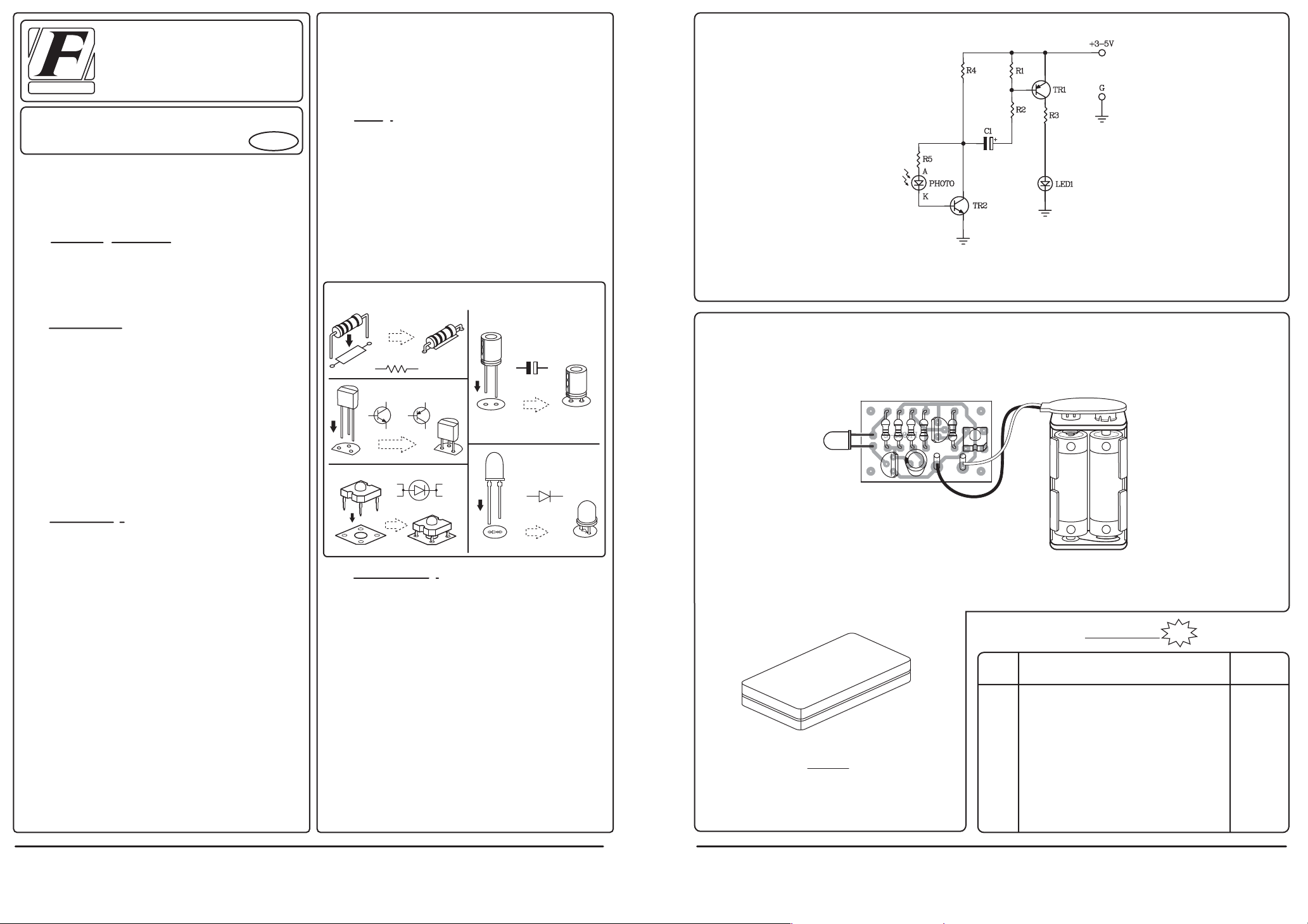
How to works:
When the infrared light into photodiode sensor,
internal resistance of photodiode is low resistance
causing TR2 is working follow the infrared light after
then at the cathode of photodiode will has the voltage.
This voltage is fed to the base of TR1 through C1 which
TR1 will be working when the base of TR1 is equal to
zero volt only. When TR1 is working, at the collector of
TR1 has the voltage causing LED1 is light-on.
PCB assembly:
Shown in Figure 3 is the assembled PCB. Starting
with the lowest height components first, taking care not
to short any tracks or touch the edge connector with
solder. Some tracks run under components, and care
should be taken not to short out these tracks. If the pins
will not enter the holes with ease, use a small drill to
slightly enlarge the opening. All components with axial
leads should be carefully bent to fit the position on the
PCB and then soldered into place. Make sure that the
electrolytic capacitors are inserted the correct way
around. Some components are particularly sensitive to
heat ( ie: Transistors, IC's, diodes etc.) extra care must
be taken to only apply the iron for as little time as
possible, using a pair of pliers to grip the leads will help
HIGH QUALITY ELECTRONIC KITS
CODE 933
LEVEL 1
cutters to prevent excess lengths causing a short circuit.
Now check that you really did mount them all the right
way round!
Testing:
The board should be given a final inspection
before power is applied. Supply the battery 3 to 5V. to
the circuit. With the position pole is connected to "+"
point and the negative pole is connected to "-" point.
After then transmit the infrared light into photodiode.
At LED will be blinking but if stop transmit the
infrared light at LED is stoping blink.
Figure 1. Installing the componants
RESISTOR
R
R
R .....
Ω
TRANSISTOR
TR
NPN
C
B
E
PNP
E
B
C
TR
LED
AA
A
K
LED
LED
Troubleshooting:
The most problem like the fault soldering. Check
all the soldering joint suspicious. If you discover the
short track or the short soldering joint, re-solder at that
point and check other the soldering joint. Check the
position of all component on the PCB. See that there are
no components missing or inserted in the wrong places.
Make sure that all the polarised components have been
soldered the right way round.
K
LED
ELECTROLYTIC
CAPACITOR
+
C .....
µ
F
+
C
Watch the polarity!
PHOTO DIODE
A
PHOTO
K
A
PHOTO
+
C
K
PHOTO
Figure 2. The infrared remote checker circuit
Figure 3. Connections
PHOTO
DIODE
PHOTO
2
1
+
G
FK933-2
POWER SOURCE
1.5Vx2 SIDE AA
NOTE:
FUTURE BOX FB17 is suitable for this kit.
3-5V
A
LED
K
+
BLACK -
CODE
FK
168
169
170
171
172
173
174
816
817
RED +
+
-
1.5V
1.5V
+
-
NEW KIT SET
DESCRIPTION
NO SMOKING FLASHER 46 LED
DANCING ROBOT FLASHER 33 LED
DANGER FLASHER 42 LED
TWO LAMP FLASHER
THREE STEP FLASHER 19 LED
HALLOWEEN PUMPKIN FLASHER 23 LED
5x7 ANIMATED LED SIGNBOARD
VARIABLE REGULATOR 0-50V. 3A.
TRANSFORMERLESS POWER SUPPLY 6-9-12V 50mA
NEW
POWER
9-12VDC.
9-12VDC.
9-12VDC.
3VDC.
9-12VDC.
9-12VDC.
3-5VDC.
50VDC.
220-240VAC.
HIGH QUALITY ELECTRONIC KIT SET FOR HOBBY & EDUCATION
http://www.futurekit.com
 Loading...