

Page 1
MCT-MC 4.3 User Manual
MCT-MC 4.3 User Manual Rev. A
February 2018
Page 2

Safety Information in this Manual
Notes, cautions and warnings appear throughout this book to draw your attention to important operational and
safety information.
A “NOTE” marks a short message to alert you to an important detail.
A “CAUTION” appears with information that is important for protecting your equipment and insuring
performance.
A “WARNING” appears with information that is important for protecting you, others and equipment from
damage. Pay very close attention to all warnings that apply to your application.
This symbol (an exclamation point in a triangle) precedes a general CAUTION or WARNING
statement.
This symbol (a lightning bolt in a lightning bolt in a triangle) precedes an electric shock hazard
CAUTION or WARNING safety statement.
Technical Assistance
If you encounter a problem with your MC controller, review all of your configuration information to verify that
your selections are consistent with your application: inputs; outputs; alarms; limits; etc. If the problem persists
after checking the above, you can get technical assistance by dialing +1 (866) 342-5332 or by faxing your
request to +1 (866) 332-8014, Monday thru Friday, 8:00 a.m. to 5:00 p.m. Eastern Standard Time. You can
also email your request to support@futuredesigncontrols.com.
An applications engineer will discuss your application with you.
Please have the following information available:
• Complete Model #’s and/or Serial #’s for Component(s) in Question
• Complete Software Version #’s
• All Configuration Information
• All User Manuals
Warranty and return information is on the back cover of this manual.
Comments
Your comments or suggestions on this manual are welcome. Please send them to:
Future Design Controls, P.O. Box 1196, Bridgeview, Illinois, 60455
Telephone: +1 (888) 751-5444; fax: +1 (888) 307-8014
csr@futuredesigncontrols.com
The MCT-MC User Manual is copyrighted by Future Design Controls, Inc., © 2018, all rights reserved.
Page 3

MCT-MC 4.3
1 What is the MCT-MC? .................................................................................................. 7
1.1 Features ............................................................................................................................... 7
2 Installation .................................................................................................................... 9
2.1 Enclosure Guidelines ............................................................................................................ 9
2.1.1 Locating the MC Touch Screen Interface ......................................................................................... 9
2.2 Environmental Considerations ............................................................................................ 10
2.3 Mounting Dimensions ......................................................................................................... 10
2.3.1 MC Touch Screen Interface ............................................................................................................ 10
2.3.2 MC Process Loop Controls ............................................................................................................. 12
3 Wiring .......................................................................................................................... 13
3.1 Power Requirements .......................................................................................................... 13
3.1.1 Installing the Power-On Delay Relay .............................................................................................. 13
3.2 Connecting to the MCT-MC Interface ................................................................................. 15
3.2.1 Process Loop Controller Communications ..................................................................................... 16
3.2.2 Connecting to the Process Loop Controls ...................................................................................... 17
3.2.3 User Serial Communications .......................................................................................................... 17
4 Configuring the MCT-MC ........................................................................................... 19
4.1 Control Setup ..................................................................................................................... 21
4.2 Loop Address Utility ............................................................................................................ 21
4.3 Loop Configuration ............................................................................................................. 22
4.3.1 Tagname ......................................................................................................................................... 23
4.3.2 Input Type ....................................................................................................................................... 23
4.3.3 Input Units ....................................................................................................................................... 23
4.3.4 Decimal Point.................................................................................................................................. 24
4.3.5 Input Low/High Scale ...................................................................................................................... 24
4.3.6 Input Filter ....................................................................................................................................... 24
4.3.7 Event Input Function ....................................................................................................................... 24
4.3.8 Event Input Alarm Message ........................................................................................................... 26
4.3.9 Low/High Limit Setpoint .................................................................................................................. 26
4.3.10 Output 1 Function ........................................................................................................................... 26
4.3.11 Output 1 Failure Transfer ............................................................................................................... 27
4.3.12 Output 1 ON-OFF Control Hysteresis ............................................................................................ 27
4.3.13 Output 1 Cycle Time ....................................................................................................................... 27
4.3.14 Output 1 Low/High Limit Values ..................................................................................................... 27
4.3.15 Output 2 Function ........................................................................................................................... 28
4.3.16 Output 2 Failure Transfer ............................................................................................................... 29
4.3.17 Output 2 Low/High Limit Values ..................................................................................................... 29
4.3.18 Output 3 Function ........................................................................................................................... 29
4.3.19 Output 3 Failure Transfer ............................................................................................................... 30
4.3.20 Output 4 Function ........................................................................................................................... 30
4.3.21 Output 4 Failure Transfer ............................................................................................................... 30
4.3.22 Output 4 Low/High Limit Values ..................................................................................................... 31
4.3.23 Output 4 Retransmit Low/High Scale ............................................................................................. 31
4.3.24 Alarm (1-3) Function ....................................................................................................................... 31
4.3.25 Alarm (1-3) Mode ............................................................................................................................ 32
4.3.26 Alarm (1-3) Indication ..................................................................................................................... 33
4.3.27 Alarm (1-3) Setpoint ....................................................................................................................... 33
4.3.28 Alarm (1-3) Hysteresis .................................................................................................................... 34
4.3.29 Setpoint at Start of Automatic Program .......................................................................................... 34
4.3.30 Setpoint at End of Automatic Program ........................................................................................... 35
4.3.31 Power Fail Recovery ...................................................................................................................... 35
Table of Contents - 3 - FDC MC
Page 4

MCT-MC 4.3
4.3.32 Communication Mode ..................................................................................................................... 36
4.3.33 Monitor Only Mode ......................................................................................................................... 37
4.4 Functions ............................................................................................................................ 38
4.5 Startup View ....................................................................................................................... 41
4.6 Alarm Names ...................................................................................................................... 41
4.7 Event Names ...................................................................................................................... 42
4.8 Custom Name\Address ...................................................................................................... 42
5 Basic Operation .......................................................................................................... 43
5.1 OEM Configuration Options ................................................................................................ 43
5.1.1 Loop Control Monitor Only Mode.................................................................................................... 43
5.2 Touch Screen Interface ...................................................................................................... 44
5.3 Menu Navigation ................................................................................................................ 45
5.3.1 Home Menu .................................................................................................................................... 46
5.3.1.1 Text Based Home Menu ......................................................................................................................... 46
5.3.1.2 Icon/Slide Page Based Home Menu ....................................................................................................... 47
5.3.2 Device Settings Menu ..................................................................................................................... 48
5.3.2.1 Text Based System Setup Menu ............................................................................................................ 48
5.3.2.2 Icon/Slide Page Based Device Settings Menu........................................................................................ 49
5.3.3 Offline Menu ................................................................................................................................... 50
5.3.3.1 Text Based Offline Setup Menu .............................................................................................................. 50
5.3.3.2 Icon/Slide Page Based Offline Menu ...................................................................................................... 51
5.3.4 Data Menu ...................................................................................................................................... 52
5.3.4.1 Text Based Data Logging Menu ............................................................................................................. 52
5.3.4.2 Icon/Slide Page Based Log Menu .......................................................................................................... 53
5.4 Notifications ........................................................................................................................ 54
5.5 Control Loops (Single Set point Operation) ........................................................................ 55
5.5.1 Loop View ....................................................................................................................................... 55
5.5.1.1 Historical Minimum and Maximum .......................................................................................................... 56
5.5.1.2 Manual Operation ................................................................................................................................... 57
5.5.1.3 Program Operation ................................................................................................................................. 57
5.5.2 Overview Screen ............................................................................................................................ 58
5.6 Process Monitoring ............................................................................................................. 59
5.6.1 Charts ............................................................................................................................................. 59
5.6.1.1 Chart Setup ............................................................................................................................................ 60
5.7 System Alarms ................................................................................................................... 61
5.7.1 Alarm Monitor ................................................................................................................................. 61
5.7.2 Alarm File ........................................................................................................................................ 62
6 Automatic Ramp/Soak Program Operation ............................................................. 63
6.1 Entering a Ramp/Soak Program ......................................................................................... 64
6.1.1 Setting Step Type ........................................................................................................................... 65
6.1.2 Setting Step Set Point and Time .................................................................................................... 65
6.1.2.1 Ramp/Soak Time Units Selection ........................................................................................................... 66
6.1.3 Setting Step Events ........................................................................................................................ 67
6.1.4 Setting Hold Events ........................................................................................................................ 68
6.1.4.1 HoldBack Limits ...................................................................................................................................... 68
6.1.5 Setting Jump Steps ........................................................................................................................ 69
6.1.6 Setting the End Step ....................................................................................................................... 70
6.2 Starting an Automatic Ramp/Soak Program ....................................................................... 71
6.2.1 Hold/Resume Ramp/Soak Program Operation .............................................................................. 72
6.2.2 Program Mode Settings .................................................................................................................. 72
6.3 Monitoring Automated Ramp/Soak Program Operation ...................................................... 73
6.4 Common Questions About Ramp/Soak Program Operation ............................................... 74
7 Security ....................................................................................................................... 75
FDC MCT-MC - 4 - Table of Contents
Page 5

MCT-MC 4.3
7.1 Adding Users ...................................................................................................................... 76
7.2 Viewing Users .................................................................................................................... 76
7.2.1 New Password Entry ...................................................................................................................... 76
7.3 Setting User Access ........................................................................................................... 77
7.3.1 Security System User Access ........................................................................................................ 77
7.4 Setting Security Options ..................................................................................................... 79
7.5 Audit Trail ........................................................................................................................... 80
8 Data Logging .............................................................................................................. 81
8.1 Selecting Points for Logging ............................................................................................... 82
8.2 Starting/Stopping Data Logging .......................................................................................... 82
8.2.1 Calculating Log File Size ................................................................................................................ 83
8.3 Reviewing Historical Data ................................................................................................... 84
8.3.1 History Plot Setup ........................................................................................................................... 84
8.3.2 Plotting Historical Data ................................................................................................................... 84
8.4 USB File Transfer ............................................................................................................... 86
8.5 FTP/FileWeb/DataWeb Interface ........................................................................................ 88
8.5.1 More About FTP, FileWeb and DataWeb Interfaces ...................................................................... 89
8.5.2 FileWeb/DataWeb Server Components and Requirements. .......................................................... 91
8.6 FDCUtil.com Web site for FTP, FileWeb and DataWeb Testing.......................................... 92
8.7 Annotation .......................................................................................................................... 98
8.8 Add\View Digital Signatures ............................................................................................... 99
9 Device Settings ........................................................................................................ 100
9.1 Tuning .............................................................................................................................. 101
9.1.1 Heat or Cool only P (or PD) Control ............................................................................................. 101
9.1.2 Heat/Cool (Bimodal) Control ......................................................................................................... 102
9.2 Alarms .............................................................................................................................. 102
9.3 Setpoint Limits .................................................................................................................. 103
9.4 Event Names .................................................................................................................... 104
9.5 Navigation ........................................................................................................................ 104
9.6 Communication Settings ................................................................................................... 105
9.7 Email ................................................................................................................................ 106
9.7.1 Email Address Entry ..................................................................................................................... 106
9.7.2 Email Addresses ........................................................................................................................... 106
9.7.3 Email Settings ............................................................................................................................... 107
9.7.4 Email Message ............................................................................................................................. 108
10 Offline ........................................................................................................................ 109
10.1 Power Recovery ............................................................................................................... 110
10.1.1 Recovery Interval .......................................................................................................................... 110
10.2 Degrees C/F Units Selection ............................................................................................ 111
10.3 Clock Settings .................................................................................................................. 111
10.3.1 Time Options ................................................................................................................................ 112
10.3.1.1 Local Time Server Settings................................................................................................................... 112
10.3.2 Daylight Savings ........................................................................................................................... 112
10.4 Language ......................................................................................................................... 113
10.5 Calibration ........................................................................................................................ 114
10.5.1 Loop Calibration Offset ................................................................................................................. 115
10.5.2 Manual (Factory) Calibration ........................................................................................................ 116
10.5.2.1 Thermocouple Input Calibration............................................................................................................ 116
10.5.2.2 RTD and Linear Input Calibration ......................................................................................................... 118
10.6 Display Settings ................................................................................................................ 120
10.6.1 Calibrate Touch ............................................................................................................................ 120
Table of Contents - 5 - FDC MC
Page 6

MCT-MC 4.3
10.6.2 Backlight Settings ......................................................................................................................... 121
10.7 Configuration .................................................................................................................... 122
10.7.1 Importing an OEM Default Configuration ..................................................................................... 123
10.8 About MCT-MC ................................................................................................................ 124
10.9 Exit Application ................................................................................................................. 125
11 Communications ...................................................................................................... 126
11.1 Ethernet Communications ................................................................................................ 126
11.1.1 Guide to Smart Networking Practices .......................................................................................... 126
11.1.2 Configuring the MC Network ........................................................................................................ 127
11.1.2.1 Obtaining the MC MAC Address ........................................................................................................... 127
11.1.2.2 Setting a Static IP Address ................................................................................................................... 129
11.1.3 Using the Web Server .................................................................................................................. 131
11.1.4 Using the VNC Server .................................................................................................................. 133
11.1.4.1 Recommended VNC Viewer Settings (PC/MAC) .................................................................................. 133
11.1.4.2 Recommended VNC Viewer Settings for Tablets ................................................................................. 135
11.1.4.3 Accessing the MC through a VNC Viewer ............................................................................................ 136
11.2 Serial Communications Option ......................................................................................... 138
12 Alarm Codes and Troubleshooting ........................................................................ 139
Appendix .......................................................................................................................... 141
A.1 Communications ............................................................................................................... 141
A.1.1 Explanation of Terms .................................................................................................................... 141
A.1.2 Serial Communications ................................................................................................................. 143
A.1.3 Interface Standards ...................................................................................................................... 144
A.1.4 Interface Converters ..................................................................................................................... 144
A.1.5 Protocol ......................................................................................................................................... 146
A.1.6 Creating Your Own Modbus Application ...................................................................................... 148
A.1.7 Packet Syntax ............................................................................................................................... 149
A.1.8 Error Checking .............................................................................................................................. 152
A.1.9 Transmitting and Receiving Messages ........................................................................................ 153
A.1.10 MCT-MC Loop Control Data Registers ........................................................................................ 155
A.1.10.1 Control Registers.................................................................................................................. 156
A.1.10.2 Automatic Program Registers .............................................................................................. 159
A.1.10.3 Starting an Automatic Program ............................................................................................ 162
A.2 FTP, FileWeb, DataWeb Requirements/Installation .......................................................... 164
A.2.1 Introduction ................................................................................................................................... 164
A.2.2 System Overview .......................................................................................................................... 164
A.2.3 System Requirements .................................................................................................................. 164
A.2.4 MySQL Installation ....................................................................................................................... 164
A.2.5 Website Installation ...................................................................................................................... 164
A.2.6 Data Transfer Service Installation ................................................................................................ 165
A.2.7 HTTP vs HTTPS ........................................................................................................................... 165
A.2.8 FTP Server ................................................................................................................................... 165
A.2.9 File Transfer Service Configuration (FileWeb) ............................................................................. 166
A.2.10 Database Transfer Service Configuration (DataWeb) .................................................................. 167
A.2.11 Database Field Map ..................................................................................................................... 167
A.3 Profile Recovery Detail ..................................................................................................... 170
A.4 Touch Screen Interface Specifications.............................................................................. 172
A.5 Power Supply Specifications ............................................................................................ 175
A.6 Power-On Delay Relay Specifications .............................................................................. 179
A.7 Ordering Specifications .................................................................................................... 181
A.8 Support and Warranty Information .................................................................................... 184
FDC MCT-MC - 6 - Table of Contents
Page 7

MCT-MC 4.3
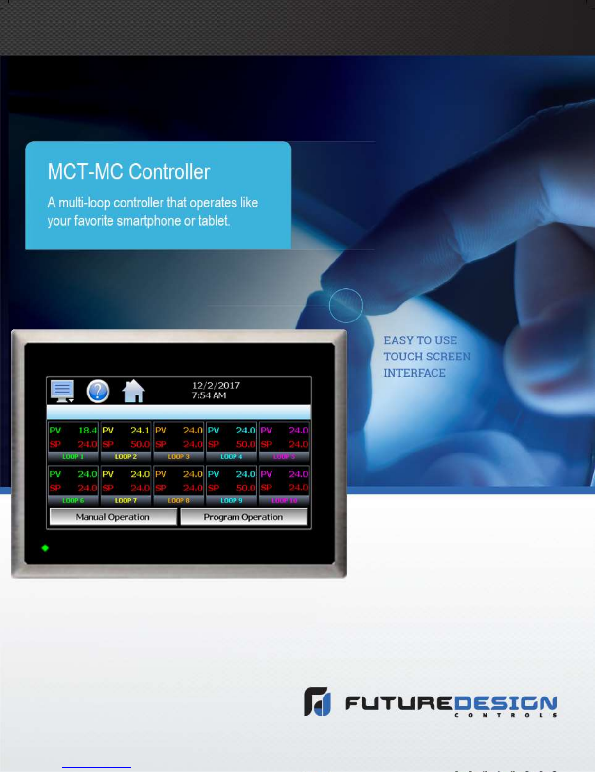
1 What is the MCT-MC?
The MCT-MC system combines all of the features of a loop controller, video/chart recorder and data logging
system into a single/intuitive display device. Email (supporting SSL/TLS), SMS (text messaging), FTP,
FileWeb, DataWeb (file transfer protocols for automated data backup and web database interface) and remote
viewing/control (via Web server/VNC server) are standard with the MC and can be accessed via LAN/WAN
using a PC, tablet or smart phone device.
Future Design Controls’ “MC” provides a 4.3” color touch screen interface with standard “Smart Device” user
interface features for multi-loop OEM control applications. All loop configuration and runtime user access is
configurable at the device with no PC software required. OEM’s have the ability to configure runtime features
(screen availability, menus, language, etc...) to easily customize the system for their requirements. These
configurations can be imported/exported to any other MC device for setup (from scratch) within minutes.
Individual high performance board level PID loop controls (one for each loop up to a maximum of 10) offer up
to four control outputs each, powerful profiling capabilities with up to three events and full auto tune functionality
with high resolution universal process inputs.
1.1 Features
Each of the MC loop control boards provide a single digital input that can be programmed as an automatic
program control input, input alarm or input status (visual loop status indication).
Each of the loop control boards also provide up to four control outputs which can be used as PID control outputs
for heat/cool, direct outputs for controlling external equipment related to the application through software
switches called events, or be programmed to act as system alarm outputs.
The MC can be operated in single set point or automatic program control mode. Program entry is made easy
through the use slide list selections and menu items on a single entry screen. Programs can be copied to the
external USB memory stick and then imported to another MC controller which eliminates the need to enter
duplicate programs on multiple systems.
Data file analysis tools make looking at historical data a simple task. Any control variable saved to the data file
can be plotted on the historical data chart for any time frame within the data file’s total time range.
The built in Ethernet functionality includes a Web Server to provides access to all MC data (view only), a VNC
interface for remote control and monitoring and an NTS clock, all available via a local Intranet connection (wired
or wireless), or the World Wide Web using standard software like Microsoft’s Internet Explorer.
The MC provides a rich set of tools for control interaction and process monitoring. The interface provides
various loop, chart, alarm, automated program status as well as historical data, alarm log and audit trail views.
The menu driven interface eliminates screen “clutter” by providing an easy to use “Smart Device” interface for
interaction between the user and MC.
The MC can store over a years worth of data on its SD memory card. Data logging can be enabled manually
or automatically during program operation. Data backup is provided via a USB memory stick for plug and play
transfer of files to any PC and through the included FTP back-up utility.
The MC protects system access with a four level security system (user rights based), including audit trail
capability that documents all user activity and ensures data integrity by digitally signing all data files and audit
trails to meet regulatory requirements.
What is the MCT-MC - 7 - FDC MCT-MC
Page 8

MCT-MC 4.3
The MCT-MC controller includes the following features:
ACCESSIBILITY
Touch screen, “Smart Device” user interface (UI) with
30,000 hour LED display
Built in configuration software; no external software or
PC required
Email, SMS, FTP, FileWeb, DataWeb, VNC and Web
functionality standard
Remote View/Control using PC, Tablet or Smartphone.
National time server connectivity with daylight savings.
COMMAND BAR ICONS
NAVIGATION, HELP & HOME
The Master Command Bar located on the top of the
display provides easy & intuitive 1-touch access from
anywhere in the system to Navigation, Help and
configured Home view.
Home brings the user back to the system “Home” view.
The Home icon can be configured for the following
standard views:
Loop view: includes PV & SP digital display, PV
min/max, PID % Output, Auto-Manual, event, profile
access and more.
Overview: all loops, profile and event status
Chart view: (trend up to the last 24 hours from system
RAM) supporting 4 trends with up to 8 values per trend
Alarm view or Alarm File
Help offers content sensitive text for every view / page
in one of 11 supported languages chosen by the user.
Navigation provides access to the configured menu
system, traditional drop down or icon.
SECURITY AND AUDIT TRAIL
• Supports up to 30 users over four user groups with
access to 40+ functions restricted by user group.
• Supports password aging and verification.
• Operator Audit Trail provides history for all user activity
that includes date, time, user name and action; i.e. Loop
SP change from 55.2 to 103.5.
PROFILE RAMP/SOAK
• Individual operation per loop or set point generator
(one loop runs profile and other loop set points
automatically set to follow master loop)
• Start: via touch screen or Event input
• Profile Name: 16 character naming convention
• Global Profile Configuration:
- Start from PV or static SP
- Guaranteed Soak & Ramp band
- Power Fail / Recovery: Continue from last SP value,
PV or static mode.
• Profile Segments: (maximum of 64)
• Guaranteed Soak & Ramp per step
• Events: up to 3 per step (based on loop configuration).
• Jump-To Step: configurable per step
• Profile End Alarm
• Configurable Profile End Logic:
- Current (Static) Control SP: Set Point & Event
status prior to Profile Start is loaded at end of the
Profile.
- Final SP of Profile with all Events off
ALARMS
• Up to 30 alarms configurable to B42 (up to 3 alarm
outputs per B42).
• Loop* Alarm Types: Process High & Low, Deviation High
& Low, Deviation Band, Event Input and End of Profile.
* B42 configured as Monitor Input (no PID control)
configurable only with Process alarms.
Alarm Mode:
Normal or Hold (on start-up Hold mode will not
activate if in alarm condition and arm once out of
alarm condition).
Silent Alarm, activation does not indicate alarm or
write to alarm log file.
Alarm outputs configurable as latching or nonlatching.
DATA ACQUISITION
• Data log PV, SP and PID percent output.
• File name: Free form 16 character appended by
time/date or the profile name if started with a profile.
• File Start/Stop: user on-demand, on system boot or
profile ramp-soak start/end.
• Data Log interval: configurable 1 second to 31 minutes.
• File Interval: configurable to set time in days (1 to 31) to
end and start a new file. This allows syncing files to
match product cycles as well as keeping file size
manageable.
• ID#1 and ID#2 fields allow user to enter specific
information such as a batch and/or lot information that is
associated with the data file.
• Operator Comments/Events: Unlimited operator
comments/events linked to each file
• File Type: Data Log fi les are saved in .csv format.
• Digital Signatures: Automatic system as well as user
entered signatures.
• Historical Data Viewer: View data log fi les on the display.
Chart is auto-scaled on an X & Y axis for time and units.
• Meets the requirements for:
- CFR21 Part 11
- AMS2750E
EVENT INPUTS
• B42 each have 1 event input configurable for one of the
following functions.
- Profile Run
- Hold
- Run/Hold
- Abor
- Step Advance
- Failure Transfer (Outputs)
- Alarm Input (indication only)
- Loop Status Input
FDC MCT-MC - 8 - What is the MCT-MC
Page 9
MCT-MC 4.3
2 Installation
All MC components are pre-loaded with all operating software and firmware before leaving the factory so it is
ready to install when you receive it. Before beginning installation, completely read through this section as well
as the following section (3. Power and W iring) to gain an understanding of the entire installation process.
Consider the installation carefully. Plan the power, signal and control wiring before installing the MC. Also
consider the cabinet space, hardware dimensions, environmental conditions and use good wiring practices to
minimize problems that may occur due to electrical interference.
To avoid potential electric shock and other hazards, all mounting and
WARNING:
Special expertise is required to install, wire, configure and operate the
Prevent metal fragments and pieces of wire from dropping inside the
CAUTION:
When handling the B42 series loop control boards, use proper ESD
Locate the MC and all related control components away from AC
2.1 Enclosure Guidelines
wiring for the MC must conform to the National Electric Code (NEC)
and other locally applicable codes.
MC controller. Personnel without such expertise should not install, wire
or operate the MC.
housing of any MC component. If necessary, place a cover over the
components during installation and wiring. Ingress of such fragments
and chips may cause a fire hazard, damage or malfunction of the
device.
(electro-static discharge) handling procedures to prevent damage to
board components.
power/motor wiring and sources of direct heat output such as
transformers, heaters or large capacity resistors.
The MC must be installed correctly for reliable operation. The MC controller is designed for installation within
a suitable enclosure. Do not install the MC outside of an enclosure. Care must be taken when locating
components to ensure that AC power wiring, contactors, starters, relays and other sources of electrical
interference are properly located to minimize their impact on the MC control system.
Particular note should be taken to the position of variable speed drives and switching power supplies. Their
input and load cables should be screened and properly grounded to a central equipment grounding point to
prevent radiated emissions from affecting MC operation.
2.1.1 Locating the MC Touch Screen Interface
It is recommended that the unit be mounted within the front panel of a steel enclosure, through an appropriately
sized opening. Proper enclosure depth is required to insure that there is adequate spacing between the rear
of the interface and the front of any high voltage devices mounted in the enclosure when the enclosure door is
closed. It is required that a minimum separation of 2” be maintained, so plan a depth to accommodate at least
4” (102mm) behind the front of the panel.
Installation - 9 - FDC MCT-MC
Page 10
MCT-MC 4.3
Proper clearance must also be maintained above, below and on both sides of the interface to allow for heat
dissipation and to facilitate mounting. A minimum of 2” is recommended. Note that additional space may be
required below and to the right of the interface (looking from rear of unit) to accommodate the communications
wiring depending upon the type of communication cables used.
2.2 Environmental Considerations
Do not subject the MC touch screen interface to operating temperatures below 0°C (32°F) or above 50°C
(122°F). The operating temperature for the P41/B42 loop controls is limited from -10°C (14°F) to 50°C (122°F).
Minimum and maximum relative humidity levels are limited between 10% and 90% (non-condensing) for the
touch screen and 0 to 90% for the loop controls. The MC touch screen interface is to be used indoors only.
The unit should not be installed where fast temperature variations may occur as this can cause condensation
of water vapor on the device.
The MC should not be exposed to excessive dust, dirt, salt, direct sunlight or shock and vibration. Do not
operate the MC controller in an area where chemicals or flammable gases are present. Permitted storage
temperature extremes for the MC control system are limited to -10°C (14°F) and 60°C (140°F) for the touch
screen and -40°C (-40°F) and 60°C (140°F) for the loop controls.
2.3 Mounting Dimensions
Note that your system may not include some of these components, and that quantities of certain components
vary depending upon the application and options ordered. Make sure that you have all components required
for your application prior to installation.
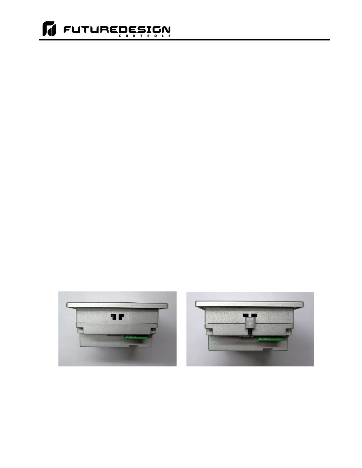
2.3.1 MC Touch Screen Interface
The MC 4.3 interface is supplied with four mounting clips. All four clips must be installed and properly tightened
to insure the IP65 protective rating. Failure to install all mounting clips may also affect touch screen operation.
Be sure to tighten each one evenly so as not to flex the case of the unit. DO NOT over tighten the mounting
clips. The clips should be tightened just enough to fully compress the gasket so that the bezel around the
interface is parallel with the mounting surface.
Mounting Clip Slot (4 total) Mounting Clip Installed in Slot
NOTE: The MC will not operate properly without the SD card installed into the SD card slot on the back of
the unit. The SD card has all software required, loaded onto the card for ‘Auto-Boot’ operation. The
slot on the back of the interface is ‘keyed’ so the card can only be installed in one direction. The card
is pre-installed for your convenience. If the card is removed, take care when inserting the SD card
and DO NOT force it into the slot. The card MUST be installed prior to application of power.
FDC MCT-MC - 10 - Installation
Page 11
MCT-MC 4.3
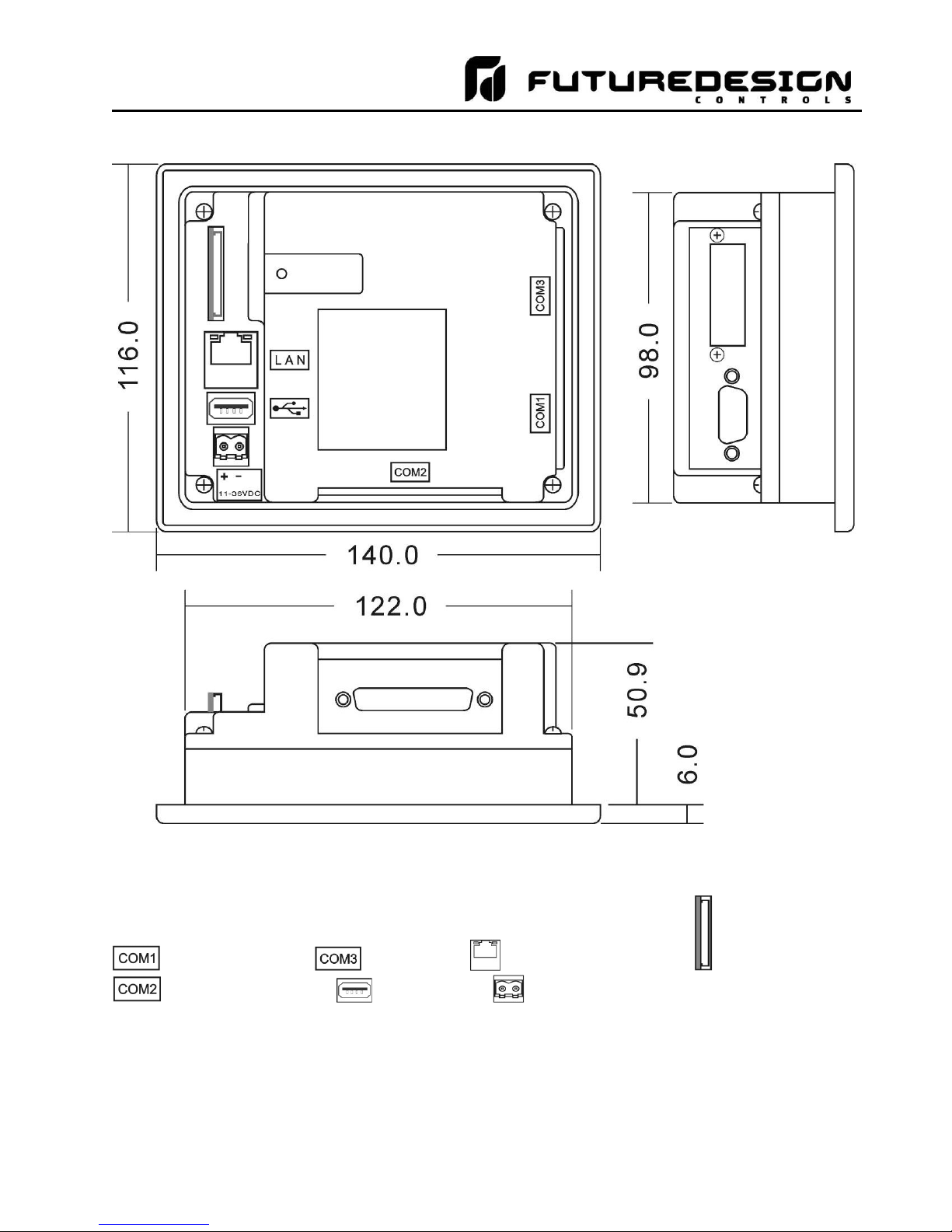
All dimensions are in mm. Tolerance +/- 1 mm.
Panel cutout: 123+1 x 99+1
DB9, Male Not Used LAN, Ethernet (RJ45) SD slot
DB25, Female USB port Power supply
Installation - 11 - FDC MCT-MC
Page 12

MCT-MC 4.3
2.3.2 MC Process Loop Controls
One PID loop control is required for each process control loop in the system. The MC is compatible with both
the Future Design Controls P41, ¼ DIN control and the B42 board level control. Refer to the FDC controller
manual for the model of loop control being used for dimensions, appropriate mounting and installation
instructions.
For applications requiring frequent access to the process controllers, the panel mounted P41 series provides
direct access to the controllers. For applications where operator access to the controls is not required, or is
desired to be kept at a minimum, the B42 loop controls can be mounted directly inside of an enclosure. This
also reduces wiring concerns by eliminating the need to run the sensor, communication and control wiring for
each control to and from an enclosure door.
NOTE: The MC requires firmware version V.22 or later in the P41/B42 loop control for proper manual event
operation. Early model controls can be used, but the manual event control will not function. Only
automatic ramp/soak program event control will be available.
FDC MCT-MC - 12 - Installation
Page 13
MCT-MC 4.3
3 Wiring
This section describes the methods and precautions for wiring the MC system components.
Turn off power to the MC before starting installation, removal, wiring,
WARNING:
Emergency stop and interlocking circuits MUST be configured outside
This section presents recommended installation practices and
CAUTION:
Electrical interference in an operator interface can lead to equipment
maintenance and inspection of the MC controller. Failure to turn off
power may cause electric shock, create a fire hazard or cause damage
to the MC.
of the MC control system. If such circuits are made through the MC,
failure of the MC control system may cause uncontrollable operation,
damage to equipment or accidents.
procedures. Since no two applications are identical, these
recommendations should be considered as guidelines. The system
designer should be aware that devices in control systems could fail and
thereby create an unsafe condition.
start-up, which could result in property damage and/or physical injury
to the equipment operator.
If the application requires an operator or attendant, you should be
aware that this potential safety hazard exists and take appropriate
precautions. Consult NEMA ICS 3-304 for more information regarding
safety for the installation of solid-state programmable control devices.
3.1 Power Requirements
The MC control system touch screen operates on a nominal 24Vdc supply voltage with an allowable range of
11 to 36Vdc. The P41/B42 loop controls can be ordered to operate from either a DC (11-26Vdc) or an AC (90250Vac) supply. Do not power the MC controller components and highly inductive DC loads or input circuitry
to other equipment with the same DC power supply used for the MC.
If the MC is installed in an area with poor power quality or frequent power interruptions, it is recommended that
a time delay-on relay be installed in the power supply wiring to all components of the MC. This will prevent
rapid on-off cycling of the MC during brown-out or momentary power interruptions. Rapid power cycling to MC
can cause damage to the electronics and/or loss of data.
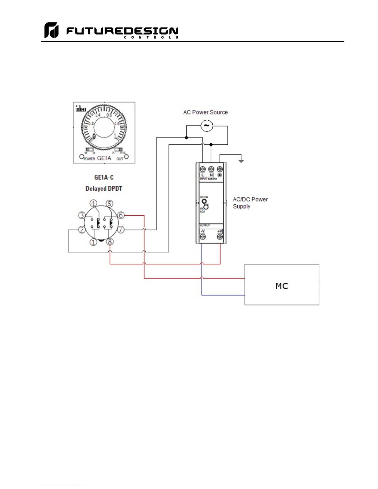
3.1.1 Installing the Power-On Delay Relay
Due to the rate at which AC/DC power supplies reach their nominal supply voltage after application of power,
the relay contact of the timer should be installed between the output of the power supply and the power input
of the MC control system components. This allows the power supply output voltage to reach its nominal value
prior to connecting the MC to its output terminals.
Wiring - 13 - FDC MCT-MC
Page 14
MCT-MC 4.3
In order to properly sense the loss of power, the time delay relay coil should be wired to the AC power source
for the DC power supply of the MC. This will insure that the MC is turned off/on at the proper times and prevent
malfunction that can be caused by rising or falling voltage at the power supply output during power interruption.
NOTE: It is recommended that the time delay-on relay be set for a minimum period of 3 seconds.
FDC MCT-MC - 14 - Wiring
Page 15
MCT-MC 4.3
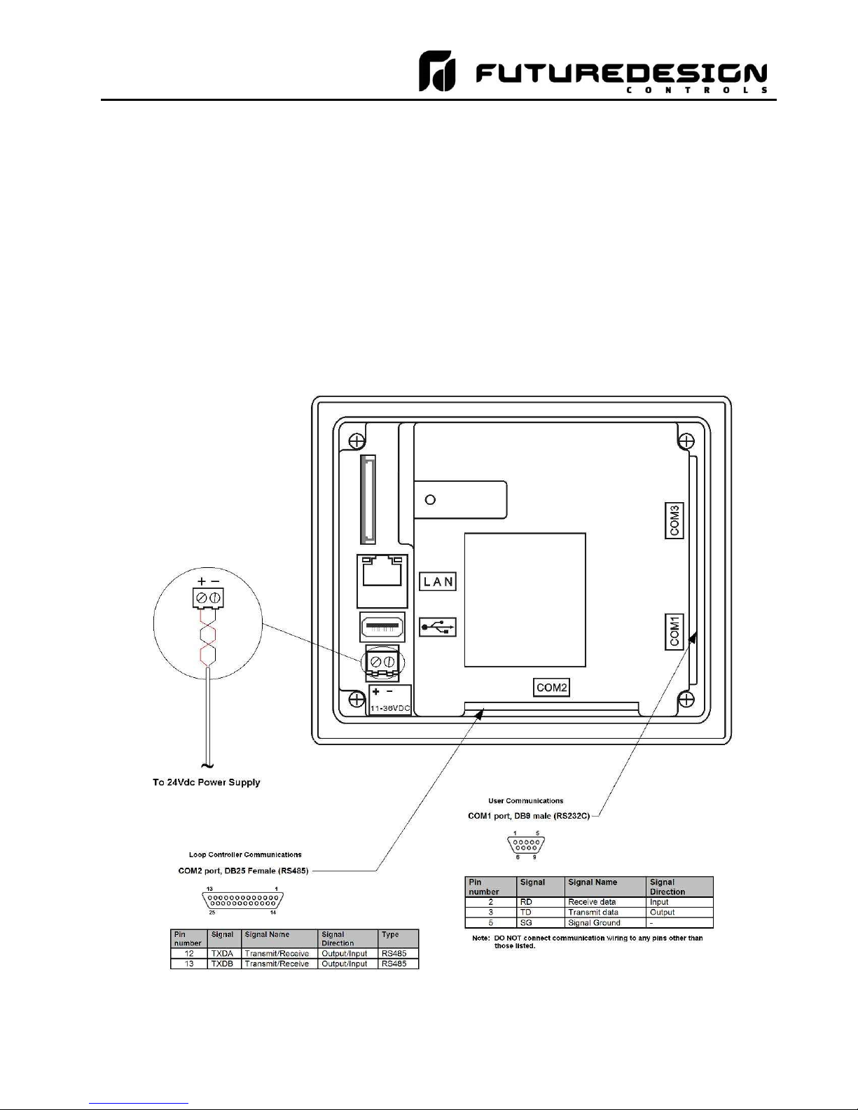
3.2 Connecting to the MCT-MC Interface
Power wiring lengths should be kept to a minimum, and it is preferable to have the power wiring run using a
minimum of 18/2 twisted shielded cable. This keeps the “hot” and “common” wires paired to minimize the
effects of external noise.
To make a connection, strip about ¼” of insulation off the end of the wire, turn the connector screw
counterclockwise until the gap is wide open, insert the wire all the way in, and turn the screw clockwise until it’s
tight. Connect positive DC line (hot) to the ‘+’ terminal and the negative DC line (common) to the ‘-’ terminal.
The other end of the cable should be properly terminated at the 24Vdc power source, and the shield connected
to the main earth ground.
NOTE: Upon application of power, if the display does not come on within 2 seconds, remove power. The
interface is reverse polarity protected. Check wiring to insure proper connections and try to power up
again. An Internal fuse will prevent damage for over voltage conditions; however, it isn’t guaranteed.
DC voltage sources should provide proper isolation from main AC power and similar hazards.
Wiring - 15 - FDC MCT-MC
Page 16
MCT-MC 4.3
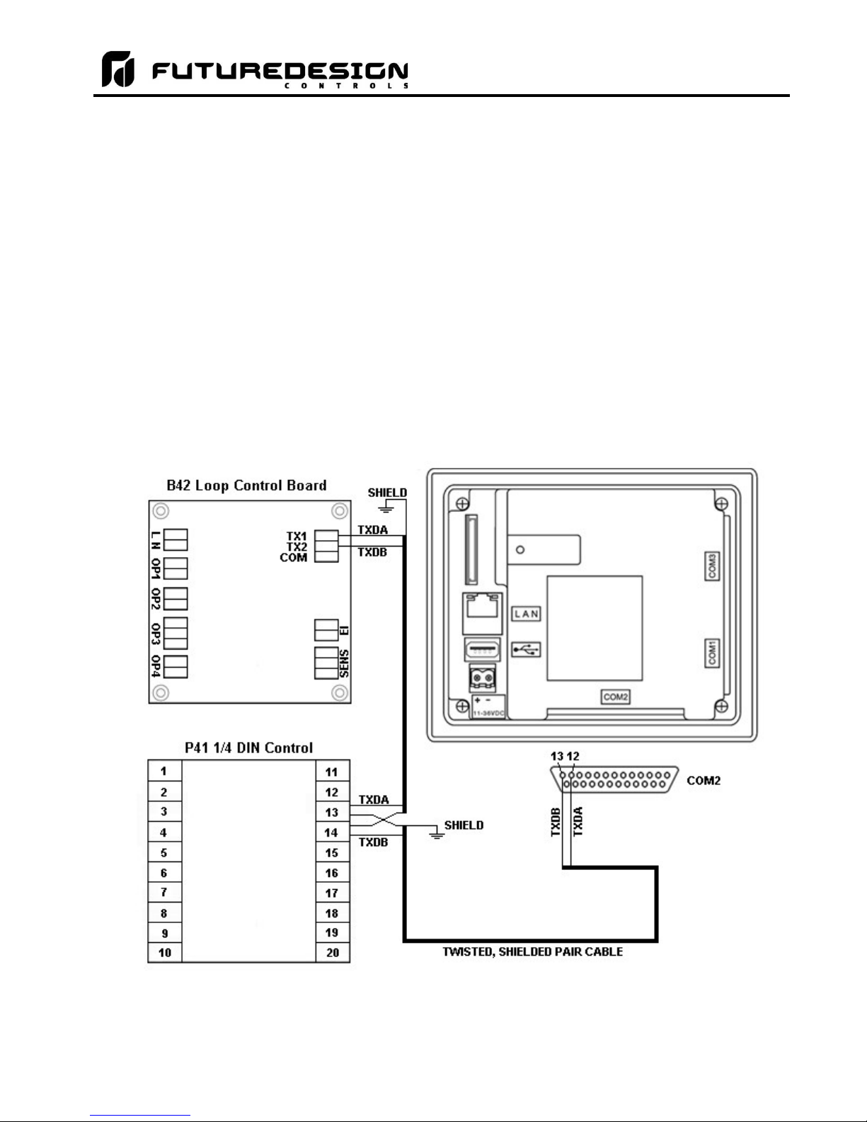
3.2.1 Process Loop Controller Communications
The loop controls communicate with the MC touch screen using the RS485 communications port. This allows
up to ten P41/B42 boards to be connected using one 2-wire link. The controllers are wired in parallel with each
one having their own communications address of 1 through 10 (corresponding to loops 1 through 10).
Communication wiring should be run using a minimum of 24 AWG twisted-pair, copper conductors. For short
runs (< 10 feet total), non-shielded wiring can be used as long as proper separation from power/control
conductors is maintained. For communications wiring where the total length will exceed 10 feet, shielded
twisted-pair should be used.
NOTE: It is important to keep the power/control and sensor/communications wiring separated from one
another. Relay and/or high voltage outputs can interfere with the sensor and communication wiring
as they cycle on and off, which can cause erroneous sensor readings or communications errors.
FDC recommends the use of shielded wire for all installations in order to maintain optimum
performance and minimize the possibility of communications errors.
When using shielded twisted-pair, be sure to ground only one end of the cable, preferably at the loop controller.
Allowing any other portion of the cable shield to come in contact with ground, or grounding both ends, will cause
ground loop currents to flow in that section of the cable shield which can disrupt communications.
FDC MCT-MC - 16 - Wiring
Page 17
MCT-MC 4.3
3.2.2 Connecting to the Process Loop Controls
The MC is compatible with both the Future Design Controls P41, ¼ DIN control and B42 board level process
loop controls. The input and output wiring to the individual loop(s) is dependant upon options ordered on each
device as well as the intended application. For detailed information on input and output wiring, refer to the user
manual for the type of control used.
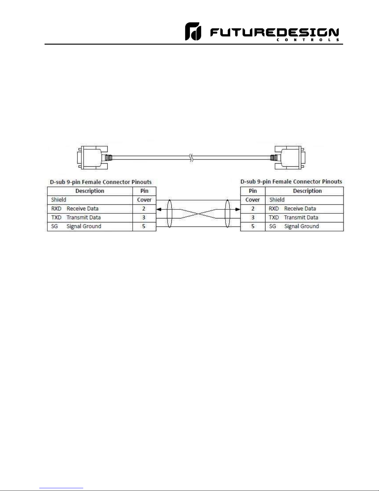
3.2.3 User Serial Communications
The MC touch screen provides an RS232C user communications port for connecting the MC to a PC running
software such as Future Design Control’s Envision software. In order to connect the MC to a PC, a cable must
be fashioned according to the diagram below.
NOTE: DO NOT use a standard null-modem cable to connect the MC to a PC. Most computers do not
provide a standard serial port and a USB to serial converter must be used. Incompatibilities may exist
between the MC and certain USB to serial adapters which may cause the MC to malfunction when
connected using a standard null-modem cable.
If more than one MC controller is to be placed on the communication link with a PC, an RS232/485 converter
is required for each MC in order to convert the RS232 communications port to a RS485 multi-drop
communications for connecting multiple MC controls on the same PC communications link.
Wiring - 17 - FDC MCT-MC
Page 18

MCT-MC 4.3
NOTE: The connection requires a single twisted-pair cable that is daisy-chained from one MC to the next.
When using shielded twisted-pair cable, be sure to ground only one end of the cable, preferably at the
RS232 to RS485 network adapter. Allowing any other portion of the cable shield to come in contact
with ground, or grounding both ends, will cause ground loop currents to flow in that section of the cable
which can cause communication errors.
FDC MCT-MC - 18 - Wiring
Page 19

MCT-MC 4.3
4 Configuring the MCT-MC
IMPORTANT: Once all configuration settings are made, you must select “Exit” from the File menu to exit the
Cconfigurator prior to cycling power to the MC. All configuration files are written upon exiting
the Configurator. Do not cycle power prior to exiting the Configurator or settings will be lost
and the MC will not operate properly once the runtime application starts.
The MC Configurator is a powerful tool that is built in to the system. It is a program that allows the OEM or user
to set up control system options for the MC runtime application. This allows for on-the-spot setup of the MC
without the need for external hardware and software. The user or OEM must first run the Configurator prior to
putting the MC into service in order to properly setup the system for its intended use.
The Configurator program does not run at the same time as the main runtime software. It can be run by exiting
the runtime software via the Offline Setup\Exit Application screen. When the “Exit application (configuration
mode startup)” option is selected, on the next power-up, the Configurator application will automatically start.
From the Configurator, the user or OEM can then setup all process loop controls as well as choose from a long
list of standard features to provide in the runtime application. During setup, the output control functions of each
device can be changed, so any equipment being controlled by the outputs should be placed in an “off” state, so
that any modifications to output functions will not cause an unsafe condition or damage to equipment.
NOTE: On exit of the MC Configurator application, the MC runtime application will automatically run on the
next power-up.
The MC Configurator provides the following functionality:
Set the number of control loops that the system will use (one to ten).
Provide control loop configuration settings for input type, output function, set point range, etc.
‘Splash Screen’ name editing for custom OEM or user requirements
Enable/disable options for runtime menu and screen availability
Text editing for all system event and alarm names
The Configurator menu is accessed by pressing the “Monitor” icon at the top left of the screen.
Configuring the MCT-MC - 19 - FDC MCT-MC
Page 20
MCT-MC 4.3
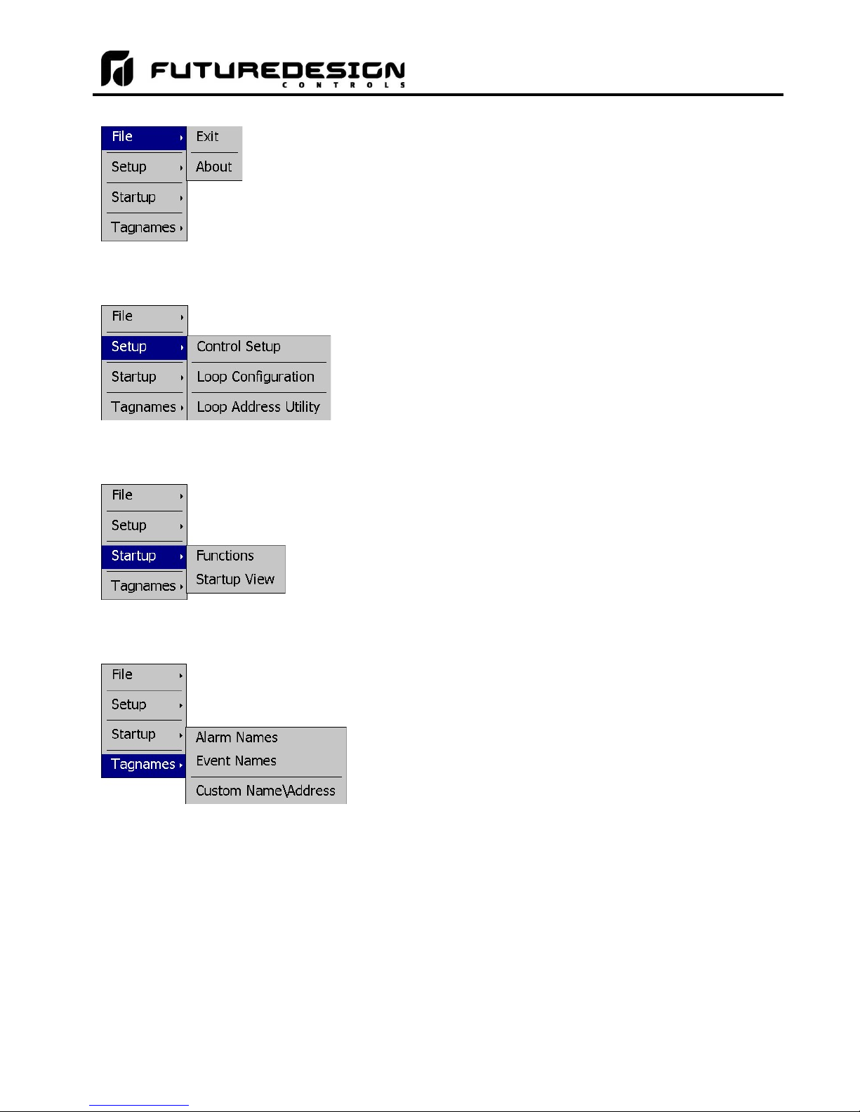
The File menu provides selections of “Exit” and “About”. The exit
function for the Configurator saves all settings and closes the
Configurator application.
The about selection displays version information for the
Configurator application and configured control devices.
The Setup menu provides access to the primary controller setup
options. These options include the controller setup (number of
loops), the loop control board configuration settings and the loop
address utility that can be used to automatically assign the
proper communications address to an attached loop control
board.
The Startup menu provides access to enable and disable
runtime screens/menus and set the desired startup view
selection.
The Tagnames menu provides access to the text editing
functions of the Configurator which allow the event and alarm
names to be changed to match their use in the system. The
menu also provides access to edit the splash screen information
that is shown when the runtime application starts.
FDC MCT-MC - 20 - Configuring the MCT-MC
Page 21
MCT-MC 4.3
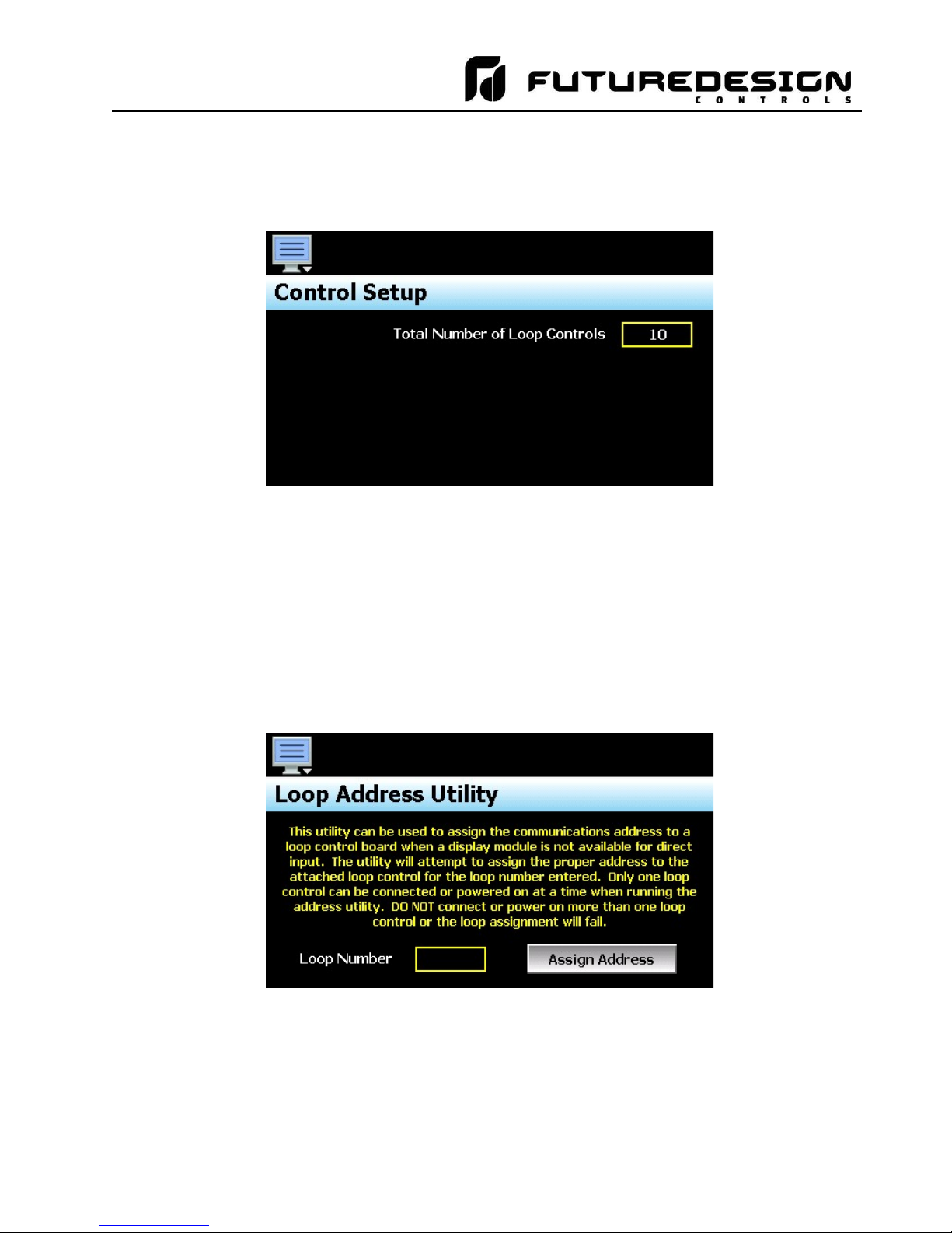
4.1 Control Setup
The “Control Setup” screen is accessed from the Setup menu. It allows the user or OEM to set the number of
control boards that are attached to the system. Once set, the loop configuration settings will be made available
for the total number of loops entered.
4.2 Loop Address Utility
In order for the MC to properly communicate with each of the loop control boards, they must be configured for
the proper communications address. The factory default communication settings of the loop control boards are
set for a communications address of one, which correspond to the proper settings for loop 1. For a single loop
MC control system, no further settings are required. Simply connect the communications wiring between the
control board and the MC interface, and the system is ready to go.
For a multi-loop control system, the other loop control board(s) must be set for an address that corresponds
with the loop number, i.e., 2, 3, 4…. If a display module is not available to connect to the loop control board in
order to set its address, the Loop Address Utility can be used. It is accessed from the Setup menu.
In order to use the utility, only one loop control board can be connected to the MC touch screen display at a
time. Since the default address of all control boards is 1, if more than one was connected, they would all
respond to the same command which would cause them all to be set to the entered address. If more than one
loop control board is connected, disconnect the communications wiring from the loop control board(s) that you
DO NOT want to set the address on. An alternative is to remove power from the loop control board rather than
disconnecting the communications wiring.
Configuring the MCT-MC - 21 - FDC MCT-MC
Page 22
MCT-MC 4.3
With only one loop control board powered on or connected to the MC via the communications link, press the
Loop Number field and enter the address to assign to the attached loop control. Once entered, press the
“Assign Address” button and the utility will begin scanning for the loop control board and set its address to the
one entered once found. If the utility fails to set the address, check the wiring to insure it is properly connected.
If the loop control board has been previously used for another application, it may be possible that the address
or other communications settings have been changed, which prevent the utility from working. In this case, a
display module must be connected to the loop control board to set the proper communications settings:
Address: 1 to 10 (for loop 1 to 10)
Baud rate: 9600
Parity: Even
IMPORTANT: The loop input number corresponds to the communications address that must be set in the
loop control board for the MC to access it properly. If the communications address is not set
properly in the loop control, the MC will not be able to communicate with it, or may communicate
with the wrong loop control and assign incorrect values for the loop.
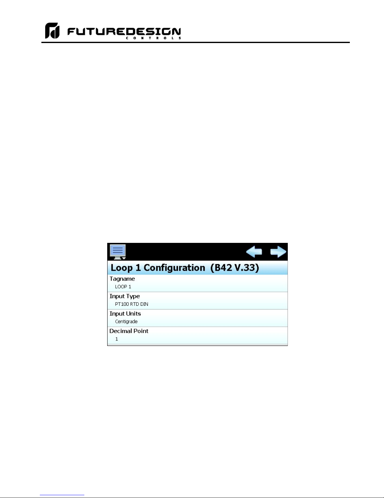
4.3 Loop Configuration
The Loop Configuration screen is accessed from the Setup menu. The screen provides access to all loop
control board settings. When more than one loop is configured, the left/right scroll buttons will be provided at
the top right of the screen. These buttons are used to scroll through all available loop controls in order to
view/edit settings for each.
The model and version of the loop control attached will be shown in the scroll list header. To view all of the
available settings, simply swipe up or down on the screen to scroll through the list items. To edit a value, tap
the row for the desired item. If the entry is a simple numeric value, the number entry pad will be shown. If the
item has multiple selections to choose from, a list of individual selections for the item will be shown.
IMPORTANT: Care should be taken when configuring loop controls as automatic ramp/soak programs may
be downloaded to any loop configured in the system. Each loop should be configured with the
appropriate settings to insure the ramp/soak programs operate properly. Typically all loops,
with the exception of communication address, are configured identically. This especially
applies to the automatic ramp/soak program global settings.
- Setpoint at start of automatic program (section 4.3.29)
- Setpoint at end of automatic program (section 4.3.30)
- Power Fail Recovery (section 4.3.31)
FDC MCT-MC - 22 - Configuring the MCT-MC
Page 23
MCT-MC 4.3
4.3.1 Tagname
The Tagname entry allows the user or OEM to assign a specific name for each control loop, up to 11 characters
in length. This name will be used throughout the MC runtime application and can be used to provide a more
detailed description as to the function the loop provides. Default tag names are LOOP 1 through LOOP 10.
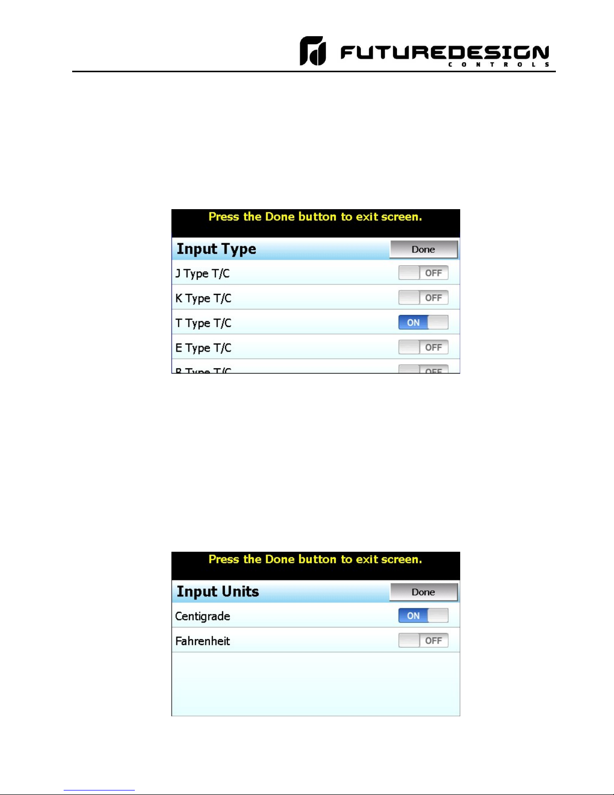
4.3.2 Input Type
The Input Type entry is used to select the type of sensor that will be connected to the loop control. The input
type can be a temperature input (thermocouple or RTD) or a linear input type (Vdc or mA).
The input type selections are mutually exclusive, i.e., selecting one input will turn all other selections off. Once
the desired input type has been selected, press the “Done” button to set the input type for the loop control board
and return to the main Loop Configuration screen.
NOTE: The loop control board is ordered with either a standard input for thermocouples and RTD’s, a voltage
input or a milliamp input. The selected input type must be set to match the type of input supplied on
the loop control board or the unit will not operate correctly.
4.3.3 Input Units
The Input Units entry is used to select the temperature units for temperature input types (thermocouple or RTD).
If the selected input type for the loop is a linear input (Vdc or mA), the Input Units entry will display the text entry
keypad allowing the user or OEM to enter specific engineering units up to 4 characters.
Configuring the MCT-MC - 23 - FDC MCT-MC
Page 24
MCT-MC 4.3
The input unit selections for temperature are mutually exclusive, i.e., selecting one will turn off the other. Once
the desired temperature units have been selected, press the “Done” button to set the input units for the loop
control board and return to the main Loop Configuration screen.
4.3.4 Decimal Point
The Decimal Point entry allows the input precision to be adjusted between 0 and 1 decimal digits for temperature
input types, between 0 and 2 for a 0-60mV input and from 0 to 3 for Vdc and mA input types.
IMPORTANT: Once the loop control board has been configured with a specific decimal point, changing the
decimal point will require the loop control board to be reconfigured in order to maintain previous
control settings. Automatic programs, alarm set points, set point limits, input low/high scale,
etc., DO NOT automatically scale. An entry of 100.0 becomes 1000 when changing the
decimal point to zero (not 100), and must be re-entered to set the proper value.
4.3.5 Input Low/High Scale
The Input Low Scale and Input High Scale entries are used to set the input range for linear input types (Vdc or
mA). The entries are not available for temperature input types since they utilize a fixed range based on the
sensor type. The input low scale value can be set from -32768 up to the high scale value minus 50. The high
scale value can be set from the low scale value plus 50 up to 32767.
NOTE: The minimum and maximum scale values are limited by the decimal point selection. For a decimal
of 0, the values are -32768 and 32767 respectively. For one decimal point, the values are -3276.8
and 3276.7. For two decimal digits, the values are -327.68 and 327.67 and for three decimal digits
the values are -32.768 and 37.767.
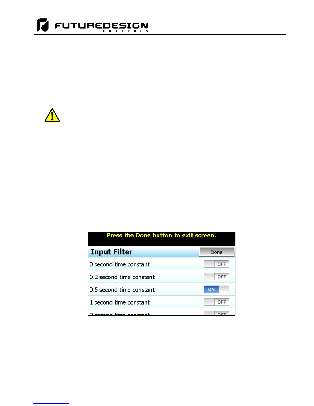
4.3.6 Input Filter
The Input Filter entry is used to select the time constant used for filtering the process input.
The time constant selections are mutually exclusive, i.e., selecting one will turn off the others. Once the desired
filter constant has been selected, press the “Done” button to set the input filter for the loop control board and
return to the main Loop Configuration screen.
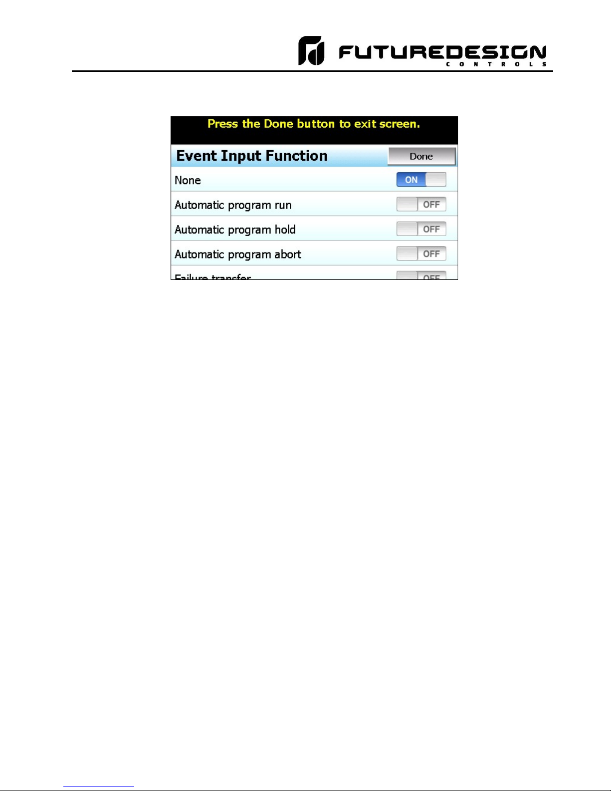
4.3.7 Event Input Function
The Event Input Function is used to select the desired mode of operation for the digital input of the loop control
board. The event input selections are mutually exclusive, i.e., selecting one will turn off the others. Once the
FDC MCT-MC - 24 - Configuring the MCT-MC
Page 25
MCT-MC 4.3
desired function has been selected, press the “Done” button to set the event input function for the loop control
board and return to the main Loop Configuration screen.
The Automatic program run function is a single-shot action that will start the currently loaded program when
the event input is activated.
The Automatic program hold function will put the currently running program into hold when the event input is
activated. The program will resume operation and return to the run mode when the input is deactivated.
The Automatic program abort function is a single-shot action that will abort the currently running program.
Note that the abort function does not work if the program is in hold. The program must be running in order for
the abort function to work.
The Failure transfer function puts the loop control outputs into failure transfer mode when the input is activated.
The output will then go to the percent output value set for failure transfer. The loop control outputs will return
to normal PID control when the input is deactivated.
NOTE: If an automatic ramp/soak program is in operation and one or both programmed control loops are
placed in failure transfer via the event input, the program will be stopped. When the event input is
then turned off and failure transfer is disabled, the loops will operate in static mode at the set point
and event output status prior to the time which the program was started.
The Automatic program advance next step function is a single-shot action that will advance the currently
running program by one step each time the event input is activated.
The Automatic program run/hold function is a combination of the automatic program run and program hold
functions. Upon first activation of the input, the currently loaded program will be started if not already running.
Deactivating the input will then cause the program to go into hold. The input must then be reactivated in order
for the program to resume operation.
The Loop status input function provides a visual indication on the Loop View screen in the runtime application.
When the input is activated, the border around the loop is highlighted blue. When the input is deactivated, the
border around the loop returns to the default dark gray color. This can be used as a means for alerting the user
of an operating condition, such as the equipment the loop is controlling is in operation.
The Alarm input function allows the event input to be used for alarm indication. When the input is activated,
the Event Input Alarm Message (see section 4.2.8) is displayed on the alarm screen in the runtime application
and the audible alarm sounds.
NOTE: The MC does not support the P41/B42 event input functions of “Manual Mode”, “Off Mode” and “PID2
Select”. These selections are not available through the MC configuration.
Configuring the MCT-MC - 25 - FDC MCT-MC
Page 26
MCT-MC 4.3
4.3.8 Event Input Alarm Message
When the event input function is set to alarm input, the Event Input Alarm Message entry allows the user or
OEM to assign the alarm message that will be shown on the alarm screen in the runtime application when the
input is activated. The alarm message can be up to 25 characters long.
4.3.9 Low/High Limit Setpoint
The low and high limit set points are used to set the minimum and maximum allowed set points that can be
entered for the loop control. These are typically set by the OEM to limit the control range to within the safe
operating range of the equipment.
NOTE: The runtime application provides additional user low and high set point limits. These can be adjusted
to further limit the allowable set point range within the band set by the OEM low and high set point
limits.
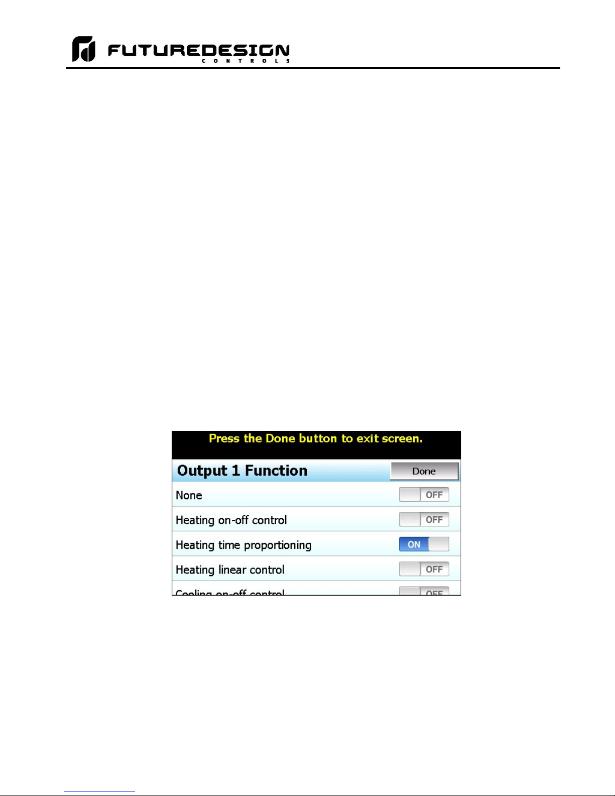
4.3.10 Output 1 Function
The Output 1 Function is used to set the mode of operation for the primary control output of the loop control
board. The output can be set for heating or cooling on/off control, time proportioning or linear control. The
output selections are mutually exclusive, i.e., selecting one will turn off the others. Once the desired function
has been selected, press the “Done” button to set the output function for the loop control board and return to
the main Loop Configuration screen.
NOTE: The output function must be set to match the type of output ordered on the loop control board. Relay,
triac and SSR output types are used for on/off and time proportioning control. The isolated Vdc and
mA output types are used for linear control.
The Heating on-off control function will turn on the output when the process value is below set point. When
the process value rises above the set point plus the on-off control hysteresis, the output will turn off.
The Heating time proportioning function uses the PID settings to cycle the output on and off according to the
percentage of heating required using the cycle time configured for output 1. For example, if the percentage of
output is 50% and the cycle time is 18 seconds, the output will repeat on/off cycles of 9 seconds each. If the
output was only 25%, the output would be on for 4.5 seconds and off for 13.5 seconds of the 18 second cycle
time.
The Heating linear control function uses the PID settings to vary the Vdc or mA output from the minimum to
the maximum range of the output as a direct percentage of the heating output.
FDC MCT-MC - 26 - Configuring the MCT-MC
Page 27

MCT-MC 4.3
The Cooling on-off control function will turn on the output when the process value is above set point. When
the process value falls below the set point minus the on-off control hysteresis, the output will turn off.
The Cooling time proportioning function uses the PID settings to cycle the output on and off according to the
percentage of cooling required using the cycle time configured for output 1. For example, if the percentage of
output is 50% and the cycle time is 6 seconds, the output will repeat on/off cycles of 3 seconds each. If the
output was only 25%, the output would be on for 0.75 seconds and off for 5.25 seconds of the 6 second cycle
time.
The Cooling linear control function uses the PID settings to vary the Vdc or mA output from the minimum to
the maximum range of the output as a direct percentage of the cooling output.
4.3.11 Output 1 Failure Transfer
The output 1 failure transfer setting is used to set the value the output should go to if there is an input failure,
i.e., sensor break. The output can be set for bumpless (-1) operation or a fixed percentage of output (from 0 to
100%) if proportioning or linear control is selected fro the output function. When failure transfer is set to
bumpless, the output will remain at its previous percentage of output until the input condition is corrected. Note
that this should not be used for extended periods of time as a runaway condition could occur if separate limit
devices are not installed to insure safe limits of operation by turning off the system should a limit be exceeded.
If the output function is set for on-off control, the failure transfer can be set to have the output turn on (1) or turn
off (0) when a sensor break occurs.
4.3.12 Output 1 ON-OFF Control Hysteresis
The output 1 on-off control hysteresis can be set when the output 1 function is set for heating or cooling on-off
control. It is used to eliminate rapid cycling of the control output by applying a safe-sided dead band to the
control output. When the control set point is exceeded, the output will turn on. The output will not turn off until
the process rises above (for heating) or falls below (for cooling) the set point by the hysteresis value.
The hysteresis can be set from a minimum of 0.1 to a maximum of 50.0 for units of degrees Centigrade and to
a maximum of 90.0 for units of degrees Fahrenheit and when a linear input type is used.
4.3.13 Output 1 Cycle Time
The output 1 cycle time can be set when the output 1 function is set for heating or cooling proportioning control.
The cycle time can be adjusted from 0.1 to 90.0 seconds. For cycle times less than 18 seconds, it is
recommended that the loop control board be ordered with the triac or SSR drive output for output 1 to extend
the life of the control output.
4.3.14 Output 1 Low/High Limit Values
The output low and high limit values can be set when the output 1 function is set for heating or cooling time
proportioning or linear control. They are used to set the minimum and maximum percentage of output that the
output will control to with a default of 0% for the low and 100% for the high. By raising the low limit or reducing
the high limit, the output will not exceed the output value regardless of the percent output required by the PID
values.
For example, raising the low limit to 5% with the output set for heating proportioning control, even if the process
value is over set point and the PID values are calling for a 0% output, the output will continue to cycle on and
off at 5% heating output.
Configuring the MCT-MC - 27 - FDC MCT-MC
Page 28
MCT-MC 4.3
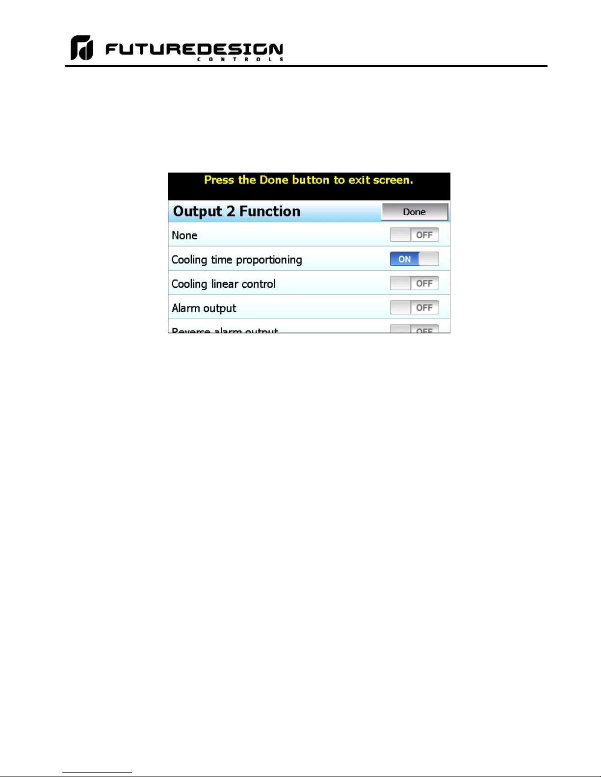
4.3.15 Output 2 Function
The Output 2 Function is used to set the mode of operation for the secondary control output of the loop control
board.
NOTE: The output function must be set to match the type of output ordered on the loop control board. Relay,
triac and SSR output types are used for proportioning control, alarm or event outputs. The isolated
Vdc and mA output types are used for linear control.
The output can be set for cooling time proportioning or linear control, an alarm or an event. The output
selections are mutually exclusive, i.e., selecting one will turn off the others. Once the desired function has been
selected, press the “Done” button to set the output function for the loop control board and return to the main
Loop Configuration screen.
The Cooling time proportioning function uses the PID settings to cycle the output on and off according to the
percentage of cooling required using the cycle time configured for output 1. For example, if the percentage of
output is 50% and the cycle time is 6 seconds, the output will repeat on/off cycles of 3 seconds each. If the
output was only 25%, the output would be on for 0.75 seconds and off for 5.25 seconds of the 6 second cycle
time.
The Cooling linear control function uses the PID settings to vary the Vdc or mA output from the minimum to
the maximum range of the output as a direct percentage of the cooling output.
The Alarm output function activates the Alarm 1 configuration settings for assigning the type of alarm logic to
apply to output 2. When the alarm condition is active, the output will turn on.
The Reverse alarm output function activates the Alarm 1 configuration settings for assigning the type of alarm
logic to apply to output 2. The output will be normally “on” when this function is selected. When the alarm
condition is active, the output will turn off.
The Event output function allows the output to be turned on and off via an automatic program or manually
through the MC runtime application to act as a “soft” switch to turn system components on and off.
The DC power supply output function must be selected when the output type ordered for the loop control
board output 2 is a transmitter power supply.
FDC MCT-MC - 28 - Configuring the MCT-MC
Page 29
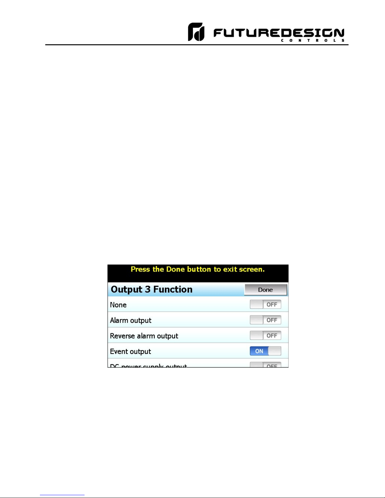
MCT-MC 4.3
4.3.16 Output 2 Failure Transfer
The output 2 failure transfer setting is used to set the value the output should go to if there is an input failure,
i.e., sensor break. The output can be set for bumpless (-1) operation or a fixed percentage of output (from 0 to
100%) if proportioning or linear control is selected for the output function. When failure transfer is set to
bumpless, the output will remain at its previous percentage of output until the input condition is corrected. Note
that this should not be used for extended periods of time as a runaway condition could occur if separate limit
devices are not installed to insure safe limits of operation by turning off the system should a limit be exceeded.
If the output function is set as an alarm, the failure transfer can be set to have the output turn on (1) or turn off
(0) when a sensor break occurs.
4.3.17 Output 2 Low/High Limit Values
The output low and high limit values can be set when the output 2 function is set for cooling time proportioning
or linear control. They are used to set the minimum and maximum percentage of output that the output will
control to with a default of 0% for the low and 100% for the high. By raising the low limit or reducing the high
limit, the output will not exceed the output value regardless of the percent output required by the PID values.
For example, by reducing the high limit to 80%, even if the process value is over set point and the PID values
are calling for 100% cooling, the output will only produce an 80% cooling output.
4.3.18 Output 3 Function
The Output 3 Function selection is used to configure the loop control board output as an alarm or an event.
The output selections are mutually exclusive, i.e., selecting one will turn off the others. Once the desired
function has been selected, press the “Done” button to set the output function and return to the main Loop
Configuration screen.
The Alarm output function activates the Alarm 2 configuration settings for assigning the type of alarm logic to
apply to output 3. When the alarm condition is active, the output will turn on.
The Reverse alarm output function activates the Alarm 2 configuration settings for assigning the type of alarm
logic to apply to output 3. The output will be normally “on” when this function is selected. When the alarm
condition is active, the output will turn off.
The Event output function allows the output to be turned on and off via an automatic program or manually
through the MC runtime application to act as a “soft” switch to turn system components on and off.
The DC power supply output function must be selected when the output type ordered for the loop control
board output 3 is a transmitter power supply.
Configuring the MCT-MC - 29 - FDC MCT-MC
Page 30
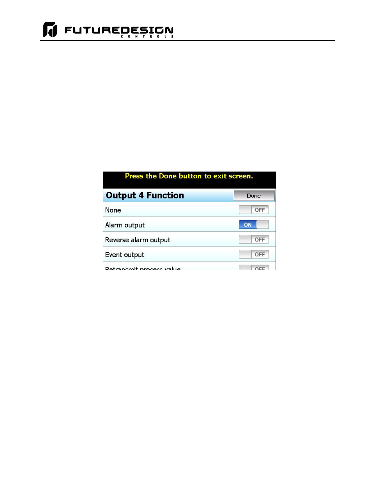
MCT-MC 4.3
4.3.19 Output 3 Failure Transfer
The output 3 failure transfer setting is used to set whether the output should be on (1) or off (0) when there is
an input failure, i.e., sensor break. The setting applies to alarm output functions only.
4.3.20 Output 4 Function
The Output 4 Function selection is used to configure the loop control board output as an alarm, event or
retransmit output. The output selections are mutually exclusive, i.e., selecting one will turn off the others. Once
the desired function has been selected, press the “Done” button to set the output function and return to the
main Loop Configuration screen.
NOTE: The output function must be set to match the type of output ordered on the loop control board. Relay,
triac and SSR output types are used for alarm or event outputs. The retransmission Vdc and mA
output types are used for process value or set point retransmit.
The Alarm output function activates the Alarm 3 configuration settings for assigning the type of alarm logic to
apply to output 4. When the alarm condition is active, the output will turn on.
The Reverse alarm output function activates the Alarm 3 configuration settings for assigning the type of alarm
logic to apply to output 4. The output will be normally “on” when this function is selected. When the alarm
condition is active, the output will turn off.
The Event output function allows the output to be turned on and off via an automatic program or manually
through the MC runtime application to act as a “soft” switch to turn system components on and off.
The Retransmit process value and Retransmit setpoint value functions allow the loop control board output
to retransmit the current input value or control set point to remote devices such as a chart recorder.
The DC power supply output function must be selected when the output type ordered for the loop control
board output 4 is a transmitter power supply.
4.3.21 Output 4 Failure Transfer
The output 4 failure transfer setting is used to set whether the output should be on (1) or off (0) when there is
an input failure, i.e., sensor break. The setting applies to alarm output functions only.
FDC MCT-MC - 30 - Configuring the MCT-MC
Page 31

MCT-MC 4.3
4.3.22 Output 4 Low/High Limit Values
The output low and high limit values can be set when the output 4 function is set for retransmit process or
setpoint value. They are used to set the minimum and maximum percentage of the output range for the installed
output type.
For example, the standard range of the mA output is 0-20mA. In order to use the output as a 4-20mA output,
the low limit value would need to be set to 20% (20% of 20ma = 4ma). For the voltage output, the default range
is 0-10Vdc. In order to achieve a 1-5Vdc output, the low limit would have to be set to 10% (10% of 10Vdc is
1Vdc). The high limit would then have to be set to 50% in order cut the output span in half to get a maximum
output of 5Vdc.
4.3.23 Output 4 Retransmit Low/High Scale
The output retransmit low and high scale can be set when the output 4 function is set for retransmit process or
setpoint value. They are used to set the retransmit range of the output. The low scale value corresponds to
the output low limit value and the high scale value corresponds with the output high limit value.
4.3.24 Alarm (1-3) Function
The Alarm 1, 2 and 3 Functions are used to select the alarm type for outputs 2, 3 and 4 respectively if the output
function is configured as alarm or reverse alarm. The alarm selections are mutually exclusive, i.e., selecting
one will turn off the others. Once the desired alarm type has been selected, press the “Done” button to set the
alarm function for the loop control board output and return to the main Loop Configuration screen.
NOTE: For the following alarm descriptions, PV = process value, SV = the control set point value, ASP is the
alarm set point and AHY is the alarm hysteresis.
A Process high alarm is independent of set point. When the process value is higher than the alarm set point
(PV > ASP), a process high alarm occurs. When the process value is lower than the alarm set point minus the
alarm hysteresis (PV < ASP–AHY), the alarm is off.
A Process low alarm is independent of set point. When the process value is lower than the alarm set point
(PV < ASP), a process low alarm occurs. When the process value is above the alarm set point plus the alarm
hysteresis (PV > ASP+AHY), the alarm is off.
Configuring the MCT-MC - 31 - FDC MCT-MC
Page 32

MCT-MC 4.3
A Deviation high alarm is dependant upon the control set point and alerts the operator when the process value
deviates too high over the set point value. For deviation high alarms, the alarm set point is entered as a positive
value. When the process is higher than the control set point plus the alarm set point (PV > SV+ASP), a deviation
high alarm occurs. When the process value falls below the control set point plus alarm set point minus the
alarm hysteresis (PV < SV+ASP-AHY), the alarm is off.
A Deviation low alarm is dependant upon the control set point and alerts the operator when the process
deviates too far below the set point value. For deviation low alarms, the alarm set point is entered as a negative
value. When the process is lower than the control set point plus the alarm set point (PV < SV+ASP), a deviation
low alarm occurs. When the process value rises above the control set point plus alarm set point plus the alarm
hysteresis (PV < SV+ASP+AHY), the alarm is off.
A Deviation band high/low alarm sets two trigger levels relative to the control set point value. For deviation
band alarms, the alarm set point is entered as a positive value. The two alarm trigger levels are then defined
as SV+ASP and SV-ASP for the high and low alarm values. When the process value is greater than the high
alarm value (PV > SV+ASP) or less than the low alarm value (PV < SV-ASP), a deviation band alarm occurs.
When the process value is within the high and low trigger levels by the value of the alarm hysteresis (PV <
SV+ASP-AHY and PV > SV-ASP+AHY), the deviation band alarm is off.
The End of automated program alarm is not associated with the process value or set point. The alarm is
turned on upon completion of an automatic ramp/soak program. The alarm will turn off when another program
is started, when power is cycled to the loop control board or when the “Reset” button is pressed on the Alarm
screen of the runtime application.
The Hold mode alarm is not associated with the process value or set point. The alarm is turned on when the
running program is in hold. The alarm will turn off when the program is placed back into run or the program is
stopped. Note that this “alarm” is not indicated on the MC interface.
The Static mode alarm is not associated with the process value or set point. The alarm is turned on when the
loop control is in the single set point (static) mode of operation. The alarm will turn off when the loop control is
running a ramp/soak program. Note that this “alarm” is not indicated on the MC interface.
4.3.25 Alarm (1-3) Mode
The Alarm 1, 2 and 3 Modes are used to select the mode of operation for outputs 2, 3 and 4 respectively if the
output function is configured as an alarm or reverse alarm. The mode selections are mutually exclusive, i.e.,
selecting one will turn off the others. Once the desired alarm mode has been selected, press the “Done” button
to set the alarm operation for the loop control board output and return to the main Loop Configuration screen.
Normal alarm action has the alarm output off in the non-alarm condition and on in the alarm condition. The
output state is inverted for a reverse alarm output.
FDC MCT-MC - 32 - Configuring the MCT-MC
Page 33

MCT-MC 4.3
Latching alarm action will keep the alarm output on even if the alarm condition has cleared until the alarm is
reset by the user. The output state is inverted for a reverse alarm output.
Hold alarm action prevents the alarm from activating on power up even when an alarm condition is present.
The alarm will be blocked until the alarm condition clears. Once cleared, the alarm will then operate normally
and activate when an alarm condition occurs.
The Latching and hold alarm action combines both the latching and hold alarm actions listed above.
4.3.26 Alarm (1-3) Indication
The Alarm 1, 2 and 3 Indication settings are used to select whether the alarm will be shown in the MC runtime
application or be hidden from the user. This allows the OEM to configure an alarm to perform a specific control
function while preventing the user from adjusting the set point or seeing the activation state of the alarm.
When the alarm indication is set for Hide alarm status/settings, the alarm will be removed from the MC runtime
application. The user will not be able to edit the alarm message or adjust the alarm set point. When the alarm
activates, there will be no indication or message on the alarm screen and the audible alarm will not sound. The
alarm operates as a “silent” alarm with no indication to the user.
When the alarm indication is set for Show alarm status/settings, the user will be able to access and change
the alarm set point and alarm message under the device settings. When the alarm occurs, the alarm message
will be displayed on the Alarm screen and the audible alarm will sound.
The indication selections are mutually exclusive, i.e., selecting one will turn off the other. Once the desired
alarm indication has been selected, press the “Done” button to set the alarm operation and return to the main
Loop Configuration screen.
NOTE: If the alarm is hidden but its mode is set for latching, the user will not have any indication that the
alarm requires manual reset. When an alarm is hidden, it is recommended that the normal or hold
mode be used so that the alarm output automatically resets when the alarm condition is no longer
present.
4.3.27 Alarm (1-3) Setpoint
The alarm set points can be set when the alarm function is set for a process or deviation type of alarm. If the
alarm indication is set to “show” the alarm status and settings, the set point will also be available in the MC
runtime application. If the alarm indication is set for “hide” alarm status and settings, the alarm set point will not
be available in the MC runtime application and can only be changed in the Configurator.
Configuring the MCT-MC - 33 - FDC MCT-MC
Page 34

MCT-MC 4.3
4.3.28 Alarm (1-3) Hysteresis
The alarm hysteresis can be set when the alarm function is set for a process or deviation type of alarm. It is
used to eliminate rapid on/off cycling of the alarm output by applying a safe-sided dead band to the alarm.
When the alarm set point is exceeded, the alarm will activate. The alarm will not deactivate until the process
rises above (for low alarm) or falls below (for high alarm) the alarm set point by the hysteresis value.
The hysteresis can be set from a minimum of 0.1 to a maximum of 50.0 for units of degrees Centigrade and to
a maximum of 90.0 for units of degrees Fahrenheit and linear input types.
4.3.29 Setpoint at Start of Automatic Program
The Setpoint at Start of Automatic Program entry is used to select the set point that will be used by the loop
control at the start of a ramp/soak program. The start set point selections are mutually exclusive, i.e., selecting
one will turn off the other. Once the desired starting set point has been selected, press the “Done” button to
return to the main Loop Configuration screen.
NOTE: If the MC control type is set for Dual Loop, Dual Loop + Cascade or Triple loop operation, it is
recommended that both loop 1 and loop 2 be set to the same selection so that both loop controls
start an automatic ramp/soak program in the same manner to avoid operator confusion.
The P41 and B42 loop control board provide a selection for using the start set point value of a
program. This selection is not supported by the MC and cannot be configured or entered for an
automatic program in the MC runtime application. Only the current PV or control SP selections are
supported.
The Current process value selection will cause the loop control to immediately assume the current process
value as the set point when the program is started. If the program is started on a ramp step, the program will
begin ramping the set point from the current process value to the target set point of the step. If the program is
started on a soak step, the program will hold the set point at the process value for the duration of the soak step.
The Current control setpoint selection will cause the loop control to use the current static set point when the
program is started. If the program is started on a ramp step, the program will begin ramping from the static set
point to the target set point of the step. If the program is started on a soak step, the program will hold the static
set point for the duration of the soak step.
FDC MCT-MC - 34 - Configuring the MCT-MC
Page 35

MCT-MC 4.3
4.3.30 Setpoint at End of Automatic Program
The Setpoint at End of Automatic Program entry is used to select the set point that will be used by the loop
control at the end of a program. The end set point selections are mutually exclusive, i.e., selecting one will turn
off the other. Once the desired end set point has been selected, press the “Done” button to return to the main
Loop Configuration screen.
IMPORTANT: If the MC control type is set for Dual Loop, Dual Loop + Cascade or Triple loop operation, both
loop 1 and loop 2 must be set to the same selection so that both loop controls end the program
in the same manner or a program run error will occur. When the final set point is used, the
program remains in operation on the end step with the final set point value while the program
ends and the unit returns to static set point operation. If one loop ends while the other remains
running in the end step, the automatic program run error will occur.
The Final setpoint of automatic program selection will use the final set point value programmed on the end
step of the program as the control set point when the program reaches the end step. All events will be turned
off and the program will remain in this condition until stopped by the user. Once the program is stopped by the
user, the control set point and manual events will return to the previous static set point and event activation that
were used prior to the program being started.
The Current control setpoint selection will return the control set point and event status to the previous static
set point and event selections that were used prior to program operation once the program reaches the end
step.
NOTE: The MC does not support the P41/B42 “all outputs off” end of program function”. This selection is not
available through the MC configuration.
4.3.31 Power Fail Recovery
The Power Fail Recovery entry is used to select the desired mode of operation of the loop control when power
is restored if an automatic ramp/soak program was running at the time power was lost. The recovery selections
are mutually exclusive, i.e., selecting one will turn off the others. Once the desired recovery mode has been
selected, press the “Done” button to set the power recovery mode for the loop control board and return to the
main Loop Configuration screen.
For additional information regarding the manner in which program recovery is achieved, see the Appendix
section A.3 Power Recovery Detail.
Configuring the MCT-MC - 35 - FDC MCT-MC
Page 36
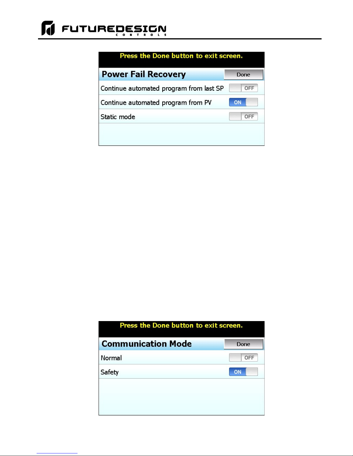
MCT-MC 4.3
The Continue automated program from last SP selection will resume the program from where it left off with
the last set point set by the program at the time of power failure.
The Continue automated program from PV selection will resume the program using the current process value
at the time power is restored as the set point.
The Static mode selection will terminate the automated program and return the loop control to the single set
point mode of operation using the previous set point value prior to starting the automatic program. In addition,
any outputs configured as events will also be returned to their previous on/off prior to starting the program.
NOTE: The MC does not support the P41/B42 “Off Mode” recovery option. This selection is not available
through the MC configuration.
4.3.32 Communication Mode
The Communication Mode selection is used to specify how the loop control responds to a loss of
communications with the MC display. The communication mode selections are mutually exclusive, i.e.,
selecting one will turn off the other. Once the desired mode has been selected, press the “Done” button to set
the communication mode for the loop control board and return to the main Loop Configuration screen.
NOTE: It is recommended that the “Safety” communication mode be used to insure all outputs are turned off
(linear outputs set to 0%) in the event of a loss of communications between the MC and the loop
control.
FDC MCT-MC - 36 - Configuring the MCT-MC
Page 37

MCT-MC 4.3
With the Normal mode selection, the loop control will continue operation according to the last command given.
When power is first applied to the loop control, its outputs will activate immediately according to the last
commands given prior to power loss.
With the Safety mode selection, all loop control outputs will be turned off in the event of a loss in
communications with the MC display that exceeds 60 seconds. Since the MC display provides the means for
control and monitor of loop operation, this insures that any devices connected to the loop control outputs can
be shut down/turned off until corrections can be made to restore communications.
It also insures that when power is first applied, the loop control outputs will not activate until proper
communication is established with the MC display. This prevents any devices connected to the loop control
outputs from being activated until the runtime application has started to provide the user with access to the
system.
4.3.33 Monitor Only Mode
The Monitor Only Mode selection can be used to turn a control loop into a “monitor only” device, i.e., hide the
loop set point and percentage of output in the MC runtime and only display the input value. This provides an
easy method for adding another input to the system for monitoring the value of a process, while also providing
additional outputs that could be used as events, sensor power supply, etc.
Configuring the MCT-MC - 37 - FDC MCT-MC
Page 38
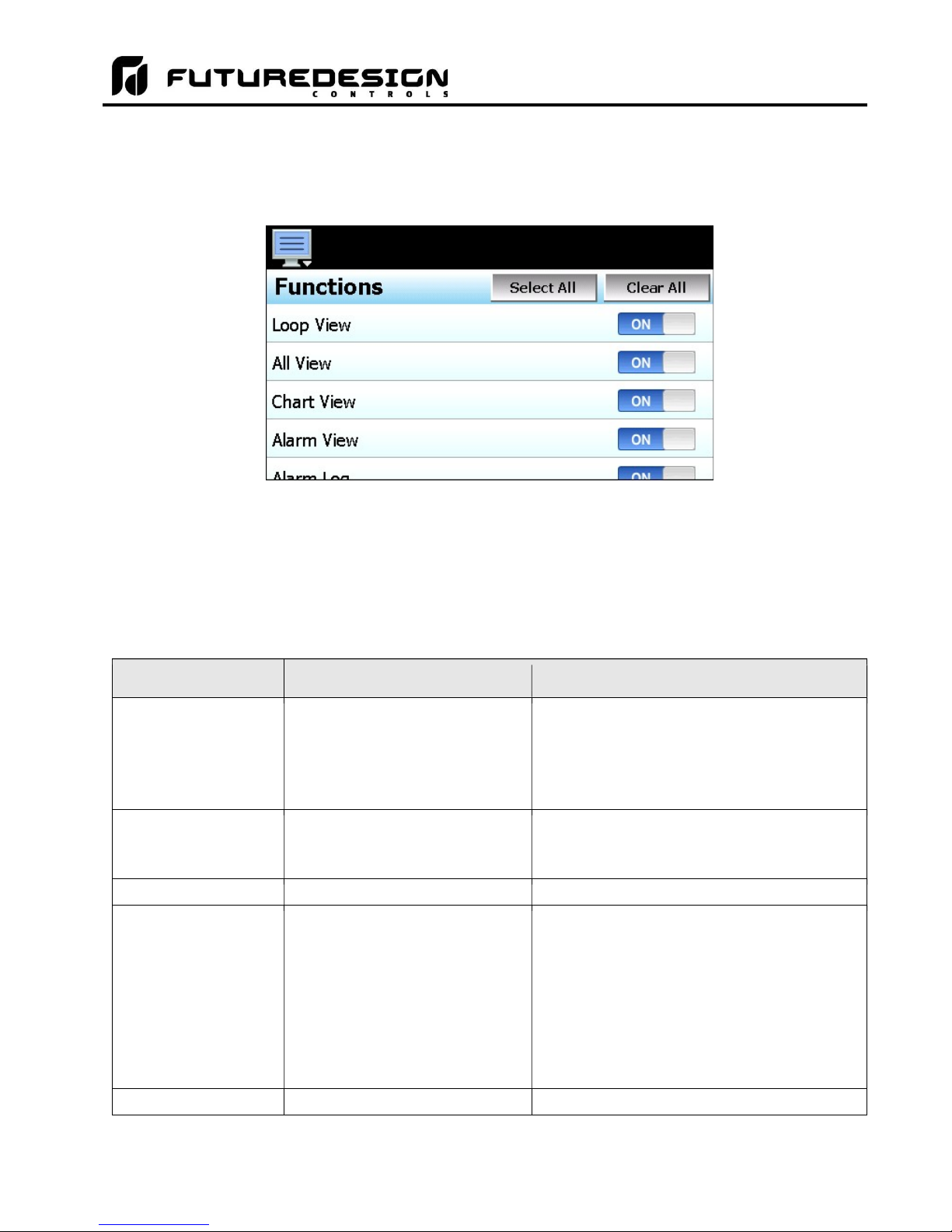
MCT-MC 4.3
unable to turn manual event outputs on and off.
user will be unable to
monitor or adjust loop operation
. Chart View
View\Chart view and set up real time trends for loops and monitors
flashing alarm icon.
Alarm Log
View\Alarm
File vie
w and email alarm history files
4.4 Functions
The MC functions are accessed from the Startup menu and allow the user or OEM to select which screens/menu
items will be enabled (shown) in the runtime application. These functions can be used to customize the system
to meet specific requirements.
When functions are disabled at the Configurator level from the functions list, it will be disabled in the runtime
software by removing the menu item or disabling the field so the operator can not select the function or edit any
corresponding settings related to the function. The following list provides the available MC functions, where to
find the menu item(s) applicable to the function and a description of what it applies to.
IMPORTANT: Disabling functions that are not required for the application results in a system that is clean and
easy to use for the operator; however, be careful when disabling certain items. Without access
to them, there may be no way to determine if the system is operating as required.
MC Function Runtime Menu Location Description
Loop View View\Loop View loop PV, %Out, set loop set point and set fixed
All View View\Overview view loop PV, %Out, set loop set point
Alarm View View\Alarm
Notifications
percentage of output
NOTE: Without access to the loop view screen, the user
will be unable to set a fixed percentage of output for the
loop. If access to All View is also removed, user will be
NOTE: If access to the Loop View is also removed, the
view and reset current alarms
current alarm status
NOTE: With the function disabled, the user will only be
able to access the alarm screen to reset an alarm when
the alarm occurs by pressing the flashing alarm icon.
If the alarm is latching and does not reset, the user will
be unable to return to the screen to try and clear the
alarm unless another alarm occurs to again display the
FDC MCT-MC - 38 - Configuring the MCT-MC
Page 39

MCT-MC 4.3
enable security menu to gain access to the
audit files.
be unable to access or start programs via the interface.
delete data, alarm, audit or
program files.
Data Log Viewer
Data\Chart access to view historical data log files
Annotations
Data\View\Annotation
access to add and view operator annotations to data files
Digital Signatures
Data\View\Signature
access to view and add digital
signature to data log file
FTP if unit is so configured.
configured.
percentage of output
loose the ability to place the loop in auto tune
.
MC Function Runtime Menu Location Description
Security Settings Security
Automatic Program
Control/Recovery
Data Logging Data\Data
Notifications
Program
Device\Settings\Offline\Set\Recovery
Notifications
Notifications
view/set security rights, view audit trails, user log on
view security and audit status
NOTE: If security is enabled, but system security is then
disabled through this item, the user will be unable to log
on. Default security (operator level) access will be used.
This allows audit trails to be active while hiding all user
security features.
With security menu disabled, audit trail files are
accessible via Log/USB File Utilities or temporarily re-
view, create, edit and run automatic ramp/soak programs
set power recovery mode
view program status
NOTE: When disabled, all program items and menus will
be removed from the runtime application. The user will
enable/disable data logging, select points for logging,
access to historical viewer, FTP and USB File utilities
view data log status, length and interval
NOTE: If data logging is set to log on program operation
or when the MC starts and this menu is then disabled,
data logging will be disabled. This menu item must
remain visible in order for the built in data logging of the
MC to function.
The USB File utilities will not be accessible to copy or
File Utilities Data\Utilities\USB access to copy/delete alarm, audit, program and data log
FTP/WAN Settings Data\Utilities\FTP/WAN access to view/configure FTP file transfer settings
Loop Manual Mode View\Loop access to placing the loop in manual and setting a fixed
Loop PID Tuning Device\Settings\View\Tuning access loop tuning screen
Configuring the MCT-MC - 39 - FDC MCT-MC
files
Note: Alarm, audit and data files may be transferred via
NOTE: Once the FTP is configured for Auto Backup in
the runtime application, this menu item can be disabled
and hidden from the operator so that OEM configuration
is preserved and can not be accessed or altered. The
Auto Backup to the FTP Server would occur as
NOTE: With loop PID tuning disabled, the user will also
Page 40

MCT-MC 4.3
background remov
ing all access by the operator.
Email/SMTP Settings
Device
\
Settings
\
Email\Email
access to view/configure email settings
Notifications
view web server and VNC status
names.
Temperature Units
Device
\
Settings
\
Offline
\
Set\Units a
ccess to set temperature units
Input Calibration
Device
\Settings
\
Offline
\
Calibrate
\
Inputs
access to input calibration for all loops installed
Configuration
configuration or restore configuration from back
-
up file
Setpoint Limits
Device
\
Settings
\
Set\Limit access loop set point high
and
low entry
limits
menus and online help
Exit Application
Device
\
Settings
\
Offline
\System
\
Exit access to the exit application screen
startup)” button
Operation
Operation
MC Function Runtime Menu Location Description
Alarm Settings Device\Settings\Set\Alarm access alarm settings
Communication Settings Device\Settings\Set\Comms
Edit Event Names Device\Settings\Set\Event access to view/edit system event names
Import/Export Setup Device\Settings\Offline\System\
Language
Exit to Configurator Device\Settings\Offline\System\Exit –
Device\Settings\Offline\Set\Language
“Exit Application. (configuration mode
NOTE: Alarms can be fully programmed in the
Configurator and hidden in the runtime by disabling this
function. The alarms will operate as programmed in the
access to web server, Modbus and VNC settings
NOTE: Event names can be assigned in the runtime and
then this item disabled to prevent changes to event
access import/export utility to back up current Orion-M
access to set the MC display language selection for
access to the exit the application and start the
Configurator on the next power cycle
Loop view Manual
Loop View Program
View\Loop – “Manual Operation” button access for turning manual events on and off
View\Loop – “Program Operation” button access to program selection and run/hold control
FDC MCT-MC - 40 - Configuring the MCT-MC
Page 41

MCT-MC 4.3
4.5 Startup View
The Startup View screen is accessed from the Startup menu and allows the user or OEM to define which of the
main view screens the runtime application will display when it first starts and when the “Home” icon is pressed.
The available selections are Loop View, All View, Chart View, Alarm View and Alarm Log.
NOTE: If the selected screen to view on startup is disabled in the MC functions list, the screen will only be
available when the “Home” icon is pressed.
4.6 Alarm Names
The Alarm Names screen is accessed from the Tagnames menu and allows the user or OEM to edit the name
(alarm message) of all configured alarms. In order to access the screen, there must be at least one loop control
output configured as an alarm.
The alarms will be listed in sequential order starting with any outputs programmed as an alarm on loop 1 through
loop 10. The default alarm names are ALM#1, 2, 3, etc. To assist in identifying which device/output the alarm
is assigned to, the list includes the alarm source. The alarm names will be displayed in the runtime application
as the alarm description on the Alarm screen. To change the name of an alarm, select the alarm from the list
and enter the desired text up to 25 characters.
Configuring the MCT-MC - 41 - FDC MCT-MC
Page 42

MCT-MC 4.3
4.7 Event Names
The Event Names screen accessed from the Tagnames menu and allows the user or OEM to edit the names
of all configured event outputs. In order to access the screen, there must be at least one loop control output
configured as an event.
The events will be listed in sequential order starting with any outputs programmed as an event on loop 1 through
loop 10. The default event names are EV1, 2, 3, etc. To assist in identifying which device/output the event is
assigned to, the list includes the event source. The event names will be displayed in the runtime application
on the Manual Operation slide out, All View and program Entry screens. To change the name of an event,
select the event from the list and enter the desired text up to 9 characters.
4.8 Custom Name\Address
The Custom Name\Address screen is accessed from the Tagnames menu and is typically used by the OEM to
configure the main splash screen when the MC runtime application starts. It allows the company name and
contact information to be entered and shown each time the MC is powered up. It also allows the name of the
controller to be changed in order to adapt it to a specific product or market.
To edit the company, address, phone number or controller (product) name, press the field and enter the desired
text. Each field can be entered with a maximum of 24 characters that will be displayed on the splash screen
when the MC starts.
FDC MCT-MC - 42 - Configuring the MCT-MC
Page 43

MCT-MC 4.3
5 Basic Operation
This section is designed to help guide the user through the MC touch screen interface and menu structure in
order to navigate through the various operation, monitor and setup screens and gain an understanding of how
to use them. Subsequent sections of this manual are tailored to the special features and functions of MC.
Consult those sections of the manual for further information and specifics on how to set up and operate them.
5.1 OEM Configuration Options
The availability of certain menu items, screens and the functionality of MC are determined by the configuration
of the loop control(s). This manual covers all available options, some of which may not be available on your
system.
If there are questions or concerns about the operation and available options on your MC controller, contact your
OEM for further information. Only your OEM can address equipment related issues.
5.1.1 Loop Control Monitor Only Mode
The loop control monitor only selection in the Configurator provides an OEM with a low cost video recorder
option to use in place of a standard circle/strip/paperless recorder. When the loop monitor only function is
enabled in the Configurator for a loop, the MC automatically configures itself to remove all set point fields,
automatic ramp/soak program control options, loop tuning and set point limit access so that only the loop
process value (PV) is available for the monitor only loop.
- Loop View on single loop system - - Loop View on 10 loop system -
Unlike your basic chart recorder; however, the loop controls are still functional. They can be used to control a
process if there is the need for fixed, single set point control. A loop can be programmed with a fixed set point
by the OEM, and it will then control the process in the background without the need for any user access.
The OEM can also provide events for the user to turn equipment on or off, and alarms can be configured to
alert the user to process changes.
If one control loop is required while another point is for recording only, enabling the monitor only mode on an
individual loop in the Configurator will remove the set point fields, program operation, tuning and set point limit
access for that specific loop only. The other loop(s) will maintain all control functions including the automatic
ramp/soak program operation, while the monitor loop will be shown as a monitor only point for recording
purposes.
Basic Operation - 43 - FDC MCT-MC
Page 44

MCT-MC 4.3
main menu for navigating to the different control and
monitoring screens. Menu items will dynamically appear providing available options
display text based help associated with the current
screen. Help is available in 10 languages based on the user selection in the offline setup
The home icon will return the user to the main view from anywhere in the MC application.
e main view is set by the OEM in the MC configuration and can be the loop, chart,
The alarm icon will appear and flash when a new system alarm occurs. Pressing the
larm monitor screen in order to view and /or
The left and right navigation arrows will appear on screens that provide additional
information that the user can scroll to such as the loop view screen, charts or program
5.2 Touch Screen Interface
The MC display is split into two sections; the icon bar and main display area.
Icon Bar
Main Display
Loop View Screen
The menu icon will open the
based on the system area the user is in, i.e., security, data logging, setup, etc.
The information (help) icon will
of section of MC.
Th
alarm, alarm history, or overview screen.
alarm icon will take the user directly to the a
reset the active alarm condition.
entry screen in order to cycle through each step of a ramp/soak program.
NOTE: A single press of the left or right arrows will scroll program steps to the next step or screens
to the next available screen option (i.e. chart number). Pressing and holding the arrow
keys will continue the item scrolling until the last step of the program is reached or the
button is released.
IMPORTANT: Do not use any sharp or metal objects on the touch screen as they may damage the
surface. Also be sure that hands and fingers are free from oils or chemicals which may
mar the surface of the touch screen.
FDC MCT-MC - 44 - Basic Operation
Page 45

MCT-MC 4.3
5.3 Menu Navigation
The MC provides the user with the ability to select text based menu navigation, much like the typical file menu
system of a PC, as well as an icon based navigation system like that of a “smart” device. The user can switch
back and forth between the two from the Setup menu.
Text Based Navigation
Touch and drag
finger across
screen to switch
between menu
pages.
Active Page
Indicator (1 of 3)
Icon Based/Slide Page Navigation
The available menu items are dependent upon the OEM configuration of MC. Not all of the menu items shown
may be available on your system. The following information is provided as an overview of the full navigational
menus for the MC.
Basic Operation - 45 - FDC MCT-MC
Page 46

MCT-MC 4.3
5.3.1 Home Menu
The home menu is the top level, default menu provided when MC first powers on. Pressing the menu (monitor)
icon will display the main menu offering the selections shown below.
5.3.1.1 Text Based Home Menu
The View menu provides navigation to all standard view screens. These include
the Loop view, real time Chart, Alarm monitor, Alarm File and Overview control
screens.
The Program menu provides access to the automatic ramp/soak program
actions, Entry and Status views.
The Device menu provides access to the MC controller settings. These include,
loop set point entry limits, alarm set points, communication settings, email setup
as well as access to offline settings for date/time, etc.
The Security menu provides access for user login, security settings and audit
trail viewing if the security system is enabled.
The Data menu provides access to data log functions, file utilities, FTP\WAN
back-up settings as well as the historical data viewer.
FDC MCT-MC - 46 - Basic Operation
Page 47

MCT-MC 4.3
5.3.1.2 Icon/Slide Page Based Home Menu
Slide page 1 provides navigation to all
standard view screens. These
include the Loop and Overview,
Chart, Alarm monitor, and Alarm File.
It also provides quick access to the
MC Settings and Data file functions
which include file utilities, FTP\WAN
back-up settings as well as the
historical data viewer.
Slide page 2 provides access to
program Entry and Status views.
Slide page 3 provides access to
Configure security settings, Audit trail
viewing, current User information,
user Password editing and user Login
and Log Off functions.
Basic Operation - 47 - FDC MCT-MC
Page 48
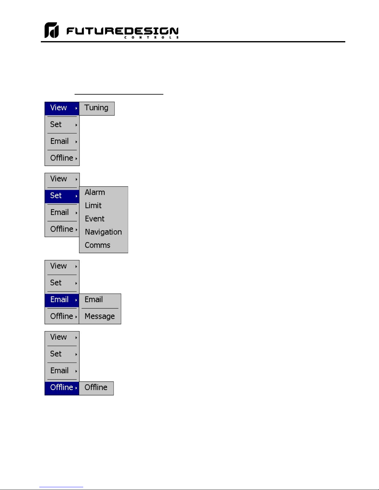
MCT-MC 4.3
5.3.2 Device Settings Menu
The device settings menu is provided when the user selects “Settings” from the main “Device” menu. See
section 9 on Device Settings for detailed information on these settings and their use.
5.3.2.1 Text Based System Setup Menu
The View menu provides navigation to the manual loop Tuning screen.
The Set menu provides access to setting Alarm set points, control loop set
point Limits, Event tagnames, Navigation type selection and
Communications options.
The Email menu provides settings for the email server to send SMS text
messages and/or emails on alarm and allows the user to compose and
send a Message to any user configured in the system.
The Offline menu provides access to the MC offline setup which provides
the user with the ability to adjust the date/time, calibrate the touch screen,
configure profile power recovery options, etc.
FDC MCT-MC - 48 - Basic Operation
Page 49
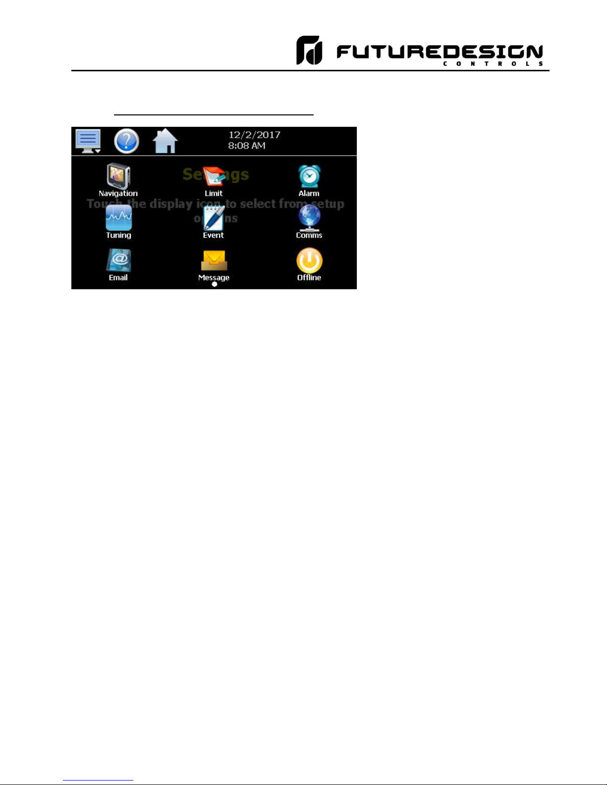
MCT-MC 4.3
5.3.2.2 Icon/Slide Page Based Device Settings Menu
The slide page provides access to
Navigation type, control loop set
point Limits, Alarm set points, loop
Tuning, Event tagname entry and
Email server settings and
Messaging.
It also includes access to the
communications settings for the
web page, VNC server and Modbus
user communications.
Basic Operation - 49 - FDC MCT-MC
Page 50

MCT-MC 4.3
5.3.3 Offline Menu
The offline menu is provided when the user selects “Offline” from the device settings “Offline” menu. See
section 10 on Offline Settings for information on these settings and their use.
NOTE: Offline settings can only be accessed when an automatic ramp/soak program is not running and data
logging is turned off.
5.3.3.1 Text Based Offline Setup Menu
The View menu provides navigation back to the MC device settings menu.
The Set menu provides access to the profile power Recovery options,
temperature Units selection, NTS Clock, and Language settings.
The Calibrate menu provides access to the user input calibration for the
control loop/limit inputs.
The System menu provides access to the MC Display settings,
import/export Configuration utility, About screen and Exit application
screen.
FDC MCT-MC - 50 - Basic Operation
Page 51
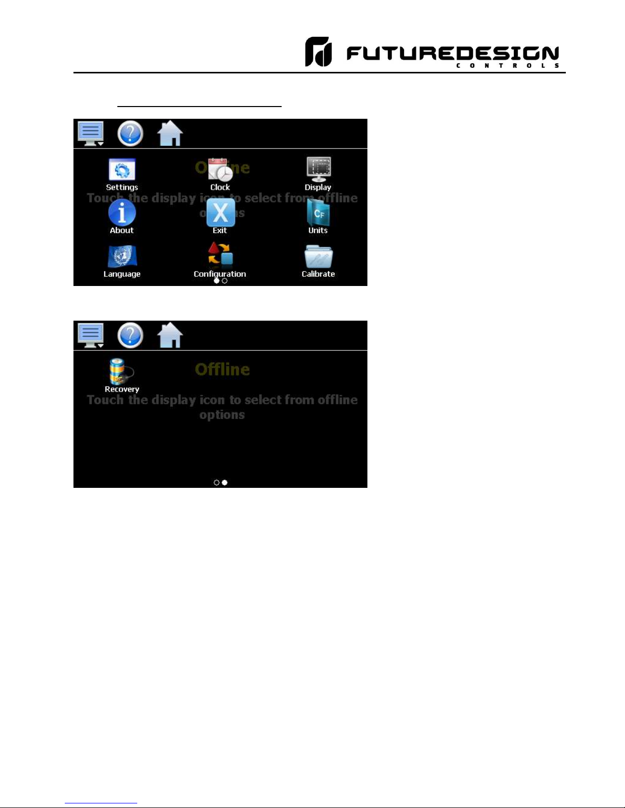
MCT-MC 4.3
5.3.3.2 Icon/Slide Page Based Offline Menu
Slide page 1 provides navigation
back to the device Settings menu,
Clock, Display settings, About MC
and Exit application screens,
temperature Units selection,
Language, import/export
Configuration utility and input Offset
calibration.
Slide page 2 provides access to the
automated program power
Recovery options.
Basic Operation - 51 - FDC MCT-MC
Page 52
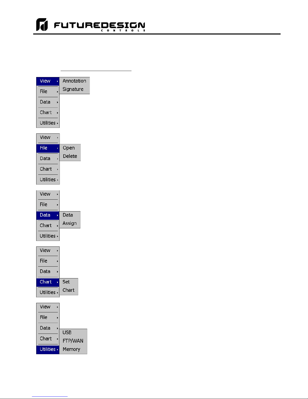
MCT-MC 4.3
5.3.4 Data Menu
The data log menu is provided when the user selects “Data” from the main “Data” menu. See section 8 on Data
Logging for information on these settings and their use.
5.3.4.1 Text Based Data Logging Menu
The View menu provides access to the data file Annotation and digital Signature
screens.
The File menu provides functions for opening and deleting historical data log files.
The Data menu provides access to the main Data screen for starting and stopping
data logging and to the log point Assignment screen where the user can select
which items are to be logged to the history file.
The Chart menu provides functions for viewing historical data files in graphical
format.
The Utilities menu provides access to the MC file management utilities including
USB file transfer and FTP/WAN back-up.
FDC MCT-MC - 52 - Basic Operation
Page 53
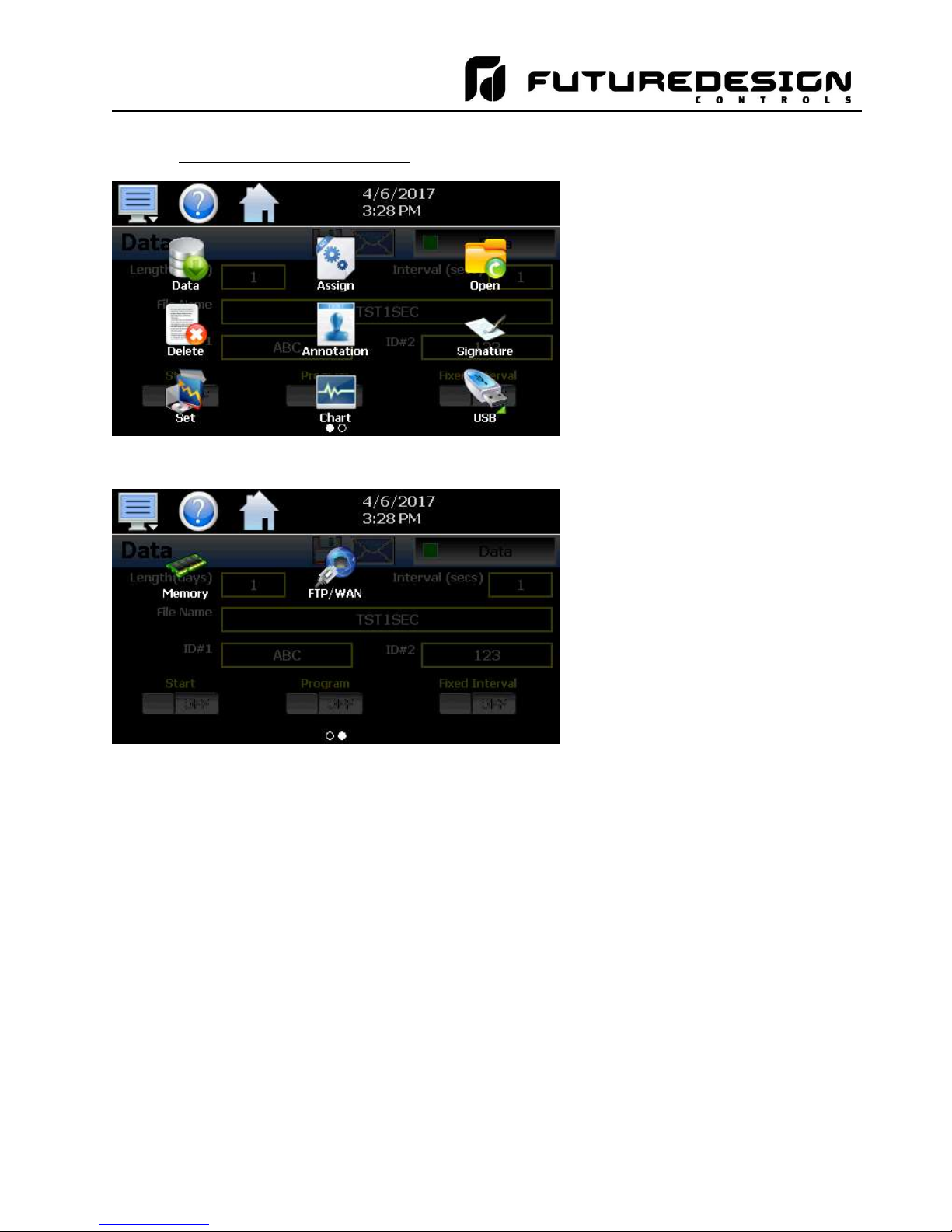
MCT-MC 4.3
5.3.4.2 Icon/Slide Page Based Log Menu
Slide page 1 provides access to the
main Data log screen and to the log
point Assignment screen where the
user can select which items are to
be logged.
Historical data file functions are
provided for Opening and Deleting
historical files and viewing/setting
data file Annotations and digital
Signatures.
The plot Set and Chart icons
provide access to the historical data
viewer options.
Slide page 2 provides access to the
FTP/WAN back-up settings and the
memory check utility for viewing
available system/storage memory
space.
Basic Operation - 53 - FDC MCT-MC
Page 54
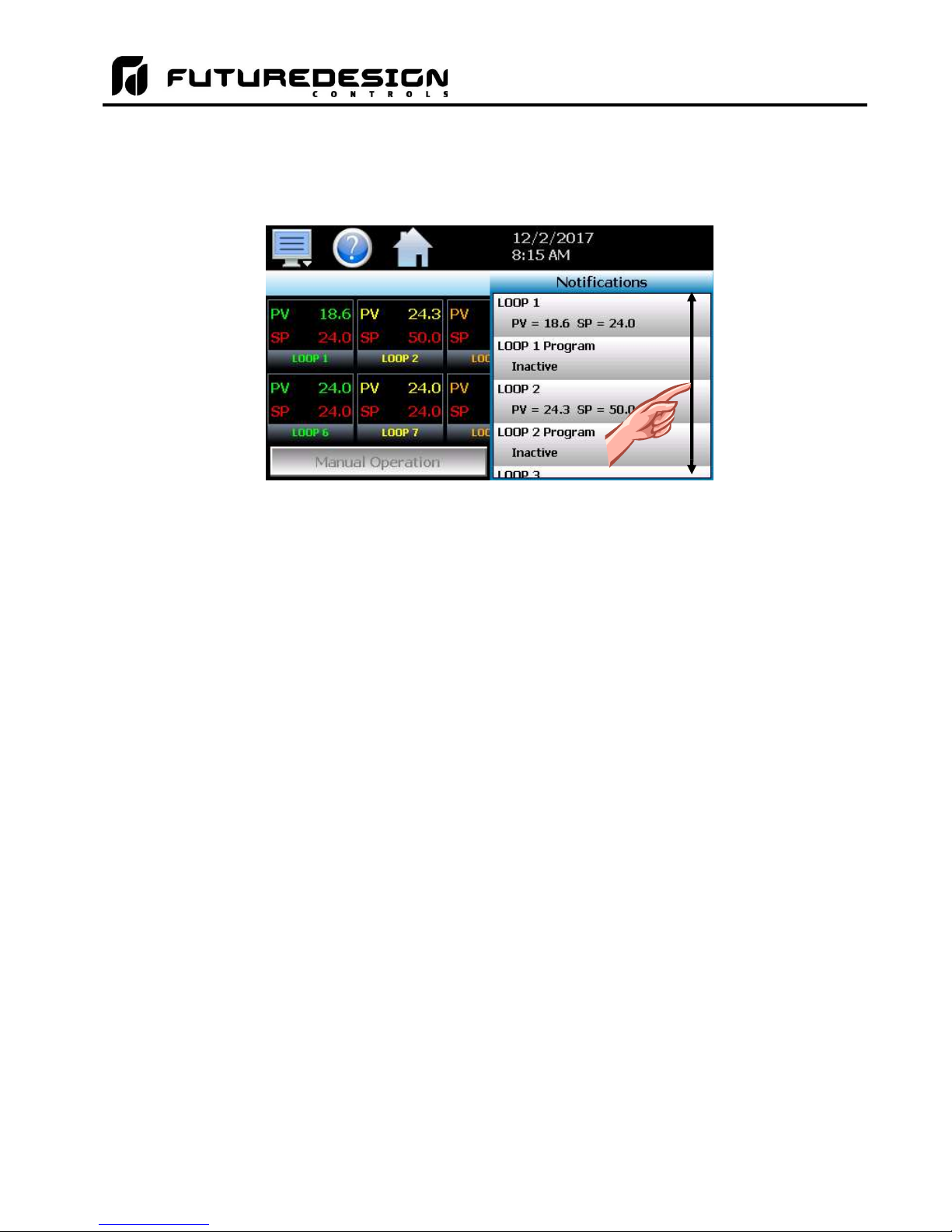
MCT-MC 4.3
5.4 Notifications
The notification window is a feature that can be accessed by pressing the date/time field in the icon bar. This
window provides a snapshot of current MC activity. The notification window can be closed by pressing the
date/time field again, or is automatically closed if the Menu, Home or a navigation arrow icon is pressed.
A user can view all notifications by touching the screen and dragging their finger up or down on the list to
scroll through all items like other lists in MC. The notifications include the following:
• Loop PV and SP for each loop configured.
• Automatic program status including name of running program for each loop configured.
• Active alarm status including the most recent alarm.
• Data logging status including active file name and the length and logging rate set.
• Security status including the current user.
• Audit trail active/inactive status.
• Web server active/inactive status.
• VNC server active/inactive status.
• MC IP address.
• Available SD storage memory remaining.
The appearance of the items is based on the configuration of the MC. If data logging or security functions are
disabled in the Configurator for example, their status items will be removed from the list as well.
NOTE: The notification items do not update while the list is shown. The information shown in the list is a
snapshot of the data at the time the window was shown. Therefore, the PV or SP shown for a loop
may not be the actual values for the loop if the notification window is left open for extended periods
of time. The notification window is not available in the offline setup.
FDC MCT-MC - 54 - Basic Operation
Page 55

MCT-MC 4.3
5.5 Control Loops (Single Set point Operation)
The Loop view screen provide direct viewing options for the control and monitoring of the MC control loops.
The Loop screen allows the user to adjust the current loop set point (SP) and view the process variables (PV)
and percentages of output (%) for each loop (when viewing up to 5 loops).
5.5.1 Loop View
The Loop screen is accessed from the home “View” menu. It can display from 1 to the maximum number of
loops configured in the system. The maximum loops that can be viewed on the screen is determined by the
“Loops to View” setting on the Navigation screen (see section 9.6).
Press PV value
for historical
min/max.
Press PV tag to
reset historical
min/max.
Press % tag to
enable/disable
manual output.
Percent Output
Entry Field
Set Point Entry
Field
Loop Units
Loop Name
The set point entry field is the area where the screen can be touched in order to bring up the keypad entry
window. Using the numeric entry keypad, a new set point can be entered. Once entered, the new set point will
be shown in the set point entry field. Adjustment of the set point is locked out if an automated ramp/soak
program is running.
IMPORTANT: When operating in single set point mode, the set point is saved in the loop control board’s
memory once every 6 minutes. If the set point is changed and power is removed prior to the 6
minute time period, when power is re-applied, the loop set point will return to the previous value.
Insure that power remains on the unit for 6 minutes after a set point change in order to have it
power-up with the desired set point the next time power is applied.
The percent output entry field is the area where the screen can be touched in order to bring up the keypad
entry window. Using the numeric keypad, a new fixed percentage of output can be set for the loop. In order to
be able to enter a fixed output percentage, the loop must first be placed in manual output mode. This is done
by pressing the “%” tag on the screen. This feature can be removed by turning off the “Loop Manual Mode”
function in the Configurator.
NOTE: If more than 5 loops are shown on the loop view screen, the percent output fields are removed from
view in order to display additional loop information. Manual mode operation for each loop can still
be accessed from the Tuning screen (see section 9.1).
The loop name and loop units, shown at the bottom of each loop (or limit), will display the tagname and units
as entered in the Configurator.
Basic Operation - 55 - FDC MCT-MC
Page 56

MCT-MC 4.3
5.5.1.1 Historical Minimum and Maximum
The MC monitors and stores the minimum and maximum process value reached during operation for each loop
in the system. The current historical values can be viewed by pressing the process value display field for the
desired loop.
Pressing the “OK” button will close the dialog window and return to the Loop view screen. The historical values
are reset each time the runtime application is started, and can also be manually reset by pressing the “PV” tag
on the Loop view screen.
Pressing the “Yes” button in the dialog window will reset historical minimum and maximum values and default
them both to the current process value. Pressing “No” will simply close the dialog.
FDC MCT-MC - 56 - Basic Operation
Page 57
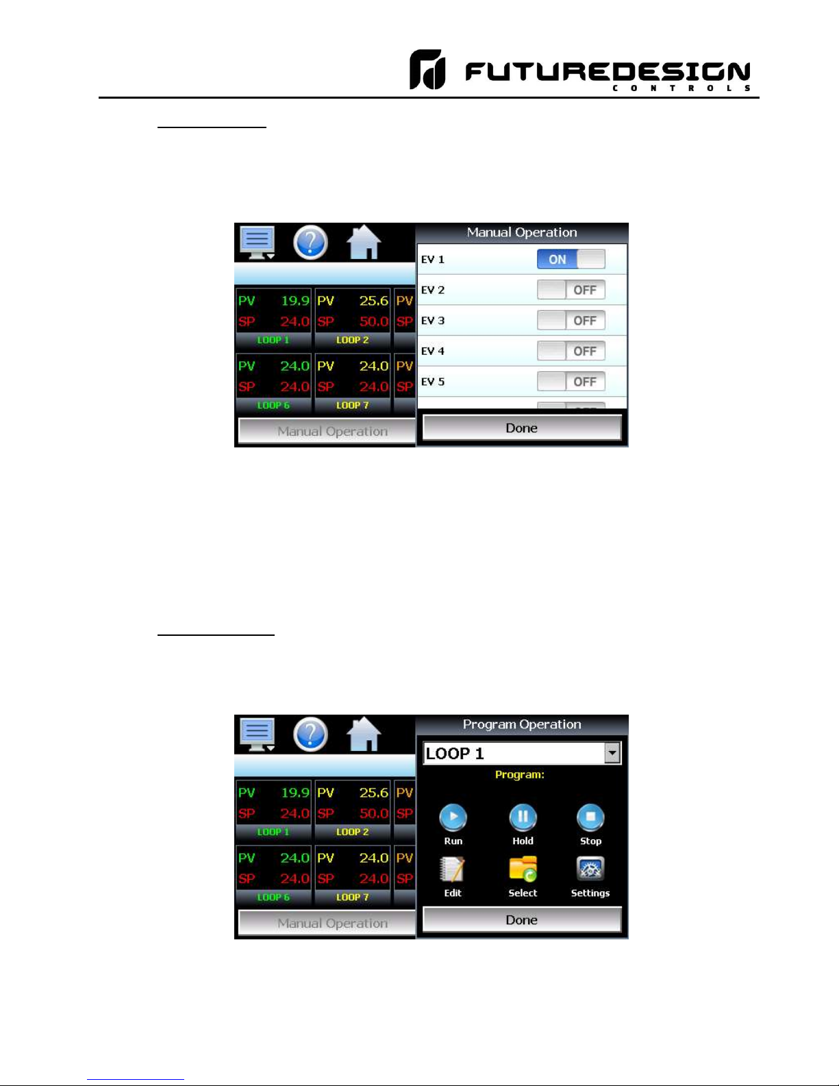
MCT-MC 4.3
5.5.1.2 Manual Operation
The Manual Operation button displays a “slide out” window providing access to all events programmed for the
system. To turn each event and its corresponding output on or off, simply press the button associated with the
event. Slide the list up or down as necessary to view additional events if more are programmed than can be
displayed in the window at one time.
NOTE: The MC loop controls can provide up to 3 event outputs each (for a total of 30 events). Depending
upon the configuration of MC, some outputs may perform specific control or alarm functions. The use
of each output, and what it controls, is determined by the system designer. If there are questions or
concerns about the configuration and operation of your MC controller, contact your OEM for further
information. Only your OEM can address equipment related issues.
The names of events are also determined by the system designer. The screen shot above is an
example. Consult section 9.3 on Event Names on how to change the names of events.
5.5.1.3 Program Operation
The Program Operation button displays a “slide out” window with all automated program operations included.
Press the desired icon for quick access to any program operation. The “Select” icon can be used to select any
program stored for quick run operations. The “Settings” icon provides access to the program mode selections.
Basic Operation - 57 - FDC MCT-MC
Page 58

MCT-MC 4.3
5.5.2 Overview Screen
The Overview provides a list of all loops configured in the system. It is accessed from the home “View” menu.
If the MC is configured as a single loop system only loop one will be shown. The screen allows manual set
point entry for each loop by touching the respective loop tag name or PV, SP and %Out display field. Touching
the “Program” field in the row for the loop will display the “slide out” Program Operation window.
The Manual Operation button displays the “slide out” window to access all events configured in the system.
The “scrolling” alarm field at the bottom of the Overview screen will cycle through any and all alarms that are
active in the system.
Current Program
Loaded/Status
NOTE: If the automatic ramp/soak program mode setting is set to “All”, the current program loaded field for
the primary loop will display the program information. All other “slave” loops will indicate that they
are under set point control of the primary loop by displaying the name of the primary loop in
parenthesis. See section 6, Automatic Ramp/Soak Program Operation for more information.
FDC MCT-MC - 58 - Basic Operation
Page 59

MCT-MC 4.3
5.6 Process Monitoring
The Loop and Overview screens provide the current process values of the MC. In order to view the process
inputs over time, the MC provides real-time charts. Four user configurable charts are provided with up to eight
plot points per chart.
5.6.1 Charts
The Chart screen is accessed from the home “View” menu. The real-time charts can be configured to display
the process variable (PV), set point (SP) and percentage of output (%) of each control loop over a selectable
period of time. The vertical axis determines the range of displayed data while the horizontal axis determines
the history period. The maximum time period that can be shown in a chart is 24 hours. The MC comes standard
with 4 configurable charts. Each chart includes up to 8 trend lines configurable by the user.
The rate at which the chart plots a new point is based on the time period to be shown. Each buffer can hold a
total of 720 readings for each of the selected channels to plot. The update rate can be calculated by the formula:
time period (in minutes) * 60 / 720. Note that for time periods less than 72 minutes, the update rate will be held
to a minimum of 6 seconds. Thus, the update rate will vary from a minimum of 6 seconds (for time periods of
72 minutes or less) up to a maximum of 120 seconds for 1440 minutes (24 hours).
The Labels button allows the user to cycle through each of the configured plot channels to determine what
each colored plot represents as well as view the current value without having to return to the Single or Dual
view screens. The left and right scroll buttons at the upper right of the screen allow the user to cycle through
each of the four available charts.
The charts also allow you to “zoom in” on a particular area to have a more detailed look at current data. By
using your finger to select an area on the screen, the chart will zoom in on that area. To select a portion of the
plot, touch and hold the screen with your finger. Drag your finger across the graph and a box will be drawn
around the selected area. Removing your finger from the screen will cause the chart to redraw with only the
selected plot area. To return to the normal view, touch the ‘X’ or ‘Y’ axis and select zoom out to return to the
previous zoom setting or zoom normal to return to the full display.
NOTE: When a chart is zoomed in, it will not update with new information. The chart must be in normal view
mode in order to update at each time interval. The chart will return to normal automatically when
selecting a different screen to view.
Basic Operation - 59 - FDC MCT-MC
Page 60

MCT-MC 4.3
5.6.1.1 Chart Setup
To configure a chart, press the “Set” button in the upper right corner of the display. The setup screen will be
shown. To assign channels to the chart, simply touch the on/off button for the desired items in the list to select
them. Select the left or right vertical axis for each item by selecting the item in the list and press the button for
the desired “Left” or “Right” axis. The left axis is the default axis selection. If none of the channels are assigned
to the right axis, the axis will not be shown on the chart.
Once the channel selections have been made, press the “Axis” button to adjust the time period and vertical axis
ranges of the graph.
Time Period Adjusts the displayed time period for the graph. The allowable range is from 4 to
1440 minutes (24 hours).
Maximum The maximum value sets the maximum range of the vertical access with a minimum
value of -32,760 and a maximum of 32,760.
Minimum The minimum value sets the minimum range of the vertical access with a minimum
value of -32,760 and a maximum of 32,760.
Automatic Scale When on, the vertical axis will automatically adjust its zero and span as needed to
display the selected plot channels.
FDC MCT-MC - 60 - Basic Operation
Page 61

MCT-MC 4.3
Once all settings have been made, press the “Return” button to return to the channel selection screen. Press
the “Save” button to store the current channel and axis entries or the “Cancel” button to exit chart setup without
altering the current chart settings. If channel selections or the time period for the chart has changed, all current
chart data will be cleared when the new entries are saved. The chart will then begin plotting new data according
to the new settings.
5.7 System Alarms
When an alarm condition occurs, the alarm icon flashes in the MC icon bar to provide a visual indication of an
alarm condition. An audible alarm will also sound if the alarm requires immediate operator attention such as a
loop communications failure or a process alarm set point has been exceeded. For more information on
adjusting the audible alarm volume, see Section 10.12.3, Alarm Volume.
NOTE: The MC loop controls can provide up to 3 alarm outputs each (for a total of 30 alarms). Depending
upon the configuration of the MC, some outputs may perform specific control or event functions. The
use of each output, and what it controls, is determined by the system designer. If there are questions
or concerns about the configuration and operation of your MC controller, contact your OEM for further
information. Only your OEM can address equipment related issues.
For information on alarm operation, see Section 9.4, Alarm Settings.
5.7.1 Alarm Monitor
The Alarm screen is accessed from the home “View” menu. It can also be displayed by pressing the alarm icon
whenever a new alarm occurs. It displays all current and/or previously acknowledged alarms according to time
and date of occurrence. Once the alarm is reset, the alarm icon will be hidden; however, the alarm condition
may still be present.
The alarm will be removed from the list when cleared by the operator by pressing the “Clear” button. Only
alarms that are not currently active in the system can be cleared from the alarm list.
IMPORTANT: If a loop control is in manual mode or in automatic tune and the reset button is preset, the alarm
reset will terminate automatic tune or manual mode and place the loop back into normal
operation.
Upon alarm reset, if the process no longer exceeds the alarm set point, but the loop control
alarm output has not yet reset due to the alarm hysteresis, the alarm reset will ignore the alarm
hysteresis and the alarm output will immediately go to the non-alarm output state.
Basic Operation - 61 - FDC MCT-MC
Page 62

MCT-MC 4.3
5.7.2 Alarm File
The Alarm File screen is accessed from the home “View” menu. It displays all alarms for any given day. The
MC can store daily alarm files for a period of a year or longer (time based on storage usage for data history).
Each time an alarm occurs on the MC, the alarm is written to a file. Alarm file names are listed as
month_day_year. The “Open” file button will display a dialog box where the user can select any alarm file to
view.
The send email icon allows the user to send a copy of the currently opened alarm file to any user configured
in MC. When the email icon is pressed, an “Add Recipients” window will be displayed where the user can select
recipients for the file from any of the email addresses configured under the MC email settings. For information
on how to add email recipients to the MC, see the section 8.9, Email.
NOTE: If no alarms occurred on a given day, an alarm file will not be created for that day.
FDC MCT-MC - 62 - Basic Operation
Page 63

MCT-MC 4.3
6 Automatic Ramp/Soak Program Operation
A ramp/soak program is a set of instructions (set points and events) programmed as a timed sequence of steps.
When a program is run, the MC executes each step of the program automatically, in sequence, based on the
time duration and settings for each step. The MC can store hundreds of programs (depending on storage
usage for data history) with up to 64 steps in each. All program step entry is located on a single screen so even
the most complex program is easy to create and edit.
Program Entry Screen
The pop-up “File” icon menu provides the following functions:
New Clears all current program entries.
Open Provides file open dialog to select a program from memory.
Save Saves the current program being edited.
Save As Saves the program being edited under a new name.
Delete Deletes the current program from internal memory.
Export Export the current program to USB memory device.
Automatic Program Operation - 63 - FDC MCT-MC
Page 64

MCT-MC 4.3
The pop-up “Edit” icon menu provides the following functions:
Copy Copies current step data including events.
Paste Pastes previously copied step data to the current step.
Step Events Copies and pastes current step events to all following steps.
Holdback Limits Sets holdback limit value (set once only per program).
Time Sets time for program ramp/soak step types (set once only per program).
6.1 Entering a Ramp/Soak Program
Ramp/Soak programs are created and edited from the program Entry screen. The program Entry screen can
also be accessed directly from the “Program” menu or “Program Operation” button on the Loop view screen.
To create an automatic ramp/soak program:
1.) From the File pop-up menu, select “New” to create a new program.
2.) Press the “Run” icon to access the Program Operation window. Select “Settings” and set the primary loop
to the loop that the program is to be created for (program events and holdback limit entry range are shown
according to the selected primary loop). Press the “Done” button to close the Program Operation window.
3.) Enter or delete steps by pressing the “Insert” or “Remove” icons. Steps can be added or deleted “on the fly”
as required. Inserting steps anywhere within the program will not affect steps already programmed.
4.) For each step, press the row in the list view to set the step type, time or loop set point. Entry is dynamic
and the interface will display a pop-up menu or slide out numeric keypad to match the type of entry pressed
in the list. Press any button in the “Event” list to turn the event output on or off for the program step. If
holdback for a step is required, press the “Hold” button and then turn on holdback for the step.
5.) From the File menu, select “Save” to save the program.
NOTE: Programs can be saved with names of up to 16 characters long. However, the MC only uses the
first 14 characters of the program name for display updates and record keeping. When naming
programs, try to keep the name limited to 14 characters in order to have the full program name
shown, or use the first 14 characters as a means of more clearly identifying the program when
more than 14 characters are used.
FDC MCT-MC - 64 - Automatic Program Operation
Page 65
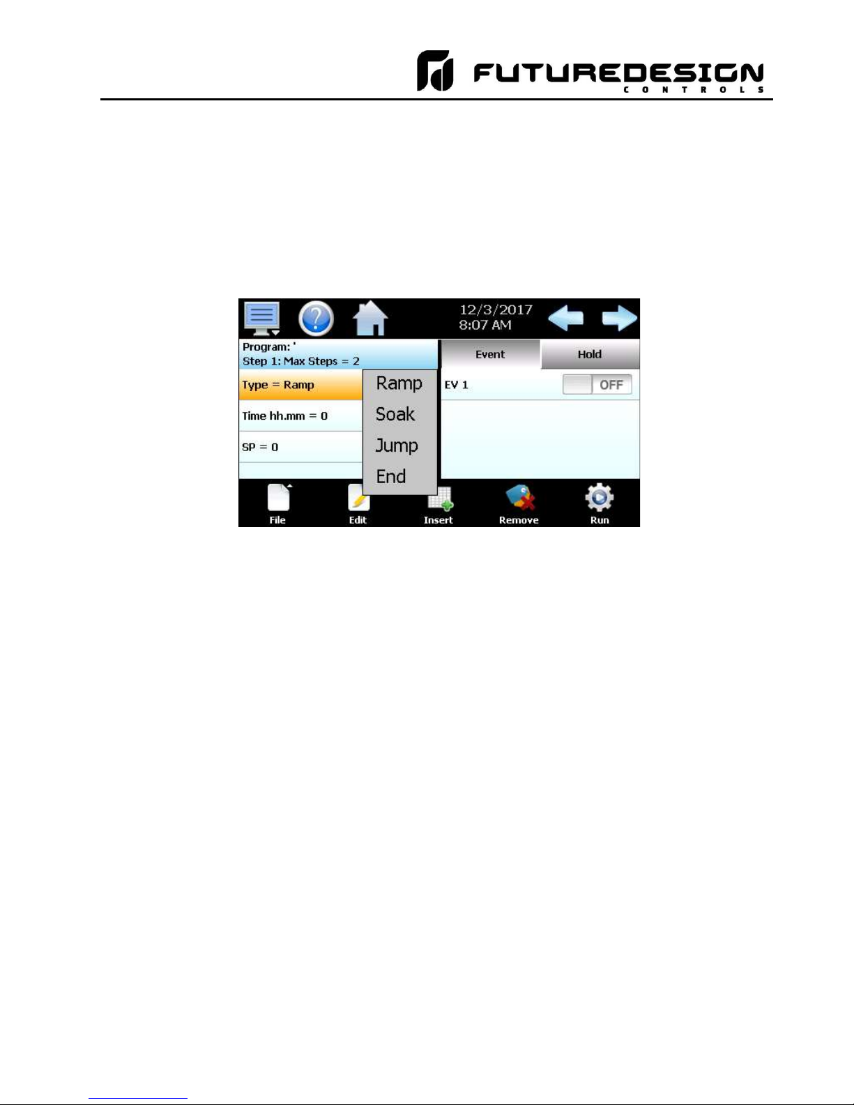
MCT-MC 4.3
6.1.1 Setting Step Type
Programs are entered as a sequence of steps which define the set point and length of time that a loop should
take to reach the set point (ramp) or remain at a set point (soak). The ramp and soak units can both be set for
hours/minutes or minutes/seconds or one can be set for hours/minutes while the other is set for
minutes/seconds. To begin editing a program step, first select the type of step by pressing the first row in the
list and make the desired selection from the step type pop-up menu.
NOTE: As the step type selection is changed, the list will update to include only the items specific to the
selected step type. This simplifies step entry by only requesting user entry for the items necessary
for proper step operation.
The Ramp selection allows the user to program the loop to ramp to a set point in a specific period of time.
Simply select ramp from the pop-up menu and then enter the loop set point and time.
The Soak selection allows the user to program the loop to maintain its set point for a specific period of time.
Simply select soak from the pop-up menu and then enter the time desired to maintain the set point.
The Jump selection allows the user to jump to a previous step in the program and set the number of times
the program should execute the jump before continuing to the following step of the program.
The End selection allows the user to program the last step of the program. The end step type includes a final
set point (if configured) and a cycle count entry to allow the user to enter the number of cycles the program
should repeat itself if desired.
6.1.2 Setting Step Set Point and Time
Set point entry is only provided when entering a ramp step. If “soak” is selected for the step type, the loop will
remain at the previous set point for the amount of time entered for the step. The set point entered is used as
the target set point for the step, i.e., the set point the loop control will arrive at by the end of the step.
To enter the set point, touch the set point field and enter the desired set point. The limits of entry will be
dependent upon the selected primary loop under the Program Operation window Settings. To enter the step
time, touch the time field to enter in the desired time duration. Time is entered as HH.MM or MM.SS depending
upon the selection made on the Time setup screen under the Edit icon pop-up menu. Thus, to enter a time of
1 hour for example, you would enter a value of 1.00 for one hour and zero minutes. To enter a step time of 30
minutes, the time entry would be made as 0.30 for 30 minutes. If the time selection was in minutes and seconds,
an entry of 1 minute and 30 seconds would be made as 1.30.
Automatic Program Operation - 65 - FDC MCT-MC
Page 66

MCT-MC 4.3
NOTE: A step time of zero can be entered for a step to implement an immediate set point change. When
coupled with a hold back condition on the following step, there is no need to know the time it takes
for the process to reach set point. The hold back condition can be used to trigger the next step,
typically a soak, so that the desired soak time is achieved without having to determine what additional
time may be needed in order to make sure that the process reaches set point before starting the soak
time.
If the ramp units are set for units/hour or units/minute (instead of time), ramp steps are entered as a rate of
change in process units/time period. If a set point is entered for the step that matches the set point of the
previous step, the step will be skipped since the loop is already at set point.
6.1.2.1 Ramp/Soak Time Units Selection
The Time selection screen is accessed by selecting the “Time” menu item from the Edit pop-up menu. The
ramp and soak time selections both provide the option of hours and minutes (hh.mm) and minutes and seconds
(mm.ss). In addition, the ramp time selections include units/minute (u/min) and units/hour (u/hr). The selections
apply to all steps of the program. The time units can be changed at any time during program entry; however,
the time entry of each step is not scaled to the new unit selection when the change is made.
FDC MCT-MC - 66 - Automatic Program Operation
Page 67

MCT-MC 4.3
If a ramp step was entered in the previous selection of “u/hr” for example, a ramp rate entry of 10 degrees per
hour will become 10 degrees per minute if the ramp selection is changes to “u/min”. When time unit selections
are changed, all steps must be reviewed in order to make sure the actual ramp rate or time length for each step
is set to the desired length.
6.1.3 Setting Step Events
For each step of the program, the user can select which events are to be on during the step. To edit step
events, press the “Event” button on the program Entry screen. This will display the Event list for the program
step.
When at least one event is
turned on in a step, an
asterisk ‘*’ will appear before
the word “Event” on the list
selection button.
This indicates that at least
one event is turned on
without having to press the
“Event” button.
IMPORTANT: The events displayed on the program entry events screen are those configured for the “primary”
loop, whether the program mode is set to “Single” or “All”. To view events for a specific loop,
set the primary loop under the Program Operation window Settings to the desired loop you
wish to create the program for. While a program can be downloaded and run on any loop in
the system, if the event selections do not match the configuration of the loop (events assigned
to different outputs), the event output will not turn on when the program is run.
The desired event state for the step can then be set by pressing the on/off button for each event to toggle them
on and off. Events cannot be set for the End step. During program operation, when the End step is reached,
the event outputs will return to their previous static setting (prior to starting program operation). If the loop
control is configured for “Final SetPoint” at end of program operation, the program will remain in the end step
state and all event outputs will turn off until the user halts program operation. Upon stopping the program, the
event outputs will then return to their static settings.
Automatic Program Operation - 67 - FDC MCT-MC
Page 68

MCT-MC 4.3
NOTE: The step events must be set individually for each step. Even though a ramp/soak program may be in
operation, if the events are not set, the associated loop control output will not turn on. To make setting
step events quick and easy, the MC provides the “Step Events” function from the “Edit” menu. When
selected, all event selections of the current step will be copied to all following steps.
6.1.4 Setting Hold Events
The hold event is used to turn on the holdback option for the loop control. To edit the hold event, press the
“Hold” button on the program Entry screen. This will display the Hold list for the program step.
When the event is turned on
in a step, an asterisk ‘*’ will
appear before the word
“Hold” on the list selection
button.
This indicates that holdback
is enabled without having to
press the “Hold” button to
display the holdback event
list.
Pressing the on/off button will toggle holdback on and off for the loop. When the hold event is enabled, the
program will automatically enter a hold condition during the step if the loop’s process value deviates from its
set point by more than the holdback limit setting for the program.
NOTE: When running an automatic program in the “All” mode, only the primary loop is monitored for the
holdback condition. All additional (slave) loops are not monitored for holdback. If there is a need to
monitor the slave loops and place the program in hold if they deviate too far from set point, it will be
necessary to configure the slave loops with deviation alarm outputs.
The deviation alarm outputs can then be wired into the event input of the primary loop. With the event
input of the primary loop configured as an “automatic program hold” input, the program running in the
primary loop will be placed in hold whenever a slave loop deviates too far from set point. When the
deviation alarm deactivates, the program will then resume operation. Note that the deviation alarm
set points for each loop will have to be manually entered to match the holdback limit as set in the
running program.
6.1.4.1 HoldBack Limits
The holdback limit setting is used to set the control tolerance for the loop during steps that have hold back
enabled. When the loop process variable deviates from its set point by more than the band value (above or
below set point), the program timer will stop until the process variable re-enters the hold back band. The
Holdback Limits are accessed from the Edit pop-up menu. The entry applies to every step in the program and
only needs to be entered once for the program.
FDC MCT-MC - 68 - Automatic Program Operation
Page 69

MCT-MC 4.3
The MC uses “band” type holdback operations. This means the MC will be in hold mode when the loop process
value is above or below the loop set point by the entered holdback limit value during step operation.
6.1.5 Setting Jump Steps
This feature allows the program to jump back to a previous step in order to repeat certain sections of a program.
When a jump step is entered, the program will jump to the specified “jump step” rather than continuing on to
the next step in the program. After all of the programmed jump cycles have been completed, the program will
then continue to the following step without making any further jumps.
NOTE: The MC has the ability to do nested looping, i.e., allowing multiple jump steps to be programmed
throughout a program in which one jump cycle is repeated within another jump cycle. The program
Status screen will display the current cycle count; however, this is for the outer most jump step. If
nested jump loops are programmed, the cycle count of the inner jump loops is not displayed.
To program a jump step, select jump for the step type and enter the step number that you want the program to
jump back to along with the total number of times the jump is to be made (by pressing each row in the list). A
cycle count of one indicates that no jump will be made since one cycle is completed upon reaching the jump
step.
Automatic Program Operation - 69 - FDC MCT-MC
Page 70

MCT-MC 4.3
6.1.6 Setting the End Step
All programs require that the last step is entered as an “End” step type regardless of the length (2 to 64 steps)
of the program. The end step type provides a cycle count entry which makes it easy for the operator to repeat
an entire program without having to enter a jump step. The end step cycle count can be set from 1 to 9999
cycles. An entry of 10,000 can also be made which signifies infinite looping, i.e., the program will keep repeating
itself until manually stopped by the user. Press each row in the list to make the desired entry.
If the MC is configured for automatic program final set point entry, the loop set point will be displayed in the list.
When the program ends, the set point entered on the end step will be used as the loop set point. The loop
control will then remain at that set point until the user halts the program. One the program is stopped, the loop
control will then return to the previous static set point (prior to the start of the program).
The MC configuration also provides the option for having the loop controls return to the static mode of operation
when the program is completed. When configured to use the last control set point, the loop controls will
automatically return to the previous static set point (prior to the start of the program) when the program ends.
If there are questions or concerns about the configuration and operation of your MC controller, contact your
OEM for further information. Only your OEM can address equipment related issues.
NOTE: When configured for automatic program final set point entry, the MC will remain in the end step until
the user manually stops the program. If any loop control outputs are configured as events, they will
remain in the off state and cannot be turned back on until the program is stopped.
FDC MCT-MC - 70 - Automatic Program Operation
Page 71

MCT-MC 4.3
6.2 Starting an Automatic Ramp/Soak Program
All automated program operating functions are accessed via the Program Operation screen. This screen can
be accessed by pressing the “Program Operation” button on the Loop view screen or by pressing the “Run”
button on the program Entry screen.
The program operation allows an operator to run, hold, stop, edit and select automatic programs. The Program
Operation window will display the program status of the selected loop for which the Run, Hold and Stop buttons
can be pressed in order to perform the desired action. Selecting a different loop from the drop down menu will
switch status/control of program operation to the loop selected. If the program mode is set to “All”, the loop
selection will default to the primary loop and no other loop can be selected.
When the Run button is pressed and a program is already loaded in the selected loop, the user can start the
program without entering a start step. This offers a quick start/stop of programs for repetitive test operations.
In this case, the program will always start from step 1. If there is the need to start the program on a different
step, press the “Select” button and choose the program from the list, then press the Run button. This will display
the Start Step entry.
The Start Step can be adjusted up and down by pressing the right/left arrow buttons or by pressing the step
number field and directly entering the desired start step via the numeric keypad. Once the desired start step
number is entered, press the “Start” button. The program will then be transferred to the loop control and started
once the transfer is complete.
Automatic Program Operation - 71 - FDC MCT-MC
Page 72

MCT-MC 4.3
To stop a program, select “Stop” from the Program Operation window. When a program is stopped, the loop
set point and events will revert back to the single set point (static mode) values that were entered prior to the
program being started. Pressing the Edit icon will navigate directly to the program Entry screen so a program
can be created, edited and stored.
6.2.1 Hold/Resume Ramp/Soak Program Operation
At any time during the operation of a program, it can be manually placed into hold. This stops the program
timer; however, the MC continues operation under the current step settings at the time the program was put
into hold. To pause a program, select “Hold” from the Program menu. To resume the program from the point
in which it was paused, select “Start” from the Program menu.
NOTE: The program will automatically be placed in hold if holdback is enabled for the step and the process
value of the selected loop deviates from set point by more than the holdback band. When the program
is in holdback, it can not be resumed by pressing the Run button. The program will automatically
resume once the process value of the selected “hold loop(s)” is within the holdback band from set point.
6.2.2 Program Mode Settings
The program settings are used to select the mode of operation for the automatic ramp/soak programs. The
program Settings screen is accessed from the Program Operation window by pressing the “Settings” icon.
The Primary loop selection is used to select which loop is to be used as the master loop when operating under
the “All” program mode. It is also used by the program Entry screen to default the range of the set point limit
entry and event selections.
The Single mode selection button allows each control loop to run independently of the others. Programs are
then downloaded separately to each loop control. The user can then individually start and stop the program in
each loop control. Any combination of loop controls can then be operated in single set point (static) mode or
automatically via the program at any given time.
The All mode selection button links all loop controls into a master/slave program operation. While in single set
point (static) mode, each loop control operates independently from the others. However, when an automatic
program is started, the loop defined as the “Primary” loop becomes the master and all other loops become set
point slaves. As the program runs on the master loop, the set point of all slave loops will be set to match the
set point of the primary loop for the duration of the program’s operation.
The user will be unable to manually change the loop set points of the slave loops during program operation.
However, any events tied to the slave loops can be manually turned on and off during program operation. Only
events tied to the primary loop will be controlled via the automatic ramp/soak program.
FDC MCT-MC - 72 - Automatic Program Operation
Page 73
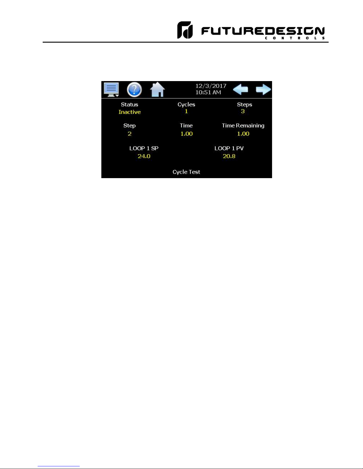
MCT-MC 4.3
6.3 Monitoring Automated Ramp/Soak Program Operation
The program Status view provides all information regarding the operation of a program for each control loop
configured in the system.
The Status field indicates the current operating mode of the program, i.e., On, In Hold and Off.
The Cycles field indicates the number of cycles left to be completed for the current jump loop.
The Steps field indicates the total number of steps in the current program.
The Step field indicates the step number currently being executed.
The Time field indicates the total length of time programmed for the current step.
Time Remaining is the time remaining in the current step.
The loop SP indicates the programmed set point for the loop that will be achieved by the end of the step. The
field will indicate the current ramp or soak status for the loop based on the set point of the step. If the target
set point of the step is greater than the loop set point, “ramp up to” will be displayed. If the set point is lower
than the current loop set point, “ramping down to” will be displayed. If the step is a soak step or the target set
point is the same as the current loop set point, “soak at” will be displayed.
The loop PV displays the current process value of the loop.
The name of the running program, or current program loaded to the loop control, will be shown at the bottom
center of the screen. If no program has been loaded, the field will be empty.
IMPORTANT: If the set point does not match the set point programmed for the step, check the lower and
upper set point limits for the loop (see Section 9.3 Setpoint Limits). The lower and upper limits
define the allowed operating range. If a step set point exceeds a limit, it will be coerced to the
lower or upper limit that it exceeds. This is done automatically without altering the original
program.
Automatic Program Operation - 73 - FDC MCT-MC
Page 74

MCT-MC 4.3
6.4 Common Questions About Ramp/Soak Program Operation
1. How do I start or run a ramp/soak program?
To select and start a program, use the Program Operation window which can be accessed from the Loop view
and program Entry screens. All start, stop and hold operations, program edit and select and program settings
are available from this windows.
2. How do I know which program is running?
When a program is running, the name is displayed on program Status view screen as well as the Loop and
Overview screens. It is also shown on the Program Operation window. The MC will indicate that the program
is running when it is in operation. If a program is not running, the MC will display the name of the currently
loaded program, i.e., present in memory and ready to be run.
3 Why is the program not running to the set point entered for the step?
Automatic ramp/soak program operation is limited by the lower and upper set point limits (see section 9.3
Setpoint Limits). If a program step has a set point that exceeds the lower or upper limit, the set point will be
automatically coerced to the limit it exceeds. This prevents damage to equipment or product by insuring that
the system only operates to the range entered by the user. If a program step has a set point of 100 for example,
but the upper limit is 90, when the program is run the set point will be coerced to the maximum allowed upper
limit of 90 during operation of the step.
The original program remains unaltered, so if the user then changes the lower and upper limits to match the
range of set points within the program, the program will then operate to the programmed set points. This insures
that the operating range of the system cannot be exceeded even if a user accidentally copies a program from
another system with a greater operating range.
FDC MCT-MC - 74 - Automatic Program Operation
Page 75

MCT-MC 4.3
7 Security
The MC security model provides an administrator with the tools to add up to 30 users to the system. Each user
must have a unique ID, full name and password. Four user levels are provided which include system, user,
supervisor and administrator levels. Specific access rights can be assigned to each user level and password
aging can be implemented. Verification is provided (if enabled) for any parameters that will change a control
parameter, which could upset the process (i.e. loop set point, start/stop automated ramp/soak programs, etc).
Verification requires that the logged in user must log in again before the process value (at the controller) will
actually be changed. This feature is provided for extra security. The following example will make reauthentication clearer:
A supervisor logs on the system. The supervisor then steps away from the system to take a phone call but
does not log out before leaving. If another user tries to change the control set point on any loop, the system
will require another login (by an authorized user for that level) before the control set point is actually changed.
This provides an extra level of protection to make the system more “tamper proof”.
The Security menu is accessed from the home menu and provides access to the security section of the MC.
The Security menu provides the following functions:
Configure Provides access to security setup to add users, set rights and options.
Login Log on a user if security is enabled.
Log Off Log off a user if security is enabled.
Audit Allows the user to view any of the saved audit trail files.
User Shows the current user logged into the system.
Password Allows the current user to change their password.
Security - 75 - FDC MCT-MC
Page 76

MCT-MC 4.3
7.1 Adding Users
The “New” user tab provides the ability to add up to 30 users to the system. Select the type of user from the
drop down list (System, User, Supervisor or Administrator). Press each field to add the user ID, full name and
password (no spaces allowed, 5 character minimum and 16 characters maximum). Press the “Create” button
to add the user to the system. If the passwords do not match or the user ID is already used, the MC will alert
the user and not accept the entry.
7.2 Viewing Users
The “Users” tab provides the administrator with the ability to view information on each user entered into the
system. Password information is not available. The user can be deleted from this tab and a new password for
each user can also be entered from this area.
To delete a user, select the user from the list and press the “Delete” button. Likewise, to change the password
for a user, select the user from the list and press the “Password” button.
7.2.1 New Password Entry
To change a password, select the desired user by touching the User ID in the list box and press the ‘New
Password’ button. Enter the new password and confirm the password. Press the “Accept” button to change
the password (no spaces allowed, 5 character minimum and 16 characters maximum).
FDC MCT-MC - 76 - Security
Page 77

MCT-MC 4.3
ramp/soak program
(does not apply to
loop
alarms)
button
Device/Setting
s
/View/Tuning
; A/M button
7.3 Setting User Access
The “Access” tab provides the administrator the ability to assign rights to each user level (System, User,
Supervisor and Administrator). To enable or disable specific program functions (user rights) for each user level,
select the user right from the list and press the corresponding on/off button for the user level you want to change
access rights for. If the button is set to on, user access will be enabled for the user group.
User access for “Security” cannot be disabled for the administrator group. This is a safety feature to make sure
that any administrator with the proper user ID and password can access security. If the administrator losses
his/her ID or password, there is no “back door” to the system and it will have to be reset and reprogrammed in
order to return to normal operation.
7.3.1 Security System User Access
Shown below is a list of the available user rights, where to find the menu item(s) applicable to the user right and
a description of what it applies to. Note that the OEM configuration allows many menu items to be disabled; in
which case the menu for a specific user right may not be shown.
User Right Menu Location Description
Setpoint Edit View/Loop, Overview applies to loop controls when not running an automatic
Events View/Loop, Overview; Manual Operation
Manual Mode View/Loop
Security - 77 - FDC MCT-MC
applies to enable or disable manual events
enable or disable loop control manual mode
Page 78

MCT-MC 4.3
Auto Tune
Device/Settings/View/Tuning
enable or disable loop control Auto
matic Tune
button
affect digital Inputs configured for same action
when power lost & recovery:
Reset Alarms
View/Alarm
alarm Reset button
Clear Alarms
View/Alarm; Clear button
prevents alarm list view from being cleared
Chart Settings
View/
Chart configure plot channels, scale & time for
charts
Data Data/Data
applies
to all data logging actions & settings
Annotation
Data
/View/
Annotation
access to add
operator messages
to active log file
Signature
Data
/View/Signature
access to add digital signature to active historical data file
Open see description
alarm,
automatic
program
, audit &
data files
from system with
USB f
ile
transfer u
tilities
deleted with File Utilities
can't insert/delete/copy/paste step.
program & audit trail files & to import
programs
FTP/WAN Data
/Utilities/FTP/WAN
configure FTP client settings
Communications
Device/Settings
/
Set/Comms
configure web page, Modbus address & VNC settings
Tuning
Device/Settings/View
/Tuning
manual adjustment of loop tuning parameters
Setpoint
Limits
Device/Settings/
Set/Limit
applies to loop controls
Adjust Alarms
Device/Settings/
Set/Alarm
applies to all loop and monitor point alarms
program
step
Events)
Email
Settings
Device/Settings/
Email/Email Settings
configure email settings and addresses
Email
Message
Device/Settings/Email/Message
access to compose & send email message
Offset,
Configuration
C
alibrat
e Touch
Device/Settings/
Offline/System/Display
access to
the touch screen calibration utility
delay time
Alarm Volume
Device/Settings/
Offline/System
/Display
allows edit of
MC alarm beeper volume
Units Device/Settings/
/Offline/Set/
Units loop/monitor point temperature units configuration
- C\F Clock
Device/Settings/
Offline/Set
/Clock
Set Date/Time, Time Zone, DST and NTS connection
NTP Device/Settings/Offline/Set/Clock
enable & choose National Time Server location
D
aylight Savings
Device/Settings/Offline/Set/Clock
enable Daylight Savings Time (DST)
Language
Device/
Settings/
Offline/Set/
Language
Select help language
Security
View/
Security/
Configure
applies to Security Setup
Configuration
button
startup).” bu
tton
startup).”
button
loop inputs.
User Right Menu Location Description
Program Operate Program/Run, Hold, Stop actions applies to all program control menu selections; does not
Recovery Device/Settings/Offline/Set/Recovery logic when running an automated ramp/soak program
Save see description program “save” and “save as”; note files may be copied
Delete see description data files & automatic programs; note files may be
Program Edit Program/Entry no data entry or access to Events or Step SP/Time fields;
USB Data/Utilities/USB allows USB memory stick to copy/delete data, alarm,
Event Names Device/Settings/Set/Event configure event tagnames (seen in manual Events &
Offline Device/Settings/Offline access to Off-Line menu system: Units, set Clock,
Backlight Device/Settings/Offline/System/Display access to edit backlight settings for brightness and off
Configuration Device/Settings/Offline/System/
Configuration
Default Configuration Device/Settings/Offline/System/
Configuration; Reset Default
Exit (run mode) Device/Settings /Offline/System/Exit;
“Exit application. (automatic mode
Exit to Configurator Device/Settings /Offline/System/Exit;
“Exit Application. (configuration mode
Calibrate Touch, Language, Exit To Application, input
access to import/export setup files of MC
function to clear system configuration and reset all to
blank (default) state for reconfiguring
prevents MC application from being stopped
prevents MC application from being stopped and access
to the MC configurator application
Calibrate Inputs Device/Settings/Offline/Calibrate Provides user offset calibration or full calibration of all MC
FDC MCT-MC - 78 - Security
Page 79

MCT-MC 4.3
7.4 Setting Security Options
The security “Options” tab provides the administrator the ability to set the global security options.
The Password Aging Days field is a global for all users. Password aging starts from the day the user is
entered into the system. The value can be set from 0 to 365 days. A value of zero disables password aging.
NOTE: When using password aging and the password expires for a user, the user will be required to change
their password before access to the system is permitted. A user can change their password at any
time (even if aging is not used) by selecting “Password” from the main security menu.
When enabled, Verification requires that the logged in user must log in again before the entry value will actually
be changed.
Audit is a global setting that turns the audit trail on or off. When the audit trail is turned on, all user actions are
written to a daily log.
Security is the global setting that turns the MC security system on or off. The security system must be enabled
for the audit trail to be enabled.
Security - 79 - FDC MCT-MC
Page 80

MCT-MC 4.3
7.5 Audit Trail
The audit trail viewer is accessed by selecting “Audit” from the Security menu. It displays all user actions that
affected the system for any given day. The MC can store daily audit files for a period of a year or longer (time
based on storage usage for data history). Each time a user take an action that affect the operation of the
system (changing a set point, start/stop data logging, changes an alarm set point, etc.), the action is written to
a file. Audit trail file names are listed as month_day_year. The “Open” file button will display a dialog box
where the user can select any audit file to view.
NOTE: If no actions occurred on a given day, an audit file will not be created for that day.
Each action recorded to the file includes the date/time it occurred as well as the user (if logged in) that made
the change. If no user is logged in, the user will be listed as “Device Manager”, which is the default user account
for the MC system.
The send email icon allows the user to send a copy of the currently opened audit trail file to any user
configured in the MC. When the email icon is pressed, an “Add Recipients” window will be displayed where the
user can select recipients for the file from any of the email addresses configured under the MC email settings.
For information on how to add email recipients to the MC, see the section 9.9, Email.
FDC MCT-MC - 80 - Security
Page 81

MCT-MC 4.3
8 Data Logging
The MC data logging features are accessed via the home ‘Data” menu item. The system data logging provides
the ability to select individual points for logging, view data log files and start/stop logging operations. The
logging ability of the MC provides an easy-to-use, convenient method to obtain electronic data without the need
for additional data acquisition equipment.
The Data Log menu provides navigation to the following functions:
View menu
Annotation: Allows the user to insert a notification into the currently
running log file or view all annotations associated with the
currently loaded historical data file.
Signature: Allows the user to digitally sign a file to prevent data
tampering and view all digital signatures associated with the
File menu
Open: Opens a history file for review.
Delete: Allows the user to delete the currently loaded history file.
Data menu
Data: Displays main data log screen with status of logger.
Assign: Allows the user to select what variables are to be logged.
Chart menu
Set: Selection of data file points and time period for history review.
Chart: Plots historical data after time and points are selected.
Utilities menu
USB: Allows the user to access file utility functions.
FTP/WAN: Provides access to the automatic file back-up settings.
Memory: Displays memory capacity remaining on MC.
currently loaded historical data file.
NOTE: The “Delete” log file function does not affect data from a
file that is running, only the current data log file loaded
for review.
Logging - 81 - FDC MCT-MC
Page 82
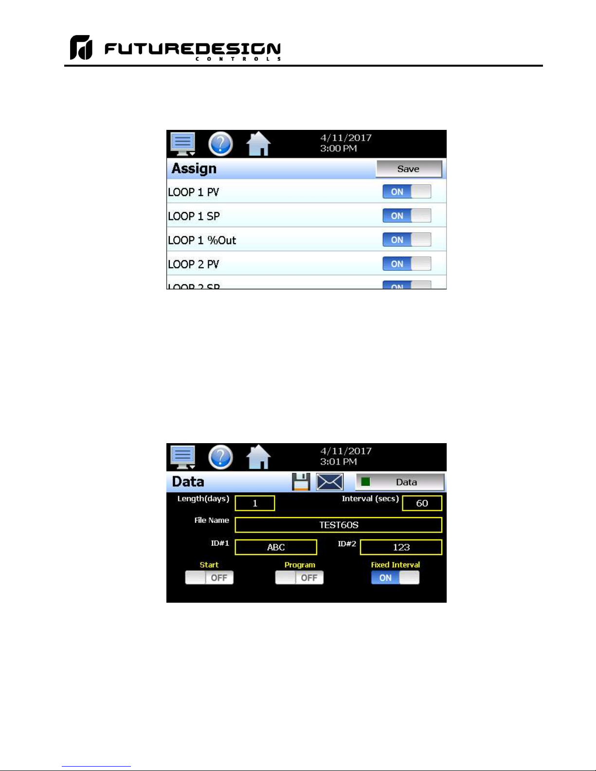
MCT-MC 4.3
8.1 Selecting Points for Logging
In order for the data logging function of the MC to operate, the user must first select what variables are to be
logged to the data file. To choose which points are to be logged, select “Assign” from the Data menu.
Press the on/off button for each item to toggle it on/off. W hen on, the variable will be logged to the data file.
When selections are completed, press the “Save” button to save the point selection to memory. New selections
will not take effect until the Save button is pressed.
8.2 Starting/Stopping Data Logging
The MC logs data to its SD card. Current data for each variable is written to the log at a fixed interval based
on the settings entered in the “Length” and “Interval” fields. File names are automatically generated using
mm_dd_yyyy_hh_mm_ss format. To use a specific file name, touch the “File Name” field and enter the desired
name (up to 16 characters). When a file name is entered, the file will be saved as
FileName_mm_dd_yyyy_hh_mm_ss.
The data logger also provides two entry fields, ID#1 and ID#2, which allow the user to enter in information
specific to the file such as a batch and/or lot number to identify product that may be associated with the new
data file. These entries will be saved with the data log file for later identification.
The Length (days) field sets the length of a data file in number of days. It can be set for 1 to 31 days. Once
the selected number of days has elapsed, a new data file will be created and logging will continue in the new
file.
FDC MCT-MC - 82 - Logging
Page 83

MCT-MC 4.3
The Interval (secs) field is used to set the rate at which points are written to the log file which equates to the
sample rate in seconds. When the “Fixed Interval” option is turned on, the logging interval will be automatically
set to record at minute intervals based on the number of days set for the file. If the file is set for 1 day in length,
the logging rate will be at 1 minute intervals. If the file is set for 7 days, then the logging rate will be every 7
minutes. This keeps the data file size manageable and able to be viewed by the MC data viewer.
The log interval can be manually set to any rate between 1 and 1860 seconds in any combination with the
number of days before a new file is started. To do this, turn off the “Fixed Interval” option and enter in the
desired logging rate in seconds.
NOTE: Logging at shorter intervals allows the MC to capture fast changing processes, but the data files can
become extremely large. Files that exceed the capability of the MC data viewer (>520KB in size) will
have to be extracted from the MC using a USB memory stick or FTP file transfer in order to be viewed
remotely on a PC.
Files larger than the 520KB limit will not be automatically, digitally signed by the MC. If the files are to
be digitally signed, this must be done manually by extracting the files and using the FDC data viewer
program running on a remote PC.
To manually start data logging, press the “Data” button. Any time logging is enabled, the indicator on the Data
button will be illuminated. To stop data logging, press the Data button again. Data logging can also be started
automatically by turning on the “Start” or “Program” option.
The Start option automatically turns data logging on whenever the MC is first powered on. This action simulates
that of a standard chart recorder.
The Program option is a convenient method for gathering information that pertains only to the operation of an
automatic ramp/soak program. When selected, the MC will turn the data logger on at the beginning of a program
and off once the program is completed. This eliminates the need to scan through extensive data records to find
the specific information you are looking for from a particular time period.
NOTE: When more than one loop is configured and the program operating mode is set to “Single”, data
logging will start when a program is started on any of the loop controls. If more than one loop is
running a program, all of them must then be stopped before data logging will be stopped.
The Email icon next to the data log on/off button allows the user to select the currently open data file and email
the file to any user that has been setup to receive emails from the MC.
The Disk icon next to the Email icon allows the user to save the currently opened data file to a USB memory
device connected to the MC.
8.2.1 Calculating Log File Size
The MC saves the log file in a text based format (.csv), so the amount of memory consumed for each reading
is dependant upon the number of digits required to accurately display the value. This optimizes memory usage
but also makes calculating an exact file size difficult. To obtain a worst case approximation of the resultant file
size, use the following formula:
File Size (KB) = 1 + [0.023 + (0.006 * number of log points)] * number of readings
Logging - 83 - FDC MCT-MC
Page 84
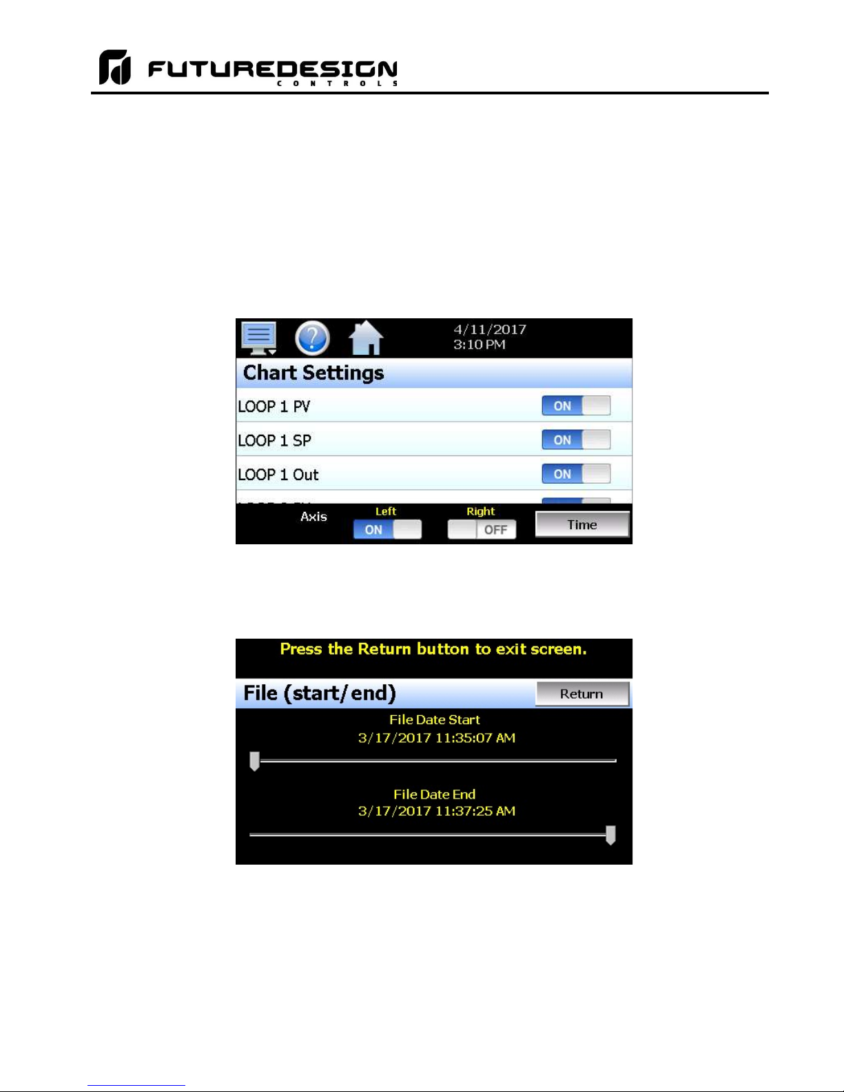
MCT-MC 4.3
8.3 Reviewing Historical Data
Historical files can be opened and viewed using the historical viewer. In order to view a historical data file, it
must first be opened by selecting “Open” from the File menu. Once the file has been opened, the MC can
automatically plot the first eight channels of the historical data file or the user can choose to cancel the plot and
select which channels should be plotted as well as adjust the specific time period to plot.
8.3.1 History Plot Setup
The history plot setup allows the user to select any time frame (zoom in/out) from the historical data file as well
as select up to six channels of data to plot. To edit the settings for the historical plot, select “Set” from the Chart
menu.
Any point from the data file can be selected along with the vertical axis to be used for each channel to be plotted.
Select channels from the list by turning them on or off, and use the “Left” and “Right” axis buttons to assign the
selected item to the left or right axis for the plot range. To adjust the period of time to plot from the data file,
press the “Time” button.
The start and end dates for the currently loaded file will be shown with time in hours, minutes and seconds.
The “File Date Start” and “File Date End” sliders are used to select a time span for historical viewing. Once the
desired start and end times have been set, press the “Return” button to return to the Chart Settings screen.
8.3.2 Plotting Historical Data
The history Chart plots the data from the currently opened history file according to the selections made under
chart setup. If a file has not been opened or data points have not been assigned to a plot, the MC will alert the
FDC MCT-MC - 84 - Logging
Page 85
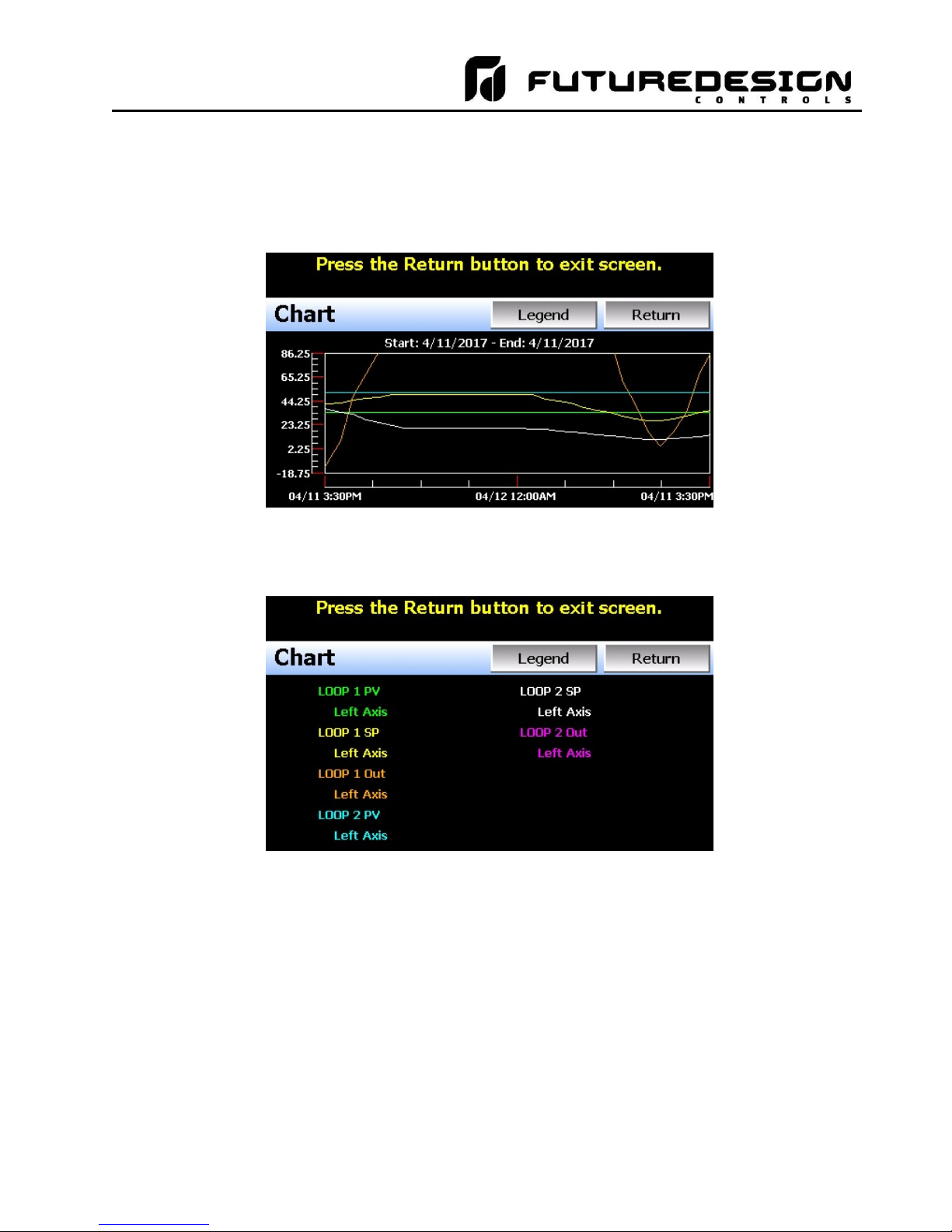
MCT-MC 4.3
user to correct the problem. The ‘X’ and ‘Y’ axis scales are set to auto scale based on current values for each
plot channel so no user action is required.
The historical graph provides the same zoom feature as the real-time charts so the user can zoom in on a
particular area of the historical plot by dragging their finger across the screen to draw a rectangle around the
desired plot area.
Pressing the “Legend” button will provide the user with channel information by displaying the names of the
selected plot channels, which axis they are associated with and the color used to display the plot channel.
Pressing the button again will toggle the display back to the historical chart.
NOTE: When pressing the Legend button to toggle between the historical chart and the legend screen, it may
take several seconds for the chart to become visible depending on the size of the data file and number
of channels selected to plot.
When finished viewing the historical chart, you must press the “Return” button to exit the historical
data viewer and return to the main data log screen.
Logging - 85 - FDC MCT-MC
Page 86

MCT-MC 4.3
8.4 USB File Transfer
A quick note about file storage; data and setup files (programs, alarm log and audit trail files) need some
maintenance every now and then. After a period of time, storage devices fill up and files require backup or file
deletion when no longer needed. The “Utilities” section of the MC interface provides all the functionality required
for maintaining the internal SD memory card. The internal SD card should not be removed from the MC
interface. Any change to SD directory structure (moving or deleting files with a PC) may cause the MC interface
to stop operating and a new SD card will need to be ordered. Never move or delete the directories unless using
the provided MC file utilities functions.
NOTE: The data log files, programs, alarm log and audit trail directories are saved to the internal SD card
(not the USB memory stick device) plugged into the MC interface. Never unplug the SD card when
the MC is powered up or loss of data may result.
The USB file transfer screen allows the user to copy or erase files from the internal SD card. Complete file
directories for all MC file types can be copied to the USB memory stick and erased from the internal SD card.
The current status for file functions is displayed for the operator during copy/delete operations. The MC also
allows automatic programs to be imported from the USB memory stick. Programs must be exported from
another MC device to the memory stick first, before this function can be used. The MC will look for “Program”
directories on the memory stick for import and alert the user if none exist.
NOTE: All file transfer functions can be used while data logging is running. If the operator needs to back up
or delete files from the system, a large number of files could take considerable time to backup and
delete from memory. The file transfer screen will be locked during file transfer so plan the timing
appropriately when access to other screen functions is not required.
When data logging is running, the current data log file will not be copied or deleted while using the
file transfer functions. This protects the current file and makes sure that the data file is complete
before being copied and cannot be deleted from memory while it is still in operation.
To Copy files, insert the USB memory stick into the USB port. Select the file type you wish to copy from the
“Export Type” drop down menu. Available file selections are Program, Alarm, Audit and Data files. Once the
selection is made, press the “Copy” button. All related files will be copied to the USB memory stick with progress
status displayed to user.
To Copy/Delete files from internal memory, insert the USB memory stick into the USB port. Select the file type
you wish to copy and erase from the MC internal memory by selecting it from the “Export Type” drop down
menu. Available file selections are Program files, Alarm files, Audit trail files and Data files. Once the selection
is made, press the “Copy/Delete” button. All related files will be copied to the USB memory stick and then
deleted from the MC with progress status displayed to user.
FDC MCT-MC - 86 - Logging
Page 87

MCT-MC 4.3
The Import file function allows automatic ramp/soak program files to be copied from the USB memory device
to the MC. A dialog box will appear listing the available program directories on the USB memory stick. Program
directory names exported from the MC are in the format ‘Programs_mm_dd_yyyy-hh_mm_ss’.
NOTE: The USB memory stick must be inserted into the USB port for any of the file utility operations to function.
It is recommended to only use memory sticks certified by Future Design Controls for use with the MC.
Future Design Controls has tested and validated these memory devices for proper operation and
performance.
Due to manufacturing variations in the USB memory sticks, it may take a few seconds up to 30 seconds
for the MC to recognize the device when it is plugged in. Allow sufficient time for the device to be
recognized before attempting any file utility operations or the MC will indicate a file transfer/memory
stick error.
When files are being copied to the USB storage device, a directory for each file type will be created to store the
copied files. The directory structure is as follows:
Program files directory: Programs_mm_dd_yyyy-hh_mm_ss
Alarm files directory: Alarm Files_mm_dd_yyyy-hh_mm_ss
Audit files directory: Audit Files_mm_dd_yyyy-hh_mm_ss
Data files directory Data Files_mm_dd_yyyy-hh_mm_ss
The purpose for using the date and time as part of the directory name, is to make sure the user can track the
date and time of the file transfer. If a user transfers a file type more than once in a single day, the files will be
grouped logically by time.
When accessing the data files saved to the USB memory stick, the data files will be in “.csv” format. These
files can be opened directly with Microsoft Excel or any program that opens a comma separated file format.
You can copy or empty the “Data Files”’ directory by simply plugging the USB device into a PC’s USB port. The
device then becomes like any removable disk attached to the computer and can be manipulated once plugged
into the PC.
The FDC Data Viewer program is a free Windows accessory program that allows users to view, plot and print
data files and is available from Future Design Controls or any manufacturer that markets the MC product. It is
required when using the digital signature feature of MC.
IMPORTANT: Once files are deleted from the MC storage devices, they are gone and cannot be retrieved.
DO NOT edit, move or delete any other files from the internal SD memory card unless using
the MC file utilities. The MC will not operate properly if the file/directory structure is altered.
‘Windows XP’ and ‘Excel’ are trademarks of the Microsoft Corporation.
Logging - 87 - FDC MCT-MC
Page 88
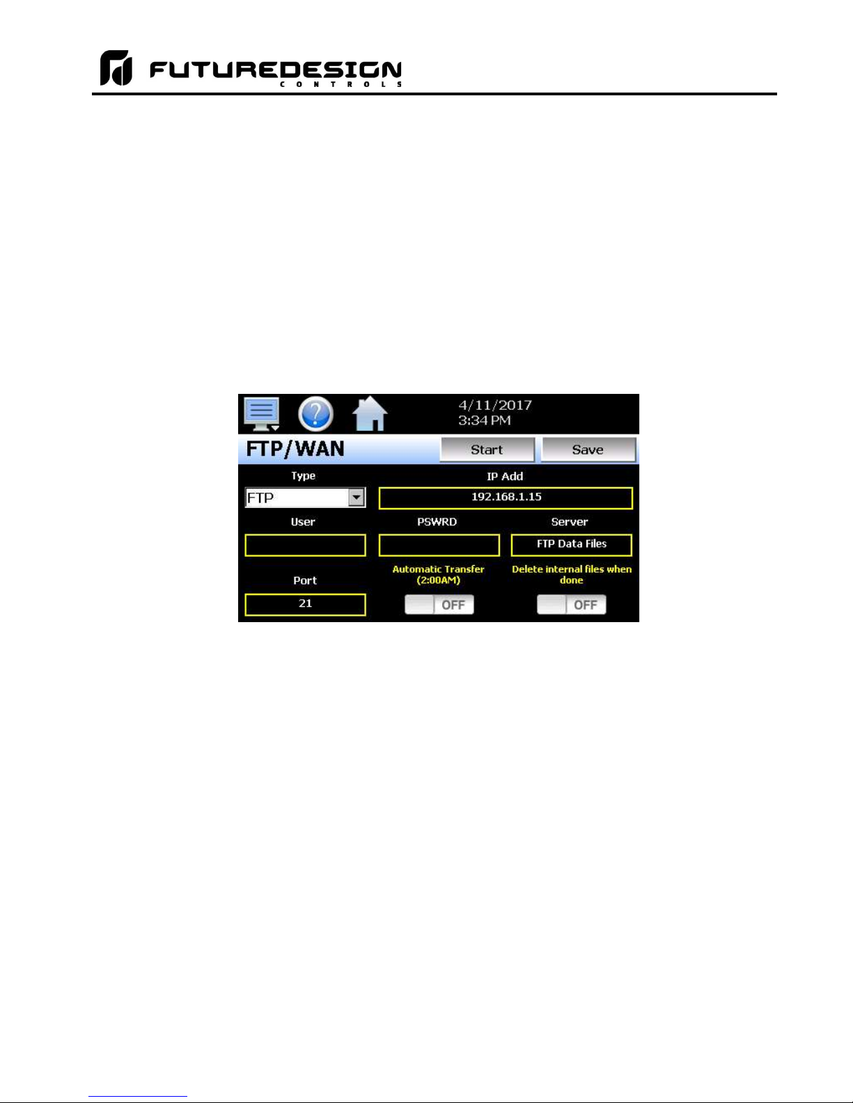
MCT-MC 4.3
8.5 FTP/FileWeb/DataWeb Interface
The FTP/WAN screen allows the user to configure automatic back-up of all data files contained in the MC
memory to a user designated FTP or secure FileWeb site (https://). When enabled, the MC will automatically
back up all data log files, alarm files and audit trail files at 2:00AM each day. With the optional delete files
selection, the MC will then automatically delete the files from its internal memory after back up. This will
maintain MC memory automatically, so that continuous data logging can be performed without filling up the
available memory space.
The MC also offers a DataWeb LAN/WAN/Cloud interface. This allows the MC to transfer data directly into a
server’s data base rather than using file based data solutions. The DataWeb interface provides the transfer of
secure (https://), real time data which can be shared and viewed across networks for real time manufacturing
data systems interface.
NOTE: Setting up an FTP site on your network may require authorization and/or assistance from your network
administrator. Contact your network administrator for proper settings and authorization from your
network server (if required) to allow the MC to connect to the designated FTP site.
The Type drop down is used to select the FTP/WAN interface. Choices are FTP, FileWeb and DataWeb.
The IP Add field is used to enter the IP address of the FTP/FileWeb/DataWeb site that MC is to interface with.
The User field allows you to enter a user name for site access. When the MC connects to the
FTP/FileWeb/DataWeb site, the user name will be used to identify the connection. If a security login is required
(FileWeb/DataWeb always require security credentials), the proper user name will have to be entered in this
field. If security is not used (FTP only), this field can be left blank (blank for anonymous login using FTP only).
FileWeb and DataWeb require a username and password.
The PSWRD (password) field is used in conjunction with the user name field and is for entering a password, so
the MC can access the site. If security is not used (FTP only), this field can be left blank (blank for anonymous
login using FTP only). FileWeb and DataWeb require a username and password.
The Server field is used to enter the server directory where the files are to be backed during FTP/FileWeb
operation. This field is not used during DataWeb interface selection. When the connection occurs, the MC will
place the historical data files in the “Sever” field directory structure when using FTP/FileWeb interfaces. The
MC will automatically create an “Alarms” directory and an “Audit” directory within the specified server directory
for backup of the alarm files and audit trail files. The “Sever” field for FTP and FileWeb must match the directory
structure setup at the server.
FDC MCT-MC - 88 - Logging
Page 89

MCT-MC 4.3
For example, if FTP or FileWeb is used and the “root” path at the server is “Files” and the MC files will be
transferred to this directory, the “Sever” field will contain the text “Files”. If there is a directory inside of the
server root “Files” directory named “unit1775” and the files will transferred to this directory, the “Server field will
contain the text “Files/unit1775”. The FTP/FileWeb operations will error and transfer will not be completed if
the “Server” field is not entered properly or does not match the FTP/FileWeb server configuration.
When the Automatic Transfer (2:00AM) option is turned on, the MC will perform an automatic backup of all
historical data files, alarm files and audit trail files contained in its internal memory to the designated
FTP/FileWeb site. Note that if data logging is currently active, the active file will not be copied. When the
DataWeb interface is used, real time data is transferred to a database rather than transferring actual files so
this option is not used and is disabled.
When the Delete internal files when done option is turned on, the MC will delete all data log files, alarm files
and audit trail files within its memory after completing the backup to the FTP site. Note that if data logging is
currently active, the active file will not be deleted. When the DataWeb interface is used, real time data is
transferred to a database rather than transferring actual files so this option is not used and is disabled.
Once all settings have been made, press the “Save” button to save the settings so that on the next power-up,
the entries will be maintained. The “Start” button can be used at any time to perform a manual data backup
using FTP or FileWeb interfaces. If the files already exist on the FTP/FileWeb site, they will be overwritten on
each subsequent backup. If the FTP/FileWeb site is down, or the MC is not connected to the network, a local
alarm message on the Alarm screen will indicate a transmission failure.
NOTE: Typically FTP/FileWeb Server connections use case sensitive alpha-numeric characters for the User
name, Password and Server directory. Contact your network administrator for proper settings.
8.5.1 More About FTP, FileWeb and DataWeb Interfaces
FTP servers (File Transfer Protocol) have been around for many years and can be installed on local or network
machines. The FTP server allows a client (MC) to transfer files from a local device to the FTP server once
installed. This allows for manual and automatic backup of data from the MC device.
MC Field Setup FTP Server Setup
FTP server setup for passive operation (see Appendix section
Type = FTP
IP Add = xxx.xxx.xxx.xxx Actual IP address of FTP server
User = userName Actual user name for login if authentication used.
Password = userPassword Actual password for login if authentication used.
Server = myFTP
Port = 21 Port used at MC and open at FTP server.
NOTE: Make sure proper permissions are set at the FTP server for access/creation of directories and
read/write access. Also check root directory structure at Server to identify the actual root that was
created for the files since there can be additional layers created by the server and displayed in the path.
A.2 FTP, FileWeb, DataWeb Requirements/Installation for
additional information).
FTP server setup with a root directory named “myFTP”. The
FTP server directory path must exist and match the MC setup
for proper operation. If there is an additional directory within
the “myFTP” root directory, its name would be appended to the
path. (i.e. myFTP/Files if a “Files” directory inside the myFTP
server root directory is the target for transfer).
Logging - 89 - FDC MCT-MC
Page 90

MCT-MC 4.3
The FileWeb interface allows the MC to transfer its files to a web site for download which can then be viewed
using a standard web browser. This interface provides the user the ability to setup a web site to store files for
local or global access without installing an FTP server. The MC supports https:// (secure) transfer of files.
MC Field Setup FileWeb Server Setup
Type = FileWeb
FileWeb server setup (see Appendix section A.2 FTP, FileWeb,
DataWeb Requirements/Installation for additional information).
IP Add = https://fdctuil.com/xxxx.svc Actual named address of FileWeb server/service.
User = userName Actual user name for login at FileWeb server (required).
Password = userPassword Actual password for login at FileWeb server (required).
FileWeb server setup with a root directory named “myFileWeb”.
The FileWeb server directory path must exist and match the MC
setup for proper operation. If there is an additional directory
Server = myFileWeb
within the “myFileWeb” root directory, its name would be
appended to the path. (i.e. myFileWeb/Files if a “Files” directory
inside the myFileWeb server root directory is the target for
transfer).
Port = 21 Port used at MC and open at FileWeb server.
NOTE: Make sure proper permissions are set at the FileWeb server for access/creation of directories and
read/write access. Also check root directory structure at Server to identify the actual root that was
created for the files since there can be additional layers created by the server and displayed in the path.
The DataWeb interface allows the MC to transfer data to a web data base service using MySQL and Microsoft
IIS as a web platform. The MC can interface directly to a local or Web data base (Cloud) thereby allowing
access to any system globally without any special “client” applications required to view the data. This allows
the MC to share data with local or global manufacturing systems by storing data directly to a manufacturing
database. The MC supports https:// (secure) transfer of data.
MC Field Setup DataWeb Server Setup
FileWeb server setup (see Appendix section A.2 FTP,
Type = DataWeb
FileWeb, DataWeb Requirements/Installation for additional
information).
IP Add = https://fdctuil.com/xxxx.svc Actual named address of DataWeb server/service.
Actual user name for login at FileWeb server (required). This
User = userName
is the directory where the database structure will reside on
the server. The MC will use this directory path for sending
data to the database.
Password = userPassword Actual password for login at DataWeb server (required).
Server = not used
The directory where the database exists uses the userName
as the default location for data storage.
Port = 21 Port used at MC and open at DataWeb server.
NOTE: An IT professional with experience is required for DataWeb server setup. Future Design Controls does
not support server side programming or setup but can offer 3rd party resources to assist with or handle
complete server side projects.
FDC MCT-MC - 90 - Logging
Page 91

MCT-MC 4.3
The DataWeb interface does not transfer complete files for backup like the FTP and FileWeb interfaces. The
DataWeb interface transfers records in real time based on the log setup interval at the MC. When logging is
started at the MC, data will begin transfer to the server side site. Data will be transferred to the server at the
beginning of logging (one record) with additional records transferred based on the rate that the MC data log
interval is set for.
If the data log interval rate is set for 60 seconds, the MC will populate the database with a single set of records
(PV, SP, %Out determined by data log/server setup) once every 60 seconds. If the data log interval rate is set
for 120 seconds, the MC will populate the database with a single set of records (PV, SP, %Out determined by
data log/server setup) once every 120 seconds. Data log intervals can be set as fast a 1 second since buffering
is used at the MC for faster data log rates, but in this case the database would receive a total of 60 records
once per minute (one record per second). Buffering for rates faster than 1 minute is used to reduce
access/overhead at the server side while still maintaining 1 second date/time stamps for database record
keeping.
8.5.2 FileWeb/DataWeb Server Components and Requirements.
While the actual server side development is more involved than this manual will cover, component overview
and installation is covered in section A.2 of the Appendix.
Web Development Support:
Future Design Controls does not support or develop custom server side web solutions. We can offer 3rd party
resources to assist customers in these development requirements.
Logging - 91 - FDC MCT-MC
Page 92

MCT-MC 4.3
8.6 FDCUtil.com Web site for FTP, FileWeb and DataWeb Testing
The FDCUtil web site is a Future Design Controls http/https site that allows customers to create a free account
and test the FTP, FileWeb and DataWeb interfaces offered on the MC. The site automatically deletes files
every 2 hours since this is a test site only and cannot be used for permanent web storage of files or data. The
site allows customers to fully test and verify that data is being transferred properly from the MC device to the
FDCutil site, thereby providing everything needed to test the MC and the Internet connection without requiring
additional software or development. This allows the customer to test the interface and pick which type of data
transfer is the best for operations.
Access the Web Site and Create An Account:
Go to the following link: https://fdcutil.com/FDDataWeb/
FDC MCT-MC - 92 - Logging
Page 93

MCT-MC 4.3
If you do not have a user already setup, click on the “Sign Up” link which will show the following page:
Enter information in the Name, UserName, Password and Confirm Password fields. The UserName, Password
and Confirm Password fields will not allow space characters.
Logging - 93 - FDC MCT-MC
Page 94

MCT-MC 4.3
Once logged in, the main FDCutil site will be displayed with tabs for Data (DataWeb), Files (FileWeb) and FTP
Files (FTP). These tabs can be clicked on and will display data after transfer from the MC device. After 2
hours, the data will be deleted from each section or the data can be manually deleted using the “Delete Data”
link on each page.
FDC MCT-MC - 94 - Logging
Page 95

MCT-MC 4.3
FTP Files Page:
The FTP files page, accessible from the “FTP Files” menu item, lists the files in the customer’s FTP data
directory. These are only the files in the customer’s directory, not all uploads. The user can delete the files from
this page.
FTP sample setup using FDCutil.com:
To setup the MC for use with the FDCutil.com FTP server, go to the FTP/WAN screen on the MC and enter the
following data into the screen fields. Only one file/data transfer type (FTP, FileWeb or DataWeb) can be active
at a time. The following example provides information to use the FTP interface and check the FDCutil.com
website for proper operation. Make sure to replace the “custName” text below with the actual user name
entered during the FDCutil.com signup process.
Type = FTP
IP Add = 208.113.95.75
User = FTPUser
Password = ftpFDC2016
Server = FTP/custName
Port = 21
Press the “Save” button to complete the setup on the MC LanWan screen. Press the “Start” button to begin a
manual transfer of files from the MC to the FDCutil.com site. Login to the FDCutil.com site to view the FTP files
by pressing on the FTP files link on the page (or press FTP link if already logged into FDCutil.com)
Logging - 95 - FDC MCT-MC
Page 96
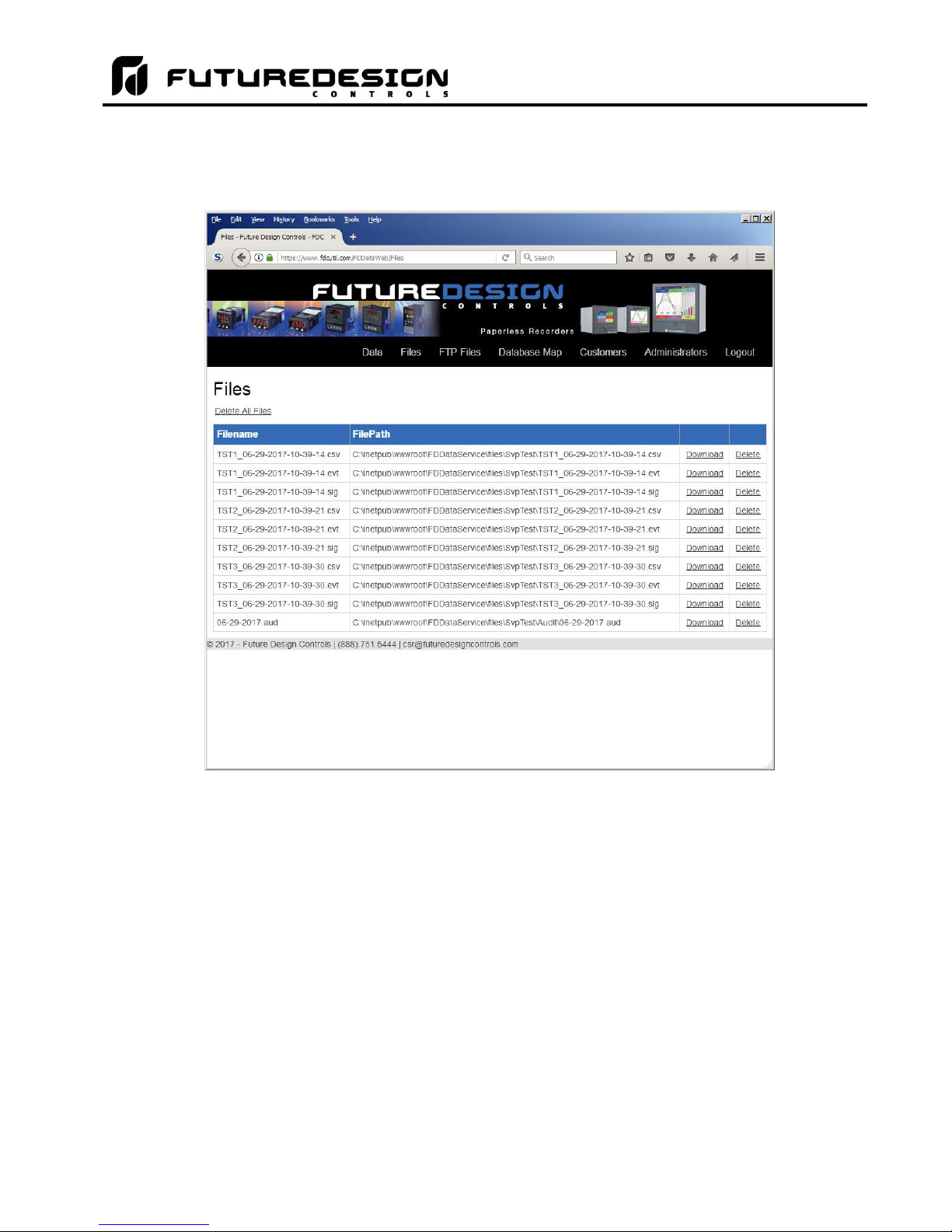
MCT-MC 4.3
Data Files Page (FileWeb):
The data files page, accessible from the “Files” menu item, lists the files in the customer’s data directory. These
are only the files in the customer’s directory, not all uploads. The user can delete the files from this page.
FileWeb sample setup using FDCutil.com:
To setup the MC for use with the FDCutil.com FileWeb server, go to the FTP/WAN screen on the MC and enter
the following data into the screen fields. Make sure to replace the “custName” and “custPassword” text below
with the actual user name/password entered during the FDCutil.com signup process.
Type = FileWeb
IP Add = https://fdcutil.com/FDDataService.svc
User = custName
Password = custPassword
Server = custName
Port = 21
Press the “Save” button to complete the setup on the MC LanWan screen. Press the “Start” button to begin a
manual transfer of files from the MC to the FDCutil.com site. Login to the FDCutil.com site to view the FTP files
by pressing on the Files link on the page (or press Files link if already logged into FDCutil.com)
FDC MCT-MC - 96 - Logging
Page 97
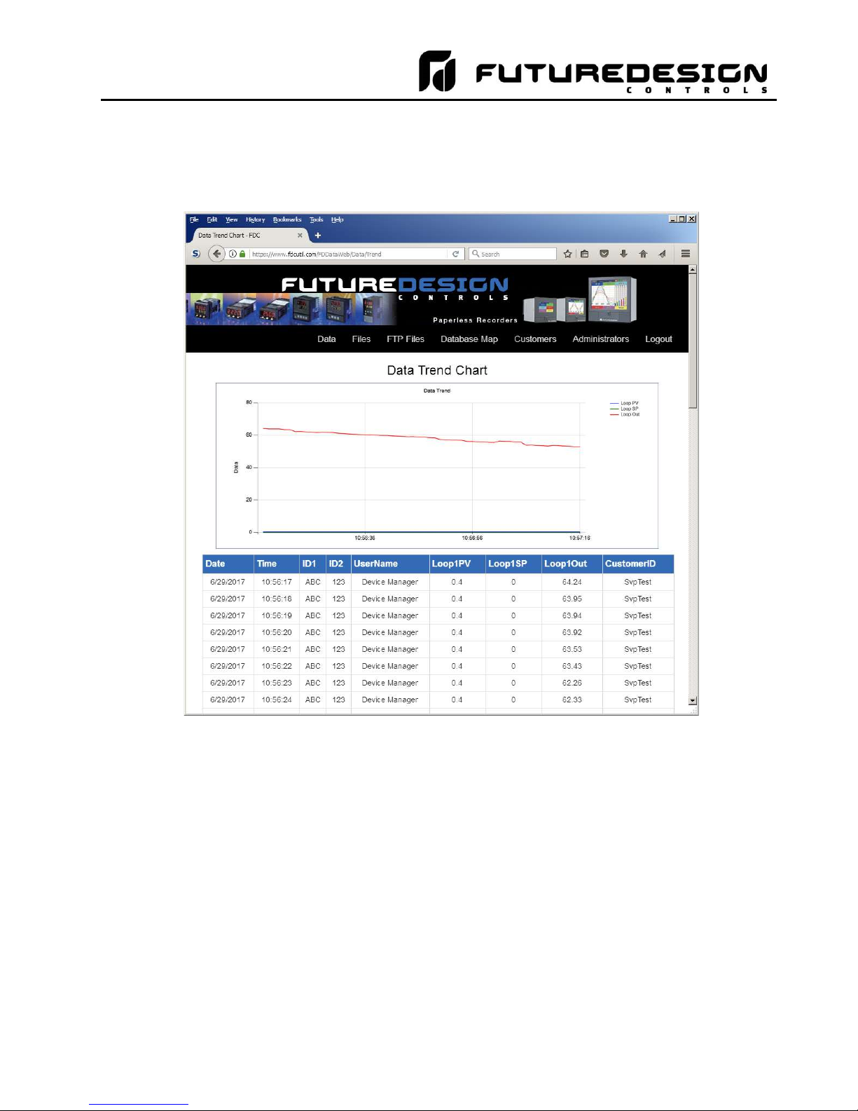
MCT-MC 4.3
Database Data Page (DataWeb):
Once logged in, the customer will be shown the database data page. If data has been uploaded to the database,
it will be displayed on this page. They can also delete data records. Choices from the Data link allows the user
to view tabular data only or tabular data with a trend of the data at the top of the page.
DataWeb sample setup using FDCutil.com:
To setup the MC for use with the FDCutil.com DataWeb server, go to the FTP/WAN screen on the MC and
enter the following data into the screen fields. Make sure to replace the “custName” and “custPassword” text
below with the actual user name/password entered during the FDCutil.com signup process.
Type = DataWeb
IP Add = https://fdcutil.com/FDDataService.svc
User = custName
Password = custPassword
Server = empty (no characters)
Port = 21
Press the “Save” button to complete the setup on the MC LanWan screen. When logging is started at the MC,
data will begin transfer to the “Data” section of the server side site. Data will be transferred to the server at the
beginning of logging (one record) with additional records transferred based on the rate that the MC data log
interval is set for.
Logging - 97 - FDC MCT-MC
Page 98

MCT-MC 4.3
If the data log interval rate is set for 60 seconds, the MC will populate the database with a single set of records
(PV, SP, %Out determined by data log/server setup) once every 60 seconds. If the data log interval rate is set
for 120 seconds, the MC will populate the database with a single set of records (PV, SP, %Out determined by
data log/server setup) once every 120 seconds. Data log intervals can be set as fast a 1 second since buffering
is used at the MC for faster data log rates, but in this case the database would receive a total of 60 records in
1 minute (one record per second). Buffering for rates faster than 1 minute is used to reduce access/overhead
at the server side while still maintaining 1 second date/time stamps for database record keeping.
NOTE: In order for the DataWeb server on the FDCutil.com website to function with your MC, the loop 1 name
of the must be programmed for “Loop1” (with capital “L” and no spaces) in the Configurator. The
FDCutil.com site is for testing only and utilizes a fixed DataWeb table for simplicity. If the loop name is
not entered properly on the MC, the DataWeb interface will not operate and the data will not appear on
the website.
If the name of the loop can not be changed, the DataWeb function can not be tested via the FDCutil.com
website.
8.7 Annotation
The Annotation screen allows the user to add messages to the running data file and view any messages
currently associated with a loaded historical data file.
When a historical data file is loaded, the Annotation screen will display any messages that were written to the
file. The date, time, user name and description of the data file annotation is shown. Note that the currently
running data log file can be opened as a historical data file, and the current annotations for the running file will
be shown.
To add an annotation to the running log file, touch the “Entry” field at the bottom of the screen and enter the
message (up to 16 characters maximum). Press the “Add” button and the message will be added to the current
log file. If the running log file was opened as the historical log file, the annotation will be shown immediately on
the screen as it is added. If logging is not currently running, the entry field will be disabled.
FDC MCT-MC - 98 - Logging
Page 99
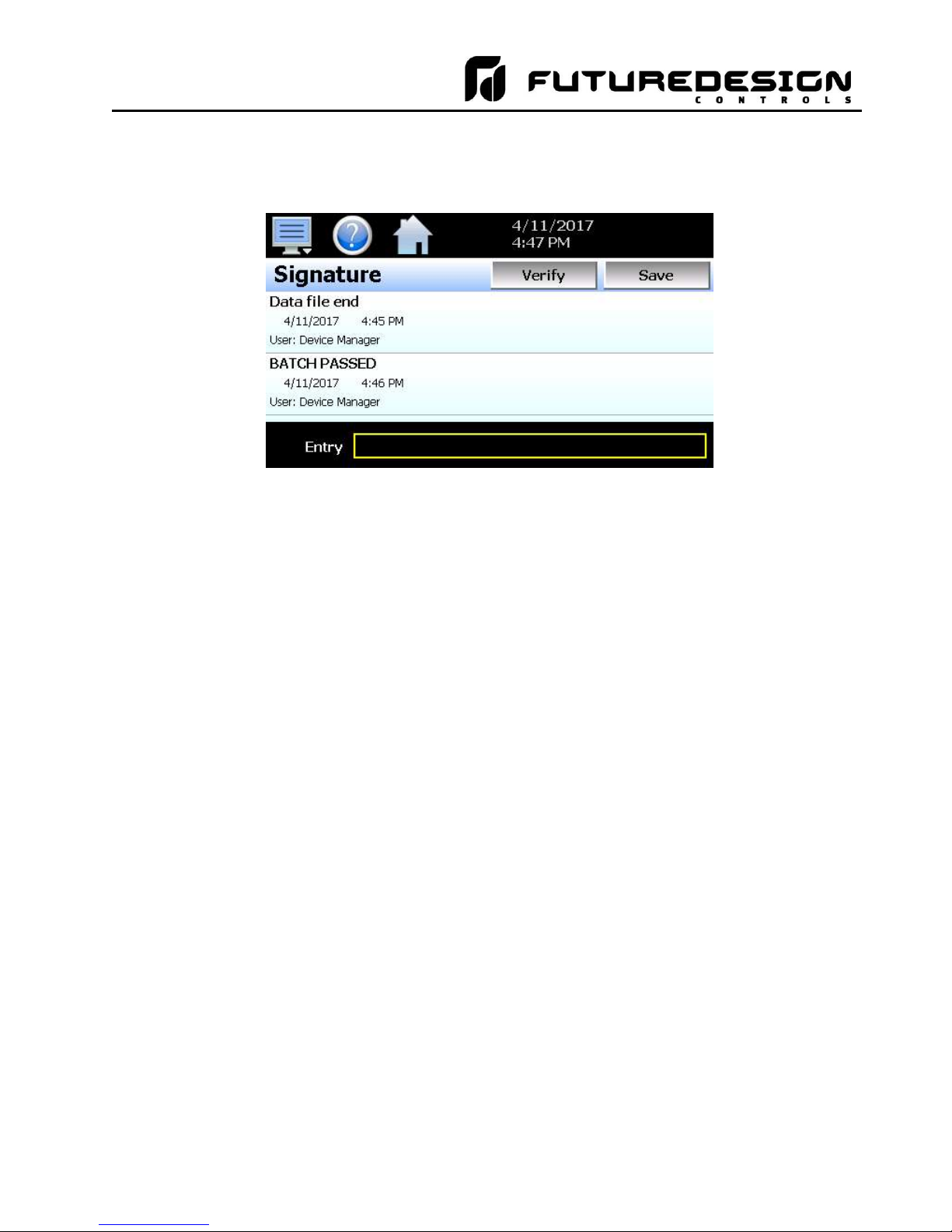
MCT-MC 4.3
8.8 Add\View Digital Signatures
The Signature screen allows the user to add digital signatures to historical data log files and view any digital
signatures currently associated with the loaded historical log file.
When a historical data file is loaded, the Signature screen will display any signatures currently associated with
the file. To verify a digital signature and insure that the data file has not been altered, touch the signature in
the list box and press the “Verify” button. The MC will compare the signature to the log file to see if any
alterations to the data have been made. The MC will then indicate if the signature is valid or not.
If the signature is valid, the historical data file is intact and has not been altered. If the signature is invalid, the
data has been altered at some time after the signature was assigned to the file. For data integrity, the MC
automatically signs a data file when logging is stopped; however, this only occurs if the “Auto Interval” is
selected on the Log screen. If a different logging interval is used, the MC will not automatically sign the file and
it must be signed by a user.
To add a digital signature to the historical log file, touch the “Entry” field at the bottom of the screen and enter
in the comment line for the signature (up to 16 characters maximum). Press the “Add” button and the signature
will be added to the log file. The signature includes the date and time of the signature, the user name and
comment line. If a user is not logged into the system, the default user name “Device Manager” will be entered
as the user.
NOTE: The Signature screen is not available if security is disabled. The MC security module must be enabled
in order to digitally sign data log files. See Section 7, Security.
Logging - 99 - FDC MCT-MC
Page 100

MCT-MC 4.3
9 Device Settings
This section covers the use of extended controller features that enhance the functionality of the system. To
gain access to the MC setup options, select “Settings” from the home Device menu.
The Device Settings menu provides navigation to the following functions:
View menu
Tuning: Provides access to manual loop tuning.
Setup menu
Alarm: Provides access to the alarm set points/message entry.
Limit: Sets minimum/maximum set points allowed for each loop.
Event: Allows the user to edit names used to describe events.
Navigation: Allows the user to choose text based or icon based/slide
page navigation menus.
Comms: Allows user to set the MC communication settings.
Email menu
Email: Provides access to the MC email system manager.
Message: Allows the user to send an email message to users
entered in the system.
Offline menu
Offline: Provides access to offline system settings.
FDC MCT-MC - 100 - Device Settings
 Loading...