

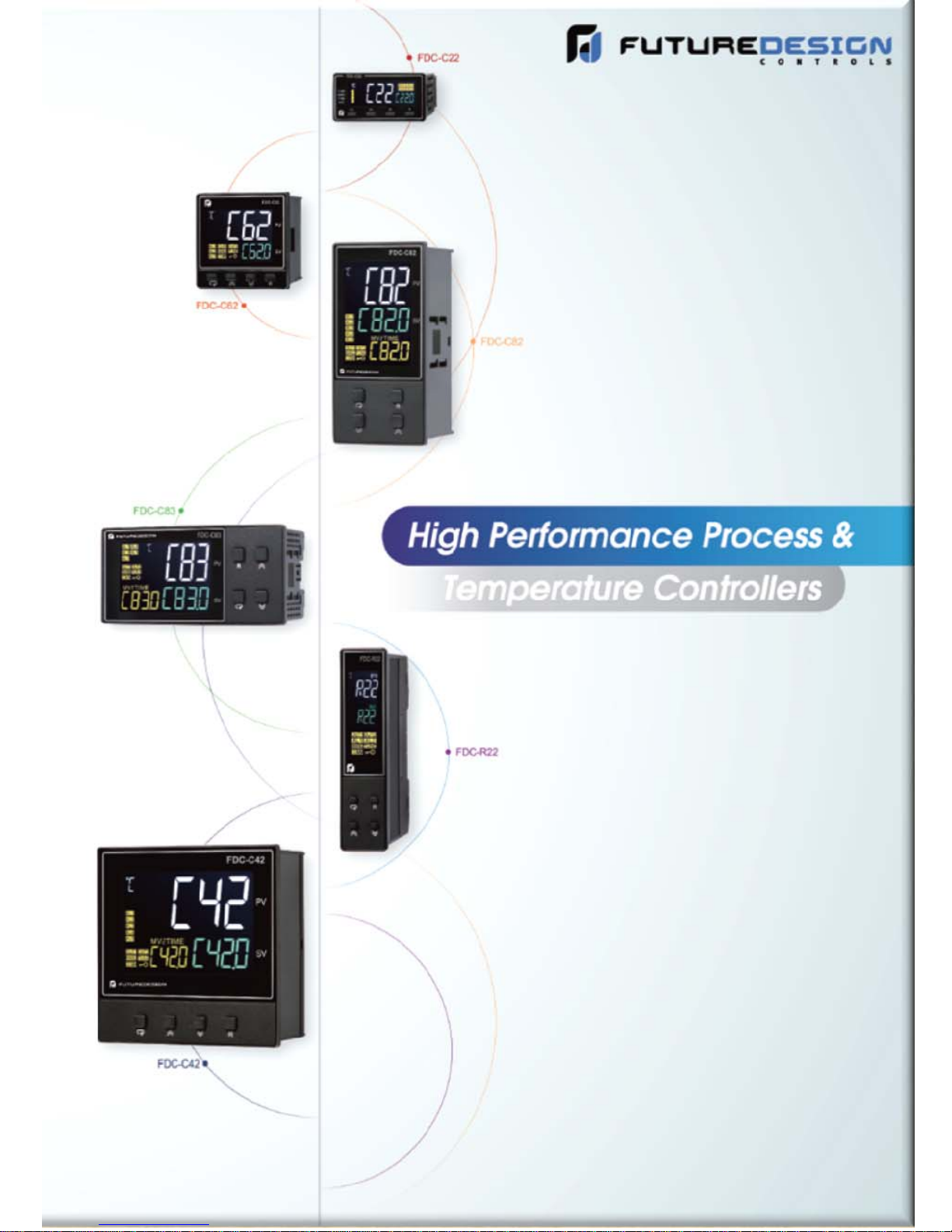
PID+ Fuzzy Logic Process Controller
C22/C62/C82/C83/C72/C42/R22
Quick Operation User Manual
FDC_C-Series_Quick_Operation_User_Manual_UMQOC621A.doc Page 1 of 20
UMQOC621A
September 2018

Quick Operation Manual C22/C62/C82/C83/C72/C42/R22
1. DISPLAY AND KEYS:
During power-up, the upper display will show PROG and the lower display will show the Firmware version for 6 seconds.
SCROLL/ENTER KEY:
Press
UP KEY:
DOWN KEY:
RESET KEY:
This key is used to increase the value of the selected parameter.
This key is used to decrease the value of the selected parameter.
This key is used to:
1. Revert the display to the home screen.
2. Reset a latching alarm once the alarm condition is removed.
3. Stop manual control mode, auto-tuning mode or calibration mode.
4. Clear an auto-tuning or communication error message.
5. Restart the dwell timer when the dwell timer has timed out.
6. Enter the manual control menu if failure mode occurs.
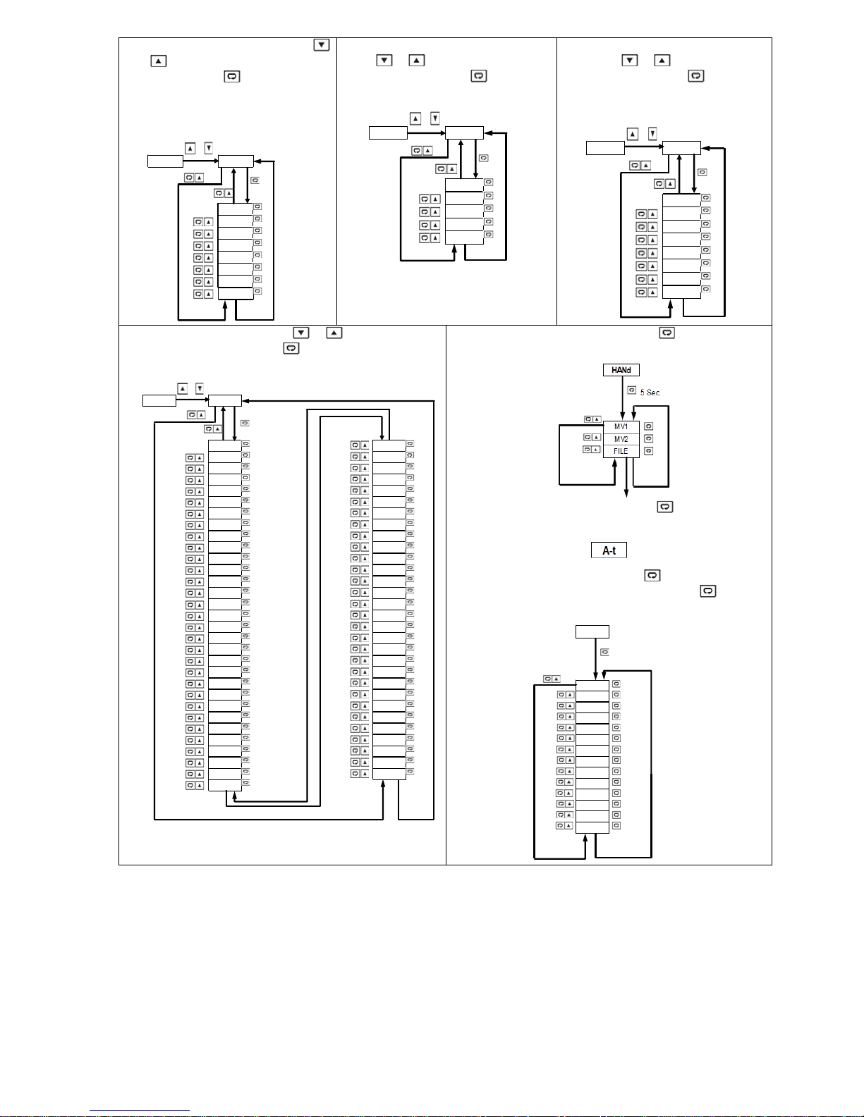
2. MENU FLOWCHART:
This key is used to select a parameter to be viewed or adjusted.
for the next parameter. Press and key for return to the previous parameter.
5 Sec 6.2 Sec 7.4 Sec 8.6 Sec 9.8 Sec
User Menu Setup Menu Manual Mode Auto-Tuning Mode Calibration Mode
SCROLL/ENTER KEY: 1. Press and hold
2. Press and hold
3. Press and hold
4. Press and hold
2.1 User Menu: The below user menu
parameters are available depends on
user’s selection.
FDC_C-Series_Quick_Operation_User_Manual_UMQOC621A.doc Page 2 of 20
for 6.2 seconds, display will show . Press and hold for 5 seconds to enter Manual Mode.
for 7.4 seconds, display will show . Press and hold for 5 seconds to enter Auto-Tuning Mode.
for 8.6 seconds, display will show . Press and hold for 2~3 seconds to enter Calibration Mode.
5 Sec 5 Sec 2~3 Sec
for 5 seconds, display will show . Press to enter the Setup Menu.
2.2 Setup Menu: The setup menu has
been categorized into eight categories
as below.
1. bASE: Basic Menu
2. oUT: Output Menu
3. ALRM: Alarm Menu
4. EI: Event Input Menu
2.2.1 Basic Menu (bASE): Use
key to get bASE in the lower
display, then use
menu parameters.
key to enter basic
or

PV,SV
SP1
SP2
SP3
SP4
SP5
SP6
SP7
SFtR
CT1R
CT2R
DTM R
PASS
RUN
CYCR
STEP
TIMR
SEL1
SEL2
SEL3
SEL4
SEL5
SEL6
SEL7
SEL8
2.2.2 Output Menu (oUT): Use or
key to get oUT in the lower display,
then use
key to enter output menu
parameters.
or
SET OUT
5. SEL: User Select Menu
6. CoMM: Communication Menu
7. Ct: Current Transformer Input Menu
8. PRoF: Profile Menu
2.2.3 Alarm Menu (ALRM): Use
key to get ALRM in the lower
display, then use
key to enter alarm
menu parameters.
or
SET ALRM
or
SET bASE
OFS1
OFS2
OFS3
INPT
UNIT
DP
INLO
INHI
SP1L
SP1H
FILT
DISP
PB
TI
TD
RAMP
RR
RETY
RELO
REHI
RMSP
RINL
RINH
CODE
OFSTL
OFSTH
CALO
CAHI
SFT
SFL1
SFL2
SFtH
or
2.2.4 Event Input Menu (EI): Use or
key to get EI in the lower display,
then use
key to enter event input
menu parameters.
or
SET EI
OUT1
O1TY
O1FT
O1HY
CYC1
OFST
OUT2
O2TY
O2FT
CYC2
CPB
DB
PL1L
PL1H
PL2L
PL2H
A1F N
A1M D
A1H Y
A1F T
A1S P
A1D V
A1D L
A2O T
A2F N
A2M D
A2H Y
A2F T
A2S P
A2D V
A2D L
A3O T
A3F N
A3M D
A3H Y
A3F T
A3S P
A3D V
A3D L
A4O T
A4F N
A4M D
A4H Y
A4F T
A4S P
A4D V
A4D L
E1FN
SP2
E2FN
SP3
E3FN
SP4
E4FN
SP5
E5FN
SP6
E6FN
SP7
FDC_C-Series_Quick_Operation_User_Manual_UMQOC621A.doc Page 3 of 20
2.2.5 User Select Menu (SEL): Use
or
key to get SEL in the lower
display, then use
key to enter user
select menu parameters. Up to 8
parameters by selecting SEL1~SEL8
can be put in the User Menu.
or
SET SEL
SEL1
SEL2
SEL3
SEL4
SEL5
SEL6
SEL7
SEL8
2.2.6 Communication Menu (CoMM):
or key to get CoMM in the
Use
lower display, then use
communication menu parameters.
or
SET CoMM
2.2.8 Profile Menu (PRoF): Use or key to get PRoF in
the lower display, then use
key to enter profile menu
parameters.
or
SET PRoF
PROF T SP7
RMPU RPT7
ST AR SKT7
END TSP8
PFR RPT 8
HBLO SKT8
HBHI TSP9
HBT RPT9
CYCL SKT9
CYCR TSPA
ST EP RPT A
TIMR SKTA
ST AT TSPB
TSP1 RPTB
RPT1 SKTB
SKT1 TSPC
TSP2 RPTC
RPT2 SKTC
SKT2 TSPD
TSP3 RPTD
RPT3 SKTD
SKT3 TSPE
TSP4 RPTE
RPT4 SKTE
SKT4 TSPF
TSP5 RPTF
RPT5 SKTF
SKT5 TSPG
TSP6 RPTG
RPT6 SKTG
SKT6
2.2.7 Current Transformer Input Menu
or key to get Ct in the
key to enter
(Ct): Use
lower display, then use
current transformer input menu
parameters.
or
SET Ct
ADDR
BAUD
DATA
PARI
ST OP
2.3 Manual Mode Menu: Press and hold
HBEN
HBHY
HB1T
HB2T
HSEN
HSHY
HS1T
HS2T
key for 5 seconds
until MANU indicator flashes to enter manual mode menu.
2.4 Auto-Tuning Mode: Press and hold
key for 5 seconds
until TUNE indicator flashes to activate auto-tuning mode.
2.5 Calibration Mode: Press and hold
key for 2~3 seconds,
release it to enter calibration mode. Then press
seconds to perform calibration.
CALI
2 sec minimum,3 sec maximum
ADLO
ADHI
RTDL
RTDH
CJLO
CJHI
V1L
V1G
MA1L
MA1G
V2L
V2G
MA2L
MA2G
key to enter
Key for 5
Note: Using Manual, Auto-Tuning, Calibration modes will break the control loop and change some of the previous setting data. Make
sure that the system is allowable to apply these modes.
FDC_C-Series_Quick_Operation_User_Manual_UMQOC621A.doc Page 4 of 20

3. PARAMETERS DESCRIPTION:
Modbus
Register
Address
0 SP1 Set Point 1 Low: SP1L High: SP1H
1 SP2 Set Point 2 Low: SP1L High: SP1H
2 SP3 Set Point 3 Low: SP1L High: SP1H
3 SP4 Set Point 4 Low: SP1L High: SP1H
4 SP5 Set Point 5 Low: SP1L High: SP1H
5 SP6 Set Point 6 Low: SP1L High: SP1H
6 SP7 Set Point 7 Low: SP1L High: SP1H
7 DTMR Dwell timer output time (Minute: Seconds) Low: 0.0 High: 4553.5
8 INPT Input sensor selection
9 UNIT Input unit selection
10 DP Decimal point selection
11 INLO Input low scale value Low: -19999 High:45536
12 INHI Input high scale value Low:INLO+50 High:45536
13 SP1L Low limit of set point value Low: -19999 High :45536
14 SP1H High limit of set point value Low: SP1L High:45536
15 FILT Filter damping time constant of PV
16 DISP MV/TIME display selection
17 PB Proportional band value Low: 0.0 High: 500.0°C (900.0°F)
18 TI Integral time value Low: 0 High: 3600 sec
19 TD Derivative time value Low: 0.0 High: 360.0 sec
Parameter
Notation
Parameter Description Range
J_tC: J type Thermocouple
K_tC: K type Thermocouple
T_tC: T type Thermocouple
E_tC: E type Thermocouple
B_tC: B type Thermocouple
R_tC: R type Thermocouple
S_tC: S type Thermocouple
N_tC: N type Thermocouple
L_tC: L type Thermocouple
U_tC: U type Thermocouple
P_tC: P type Thermocouple
C_tC: C type Thermocouple
D_tC: D type Thermocouple
Pt.dN: PT100 Ω DIN curve
Pt.JS: PT100 Ω JIS curve
4-20: 4-20mA linear current input
0-20: 0-20mA linear current input
0-5V: 0-5VDC linear voltage input
1-5V: 1-5VDC linear voltage input
0-10: 0-10VDC linear voltage input
oC: °C unit
oF: °F unit
Pu: Process unit
No.dP: No decimal point
1-dP: 1 decimal digit
2-dP: 2 decimal digit
3-dP: 3 decimal digit
0: 0 second time constant
0.2: 0.2 second time constant
0.5: 0.5 second time constant
1: 1 second time constant
2: 2 second time constant
5: 5 second time constant
10: 10 second time constant
20: 20 second time constant
30: 30 second time constant
60: 60 second time constant
None: No Display
MV1: Display MV1 (66/130)
MV2: Display MV2(67/131)
tIMR: Display Time (68)
PRoF: Display STAT(162) if have profile function
FDC_C-Series_Quick_Operation_User_Manual_UMQOC621A.doc Page 5 of 20

Modbus
(
Register
Address
20 OUT1 Output 1 function
21 O1TY Output 1 signal type
22 O1FT Output 1 failure transfer mode
23 O1HY Output 1 ON-OFF control hysteresis Low:0.1°C(0.2°F) High: 50.0°C(90.0°F)
24 CYC1 Output 1 cycle time Low: 0.1 High: 90.0 sec.
25 OFST Offset value for P control Low: 0 High: 100.0 %
26 RAMP Ramp function selection
27 RR Ramp rate Low: 0.0 High: 500.0°C(900.0°F)
28 OUT2 Output 2 function
29 O2TY Output 2 signal type
30 O2FT Output 2 failure transfer mode
31 CYC2 Output 2 cycle time Low: 0.1 High: 90.0 sec.
32 CPB Cooling proportional band value Low: 50 High: 300 %
33 DB Heating-cooling dead band (negative value= overlap)Low: - 36.0 High: 36.0 %
34 A1FN Alarm 1 function for alarm 1 output
35 A1MD Alarm 1 operation mode
36 A1HY Hysteresis control of alarm 1 Low: 0.1°C High: 50.0°C(90.0°F)
37 A1FT Alarm 1 failure transfer mode
38 A1SP Alarm 1 set point Low: -19999 High: 45536
39 A1DV Alarm 1 deviation value Low: -19999 High: 45536
40 A2OT Alarm 2 Output
Parameter
Notation
Parameter Description Range
REVR: Reverse (heating) control action
dIRt : Direct (cooling) control action
RELY: Relay output
SSrd: Solid state relay drive output
4-20: 4-20mA linear current
0-20: 0-20mA linear current
0-5V: 0-5VDClinear voltage
1-5V: 1-5VDC linear voltage
0-10: 0-10VDC linear voltage
Select BPLS
output 1 control function if the sensor fails, or select OFF (0) or
ON (1) for ON-OFF control
NoNE: No Ramp Function
MINR: Use unit/minute as Ramp Rate
HRR: Use unit/hour as Ramp Rate
NoNE:Output2 turned off
COOL: Cooling PID Function
AL1: Alarm 1 Function
rAL1:Reverse Alarm 1 Function
RELY: Relay output
SSrd: Solid state relay drive output
4-20: 4-20mA linear current
0-20: 0-20mA linear current
0-5V: 0-5VDClinear voltage
1-5V: 1-5VDC linear voltage
0-10: 0-10VDC linear voltage
Select BPLS (Bumpless transfer),or 0.0 ~ 100.0 % to continue
output 2 control function if the sensor fails
NoNE: No alarm function
dtMR: Dwell timer action
dE.HI: Deviation high alarm
dE.Lo: Deviation low alarm
db.HI: Deviation band out of band alarm
db.Lo: Deviation band in band alarm
PV.HI: Process value high alarm
PV.Lo: Process value low alarm
H.bK: Heater break alarm
H.St: Heater short alarm
NoRM: Normal alarm action
LtCH: Latching alarm action
HoLd: Hold alarm action
Lt.Ho: Latching & Hold action
SP.Ho: Set point holding alarm
OFF: Alarm output OFF if sensor fails
ON: Alarm output ON if sensor fails
ALM: Alarm 2 output 1
RALM: Reverse Alarm 2 Output
Bumpless transfer), or 0.0 ~ 100.0 % to continue
FDC_C-Series_Quick_Operation_User_Manual_UMQOC621A.doc Page 6 of 20

Modbus
A
A
E
Register
Address
41 A2FN Alarm 2 function for alarm 2 output
42 A2MD Alarm 2 operation mode
43 A2HY Hysteresis control of alarm 2 Low: 0.1°C High: 50.0°C(90.0°F)
44 A2FT Alarm 2 failure transfer mode
45 A2SP Alarm 2 set point Low: -19999 High: 45536
46 A2DV Alarm 2 deviation value Low: -19999 High: 45536
47 A3OT Alarm 3 output
48 A3FN Alarm 3 function for alarm 3 output
49 A3MD Alarm 3 operation mode
50 A3HY Hysteresis control of alarm 3 Low: 0.1°C High: 50.0°C(90.0°F)
51 A3FT Alarm 3 failure transfer mode
52 A3SP Alarm 3 set point Low: -19999 High: 45536
53 A3DV Alarm 3 deviation value Low: -19999 High: 45536
54 A4OT Alarm 4 output
55 A4FN Alarm 4 function for alarm output
Parameter
Notation
Parameter Description Range
NoNE: No alarm function
dtMR: Dwell timer action
dE.HI: Deviation high alarm
dE.Lo: Deviation low alarm
db.HI: Deviation band out of band alarm
db.Lo: Deviation band in band alarm
PV.HI: Process value high alarm
PV.Lo: Process value low alarm
H.bK: Heater break alarm
H.St: Heater short alarm
E1.C.o: Event Input 1 Control Alarm Output
E2.C.o: Event Input 2 Control Alarm Output
NoRM: Normal alarm action
LtCH: Latching alarm action
HoLd: Hold alarm action
Lt.Ho: Latching & Hold action
SP.Ho: Set point holding alarm
OFF: Alarm output OFF if sensor fails
ON: Alarm output ON if sensor fails
LM: Alarm 3 output
RALM: Reverse Alarm3 Output
NoNE: No alarm function
dtMR: Dwell timer action
dE.HI: Deviation high alarm
dE.Lo: Deviation low alarm
db.HI: Deviation band out of band alarm
db.Lo: Deviation band in band alarm
PV.HI: Process value high alarm
PV.Lo: Process value low alarm
H.bK: Heater break alarm
H.St: Heater short alarm
E1.C.o: Event Input 1 Control Alarm Output
E2.C.o: Event Input 2 Control Alarm Output
NoRM: Normal alarm action
LtCH: Latching alarm action
HoLd: Hold alarm action
Lt.Ho: Latching & Hold action
SP.Ho: Set point holding alarm
OFF: Alarm output OFF if sensor fails
ON: Alarm output ON if sensor fails
LM: Alarm 4 output
RALM: Reverse Alarm 4 Output
NoN
dtMR: Dwell timer action
dE.HI: Deviation high alarm
dE.Lo: Deviation low alarm
db.HI: Deviation band out of band alarm
db.Lo: Deviation band in band alarm
PV.HI: Process value high alarm
PV.Lo: Process value low alarm
H.bK: Heater break alarm
H.St: Heater short alarm
: No alarm function
FDC_C-Series_Quick_Operation_User_Manual_UMQOC621A.doc Page 7 of 20

Modbus
F
A
A
g)
X
A
Register
Address
56 A4MD Alarm 4 operation mode
57 A4HY Hysteresis control of alarm 4 Low: 0.1°C High: 50.0°C(90.0°F)
58 A4FT Alarm 4 failure transfer mode
59 A4SP Alarm 4 set point Low: -19999 High: 45536
60
61 BPL1 Bumpless transfer value of MV1 Low: 0.00 High: 100.00
62 BPL2 Bumpless transfer value of MV2 Low: 0.00 High: 100.00
63 CJCL Sense voltage during cold junction calibration low Low: 0 High: 7552
64 PV64 Process value Low: -19999 High:45536
65 SV65 Current set point value Low: SP1L High:SP1H
66 MV1 66 Output 1 %Value(Heatin
67 MV2 67 Output 2 %Value(Cooling) Low: 0.00 High: 100.00 %
68 TIMER Remaining time of dwell timer Low: 0.0 High: 4553.6
69 EROR Error code Low: 0 High: 65535
70 MODE Operation mode & alarm status Low: 0 High: 65535
71 PROG71 Program code
72 CMND Command code Low: 0 High: 65535
73 JOB1 Job code Low: 0 High: 65535
74 JOB2 Job code Low: 0 High: 65535
75 JOB3 Job code Low: 0 High: 65535
76 CJCT Cold Junction Temperature Low: -4000 High: 9000
77
78 ADHI mV calibration high coefficient Low: -1999 High: 1999
79 RTDL RTD calibration low coefficient Low: -1999 High: 1999
80 RTDH RTD calibration high coefficient Low: -1999 High: 1999
81 CJLO Cold junction calibration low coefficient Low: -5.00 High: 40.00
82 CJHI Cold junction calibration high coefficient Low: -1999 High: 1999
83 V1L V1 calibration low coefficient Low: -1999 High: 1999
84 V1G V1 calibration high coefficient Low: -1999 High: 1999
85 MA1L MA1 calibration low coefficient Low: -1999 High: 1999
86 MA1G MA1 calibration high coefficient Low: -1999 High: 1999
87 V2L V2 calibration low coefficient Low: -1999 High: 1999
88 V2G V2 calibration high coefficient Low: -1999 High: 1999
89 MA2L MA2 calibration low coefficient Low: -1999 High: 1999
90 MA2G MA2 calibration high coefficient Low: -1999 High: 1999
91 PL1L Power limit 1 low Low: 0 High:PL1H or 50%
92 PL1H Power limit 1 high Low: PL1L High: 100 %
93 PL2L Power limit 2 low Low: 0 High: PL2H or 50%
94 PL2H Power limit 2 high Low: PL2L High: 100 %
Parameter
Notation
4DV
DLO mV calibration low coefficient Low: -1999 High: 1999
Parameter Description Range
NoRM: Normal alarm action
LtCH: Latching alarm action
HoLd: Hold alarm action
Lt.Ho: Latching & Hold action
SP.Ho: Set point holding alarm
: Alarm output OFF if sensor fails
OF
ON: Alarm output ON if sensor fails
larm 4 deviation value Low: -19999 High: 45536
Low: 0.00 High: 100.00 %
C22:22.XX C62:62.XX C82:82.XX C83:83.X
C72:72.XX C42:42.XX R22:23.XX
FDC_C-Series_Quick_Operation_User_Manual_UMQOC621A.doc Page 8 of 20

Modbus
Register
Address
95~102 SEL1~8 Select 1st~8th parameter for user menu
103 OFS1 Option function 1 selection
Parameter
Notation
Parameter Description Range
NoNE: No Parameter selected
dtMR: DTMR is moved to USER Menu
dISP: DISP is moved to USER Menu
Pb: PB is moved to USER Menu
tI: TI is moved to USER Menu
td: TD is moved to USER Menu
o1HY: O1HY is moved to USER Menu
RR: RR is moved to USER Menu
CPb: CPB is moved to USER Menu
db: DB is moved to USER Menu
A1HY: A1HY is moved to USER Menu
A1SP: A1SP is moved to USER Menu
A1dV: A1DV is moved to USER Menu
A2HY: A2HY is moved to USER Menu
A2SP: A2SP is moved to USER Menu
A2dV: A2DV is moved to USER Menu
A3HY: A3HY is moved to USER Menu
A3SP: A3SP is moved to USER Menu
A3dV: A3DV is moved to USER Menu
A4HY: A4HY is moved to USER Menu
A4SP: A4SP is moved to USER Menu
A4dV: A4DV is moved to USER Menu
PL1L: PL1L is moved to USER Menu
PL1H: PL1H is moved to USER Menu
PL2L: PL2L is moved to USER Menu
PL2H: PL2H is moved to USER Menu
OFTL: OFTL is moved to USER Menu
OFTH: OFTH is moved to USER Menu
CALO: CALO is moved to USER Menu
CAHI: CAHI is moved to USER Menu
A1DL: A1DL is moved to USER Menu
A2DL: A2DL is moved to USER Menu
A3DL: A3DL is moved to USER Menu
A4DL: A4DL is moved to USER Menu
C82/C83/C72/C42:
NoNE: Not selected
R485: RS-485 and Remote SP
C62:
NoNE: Not selected
R485: RS-485
C22/R22:
NoNE: Not selected
R485: RS-485
EI1: Event 1 input
CT1: CT 1 input
4-20: 4-20mA retransmission output
0-20: 0-20mA retransmission output
0-5V: 0-5VDC retransmission output
1-5V: 1-5VDC retransmission output
0-10: 0-10VDC retransmission output
FDC_C-Series_Quick_Operation_User_Manual_UMQOC621A.doc Page 9 of 20

C82/C83/C72/C42:
NoNE: Not selected
CT1: CT1 input and Remote SP
CT1.2: CT1,CT2 inputs and Remote SP
C62:
NoNE: Not selected
EI1.2: Event input 1 and Event input 2
EI.CT: Event input 1 and CT2 input
CT1.2: CT1 and CT2 inputs
C22:
NoNE: No selected
4-20: 4-20mA retransmission output
0-20: 0-20mA retransmission output
104 OFS2 Option function 2 selection
105 OFS3 Option function 3 selection
106 RETY Retransmission type
107 RELO Retransmission low scale value Low: -19999 High: 45536
108 REHI Retransmission high scale value Low: -19999 High: 45536
109 ADDR Address assignment of digital communication Low: 1 High: 255
0-5V: 0-5V retransmission output
1-5V: 1-5V retransmission output
0-10: 0-10 retransmission output
AL2: Alarm 2 output
R22:
NoNE: No selected
4-20: 4-20mA retransmission output
0-20: 0-20mA retransmission output
0-5V: 0-5V retransmission output
1-5V: 1-5V retransmission output
0-10: 0-10 retransmission output
AL2: Alarm 2 output
EI2: Event2 Input
CT2: CT2 Input
C82/C83/C42:
NoNE: Not selected
4-20: 4-20mA retransmission output & Remote SP
0-20: 0-20mA retransmission output & Remote SP
0-5V: 0-5VDC retransmission output & Remote SP
1-5V: 1-5VDC retransmission output & Remote SP
0-10: 0-10VDC retransmission output & Remote SP
A.4.20: Alarm 4, 4-20mA retransmission output & Remote SP
A.0.20: Alarm 4, 0-20mA retransmission output & Remote SP
A.0.5V: Alarm 4, 0-5V retransmission output & Remote SP
A.1.5V: Alarm 4, 1-5V retransmission output & Remote SP
A.0.10: Alarm 4, 0-10V retransmission output & Remote SP
C72:
NoNE: Not selected
4-20: 4-20mA retransmission output & Remote SP
0-20: 0-20mA retransmission output & Remote SP
0-5V: 0-5VDC retransmission output & Remote SP
1-5V: 1-5VDC retransmission output & Remote SP
0-10V: 0-10VDC retransmission output & Remote SP
AL4: Alarm 4 Output
C62:
NoNE: Not selected
4-20: 4-20mA retransmission output
0-20: 0-20mA retransmission output
0-5V: 0-5VDC retransmission output
1-5V: 1-5VDC retransmission output
0-10: 0-10VDC retransmission output
AL3: Alarm 3 output
RE.PV: Retransmit process value
RE.SP: Retransmit set point value
FDC_C-Series_Quick_Operation_User_Manual_UMQOC621A.doc Page 10 of 20

2K4: 2.4 Kbits/s baud rate
g)
4K8: 4.8 Kbits/s baud rate
9K6: 9.6 Kbits/s baud rate
14K4: 14.4 Kbits/s baud rate
110 BAUD Baud rate of digital communication
111 DATA Data bit count of digital communication
112 PARI Parity bit of digital communication
113 STOP Stop bit count of digital communication
114 CT1R Reading of CT 1 Low: 0.0 High: 150.0
115 CT2R Reading of CT 2 Low: 0.0 High: 150.0
116 HBEN Enable Heater break detection oFF: Off 1 oN: On
117 HBHY Heater break hysteresis Low: 0.1 High: 50.0
118 HB1T Triple point current for heater break 1 Low: 0.0 High: 120.0
119 HB2T Triple point current for heater break 2 Low: 0.0 High: 120.0
120 HSEN Enable Heater short detection oFF: Off 1 oN: On
121 HSHY Heater short hysteresis Low: 0.1 High: 50.0
122 HS1T Triple point current for heater short 1 Low: 0.0 High: 120.0
123 HS2T Triple point current for heater short 2 Low: 0.0 High: 120.0
124 RMSP Remote SP type
125 RINL Remote SP Input low scale value Low: -19999 High:RINH-50
126 RINH Remote SP Input high scale value Low: RINL+50 High:45536
127 FILE Default File Selection
128 PV Process value Low: -19999 High: 45536
129 SV Current set point value Low: SP1L High: SP1H
130 MV1 Output 1 percentage value (Heatin
131 MV2 Output 2 percentage value (Cooling) Low: 0.00 High: 100.00
132 PASS Password entry Low: 0 High: 9999
133 CODE Security code for parameter protection
134 OFTL Offset value for low point calibration Low: -1999 High: 1999
135 OFTH Offset value for high point calibration Low: -1999 High: 1999
136 CALO Input signal value during low point calibration Low: -19999 High: CAHI-1
137 CAHI Input signal value during high point calibration Low: CALO+1 High: 45536
138~139 … Reserved …
140 PROG Program code Same as PROG71
19K2: 19.2 Kbits/s baud rate
28K8: 28.8 Kbits/s baud rate
38K4: 38.4 Kbits/s baud rate
57K6: 57.6 Kbits/s baud rate
115K: 115.2 Kbits/s baud rate
7bIt: 7 data bits
8bIt:8 data bits
EVEN: Even parity
Odd: Odd parity
NoNE: No parity bit
1bIt: One stop bit
2bIt: Two stop bits
None:No Remote SP
4-20: 4-20mA retransmission output
0-20: 0-20mA retransmission output
0-5V: 0-5VDC retransmission output
1-5V: 1-5VDC retransmission output
0-10: 0-10VDC retransmission output
dFLt: Default Menu
Ld.Us: Load User Setting
St.Us: Store User Setting
Low: 0.00 High: 100.00
Low: 0 High: 9999
0 = unprotected 1000 = user mode unprotected 9999=SPx (1
to 7) unprotected
FDC_C-Series_Quick_Operation_User_Manual_UMQOC621A.doc Page 11 of 20

NoNE: none
E
SP2: SP2 activated to replace SP1
rS.A1: Reset alarm 1 output
rS.A2: Reset alarm 2 output
rS.A3: Reset alarm 3 output
rS.A4: Reset alarm 4 output
rS.Ao: Reset all alarm outputs
141 E1FN Event input 1 function
142 E2FN Event input 2 function
143 E3FN Event input 3 function
144 E4FN Event input 4 function
145 E5FN Event input 5 function
146 E6FN Event input 6 function
147 A1DL Alarm 1 Delay (Minutes: Seconds) Low: 00.00(OFF) High:99.59
148 A2DL Alarm 2 Delay (Minutes: Seconds) Low: 00.00(OFF) High:99.59
149 A3DL Alarm 3 Delay (Minutes: Seconds) Low: 00.00(OFF) High:99.59
150 A4DL Alarm 4 Delay (Minutes: Seconds) Low: 00.00(OFF) High:99.59
151 SFT Soft Start Time (Hours: Minutes) Low: 00.00(OFF) High:99.59
152 SPL1 Soft Start Power Limit for Output 1 Low: PL1L High:PL1H
153 SPL2 Soft Start Power Limit for Output 2 Low: PL2L High:PL2H
154 SFTH Soft Start Threshold Low: -19999 High:45536
155 SFTR Soft Start Timer (Hours: Minutes) Low: 00.00 High:99.59
CA.LH: Cancel alarm latch
d.o1: Disable output 1
d.o2: Disable output 2
d.o12: Disable output 1 and 2
LoCK: Lock all parameters and Read only communication
AU.MA: Switch Auto and Manual control mode
F.tra: Failure Transfer
AL.oN: EI Control Alarm Output
SP3: SP3 activated to replace SP1
Others: Same as E1FN
: none
NoN
SP4: SP4 activated to replace SP1
rS.A1: Reset alarm 1 output
rS.A2: Reset alarm 2 output
rS.A3: Reset alarm 3 output
rS.A4: Reset alarm 4 output
rS.Ao: Reset all alarm outputs
CA.LH: Cancel alarm latch
d.o1: Disable output 1
d.o2: Disable output 2
d.o12: Disable output 1 and 2
LoCK: Lock all parameters and Read only communication
AU.MA: Switch Auto and Manual control mode
F.tra: Failure Transfer
StAR: Run profile as RUN=STAR
CoNt: Run Profile as RUN=CONT
PV: Run Profile as RUN=PV
HoLd: Run Profile as RUN=HOLD
StoP: Run Profile as RUN=STOP
SP5: SP5 activated to replace SP1
Others: Same as E3FN
NoNE: none
SP4: SP4 activated to replace SP1
rS.A1: Reset alarm 1 output
rS.A2: Reset alarm 2 output
rS.A3: Reset alarm 3 output
rS.A4: Reset alarm 4 output
rS.Ao: Reset all alarm outputs
CA.LH: Cancel alarm latch
d.o1: Disable output 1
d.o2: Disable output 2
d.o12: Disable output 1 and 2
LoCK: Lock all parameters and Read only communication
AU.MA: Switch Auto and Manual control mode
F.tra: Failure Transfer
SP7: SP7 activated to replace SP1
Others: Same as E5FN
FDC_C-Series_Quick_Operation_User_Manual_UMQOC621A.doc Page 12 of 20

161~222 For Profiler parameters description, please refer to full version user manual
4. WIRING DIAGRAM:
C22 Terminal Connection
C82/C42 Terminal Connection
C62 Terminal Connection
C83 Terminal Connection
C72 Terminal Connection
FDC_C-Series_Quick_Operation_User_Manual_UMQOC621A.doc Page 13 of 20
R22 Terminal Connection

A
A
5. PROGRAMMING:
5.1 User Security: There are two parameters PASS (password) and CODE (security code) to control the data security function.
CODE Value PASS Value
0 Any Value All parameters are changeable
1000
9999
Others
5.2 Signal Input:
INPT: Select the sensor type or signal type for signal input.
Range: (Thermocouple) J_TC, K_TC, T_TC, E_TC, B_TC, R_TC, S_TC, N_TC, L_TC,
(RTD) PT.DN, PT.JS or (Linear) 4-20, 0-20, 0-60, 0-1V, 0-5V, 1-5V, 0-10
UNIT: Select the process unit.
Range: °C, °F, PU (Process unit). If the unit is neither °C nor °F, then select PU.
DP: Select the resolution of process value.
Range: For Thermocouple and RTD Signal NO.DP, 1-DP and for Linear Signal NO.DP, 1- DP, 2-DP, 3-DP.
INLO: Select the low scale value for the linear type input.
INHI: Select the high scale value for the linear type input.
5.3 Control Output: There are 4 kinds of control modes can be configured as shown below.
Control Mode OUT 1 OUT 2 O1HY O2HY CPB DB
Heat Only REVR X ∆ X X X
Cool Only DIRT X ∆ X X X
Heat PID
Cool ON-OFF
Heat PID
Cool PID
X: Not applicable O: Adjust to meet process Requirements ∆: Required if ON-OFF Control is configured
5.4 Alarm: The controller has up to four alarm outputs depending on the controller model. There are 11 types of alarm functions and
one dwell timer that can be selected. There are 4 kinds of alarm modes (A1MD, A2MD, A3MD, and A4MD) available for each alarm
function (A1FN, A2FN, A3FN, and A4FN). In addition to the alarm output, output 2 can also be configured as an alarm. But output 2
has only provides 8 different alarm functions or dwell timer available.
5.5 Alarm Modes: There are four types of alarm modes available for each alarm function.
Normal Alarm (ALMD = NORM): When a normal alarm is selected, the alarm output is de-energized in the non-alarm condition and
energized in an alarm condition.
Latching Alarm (ALMD = LTCH): If a latching alarm is selected, once the alarm output is energized, it will remain unchanged even if
the alarm condition is cleared. The latching alarm can be reset by pressing the RESET key once the alarm condition is
removed.
Holding Alarm (ALMD = HOLD): A holding alarm prevents an alarm condition during power up. This will ignore the alarm condition
at first time after power on. Afterwards, the alarm performs the same function as normal alarm.
Latching / Holding Alarm (ALMD = LT.HO): A latching / holding alarm performs both holding and latching functions. The latching
alarm is reset when the RESET key is pressed after the alarm condition is removed.
Set Point Holding Alarm (ALMD = SP.HO): A set point holding alarm prevents an alarm from power up and / or changing set point.
The alarm output is de-energized whenever the set point is changed even if it is in an alarm condition. The alarm reverts to a
normal alarm once the alarm condition is removed.
5.6 Alarm Delay: In certain applications during startup, nuisance alarms will be generated before the process value reaches the set
point. To avoid these kinds of nuisance alarms, a time delay for alarms is available. To enable the time delay for alarms, set the
delay time using the A1DL, A2DL, A3DL, and A4DL parameters. These parameters will avoid the nuisance alarm during the process
value reaches set point.
REVR DE.HI X O X X
REVR COOL X X O O
=1000 All parameters are changeable
≠1000 Only user menu parameters changeable
=9999
≠9999 Only SP1 to SP7 are changeable
=CODE All parameters are changeable
≠CODE No parameters can be changed
ccess Rights
ll parameters are changeable
FDC_C-Series_Quick_Operation_User_Manual_UMQOC621A.doc Page 14 of 20
5.7 Ramp: The ramping function is performed during power up as well as any time the set point is changed. Choose MINR or HRR for
the RAMP setting, and the controller will perform the ramping function. The ramp rate is programmed by adjusting the RR setting.
The ramping function is disabled as soon as the Failure mode, the Manual control mode, the Auto-tuning mode or the Calibration
mode occur.
5.8 Dwell Timer: The Dwell timer can be with or without a Ramp. Alarm outputs can be configured as dwell timers by selecting dtMR
for A1FN. If A1FN is set to dtMR, Alarm 1 will act as a dwell timer. Similarly, Alarm 2, Alarm 3 and Alarm 4 will act as dwell timers if
A2FN, A3FN, or A4FN is set to dtMR. When the dwell timer is configured, the parameter DTMR is used for dwell time adjustment.
The dwell time is measured in minutes ranging from 0.0 to 4553.6 minutes. The Timer starts to count as soon as the Process Value
(PV) reaches its set point (SV), and triggers an alarm output once the time has elapsed.
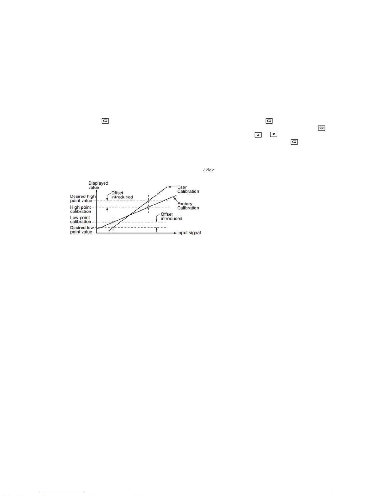
5.9 User Calibration: User calibration allows the user to offset the permanent factory calibration. There are two parameters:
Offset Low (OFTL) and Offset High (OFTH) for adjustment to correc t an erro r in the proc es s valu e.
There are two parameters for the sensor input. These two signal values are CALO and CAHI. The input signal low and high values
are to be entered in the CALO and CAHI parameters respectively.
Press and hold the
calibration low parameter OFTL. Send your low signal to the sensor input of the controller, then press and release the
the process value (the upper display) is different from the input signal, the user can use
value (the lower display) until the process value is equal to the value the user needs. Press and hold the
complete the low point calibration. A similar procedure is applied for high scale calibration.
As shown below, the two points OFTL and OFTH construct a straight line. For the purpose of accuracy, it is best to calibrate with the
two points as far apart as possible. After the user calibration is complete, the input type will be stored in the memory. If the input
type is changed, a calibration error will occur and an error code
key until the setup Menu page is obtained. Then, press and release the key to navigate to the
key. If
and keys to change the OFTL
key for 5 seconds to
is displayed.
5.10 Digital Filter: In certain applications the process value is too unstable to be read. To improve this, a programmable low pass filter
incorporated in the controller can be used. This is a first order filter with a time constant specified by the FILT parameter. A value of
0.5 seconds is used as a factory default. Adjust FILT to change the time constant from 0 to 60 seconds. 0 seconds represents no
filter applied to the input signal.
5.11 Failure Transfer: The controller will enter failure mode if one of the following conditions occurs.
1. SBER error occurs due to an input sensor break, input current below 1mA for 4-20mA or input voltage below 0.25V for 1-5V.
2. ADER error occurs due to the A-D converter of the controller fails. Output 1 and Output 2 will perform the failure transfer (O1.ft &
O2.ft) function as the controller enters failure mode.
3. Alarm Failure Transfer: An alarm failure transfer is activated as the controller enters failure mode. After that, the alarm output will
transfer to the ON or OFF state which is determined by the set value of A1FT, A2FT, A3FT, and A4FT.
5.12 Soft-Start: The controller has soft start function to limit the control output on out1 and out2 for a programmable time SFT or up to
a programmed threshold value SFTH. The first of two will terminate soft start function and the normal PID control begins. This
function is useful for effects such as suppressing the heater output during equipment startup, or lightening the load.
Note: In Profile Version controllers If PFR is set to other than SP1 then the profile function will continue with the set parameter
during power recovery. If PFR is set to SP1 then the profile will continue to run with soft start parameters during power recovery.
There are 5 parameters available for soft start function. They are as below.
1. SFt: Soft start time. If SFt ≠0, then the Soft start function will be enabled. The SFt can be set in the form of Hour: Minute. The
range can be set is 00.00 to 99:59.
2. SFL1: Soft Start output limit for output 1. It can be set from PL1L to PL1H.
3. SFL2: Soft Start output limit for output 2. It can be set from PL2L to PL2H.
4. SFtH: Soft start threshold value. The Soft start will be aborted when the process value is greater than or equal to SFtH.
5. SFtR: Soft start time. It will show the remaining time of soft start when it is running.
FDC_C-Series_Quick_Operation_User_Manual_UMQOC621A.doc Page 15 of 20
6. AUTO-TUNING: Auto-Tuning Operation Steps:
1. The system has been installed normally.
2. Don’t use zero value for PB or TI, otherwise the auto-tuning program will be disabled. The LOCK parameter should be set to NONE.
3. Set the set point to a normal operating value or a lower value if overshooting beyond the normal process value will cause damage.
4. Press and hold the
5. Press and hold the
NOTE: If the ramping function is used, it will be disabled once auto-tuning is started. The auto-tuning mode is disabled if either a failure
mode or manual control mode occurs.
Auto-Tuning Error: If auto-tuning fails, an ATER
If PB exceeds 9000 (9000 PU, 900.0°F or 500.0°C)
If TI exceeds 1000 seconds
If the set point is changed during the auto-tuning process
key until appears on the upper display, then let go.
key for at least 5 seconds. The TUNE indicator will begin to flash, and the auto-tuning process has begun.
message will appear on the upper display in any of the following cases.
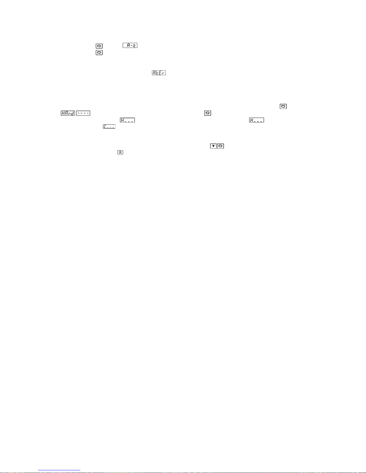
7. MANUAL CONTROL:
until
flash. The lower display will show
variable for output 1, and
percentage values for the heating or cooling output. This % value is based on the CYC1 and CYC2 settings, where the associated
output will stay on for the % of time the CYC1 & CYC2 values are set for. The controller performs open loop control as long as it stays
in manual control mode. The manual mode menu can be reached by pressing
Exit Manual Control: Press the
To enable manual control, ensure the LOCK parameter is set to NONE. Press and hold for 6.2 seconds or
(Hand Control) appears on the display. Press and hold for 5 seconds or until the MANU indicator begins to
. The controller has now entered manual control mode. Indicates the output control
indicates the control variable for output 2. The user can use the up-down keys to adjust the
keys also.
key will revert the controller to its normal display mode.
8. DATA COMMUNICATION:
RS-485 Setup: Enters the setup menu. Set individual addresses for units connected to the same port. Set the Baud Rate (BAUD), Data
Bit (DATA), Parity Bit (PARI) and Stop Bit (STOP) such that these values are accordant with PC setup conditions.
The controllers support RS-485 Modbus RTU protocol for data communication.
9. RETRANSMISSION:
retransmission option is ordered. A correct signal type should be selected for option board to meet the retransmission option installed.
RELO and REHI are adjusted to specify the low scale and high scale values of retransmission.
The controller can output (retransmit) PV or SP via its retransmission terminals RE+ and RE- provided that the
10. HEATER CURRENT MONITORING:
signal conditioner measures the heater current when the heater is powered (output 1 is on), and the current value will remain
unchanged the heater is unpowered (output 1 is off). There are 1 or 2 CT inputs that can be connected to the controllers depending on
the model. The CT1R & CT2R will indicate the heater current.
Heater break detection is enabled by enabling heater break detection setting HBEN. A Heater break alarm (H. bK) alerts the user
when the current measured by CT1 in CT1R is lower than HB1T or CT2 in CT2R is lower than HB2T. When the current measured by
CT1 in CT1R is higher than HB1T+HBHY and CT2 in CT2R is higher than HB2T+HBHY, the heater break alarm will be off. The Heater
break alarm will be off when both CT values are in normal range. The Heater break alarm function will be enabled when OUT1 is in ON
condition.
Heater short detection is enabled by enabling heater short detection setting HSEN. A Heater short alarm (H.St) alerts the user when
the current measured by CT1 in CT1R is higher than HS1T or CT2 in CT2R is higher than HS2T. When the current measured by CT1
in CT1R is lower than HS1T-HSHY and CT2 in CT2R is lower than HS2T-HSHY, the heater short alarm will be off. The Heater short
alarm will be off when both CT values are in normal range. The Heater short alarm function will be enabled when OUT1 is in OFF
condition.
A current transformer (CT98-1) is required to measure the heater current. The CT input
11. EVENT INPUT:
Refer wiring section for wiring an event input. The Event input accepts a digital (on/off) type signal. One of the available functions can
be chosen by using EIFN1 through EIFN6 contained in the setup menu. The same function cannot be set to more than one event input.
There are 6, 2 or 1 Event Inputs that are available in this series of controllers depending on the size of the controller.
12. REMOTE SET POINT:
terminals. The Remote Set point function needs RMSP, RINL, RINH parameters to be set properly.
The set point will change proportionally with respect to the input given in the Remote Set point input
13. RAMP AND SOAK PROG R AM:
automatically with the time. It provides 1 program with 16 segment or 2 programs with each 8 segments or 4 programs with each 4
segments. Each segment has both ramp and soak function. PROF, RUN, RMPU, STAR, END, PFR, HBLO, HBHI, HBT, CYC
parameters are used to configure the controller for ramp and soak programs. For more information of Profiler, please refer to full
version user manual.
The profiler option can be used in the application where the set point should be changed
FDC_C-Series_Quick_Operation_User_Manual_UMQOC621A.doc Page 16 of 20

14. ERROR CODE:
A
Error
Code
4 ER04
10 ER10 Communication error: bad function code
11 ER11 Communication error: register address out of range Do not issue an over range address of register to the slave.
14 ER14
15 ER15
16 EIER
26 ATER
29 EEPR EEPROM can't be written correctly Return to factory for repair.
30 CJER
39 SBER
40
Display
Symbol
ADER A to D converter or related component(s) malfunction Return to factory for repair.
Description & Reason Corrective Action
Illegal setup values used: COOL is used for OUT2
when DIRT (cooling action) is used for OUT1, or
when PID mode is not used for OUT1 (PB =0 and/or
TI=0)
Communication error: attempt to write a read only
data
Communication error: write a value which is out of
range to a register
Event Input Error: Two or more event inputs are set
to the same function
Auto-Tuning Error: Failed to perform auto-tuning
function
Cold junction compensation for Thermocouple
malfunction
Input sensor break, or input current below 1mA if 420mA is used, or input voltage below 0.25V if 1-5V is
used
Check and correct setup values of OUT2, PB1, PB2, TI1,
TI2 and OUT1. IF OUT2 is needed for cooling control, the
controller should use PID mode (PB≠ 0 and TI≠0) and
OUT1 should use reverse mode (heating action), otherwise,
OUT2 cannot be used for cooling control.
Correct the communication software to meet the protocol
requirements.
Do not write a read only data or a protected data to the
slave.
Do not write an over range data to the slave register.
Do not set the same function in two or more Event Input
Function parameters (E1FN through E6FN).
1. The PID values obtained after auto-tuning process are
out of range, retry auto-tuning.
2. Do not change the set point value during auto-tuning
process.
3. Use manual tuning instead of auto-tuning process.
4. Do not set a zero value for TI.
5. Do not set a zero value for PB.
6. Touch RESET key.
Return to factory for repair.
Replace input sensor.
UMQOC621A SEP 2018
FDC_C-Series_Quick_Operation_User_Manual_UMQOC621A.doc Page 17 of 20

Page Left Intentionally Blank
FDC_C-Series_Quick_Operation_User_Manual_UMQOC621A.doc Page 18 of 20

State of California Proposition 65 Warning
WARNING Cancer and Reproductive Harm: This warning is intended to address certain Prop 65
chemicals that may be found in Future Design Controls products. These products can expose you to
chemicals including lead and lead compounds which are known to the State of California to cause cancer,
birth defects or other reproductive harm.
What is the state of California Propositio n 65 ?
Proposition 65 requires businesses to provide warnings to Californians about significant exposures to chemicals that cause
cancer, birth defects or other reproductive harm. These chemicals can be in the products t hat C alifornians purchase, in their
homes or workplaces, or that are released into the environment. By requiring that this inform ati on be provided, Proposition 65
enables Californians to make informed decisions about their exposures to these chemicals. For more information go to:
www.P65Warnings.ca.gov
The most recent list of chemicals known to the State of California can be seen at:
https://oehha.ca.gov/media/downloads/proposition-65//p65list102618.pdf
Proposition 65 Warning: Affected Future Design Control Products:
This Warning applies to all existing and all future products offered by Future Design Controls.
FDC_C-Series_Quick_Operation_User_Manual_UMQOC621A.doc Page 19 of 20

Warranty
Future Design Controls C-Series products are warranted to be free from functional defects in materials and
workmanship at the time the products leave Future Design Controls facilities and to conform at that time to the
specifications set forth in the relevant Future Design Controls manual, sheet or sheets for a period of three years
after delivery to the first purchaser for use.
There are no expressed or implied Warranties extending beyond the Warranties herein and above set forth.
Limitations
Future Design Controls provides no warranty or representations of any sort regarding the fitness of use or
application of its products by the purchaser. Users are responsible for the selection, suitability of the products for
their application or use of Future Design Controls products.
Future Design Controls shall not be liable for any damages or losses, whether direct, indirect, incidental, special,
consequential or any other damages, costs or expenses excepting only the cost or expense of repair or
replacement of Future Design Control products as described below.
Future Design Controls sole responsibility under the warranty, at Future Design Controls option, is limited to
replacement or repair, free of charge, or refund of purchase price within the warranty period specified. This
warranty does not apply to damage resulting from transportation, alteration, misuse or abuse.
Future Design Controls reserves the right to make changes without notification to purchaser to materials or
processing that do not affect compliance with any applicable specifications.
Return Material Authorization
Contact Future Design Controls for Return Material Authorization number prior to returning any product to our
facility.
Future Design Controls, Inc.
7524 West 98th Place
Bridgeview, IL 60455
www.futuredesigncontrols.com
Main Office Phone: 888-751-5444
Fax: 888-307-8014
email: csr@futuredesigncontrols.com
Technical Support
Phone: 866-342-5332
Email: support@futuredesigcontrols.com
FDC_C-Series_Quick_Operation_User_Manual_UMQOC621A.doc Page 20 of 20
 Loading...