

Page 1

1 | P a g e
User Guide
For the FutureCow ChemMix XV
Includes Product Manual and Troubleshooting Guide
Date: 9/19/16
The Gold Standard in Teat Prep
Page 2
2 | P a g e
1 INTRODUCTION
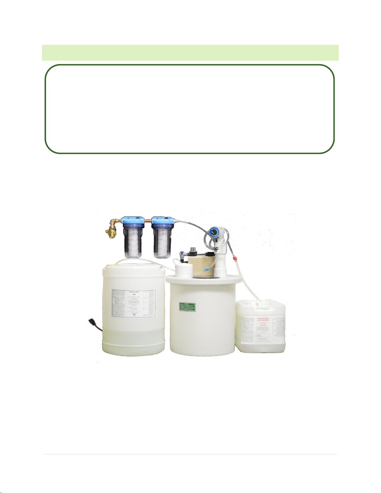
The ChemMix XV system is a simple and convenient way to achieve the required activation for chlorine
dioxide based products. The ChemMix XV is designed to automatically prepare an activated solution at a
desired concentration.
The ChemMix XV is manufactured to work with your FutureCow Teatscrubber System. The purpose is to
eliminate the need to hand measure, manual mix, or dilute your product. This system ensures precise and
consistent activation to your desired ppm.
This manual will walk you through replacement parts, troubleshooting, as well as, the testing of the product
for accurate product mixing.
Should any technical questions arise please call for a FutureCow Technician at 855.388.7269.
Please read the entire instruction manual and all associated technical
literature before beginning the setup and operation process.
Your safety, and the safety of others, is very important. To help, we have
provided setup, operating instructions and other information in this manual.
Please follow these instructions for any maintenance or troubleshooting
necessary. When handling chemical please take the recommended
precautions specified, ie: gloves and safety goggles.
Page 3
3 | P a g e
2 PARTS LIST / PART LOCATOR
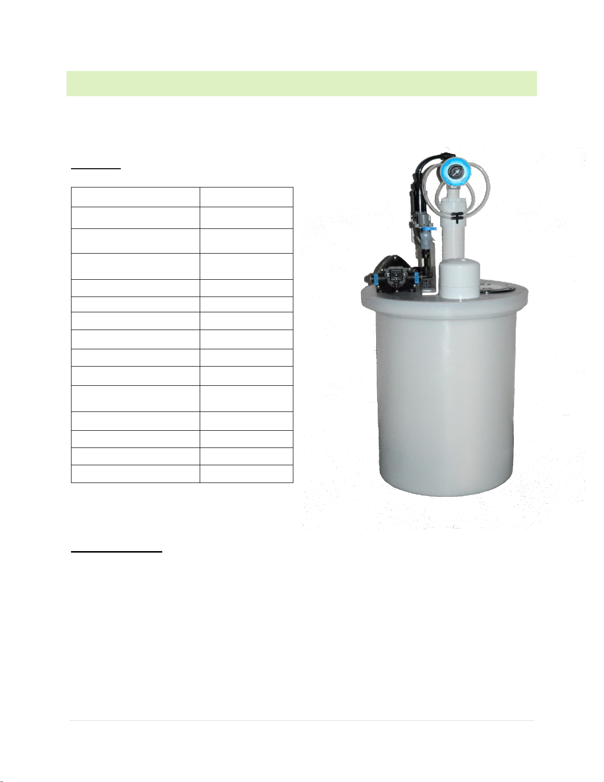
Parts List
Dealer Only Parts
Chlorine Dioxide Test Kit
Multi PPM Dial
Demand Pump 115v
AANE-PMP115V
Metering Tip
E-NIPPLE
Adapter, ¼” MNPT x
3
/
8
”
PTC
CMM3/8PTCX1/4NPT
Demand Pump Fittings 3/
8
PTC
AANE-HB3/8
3
/8” THV Tubing
E-3/8THVTUBE
Intake Hose Assem
E-AANEINTAKE
Acid Check Valve
E-VALVESRED
Product Check Valve
E-VALVESBLUE
Acid Foot Valve
E-ACFTVALVE
Product Foot Valve
E-PRFTVALVE
Ceramic Weight, For Foot
Valve
E-C346
Orifice Pack
E-ORIMTRSET
Power Cord
E-POWCHD
Venturi Tower
E-VENTOW-LOW
Fill Foat Valve
E-VALVESFLT
Page 4

4 | P a g e
3 REQUIREMENTS
Water Supply
A back flow preventer is required in the water supply line. A water filter assembly with back flow preventer
is provided. Consult local inspector to insure minimum back flow protection is maintained.
Range 25 to 80 psi, 1.6 to 5.5 bar, a pressure booster pump is required if water pressure drops below 25 psi
at any time during operation.
1.3gpm, 4.5 liters per minute is the minimum water flow for proper activation.
33° to 100°F, 1° to 38°C is the operating range required.
Location and Chemicals
Place the unit and supply drums out of direct sunlight and accessible for chemical replenishment. We
recommend a dry room located close to the FutureCow ChemMix XV. DO NOT place the ChemMix XV
in the elements. Keep equipment and solution under cover at all times. DO NOT cross contaminate, this
will lead to inaccurate readings. When changing out the solution barrels always use proper eye and skin
protection. Gloves and goggles should be worn when handling the solution. See SDS for proper protection
guidelines.
Warning:
This unit has been approved for use with FutureCow solution and FutureCow parts ONLY. Use of
any other chemical products or replacement parts voids the warranties, and negates any
responsibility FutureCow may assume with regard to product support.
Consult FutureCow product SDS for safety instructions and safety equipment requirements.
The activator is an acid product. Consult the product SDS for safety instructions and safety
equipment requirements.
Page 5
5 | P a g e
4 SETUP
The ChemMix XV is shipped dialed to the correct chemical settings, you must turn on the valve with the
desired ppm after full set up is complete to get chemical flow. The preset ppm is 400, 600, 800 or 1000.
Based on the facility needs the dairy can open the valves necessary to achieve their desired ppm
requirements.
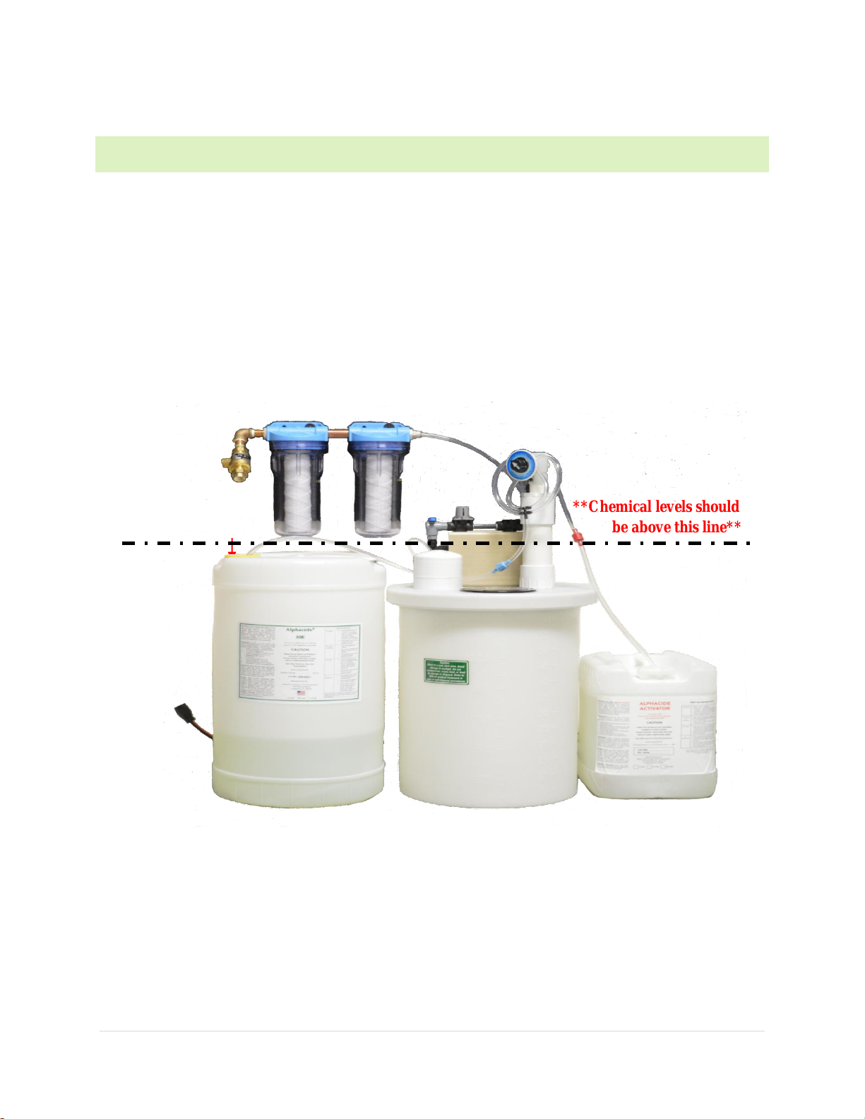
The location for the ChemMix XV should be one that is out of the elements and accessible to replace the
chemical when necessary. The chemical levels in the supply drums must never be higher than the venturi
intake points. If the supply drums are elevated by a secondary containment system, the unit must be raised
to an equal height or placed on a secondary containment system as well. This will prevent siphoning of
chemicals into the solution tank.
Connecting the unit to a water supply
is accomplished by attaching the supplied
water filter assembly to the
water inlet
and attaching to a potable water source. The unit must be installed in compliance with all local
plumbing codes.
Care must be taken during the installation process to
keep pipe and thread sealing
preparations
to a minimum. Introduction of foreign
materials into
the unit can cause a malfunction of the
valves and venturi.
**Chemical levels should never
be above this line**
Page 6

6 | P a g e
Next attach the floats. Before this step can be accomplished an estimate of the activated solution the unit
will need to produce per hour must be determined. This unique system will produce up to 24 times the
solution tank’s maximum volume per day. The 15-gallon unit holds 11 gallons of activated solution. Attach
and hang the fill-float directly on the fill-float actuator cable.
Each float can be attached by sliding the hook end of its cable into the well of the float, rotating the float
until the cross bar of the float is perpendicular to the hook of the cable and then lifting the hook on to the
cross bar. If it has been determined the extension wire is unnecessary, hang the fill-float directly on the fillfloat actuator cable.
If the float extension wire is necessary, bend the extension wire at the desired length, attach the fill-float to
the hook end, and attach the bent end to the fill-float actuator cable (see picture below). In either case hang
the safety-float directly on the safety-float actuator cable. Observe the floats to make sure they are properly
connected. Gently lift the fill-float actuator cable to assure the fill-float moves freely. When the cable is
lifted the fill-valve should click off. Once the cable is released it should click back on. Follow the same
procedure for proper connection of the safety-float.
The unit should appear as one of the two
pictured to the right. Which one depends
on whether or not the extension-wire was
used. Notice the difference in solution
levels that must be reached before the fillfloat will shut off the fill-valve and stop
filling each unit.
In either case, the unit will automatically
refill the solution tank to the preset level
with fresh active solution as needed.
Page 7

7 | P a g e
The final step in setting up the un
it is to attach each chemical intake tube to its respective
intake point. Each
intake
point is marked at the top of the venturi intake assembly. Connect
each intake tube by gently
sliding
its open end into the designated area. The blue product tube will go into the PTC marked Alphacide 30K and
the red acid tube will go on the venturi marked Activator.
Make sure the ceramic weight
is at the bottom end
of each intake tube next to its foot valve
and place the intake tube
s into the bottom of their respective supply
drums. The hose should always be cut to length to eliminate any loops and insure proper flow of chemical.
Picture above is the Alphacide 30K (product) check valve, intake hose, and weighted foot valve and the
Activator (acid) check valve, intake hose, and weighted foot valve. The weight goes into the product and
the check valve should be closest to the ChemMixXV hook up. The product (Alphacide 30K) will always
be the blue hose and the acid (Activator) will always be the red hose.
These should never be switched for any reason.
Page 8

8 | P a g e
5 TESTING THE UNIT
At this point, the unit should be properly
assembled, positioned, connected to a water
supply, and its intake
tube
s placed in their respective supply drums. Turn the blue water inlet valve to “on”. Water should begin
to flow through the system and
into the solution tank. Check the
function of the fill-valve and the safety-
valve by gently
lifting each actuator cable one at
a time. When each actuator cable is lifted, its valve
should
stop the water flow. After
releasing the
cable, water should again flow. Within
seconds, the product intake
tube
will fill with product. The activator intake tube will take
longer to fill, approximately 15-30
seconds.
As the water flows, check the chemical intake
tubes for suction. After verification
of suction, the unit is
now functioning properly and
ready for sampling. Set the ppm dial to desired concertation.
Wait one to two minutes after flow
has been established through the unit and into
the solution tank. Sample
the solution
with a plastic cup as it enters the solution tank.
To do this, simply remove
the 4" access port
plug on the top of the lid. Slide the cup
through the access port and
under the solution outlet inside the
solution tank. Collect
approximately 6 ounces of sample
and turn the control valve to the "off" position.
Set
the sample aside for approximately
5 minutes. Observe the sample. It should have a
slight yellow color
present. If the
color is present, activation is occurring and the factory
product parameters are adequate.
Check
the pH of the sample. The sample should
have a pH range of 2.0 to 3.0 or
as specified by application.
After verification, slowly
turn the control valve back to the
"on" position and continue filling the solution
tank.
The system will continue
to fill until water flow is stopped by the fill-valve at the pre-set
level
determined by the fil
l-float. During initial setup, after the unit has filled for the first
time, wait one hour
before using the activated
solution.
The unit is equipped with a solution
well designed for drawing active solution from the
bottom of the
solution tank. Simply
drop metering equipment tube(s) through the predrilled
holes in the solution well
access
cap. Additional holes or larger holes can be bored in the
cap if needed. Consult metering equipment
instruction
manuals for installation requirements.
Page 9

9 | P a g e
6 CHOOSING METERING TIPS
Over time, the Chem Mix XV will need to be recalibrated to mix the correct ppm. When it is time to do
this, you simply will need to test the solution and change the orifice on the valves accordingly. When
starting maintenance on the valves, always start will the lowest concentration first and work your way up
to the highest. This will eliminate any false readings.
You will need:
1- Orifice Pack
1- Needle Nose Pliers
1- Chlorine Dioxide Test Kit
All of these can be ordered through FutureCow or your FutureCow Dealer. All parts are shown on your
Parts List in the User Manual. If any questions arise please seek a FutureCow Technician.
To start you will need to test the chemical ppm levels, first start with the lowest ppm valve. Run the chemical
with only that valve on, take a sample of the mixed product. Use your Chlorine Dioxide Test Kit to test the
ppm. If it reads correctly move on to the next higher valve. If it does not read correctly, you will have to
change that orifice.
In order to change an orifice, first turn the valve to off, then remove the manifold to expose the metering
tip where the orifice is located. The orifice will be the small colored piece sticking out of the metering tip.
Take needle nose pliers and unscrew the orifice.
The orifice tip needed to achieve the designated ppm might not always be the same color as the one
previously in place, however, a good place to start would be by replacing the orifice with the same color as
previously used.
Place the manifold back over the new orifice and metering tip, turn the valve to on and take another sample
of the finished solution. If the reading is the desired ppm move on to the next valve until you have finished
all of the recalibrations.
If the reading is not accurate, follow the sizing chart located in the orifice pack bag for the next larger or
smaller orifice depending on how the solution read until you achieve the correct ppm.
Page 10

10 | P a g e
7 PROBLEMS AND SOLUT IONS
This unit has been tested and approved for use with the FutureCow Teatscrubber System and FutureCow
approved products only. Use of any other chemical or products voids all warranties, and negates any
responsibility FutureCow may assume with regard to product support.
Consult the appropriate product SDS for safety instructions and safety equipment requirements.
The activator is an acidic product. Consult the product SDS for safety instructions and safety equipment
requirements.
Water will not flow through the system
With the control valve in the "on"
position, lift up and then pull down on the two
actuator cables attached
to
the fill and safety valves at the same time. Water should
pass through the unit and into t
he solution tank. If
this does not happen, follow the
steps below until
problem is
resolved.
1. Check the water source for
proper pressure and volume.
2. Make sure the control valve is
in the "on" position. When the blue handle is pointed
toward the safety
valve and parallel
to the support structure it is on.
3. Check to see if the solution tank
is full. Normal operating tank volume is 1/2 to 2/3 full,
less, if the float
extension wire
is installed.
4. Make sure the fill-float actuator cable
and the safety-float actuator cable are connected
to their respective valves. Each cable should
be hooked around the bail wire of its valve.
5. Observe the floats to make sure
they are properly connected. Check the function of th
e
fill-valve and
the safety-valve
by gently lifting each actuator cable one at a time. When
each actuator cable is lifted; the valve
should stop the water flow. After releasing the
cable, water should again flow.
6. Remove the filter cartridge and check
for clogging. Clean if necessary.
If the above steps do not facilitate
water flow through the unit, one or both of the valves
may need to be
cleaned or replaced
.
Page 11

11 | P a g e
No suction in chemical
intake tubes
As water flows through the unit, the
chemical intake tubes should begin to fill. The
product intake tube
should fill within
seconds. The activator intake tube will take longer
to fill, approximately 15-30 seconds
.
Verify suction by lifting each intake tube one at a
time from its supply drum, it should
begin to suction in
air, creating small air bubbles in
the intake tube. If this does not happen, follow
the steps below until the
problem is resolved.
1. Check the product levels in the
chemical supply drums.
2. Make sure the orifice tip at each intake
point is not clogged or crystallized.
3. Make sure each foot valve, inline check valve
, and intake tube is not clogged or damaged.
4. Check to see that water supply line meets p
si and flow requirements.
If the above steps do not facilitate
suction through the intake tubes, one or both sides of
the venturi intake
assembly
may need to be repaired or replaced.
No yellow color present
If the directions for setting up the
unit have been followed, but the product shows no sign
of activation within
5 minutes
, follow the steps below until the problem is resolved.
1. Verify suction in the product in
take tube and the activator intake tube.
Read "No suction in chemical
intake
tubes" for help verifying suction and the
steps to be taken for correcting.
2. Check the pH of the sample
. Make sure the pH of the solution is within the range of
2.0 to 3.0 or as
specified by application
. To do this, simply remove the 4" access port
plug on the top of the lid. Slid
e a
plastic cup through the access port and under the
solution outlet inside the solution tan
k. Collect
approximately 6 ounces of sample and
turn the control valve to the "off" position, then
check the pH. Set
the sample aside for
about 5 minutes. Observe the sample. The
solution should have a slight yellow color
present.
If the color is present, activation
is occurring and the factory product parameters are adequate
.
If the pH of
the solution is
out of range, read "Changing pH of activated solution" to correct.
Changing the pH of the
activated solution
Before making any changes to the
pH or concentration, check the QC sheets that accompany
this manual
for the factory preset
pH and concentration levels of this unit. Note the color o
f the
orifice to be changed.
Make no more
than one orifice size changes up or down between
adjustments (see
color orifice
chart
in
orifice pack).
The Alpha is a venturi based system
that draws chemicals through orifices to control pH
and
concentration
(ppm). Therefore,
when a change of orifice is made on one side of the vent
uri
assembly,
the
other side is
slightly
affected as well. For example, if a change is made to a
larger
size orifice in the activator side of
the
Page 12

12 | P a g e
venturi assembly, the pH will drop and the concentration will lower
. This occurs because
the venturi
assembly is now pulling more on
the
activator intake and compensating
by pulling less on the product intake.
In contrast, a change
to a smaller orifice will cause the
pH to go higher, and the concentration to increase.
If the solution pH is higher than 3.0
, follow the steps below to lower the pH.
**Never operate without both product
and activator orifices in place. **
1. Turn control valve to the
off position.
2. Carefully remove the activator intake hose from
its intake point.
3. Unscrew the exposed orifice tip.
4. Replace the orifice with the next
larger size according to the chart insert in the
orifice pack, (more
activator lowers
the pH). Be careful not to over
tighten.
5. Reinstall the activator intake hose.
6. Restart water flow, verify suction, and check
the pH of the solution.
If the solution is higher than 3.0,
repeat steps 1 through 5 until the desired pH is
reached.
If the solution pH is lower than 2.
0, follow the steps below to raise the pH.
**Never operate without both product
and activator orifices in place. **
1. Turn the water valve to
the off position.
2. Carefully remove the activator intake hose from
its intake point.
3. Unscrew the exposed orifice tip.
4. Replace the orifice with the next
smaller size according to the chart insert in the
orifice pack, (less
activator raises
the pH). Be careful not to over tighten.
5. Reinstall the activator intake hose.
6. Restart water flow, verify suction, and check
the pH of the solution.
If the solution is lower than 2.0, repeat
steps 1 through 5 until the desired pH is reached.
Page 13

13 | P a g e
8 MAINTENANCE
Please read the entire instruction manual before performing any of the maintenance tasks listed below.
Information on how to accomplish these tasks as well as important safety information can be found in
previous sections within this manual.
Follow this chart to maintain performance and extend the life of the unit:
FutureCow additional technical information and can answer questions about the proper maintenance
and/or replacement parts for this unit.
Contact FutureCow for any additional information or assistance not contained in this manual.
Page 14

14 | P a g e
CHEM MIX XV QUALITY AND PERFORMANCE CHECK LIST
PHYSICAL CHECK LIST-WATER OFF
Each test must pass before proceeding.
Check to see that the unit is configured to the specifications order sheet.
Check to see that all plumbing is correct according to assembly drawing.
Check for physical flaws. (Dents, scratches, cracks, improper holes)
WET CHECK LIST-HIGH PRESSURE
Attach the unit to a pressure system capable of 75psi.
Incresase the pressure to 75psi. Allow unit to pressurize for at least 15 minutes. Engage both float
valves by lowering the bail of each. This action will allow water to flow through the unit. Allow
water to flow through the unit for 1 minute and release the bail of each float valve. Check for
leaks.
WET CHECK LIST-WORKING PRESSURE
Place the Fill Float and Safety Float in a bucket of water to check buoyancy. The tops of both
floats should float approximately 1” above surface of the water. Set Pressure system to 50psi,
unless an otherwise specific pressure is listed on the order sheet. Connect floats to the unit and
check for binding by raising and lowering each float in turn. Check for flow of water through the
venture when the floats are down and the float valves snap open. Check for no flow of water
when the floats are up and the float valves snap shut. Both floats and valves should perform the
same.
CHEMICAL INJECTION CHECK LIST
Chemicals listed here must match specifications listed on order sheet.
Precursor ____________________ Precursor Orifice Color _____________________
Activator _____________________ Activator Orifice Color _____________________
LABORATORY CHECK LIST
Water Pressure during check _______ psi
The pH of the solution from the venturi ______ pH
The available ClO2 concentration of the solution ______________________________ ppm w/w
Lab Tech Signature ____________________________________ Date _________________
Q.C. Signature ________________________________________ Date _________________
Unit Serial Number ________________
 Loading...