


Title Page
M
Spectrum Series™
Base Loaded Mobile Antennas
Installation Manual
Motorola Inc.
1301 E. Algonquin Rd.,
Schaumburg, IL 60196-1078, U.S.A.
6880309C12-F

Foreword
This manual applies to mobile radios, unless otherwise specified. It includes instructions for installing antennas in a vehicle
roof-top configuration.
Product Safety and RF Exposure Compliance
Before using this product, read the operating instructions
for safe usage contained in the Product Safety and RF
C a u t i o n
This radio is restricted to occupational use only to satisfy FCC RF energy exposure requirements.
Before using this product, read the RF energy awareness information and operating instructions in the
Product Safety and RF Exposure booklet enclosed with your radio (Motorola Publication part number
6881095C99) to ensure compliance with RF energy exposure limits.
For a list of Motorola-approved antennas, batteries, and other accessories, visit the following website: http://www.motorola.com/governmentandenterprise
Document Copyrights
No duplication or distribution of this document or any portion thereof shall take place without the express written permission
of Motorola. No part of this manual may be reproduced, distributed, or transmitted in any form or by any means, electronic
or mechanical, for any purpose without the express written permission of Motorola.
Exposure booklet enclosed with your radio.
ATTENTION!
Disclaimer
The information in this document is carefully examined, and is believed to be entirely reliable. However, no responsibility is
assumed for inaccuracies. Furthermore, Motorola reserves the right to make changes to any products herein to improve
readability, function, or design. Motorola does not assume any liability arising out of the applications or use of any product
or circuit described herein; nor does it cover any license under its patent rights nor the rights of others.
Trademarks
MOTOROLA, the Stylized M logo, and ASTRO are registered in the US Patent & Trademark Office. All other products or
service names are the property of their respective owners.
© 2000 – 2010 by Motorola, Inc.
Spectrum™ Series Base Loaded Mobile Antennas
Manufactured by Motorola
• Antenna Installation
• Mounting Instructions
• Cutting Charts
• Replacement Parts
• Connector Instructions
Important
Introduction
Thank you for selecting the Spectrum mobile antenna. The Spectrum antennas have been designed
to withstand demanding and rugged environments. During the design phase, the antennas are put
through extensive Accelerated Life Testing (ALT), which simulates years of in-field service. As a
result, potential problems are designed out, helping to ensure that the antennas which you receive
can give you years of dependable performance.
Important
Motorola Communications Part Division
1313 E. Algonquin Road
Schaumburg, Illinois 60196
To order, Call Toll-Free: 1 - 800- 422 - 4210
DANGER
Read all instructions carefully before starting the installation.
Antenna contact with high voltage wires may result in death
from electrocution.
Since April 3, 1994, the warranty on Spectrum antennas have been
changed to one year. Motorola manufactured Spectrum antennas are
warranted to be free from defects in workmanship and materials for a
period of (1) one year from the date of shipment.
Before You Start
Roof Mount Safety Precautions and Problem Prevention – for Motor Vehicle Use only
Safe Antenna Installation
Be sure to mount the antenna on a horizontal surface to keep
the antenna as vertical as possible, thus preventing the
C a u t i o n
antenna from protuding beyond the vehicle and causing
bodily injury and/or property damage.
2 Introduction
Entering Garages
Remove the antenna from the vehicle when entering a garage
to prevent damage to the vehicle and the antenna whip/ball
C a u t i o n
from damaging overhead light fixtures and garage doors.
Automatic Car Wash
Remove the entire antenna from the vehicle before entering
the automatic car wash to prevent damage to the antenna and
vehicle. The antenna mount contact must be wiped dry to
C a u t i o n
prevent moisture from damaging the contact.
Installation
Where to Mount the Antenna
General
Motorola recommends that mobile antennas be located as follows:
Recommended Antenna Location
Standard Metal Passenger vehicles Recommended Location
Standard metal passenger vehicles Center roof or center trunk lid
Vans, pickups, and other light trucks
(metal roofs)
Heavy duty equipment with metal roofs
(heavy duty trucks, semi-tractors, heavy
refuse trucks, cement mixer trucks)
Specialty vehicles (such as T-roofs, sun
roofs, or convertibles)
Other vehicles Contact your Motorola Field Technical
Center roof
Center cab roof
Center trunk lid–recommended only for transmitter
output of less than 7 W.
Representative.
Select a location for the antenna as near the center of the roof as possible. Probe the headlining with
your fingers to make sure that all points of obstruction are avoided.
Mobile Antenna Installation 3
Mobile Antenna Installation
Mobile Radio Operation and EME Exposure
Observe the following caution and electromagnetic energy exposure (EME) statements when
installing antennas:
Use caution when installing antennas with mobile radio
equipment using transmitter powers in excess of 7 W.
C a u t i o n
NOTE: For low power mobile radios (7 W or less), there are no antenna type or installation
restrictions.
To assure optimal radio performance and that human exposure to radio frequency electromagnetic
energy is within the guidelines references in this document, transmit only when people outside the
vehicle are at least the minimum distance away from a properly installed, external mounted antenna.
Table 1 lists the minimum distance from several different ranges of rated radio power.
Rated Power of Vehicle-installed
Mobile Two-Way Radios
7 to 15 Watts 1 foot (30.5 cm)
16 to 50 Watts 2 feet (61 cm)
More than 50 Watts 3 feet (91.5 cm)
Selecting an Antenna Site
1. Install the vehicle antenna external to the vehicle and in accordance with the requirements of
this documents.
2. The best mounting location for the antenna is at the center of a large, flat, conductive surface.
In almost all vehicles, mounting the antenna in the center of the roof will satisfy these
requirements. A good alternative location is in the center of the trunk lid. If you use the trunk
lid, ensure that the trunk lid is grounded by connecting groundling straps between the trunk lid
and the vehicle chassis.
3. Ensure the antenna cable can be easily routed to the radio. Ensure that the antenna cable is
routed separately and not in parallel to any other vehicle wiring or mobile radio cable wiring.
4. Check the antenna location for any electrical interference.
NOTE: Any two metal pieces rubbing against each other, such as seat springs, shift levers, trunk and hood lids,
exhaust pipes etc.) in close proximity to the antenna can cause severe receiver interference.
5. If the vehicle is equipped with an electronic anti-lock braking system (ABS), and the antenna
will be trunk mounted, then install the antenna on the side opposite to the braking modulator
box. This minimizes radio interference to the modulator box from the radio.
6. Make sure the mobile radio antenna is installed at least one foot (30.48 cm) away from any
other antenna on the vehicle.
Table 1 Rated Power and Distance
Minimum Distance from Transmitting Antenna
4 Mobile Antenna Installation
Antenna Assembly Instructions
If antenna mount has not been installed, refer to the Antenna Mount Installation instructions.
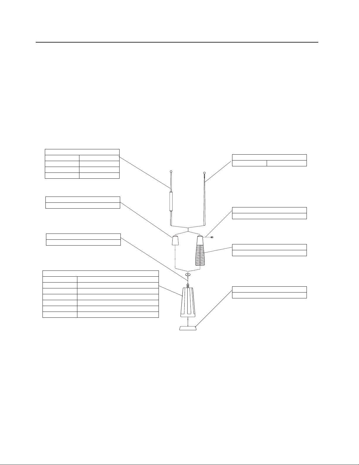
Assemble the antenna assembly (except the whip) onto the mounting base as shown in Figure 1.
1. Place the lock washer on stud loading coil/base housing.
2. Assemble either the standard duty or heavy duty spring adaptor to the base housing
assembly by threading onto the housing stud with lock washer already in place.
3. Hand tighten the adaptor until the lock washer is fully compressed.
4. Press rubber gasket onto the bottom of the coil housing.
5. Do not insert the antenna whip into the antenna adaptor at this time. Refer to the Tuning the
Antenna section on page 1-12 for further instructions.
Whip
01-80358A37 406 – 420 MHz
01-80358A38 445 – 470 MHz
01-80358A39 470 – 494 MHz
01-80358A40 494 – 512 MHz
Standard Duty Whip Adapter
58-80368B32
Lock washer
04-80378B70
Loading Coils/Base housing
01-80358A86 30 – 36 MHz
01-80358A87 36 – 42 MHz
01-80358A88 42 – 50 MHz
01-80358A89 66 – 88 MHz
01-80358A90 136 – 174 MHz
01-80358A91 406 – 512 MHz Heavy Duty Spring
01-80358A92 406 – 512 MHz Standard Duty
Whip
47-80369B56 30 – 174MHz
Set Screw
03-80374B24
Heavy Duty Spring
01-80373B34
Rubber Gasket
32-80369B53
Figure 1.
Mobile Antenna Installation 5
Antenna Mount Installation Instructions
Roof (Permanent 3/4” Hole) Mount Instructions
Tools Required:
• Safety glasses
• Hole saw (Motorola part # RPX-4378A)
• 15/16” open-end wrench
• Solder, 60/40 rosin flux
• Crimp tool, Motorola part # 66-80388A26 (Mini-UHF Connector only)
• Electric drill
• Spanner wrench, Motorola part # 66-80371A75
• Soldering iron, 40 – 75 watts
1. Drill a 3/4” hole in the vehicle with antenna hole cutting saw, Motorola part # RPX-4378A, and
remove all burrs. The antenna hold saw will remove paint in a narrow ring around hole to
assure good metal contact between vehicle and mount.
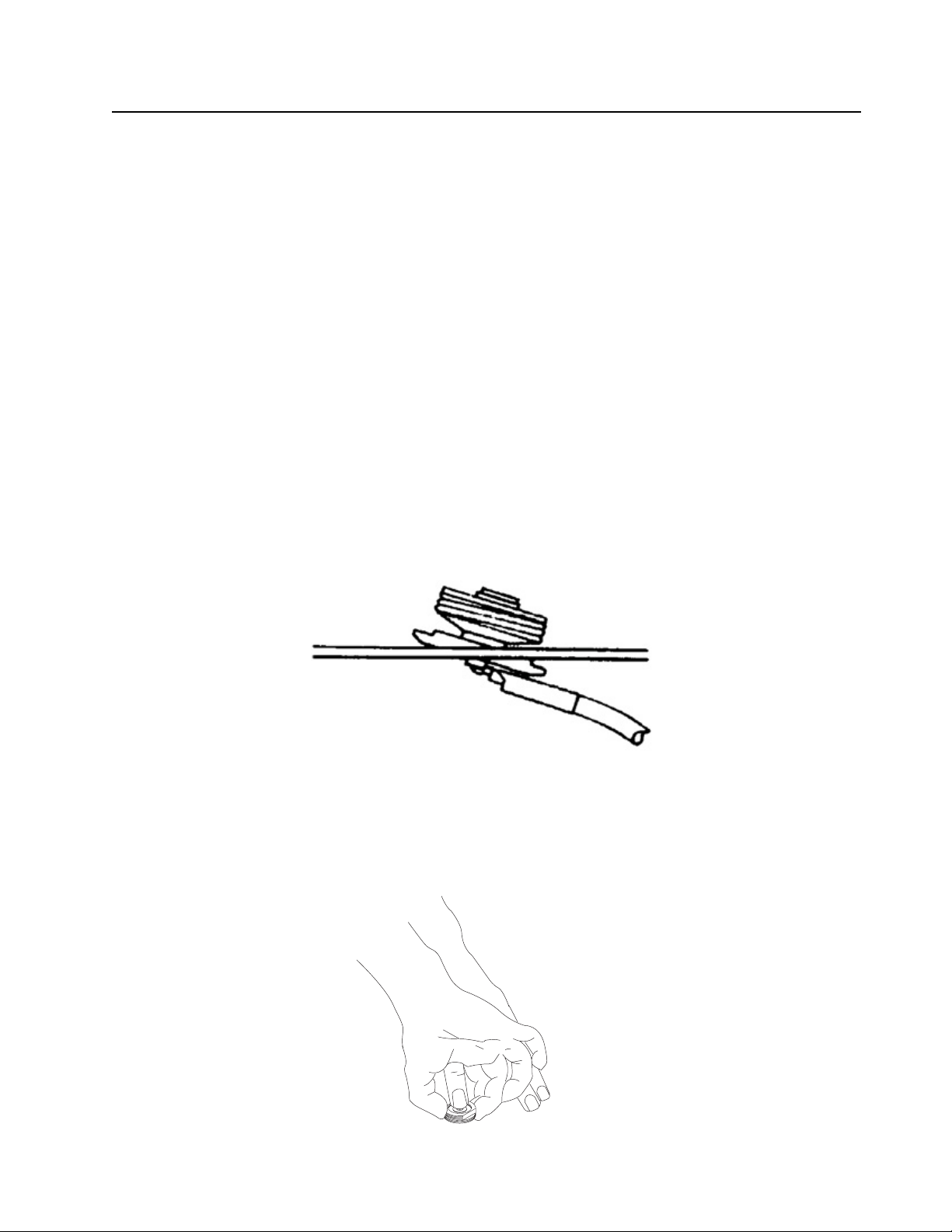
2. Apply generous amounts of silicon grease to inner and outer threads of brass lock nut. Feed
coaxial cable and mount through hole as shown in Figure 2.
Figure 2.
3. Thread locking nut onto mount and pull up mount base to properly align in hole. While pulling
up, finger tighten the locking nut against roof top as show in Figure 3.
MAEPF-27629-O
Figure 3.

6 Mobile Antenna Installation
43-83881B01 (Plated)
Holes for holding the Bushing
Locking Nut
O-Ring
42-83940B01
with Long Nose Pliers
Bushing Assembly
Cap Insulator
Cable
Car Roof
Paint removed in Ring
Figure 4.
4. Insert spanner wrench, part # 66-80371A75 or the tops of a needle nose pliers in bushing
assembly to prevent mount assembly from slipping. Use a 15/16” open-end wrench to tighten
locking but firmly against vehicle surface. The locking nut must be in contact with vehicle
metal to ensure proper antenna radiation. See Figure 4.
Trunk Lid Mount Installation
1. Trunk lid mount may be placed at the center of trunk lid near the rear window, or to the side,
preventing the antenna from hitting the rear window when raising the trunk lid. Be sure the
coaxial cable is not pinched under the mount clamp bracket. Refer to Figure 5.
2. Using the allen wrench supplied, tighten the set screws clockwise until the set screws break
through the paint, creating a good contact.
Figure 5. Coaxial Cable Insertion

Mobile Antenna Installation 7
3. Route coaxial cable from the trunk lid to the radio.
Magnet Mount Installation
Do not use magnet mount on vinyl roofs, magnet mount will not
properly hold the antenna on vehicle because holding power is
W A R N I N G
1. Remove all dirt and grime that will prevent magnet mount from seating securely.
2. Place magnet mount in final position. Sliding the mount may scratch paint surface.
3. Route coaxial cable to the radio,. Refer to Figure 6.
reduced. Magnet mount will not “hold on” to aluminum and nonmetallic surfaces.
Figure 6. Magnetic Mounted Base
Connector Installation
Before installing the connector, cut off any excess length of cable (at the radio end) to avoid
unnecessary signal loss. When the necessary preparations have been made, install the connector
using the following steps:
UHF Connector (Motorola part # 28-82021G01)
1. Disassemble the connector as shown in Figure 7A.
2. Cut off end of cable squarely and remove 3/4” of vinyl jacket. Refer to Figure 7B.
3. Slide coupling ring and adaptor on cable as in Figure 7C.
4. Fan braid slightly and fold back as shown in Figure 7D.
5. Position adaptor to dimension as shown in Figure 7E. Press braid back over body of adaptor
and trim to 3/8”. Base 5/8” of conductor. Tin exposed center conductor. Add teflon washer for
470 MHz and higher.
Use a hot soldering iron. DO NOT USE EXCESSIVE HEAT
OR SOLDER. Solder quickly to avoid melting surrounding
C a u t i o n
insulation.

8 Mobile Antenna Installation
6. Screw adaptor to the body of plug assembly. Solder braid to body of plus assembly through
holes. Solder center conductor of cable to plug contact of plug assembly. Refer to Figure 7F.
7. For final assembly, screw coupling on plug assembly.
8. Connect cable to antenna connector on radio set. Tighten coupling ring cross section of final
assembly as shown in Figure 7G.
NOTE: Coupling ring and plug sub assembly comprise of Motorola part number: 28-82021G01.
TEFLON Washer
(470MHZ and higher)
04-84506K01
A
Coupling
Ring
B
Adapter
58-854020
Plug
Sub-Assembbly
3”
4
C
Adapter
D
E
TEFLON Washer
(470MHZ and higher)
1/8” of Exposed Insulation
for Lower Frequencies
3”
4
3”
8
5”
8
F
G
Figure 7.

Mobile Antenna Installation 9
Mini-UHF Connector Installation #28-84606M01
Installation Instructions
Use Motorola tool part # 66-80388A26 (Refer to Figure 8).
1. Slip ferrule and collar onto cable. See Figure 10.
2. Prepare cable to strip dimensions as per Figure 11.
3. Insert stripped cable into plug body until conductor is exposed (front end) and dielectric
bottoms inside body. See Figure 10.
4. Crimp center contact using crimp area C of Figure 8 . Crimp at base of center contact, avoid
crimping at the tip. Refer to Figure 9.
5. Push collar forward onto plug assembly. Fit cable braid over support sleeve of connector. See
Figure 10.
6. Push ferrule over braid until flange butts against connector body. Refer to Figure 10. Using
the correct crimp area of tool, crimp ferrule close to plug body. Crimp ferrule for a second time
close to cable end.
7. Protuding center conductor should be trimmed with end of center contact.
FIVE CRIMP AREAS
A
B
.256
.319
C
D
.051
.068
.213
E
Figure 8. Motorola Crimping Tool 66-80388A26

10 Mobile Antenna Installation
Base of Pin
Suggested Crimp Area
Tip of Pin
2 mm
Figure 9. Coaxial Cable Stripping Dimensions
Flared
Braid
Connector
Body
Ferrule
Cable Inserted into
Connector Body
Protruding
Center
Conductor
Crimp Center
Contact after
Inserting Cable
Collar Slipped
Forward over
Connector Body
Figure 10.
Collar
Push Ferrule Forward
over Braid. Flange
Butts against Connector
Body. Crimp Ferrule to
Complete Crimp
MAEPF-27622-O

Mobile Antenna Installation 11
A
B
Frequency MHz Gain Duty
30 – 36 0 dB Standard 100
36 – 42 0 dB Standard 100
42 – 50 0 dB Standard 100
30 – 36 0 dB Heavy 100
36 –42 0 dB Heavy 100
42 – 50 0 dB Heavy 100
66 – 88 0 dB Standard 100
140 – 174 3 dB Standard 150
140 – 174 3 dB Heavy 150
406 – 420 5 dB Standard 150
445 – 470 5 dB Standard 150
470 – 495 5 dB Standard 150
495 – 512 5 dB Standard 150
406 – 420 5 dB Heavy 150
450 – 470 5 dB Heavy 150
470 – 496 5 dB Heavy 150
496 – 512 5 dB Heavy 150
406 – 420 5 dB Heavy 150
450 – 470 5 dB Heavy 150
470 – 496 5 dB Heavy 150
C
Figure 11.
Table 2 Spectrum Antennas
Max Power
Watts
Antenna Only Roof Mount Kit Trunk Lid Mount Kit Magnet Mount Kit
RAB-4002A RAB-4002ARA * * RAB-4002AMA
RAB-4003A RAB-4003ARA * * RAB-4003AMA
RAB4004A RAB-4004ARA * * RAB-4004AMA
RAB-4012A RAB-4012ARA * * RAB-4012AMA
RAB-4013A RAB-4013ARA * * RAB-4013AMA
RAB-4014A RAB-4014ARA * * RAB-4014AMA
RAC-4000A RAC-4000ATA * * RAC-4000AMA
RAD-4000A RAD-4000ARA RAD-400DATA RAD-4000AMA
RAD-4010A RAD-4010ARA RAD-401DATA RAD-4010AMA
With RG58 A/U Cable With RG58 A/U Cable With RG58 A/U Cable
RAE-4002A RAE-4002ARA RAE-4002ATA RAE-4002AMA
RAE-4004A RAE-4004ARA RAE-4004ATA RAE-4004AMA
RAE-4005A RAE-4005ARA RAE-4005ATA RAE-4005AMA
RAE-4006A RAE-4006ARA RAE-4006ATA RAE-4006AMA
With Low Loss Cable With Low Loss Cable
* * RAE-4002ARL RAE-4002ATL * *
* * RAE-4004ARL RAE-4004ATL * *
* * RAE-4005ARL RAE-4005ATL * *
* * RAE-4006ARL RAE-4006ATL * *
With RG58 A/U Cable With RG58 A/U Cable With RG58 A/U Cable
RAE-4012A RAE-4012ARA RAE-4012ATA RAE-4012AMA
RAE-4014A RAE-4014ARA RAE-4014ATA RAE-4014AMA
RAE-4015A RAE-4015ARA RAE-2015ATA RAE-4015AMA
Dim. A = 15/16"
Dim. B = 19/32"
Dim. C = 19/64"
MAEPF-27623-O

12 Mobile Antenna Installation
Table 2 Spectrum Antennas (Continued)
Frequency MHz Gain Duty
496 – 512 5 dB Heavy 150
406 – 420 5 dB Heavy 150
450 – 470 5 dB Heavy 150
470 – 496 5 dB Heavy 150
496 – 512 5 dB Heavy 150
NOTE: All antenna mount kits include RG58A/U Cable and PL259 Connector, except cable option that is listed otherwise. ** For low and
Mid Band Trunk lid mount kits, order antenna only and trunk lid mounting kit (01-80356A55) separately.
PART NUMBER ANTENNA MOUNTS
01-80352A03
01-80356A55
01-80356A47
01-80371A27
Roof Mount Kit, RG58A/U Cable, PL259 connector
Trunk Lid Mount, RG58A/U cable, PL259 connector
Magnet Mount RG58A/U cable, PL259 connector
Magnet Mount RG58A/U Cable PL259 connector, low band only
Tuning the Antenna
Max Power
Watts
Antenna Only Roof Mount Kit Trunk Lid Mount Kit Magnet Mount Kit
RAE-4016A RAE-4016ARA RAE-4016ATA RAE-4016AMA
With Low Loss Cable With Low Loss Cable
* * RAE-4012ARL RAE-4012ATL * *
* * RAE-4014ARL RAE-4014ATL * *
* * RAE-4015-ARL RAE-4015ATL * *
* * RAE-4016ARL RAE-4016ATL * *
Adjusting the whip length while radio is keyed may cause burns from
RF radiation.
W A R N I N G
NOTE: Tune antenna in an open area at least 12 feet away from any metal objects.
NOTE: Lengths shown on the cutting chart are approximate. Due to antenna variations and mounting
location effects, we recommend cutting the antenna rod 1 1/2” longer than the chart and then
cutting 1/2” off at a time until reflected power is minimized.
NOTE: DUE TO ANTENNA INTERACTION WITH VEHICLE, SOME LOW BAND ANTENNA
MOUNTING LOCATIONS WILL NEVER ACHIEVE 1.5:1 VSWR. In this case, trim the whip
for minimum reflected power. A simple table for converting the radio of forward power and
reflected power to VSWR is shown below in Tabl e 3 .
1. Locate the transmitter frequency on the cutting chart. In the case of multiple transmitter
frequencies, calculate the mid-frequency and locate on cutting chart. Read desired whip
length from the chart. Cut the whip 1 1/2” longer than this length.
NOTE: Trim the antenna rod (Low and High band) from the bottom only. On the UHF antenna whip,
trim the whip from the bottom of the rod below the phasing coil.
2. Use the set screw to secure the antenna whip in the whip adaptor assembly.
3. Using the in-line wattmeter, measure forward and reflected power at the desired transmit
frequency and calculate VSWR using Tab l e 3.
4. If VSWR is >1.5:1, then trim off 1/2” and repeat Step 3.
5. Repeat steps 3 and 4 until minimum VSWR is obtained.

Mobile Antenna Installation 13
6. Use the adjustment range of the whip in the adaptor in order to minimize the VSWR.
7. Insert the shorter part of the allen wrench into the screw and tighten the set screw at tight as
yo can by hand. If a torque wrench is available, tighten set screw to a torque of 25 – 30 inchlbs.
A simple table for converting the ratio of forward power and reflected power to VSWR is given below:
Table 3
Pfwd/Pref VSWR
440.6 1.1 : 1
58.8 1.3 : 1
25.0 1.5 : 1
14.9 1.7 : 1
10.4 1.9 : 1
7.9 2.1 : 1
Example: If the forward power (Pfwd) is measured as 100 watts and the reflected power (Pref) is 3
watts, calculate Pfwd/Pref = 33.3. Since 33.3 is between 25 and 58.8 m, the chart above indicated
that the VSWR is less than 1.5 : 1.

14 Spectrum™ by Motorola
Spectrum™ by Motorola
Cutting chart lengths are approximate. Whip length will wary with type of vehicle, mount location
and type of mount. Cut 1-1/2 inches longer than chart length, then trim for minimum reflected power.
Standard (No Spring) Heavy Duty Spring

Spectrum™ by Motorola 15
Standard (No Spring) Heavy Duty Spring

16 Spectrum™ by Motorola
Standard (No Spring) Heavy Duty Spring

Spectrum™ by Motorola 17
Spectrum™ by Motorola
Cutting chart lengths are approximate. Whip length will wary with type of vehicle, mount location
and type of mount. Cut 1-1/2 inches longer than chart length, then trim for minimum reflected power.
Standard (No Spring) Heavy Duty Spring

18 Spectrum™ by Motorola
Standard (No Spring) Heavy Duty Spring


M
Motorola Inc.
1301 E. Algonquin Rd.,
Schaumburg, IL 60196-1078, U.S.A.
MOTOROLA, the Stylized M Logo, and ASTRO are registered in the
U.S. Patent and Trademark Office. All other product or service names
are the property of their respective owners.
© 2000 – 2010 by Motorola, Inc.
All rights reserved.
*6880309C12*
6880309C12-F
 Loading...