

DIGITAL CHANNEL MODULE (CMD)
User’s Manual and Tune Up
Procedures
8A074X06
Rev. Preliminary
REVISION RECORD
REV # ECN # DESCRIPTION DATE
0 Preliminary Release August 1, 2003
PROPRIETARY STATEMENT
©
2003, Futurecom Systems Group Inc.
Printed in Canada. All Rights Reserved
No part of this document, or any software included with it, may be reproduced and distributed without the prior
written permission of the copyright holder.
Futurecom Systems Group Inc. reserves the right to make changes or improvements to the equipment, software
or specification described in this document at any time and without prior notice. These changes will be
incorporated in the new releases of this document.
This document may contain technical inaccuracies or typographical errors. Futurecom Systems Group Inc.
waves responsibility for any labour, materials or costs incurred by any party as a result of using this document.
8A074X06 Rev. Preliminary Page 2 of 15
21/08/2003

TABLE OF CONTENTS
About this document................................................................................................................ 4
Notes, Cautions, Warnings, Dangers................................................................................... 4
Safety Information................................................................................................................... 5
FCC Class A Digital Device or Peripheral User Information.............................................5
General Safety Information.................................................................................................5
Damage Requiring Service.............................................................................................. 6
Possible Hazards.............................................................................................................. 6
General Radio Operating Procedures ...................................................................................... 7
CMD Technical Description.................................................................................................... 8
Main Features ...................................................................................................................... 8
Principle of Operation.......................................................................................................... 9
CMD Installation (19” rack mount only)............................................................................... 10
CMD Programming............................................................................................................... 10
Introduction........................................................................................................................ 10
Connecting and Disconnecting the CMD to a PC............................................................. 10
Installing the Programming Software................................................................................ 10
Using the Programming Software for Setting up the CMD .............................................. 10
CMD Connections.........................................................................................................10
Starting up the Programming Software ......................................................................... 11
Programming the CMD Frequencies of Operation........................................................ 11
Programming the CMD Channel Spacing..................................................................... 12
Setting up the CMD Maximum Gain................................................................................. 13
CMD Front Panel Indicators.................................................................................................. 14
CMD Specifications............................................................................................................... 15
8A074X06 Rev. Preliminary Page 3 of 15
21/08/2003
About this document
This document describes the operation of the Futurecom Digital Channel Module (CMD). It
provides setup guidelines and outlines the programming options which are accessible
through the programming software (6A074X01).
Notes, Cautions, Warnings, Dangers
Throughout this manual, you will see Notes, Cautions, Warnings and Dangers.
Their meaning is as follows:
Note:
A clarifying statement that expands on the text that follows.
IMPORTANT:
An important statement that must be considered and / or implemented in
order to achieve adequate equipment operation.
WARNING:
Describes a potentially hazardous situation, which may lead to equipment
damage, death or injury.
DANGER:
Describes an imminently hazardous situation, which if not avoided,
death or serious injury.
will result in
8A074X06 Rev. Preliminary Page 4 of 15
21/08/2003
Safety Information
FCC Class A Digital Device or Peripheral User Information
NOTE:
This equipment has been tested and found to comply with the limits for a
Class A digital device, pursuant to Part 15 of the FCC Rules. These limits
are designed to provide reasonable protection against harmful interference
when the equipment is operated in a commercial environment. This
equipment generates, uses, and can radiate radio frequency energy and, if not
installed and used in accordance with the instruction manual, can cause harmful
interference to radio communications. Operation of this equipment in a residential area is
likely to cause harmful interference in which case the user will be required to correct the
interference at his own expense.
WARNING
Changes or Modifications not expressly approved by Futurecom Systems
Group Inc. could void the user’s authority to operate the equipment.
USA Users:
Do not use the Digital Channel Module in the frequency band 406.0 -
406.1MHz. This frequency band is reserved for use by distress beacons.
General Safety Information
The following information may or may not be applicable to your product.
In any case, precautions should always be taken when handling any electrical product.
IMPORTANT
This manual contains important safety and operating instructions, therefore keep
this manual always on hand!
Prior to using any product, follow all warning, safety and operating instructions
written on the product and in the user’s manual. All instructions should be
saved for reference in the future!
WARNING
Always keep product dry, never expose to any kind of moisture.
Do Not expose product to extreme temperatures- as found near a hot radiator or
stove.
Do Not expose product to open flames, cigarettes, etc.
Precautions should be taken to avoid objects falling or liquids spilling onto product.
Do Not incorporate the use of other equipment that is not recommended or sold by the
manufacturer. The result may be the risk of fire or electric shock injury.
Connect DC power cord to DC power source as marked on the product.
8A074X06 Rev. Preliminary Page 5 of 15
21/08/2003

This product does not contain customer serviceable components, therefore never
disassemble the product
IMPORTANT
If an outdoor antenna is connected, make sure the system is always grounded to
allow for protection against voltage surge and built-up static charges. Outdoor
antennas should always be located away from power lines.
DANGER
Never alter the AC cord or plug! If plug does not fit outlet have a qualified
electrician install a proper outlet. Failure to do so results in improper connection
and increases the risk of electric shock.
Damage Requiring Service
This product should be serviced by qualified service personnel when:
The power supply cord or the plug has been damaged; or
Objects have fallen, or liquid has been spilled into the product; or
The product has been exposed to rain or moisture; or
The product does not appear to operate normally or exhibits a marked change of
performance; or
The product has been dropped, or the cabinet damaged.
Possible Hazards
The operator of any mobile radio should be aware of certain hazards common to the
operation of vehicular radio transmissions.
A list of possible hazards follows:
Explosive Atmospheres
To ensure safety, make sure that the radio is off while fuelling the vehicle. When the
radio is mounted in the back of the trunk, never have containers of fuel in the trunk of
the vehicle.
Interference to Vehicular Electronics Systems
Typical types of electronic devices that malfunction are -Electronic fuel injection
systems, electronic anti-skid braking systems, etc., The reason for this is due to the lack
of protection from radio frequency energy present when transmitting. If the vehicle
contains such equipment, consult the dealer of your vehicle and enlist his aid in
determining if such electronic circuits perform normally when the radio is transmitting.
Dynamite Blasting Caps
Dynamite blasting caps may be caused to explode by operating a radio within 500 feet
of the blasting caps. Always obey the "Turn Off Two Way Radios" signs posted
where dynamite is being used. When transporting blasting caps in your vehicle:
A. Carry the blasting caps in a closed metal box with a soft lining.
B. Leave the radio OFF whenever the blasting caps are being put into or removed
from the vehicle.
8A074X06 Rev. Preliminary Page 6 of 15
21/08/2003

Radio Frequency Energy
Do not operate the transmitter when a person is outside of the vehicle within two feet of
the antenna! Failure to heed this warning may result in burns or related physical injury
to the person.
Liquefied (LP) Gas Powered Vehicles
Mobile radio installations in vehicles powered by liquefied petroleum gas with the LP
gas container in the trunk or other sealed-off space within the interior of the vehicle
must conform to the National Fire Protection Association standard (NFPA) 58
requiring that:
A. The space containing the radio equipment shall be isolated by a seal from the
space containing the LP gas container and its fittings.
B. Outside filling connections shall be used for the LP gas container.
C. The LP gas container shall be vented to the outside of the vehicle.
General Radio Operating Procedures
Industry Canada (IC) and the Federal Communications Commission (FCC) rules and
regulations must be incorporated in the use of radio systems. Familiarity with these rules by
the operator is essential for proper execution of the type of radio operation that is in
question. Following these rules helps to eliminate confusion, assures the most efficient use
of existing radio channels, and results in a smoothly functioning radio network. When using
this unit remember these rules:
A. Emergency calls always have priority over all messages! To interrupt any distress or
emergency message is a violation of the IC and FCC rules. When operating the radio
make sure that the line is clear before sending messages. KEEP OFF THE AIR
when an emergency message is being sent through.
B. Use of profane or obscene language is prohibited by Federal law.
C. Sending false call letters, false distress or emergency messages is against the law.
D. IC and FCC demand that conversations are kept brief and content limited only to
business. Coded messages are encouraged in order to save time.
E. Only messages that are essential for the business operations are allowed to be sent.
Otherwise using the radio to send personal messages is a direct violation of the IC
and FCC rules.
F. Conversations between others sharing a channel is regarded as confidential.
Repeating anything overheard on the radio is against Federal Law.
G. The IC and FCC require the operator to transmit station identification at certain times
by means of call letters. Refer to the IC and FCC rules for your station's particular
type of operation for the proper procedure.
H. No changes or adjustments shall be made to the equipment except by an authorized
or certified electronics technician.
8A074X06 Rev. Preliminary Page 7 of 15
21/08/2003

CMD Technical Description
Main Features
The Digital Channel Module (CMD) is a synthesized, microprocessor-based, high
performance, RF channel selective repeater with 30 Watt output power capability. It is
available in the VHF, UHF and 800/900MHz bands. It is designed to receive a single RF
channel, filter and amplify the channel signal and retransmit it. The CMD is used for
extending the RF Coverage area of an existing radio site by receiving and re-broadcasting
from host to user (downlink) and from user to host (uplink).
The CMD can be used in On-Channel Repeater (OCR) or Translator mode. In the Translator
mode, the CMD transmits on a frequency which is different from the receive frequency. The
On-Channel Repeater is programmed to receive and transmit on the same frequency.
The CMD operation is programmable locally from an RS-232 port on the front panel. The
CMD operating parameters, such as power output, sensitivity threshold, CTCSS, mode of
operation, frequencies of operation, adjacent channel spacing etc can be configured by the
Customer via simple set-up software as described in this manual. The currently programmed
operating parameters of the CMD determine its personality. The CMD personality is stored
in the EEPROM of the unit.
Additional per channel alarm and monitoring functions are available to indicate any Power,
VSWR, Temperature and Synthesizer lock conditions.
The CMD installation is performed by simply plugging it into a Eurocard format 19” EIA
rackmount card cage.
8A074X06 Rev. Preliminary Page 8 of 15
21/08/2003

Principle of Operation
The CMD consists of four main blocks – Front End, IF section, Power Amplifier and
Controller.
The Front End consists of band-pass filtering and low-noise amplifier. The sensitivity of the
Front End is -120dBm.
After the Front End, the RF frequency is downconverted to 109.65MHz by a mixer stage
followed by BP filtering, amplification and another mixer downconverting to IF 450kHz.
The IF signal path continues with an Automatic Gain Control Loop (AGC), which maintains
constant signal level, irrespective of the input signal level. The processed signal is fed to a
modulator and Upconverter. The upconverted signal (110.520MHz) goes through selective
filters and amplifier stages, followed by a mixer, which further upconverts it to the
programmed CMD transmit frequency (same as the receive in the OCR or different
frequency in the Translator mode). The transmit frequency signal is fed to the power
amplifier module where it is filtered and amplified. The driver and power amplifier produce
the programmed transmit power output (max 30 Watts).
The Controller Board controls the operation of the CMD. It contains the microcontroller
with Flash memory for the firmware, EEPROM personality storage.
The front panel RESET and TX DISABLE inputs are monitored and can be accesses via two
front panel holes with a round tool 2.5mm (0.1”) diameter. The front panel indicators (TX
DIS, DC ON, TX ON, RX ON, PWR and VSWR) are also controlled by the Controller
Board.
8A074X06 Rev. Preliminary Page 9 of 15
21/08/2003

Slave CMDs
lave Shelf
CMD Installation (19” rack mount only)
The CMD is easily installed by plugging it into the Eurocard format card cage.
The CMD is powered through its card cage back plane. The card cage back plane DC wiring
must be connected to nominal 27.6VDC.
CMD Programming
Introduction
The Controller board EEPROM of the CMD contains the programmed Personality Data
(PD) of the specific CMD unit. The PD file determines the functionality of the CMD and it
can be created and / or modified by using the CMD programming software.
Connecting and Disconnecting the CMD to a PC
1. Plug the supplied programming cable into the “RS232” connector on the front of the
CMD.
2. Plug the other end of the serial cable into the serial port of the PC.
3. Follow the Programming Instructions as described in the next paragraphs.
4. Exit the programming software and only then unplug the serial cable from the CMD.
Installing the Programming Software
The programming software can be run either from Windows or MS DOS. Copy the files
from the Futurecom supplied disk into a separate directory / folder on your PC. Create a
shortcut (Windows) or use the supplied batch file by typing in the path to the .exe file
location on the specific PC. Run the programming software by clicking on the shortcut or
typing the batch file name.
Using the Programming Software for Setting up the CMD
CMD Connections
The CMD needs to be properly connected prior to commencing the programming /
system setup:
1. The CMD must be plugged into the Futurecom subrack and supplied with proper
DC power supply.
2. The RF IN and RF OUT ports need to be connected to the corresponding
multicoupling ports or to adequate power rating 50 Ohm loads (or to the test
equipment).
3. The DC power supply needs to be turned on.
8A074X06 Rev. Preliminary Page 10 of 15
21/08/2003

Starting up the Programming Software
After connecting the programming cable to the CMD serial port, run the programming
software. Go to the Options pull down menu and select Ports. The following screen will be
displayed:
Ensure that
higher Baud rate is selected, ensure that the Baud rate scanning is set to Enable. Exit
from the Ports menu and select “Yes” when prompted “Would you like to update config
file?”
Progr
Go to File, select Upload Data from the CMD and press E
The programming software uploads the currently stored in the CM
CMD Channel Setup screen will be displayed:
the correct communication port is selected and set the Baud rate to 9600 b/s. If
amming the CMD Frequencies of Operation
nter.
D EEPROM data and the
8A074X06 Rev. Preliminary Page 11 of 15
21/08/2003
Important:
When progr
CMD, the user will be asked “Would you like to update the EEPROM” every
time he / she tries to close the currently open programming screen. Select
“Yes” if the changes need to be kept after the CMD is reset. For some of the
changes to take effect the CMD must be reset.
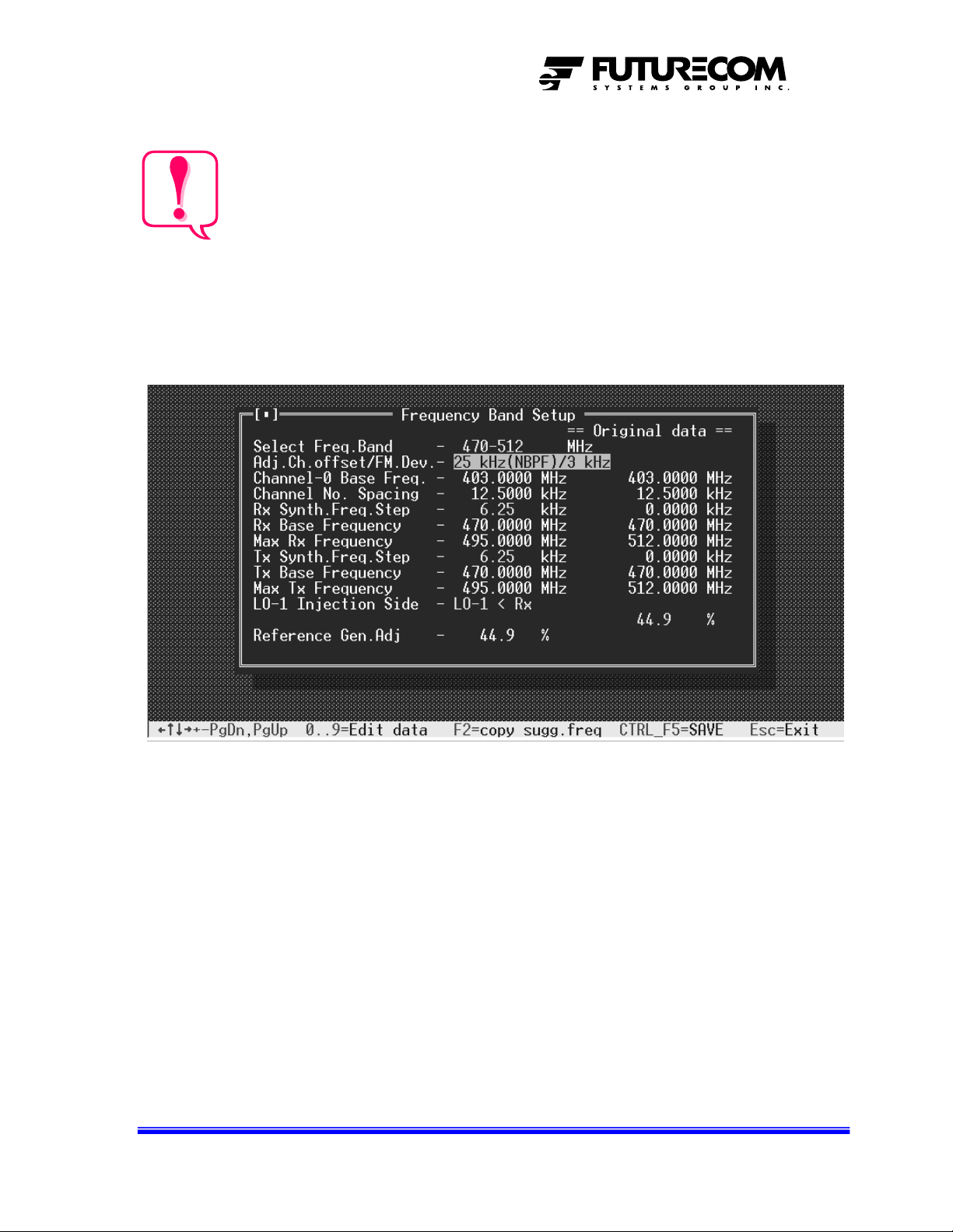
rogramming the CMD Channel Spacing
P
Prior to setting up the rest of the CMD paramete
selected. This is done from the Frequency Band Setup in the CMD Setup pull down menu.
amming (or editing the personality of) the currently connected
rs, the global channel spacing needs to be
Adjust the Adj. Ch. Offset / FM Dev field to the correct channel spacing i.e. 25kHz
(NBPF)/3kHz or 12.5kHz / 1.5kHz. All other fields must not be changed by the user.
8A074X06 Rev. Preliminary Page 12 of 15
21/08/2003

Setting up the CMD Maximum Gain
The CMD can be used either as an On Channel Repeater (OCR) or as a translator. In the
OCR mode, the CMD receive and transmit frequency is the same as opposed to the
Translator mode, in which the receive and transmit frequencies are different. The Gain range
is 70 to 140dB in OCR mode and 70 to 165dB in Translator mode. However, the gain is
limited by the isolation that can be achieved between the rest of the RF system i.e. cables,
antennas, filtering etc. The maximum Gain setting must be at least 10 dB lower than the
measured overall isolation in order to prevent CMD lock up.
Once the CMD is programmed, installed and connected to the rest of the filtering / antenna
system, the Maintenance screen can be used for measuring the isolation and setting up the
gain. No extra test equipment is required.
Open the Maintenance screen from the CMD Setup pull down menu. The Maintenance
screen is not a programming screen. It is used for diagnostic and setup only. The fields seen
on the Maintenance screen are described in the previous sections with the exception of the
measured data fields shown on the right hand side and marked with “?”.
8A074X06 Rev. Preliminary Page 13 of 15
21/08/2003

CMD Front Panel Indicators
The CMD front panel has several LEDs which provide the following indications:
LED
Label
TX DIS RED The TX DIS LED is steady on when
DC ON GREEN When on it indicates that the CMD is
TX ON GREEN When on it indicates that the CMD is
RX ON GREEN When on it indicates that the CMD input
PWR RED The PWR LED is steadily on when
VSWR RED The VSWR LED is on when an excessive
LED
Color
DESCRIPTION
transmit is disabled either by:
Triggering the TX DIS switch which
is located above the LED (accessible
with a round tool 2.5mm in diameter)
Setting the Operating Mode field to
Tx-Disable
The TX LED indicator is flashing when one
of the synthesizers is being out of lock.
powered up.
transmitting.
signal is above the programmed level
the output RF power is outside of the
programmed tolerance.
reflected power is detected on the Tx port
8A074X06 Rev. Preliminary Page 14 of 15
21/08/2003

CMD Specifications
ELECTRICAL SPECIFICATIONS
Frequency of Operation 136 – 174 MHz 403 – 512 MHz 806 – 960 MHz
Sensitivity -120 dBm -117 dBm
Input Carrier Detection Threshold -120 to -50 dBm -117 to -50 dBm
Carrier Detection Adjustment Step 1 dB
Max. Gain Range (Programmable)
Translator
On-Channel Repeater
AGC Range 100 dB
Output Power
Duty Cycle 100%
Output Frequency Stability Tracks Input Signal Frequency
Modulation Types Narrowband FM Voice and Data
Channel Spacing 25 kHz / 12.5 kHz
Selectivity 25kHz / 12.5kHz >80 / > 70dB
Receiver Spurious Response Rejection > 70 dB
Receiver Conducted Spurious
Emissions
Transmitter Conducted Spurious
Emissions
Transmitter FM Hum and Noise > 45 dB
Input / Output Impedance 50 Ohms
Input / Output VSWR < 1.5 : 1
Power Supply Voltage 22 to 28 VDC
Power Supply Current Drain
Standby
Transmit
MECHANICAL SPECIFICATIONS
RF Connectors SMA female
Environmental 90% humidity @ 50 °C (122°F)
Operating Temperature Range -30 to +60°C (-22 to +140°F)
Dimensions [H x D x W] 260 x 225 x 75 mm (10.25” x 8.86” x 2.95”)
Weight 4.09 kg (9 lb)
CMD VHF CMD UHF CMD 800
70 to 165 dB
70 to 140 dB
75 mili-Watts to 35 Watts
< -57 dBm
< -20 dBm
< 0.3 A
< 4 A
8A074X06 Rev. Preliminary Page 15 of 15
21/08/2003
 Loading...