

Page 1

January 2019 Page 1 of 94
Futurecom Systems Group, ULC
DVRS
User’s Guide
Page 2

8A083X30 Rev.11
APX Series P25 Interface
DVRS User’s Guide
January 2019 Page 2 of 94
NOTES
Page 3

8A083X30 Rev.11
APX Series P25 Interface
DVRS User’s Guide
January 2019 Page 3 of 94
Contents
Contents ........................................................................................................................ 3
Foreword ........................................................................................................................ 8
Manual Revisions ........................................................................................................ 8
Firmware ..................................................................................................................... 9
Computer Software Copyrights .................................................................................... 9
Document Copyrights .................................................................................................. 9
Disclaimer ................................................................................................................... 9
Trademarks ................................................................................................................. 9
Commercial Warranty and Service ............................................................................ 10
Notations Used in This Manual .................................................................................. 11
Declaration of Conformity .......................................................................................... 12
RF Energy Exposure Compliance, Awareness and Control Information and
Operational Instructions ................................................................ ............................. 13
Introduction ................................................................................................................. 14
Identifying Your DVRS Model .................................................................................... 15
Frequency Band of Operation ............................................................................................... 15
Cross-Band ........................................................................................................................... 15
In-Band.................................................................................................................................. 18
Band Locking ........................................................................................................................ 21
P25 Tactical Repeater with Backpack option ....................................................................... 22
DVRS Operation Basics .............................................................................................. 23
DVRS Features by PSU Type – Motorola Infrastructure ............................................ 24
‘DVRS Enabled’ PSU Features Support in Non-Motorola Infrastructure .................... 25
Powering up the DVRS .............................................................................................. 26
Turning ON the DVRS ............................................................................................... 26
Activating the DVRS via the Control Head ........................................................................... 26
Automatic DVRS Activation (AVRA) ..................................................................................... 27
Remote Activation of the DVRS ............................................................................................ 28
Turning OFF the DVRS ............................................................................................. 30
Deactivating the DVRS via the MSU Control Head .............................................................. 30
Deactivating the DVRS via Call Alert sent by Dispatch ........................................................ 30
Automatic DVRS Deactivation .............................................................................................. 31
DVRS Status Display................................................................................................. 32
DVRS Enabled PSUs ................................................................................................ 33
Page 4

8A083X30 Rev.11
APX Series P25 Interface
DVRS User’s Guide
January 2019 Page 4 of 94
DVRS Status Tones .................................................................................................. 34
DVRS Status Tones - MSU Speaker .................................................................................... 34
DVRS Status Tones - PSU ................................................................................................... 35
‘DVRS Enabled’ Mobile Radio TGs / Channels.......................................................... 37
‘DVRS Disabled’ Mobile Radio TGs / Channels ......................................................... 37
In Car Monitor (ICM) .................................................................................................. 38
Primary / Secondary Operation Basics ...................................................................... 39
Permanent Primary Activation .............................................................................................. 41
Permanent Primary Deactivation .......................................................................................... 41
Legacy Mobexcom II Voting Compatibility Mode .................................................................. 41
DVRS Modes of Operation ........................................................................................ 42
OFF Mode ............................................................................................................................. 42
SYSTEM Mode ..................................................................................................................... 42
LOCAL Mode ........................................................................................................................ 43
Selecting DVRS Mode ............................................................................................... 44
Selecting DVRS Mode from the Control Head...................................................................... 44
Strapped DVRS Mode .......................................................................................................... 44
Selecting DVRS Channel .......................................................................................... 44
Independent DVRS Channel Change ................................................................................... 44
Strapped DVRS Channel Change ........................................................................................ 44
MSU Scan ................................................................................................................. 46
Supported MSU Scan Types ................................................................................................ 46
DVR Enabled / Disabled Rules while MSU Scan is enabled ................................................ 46
Outbound Calls (received by MSU from the FNE) with MSU Scan Enabled ........................ 46
Inbound Calls (received by DVRS from PSU) with MSU Scan Enabled .............................. 46
MSU ISSI Roaming ................................................................................................... 47
Unsupported PSU Features....................................................................................... 47
P25 Digital Mode Operation ........................................................................................ 49
PSU Affiliation ........................................................................................................... 50
Group Calls ............................................................................................................... 50
MSU Priorities ........................................................................................................... 50
PSU Proxy Request Priorities .................................................................................... 50
Signaling Request Interactions with Voice and Signaling Proxy ................................. 51
Voice Request Interaction with Signaling and Voice Proxy ........................................ 52
MSU Voice and Signaling Proxy Interactions ............................................................. 54
Talk Group Proxying .................................................................................................. 54
Talk Group Translation .............................................................................................. 54
Private Calls .............................................................................................................. 55
PSU Talk Permit Tones ............................................................................................. 55
Status Broadcast ....................................................................................................... 55
Page 5

8A083X30 Rev.11
APX Series P25 Interface
DVRS User’s Guide
January 2019 Page 5 of 94
Local Mode Indication................................................................................................ 56
Radio Check / Inhibit ................................................................................................. 56
P25 Trunking OTAR .................................................................................................. 56
Patch ................................................................ ......................................................... 56
Dynamic Regrouping ................................................................................................. 57
Phone Interconnect ................................................................................................... 57
Adaptive Power Control ............................................................................................. 57
Digital Audio Buffering ............................................................................................... 57
P25 Encryption .......................................................................................................... 58
Remote DVR Activation and Steering by PSU Call Alert (Page) ................................ 59
Emergency in Digital Mode ........................................................................................ 61
Emergency Alarm ................................................................................................................. 61
Emergency Call ..................................................................................................................... 62
Emergency Revert through DVR .......................................................................................... 62
Emergency Revert through PSU .......................................................................................... 62
Emergency operation during TG Translation ........................................................................ 62
Fireground (FG) Signaling ......................................................................................... 63
PSU IV&D ................................................................................................................. 63
PSU Location Reporting ............................................................................................ 63
PSU Call Alert ........................................................................................................... 63
PSU Message ........................................................................................................... 63
PSU Status Update and Status Request ................................................................... 63
Automatic PSU Revert to Talk Around (TA) ............................................................... 64
PSU Group Services ................................................................................................. 64
Group Text ............................................................................................................................ 64
Group Alias Update ............................................................................................................... 65
Digital Mode – Summary of Features ........................................................................ 66
Digital DVR Mode with P25 Trunking Mode Selected on MSU ............................................ 66
Digital DVR Mode with P25 Conventional Mode Selected on MSU ..................................... 67
Forced Analog Mode ................................................................................................... 68
Leading & Trailing Tones ........................................................................................... 68
Forced Analog All DVR Mode- Operation and Programming Overview ..................... 69
Forced Analog Mode – Summary of Features ........................................................... 70
Forced Analog DVR Mode with Conventional Analog Mode Selected on MSU ................... 70
Forced Analog DVR Mode with 3600 Trunking Mode Selected on MSU ............................. 71
Forced Analog DVR Mode with P25 Trunking TDMA Mode Selected on MSU ................... 72
Analog Mode Operation .............................................................................................. 73
DVR Channel Setup for Analog Mode ....................................................................... 73
Page 6

8A083X30 Rev.11
APX Series P25 Interface
DVRS User’s Guide
January 2019 Page 6 of 94
Group Calls ............................................................................................................... 73
Emergency in Analog Mode....................................................................................... 74
Emergency Alarm ................................................................................................................. 74
Emergency Call ..................................................................................................................... 74
Emergency Revert through DVR ............................................................................... 75
Analog Audio Buffering .............................................................................................. 75
Tactical Public Safety (TPS) ................................ ...................................................... 75
Fireground (FG) Signaling ......................................................................................... 75
Remote DVRS Activation via DTMF .......................................................................... 76
P25 Encryption in Analog Mode ................................................................................ 76
Mobile Mode Steering via PL/DPL ............................................................................. 76
Steering and Emergency ...................................................................................................... 76
MSU Operating on TDMA (P25, Phase 2) ................................................................. 77
Analog Mode – Summary of Features ....................................................................... 78
Analog DVR Mode with P25 Trunking Mode Selected on MSU ........................................... 78
Analog DVR Mode with P25 Conventional Mode Selected on MSU .................................... 79
Analog DVR Mode with Conventional Analog Mode Selected on MSU ............................... 80
Analog DVR Mode with 3600 Baud Analog or Digital Trunking Mode Selected on MSU .... 81
Analog DVR Mode with P25 Phase II (TDMA) Trunking Mode Selected on MSU ............... 82
Mixed DVRS Mode ....................................................................................................... 83
Special Features Support ........................................................................................... 84
TPS Signaling ........................................................................................................... 84
Troubleshooting .......................................................................................................... 85
Appendix 1 – DVR Specifications .............................................................................. 86
Contact Information .................................................................................................... 88
Glossary ....................................................................................................................... 89
Index ............................................................................................................................ 92
Page 7

8A083X30 Rev.11
APX Series P25 Interface
DVRS User’s Guide
January 2019 Page 7 of 94
List of Tables
Table 1 DVRS vs Infrastructure Compatibility ................................................................ 14
Table 2 DVRS Features vs Type of PSU ....................................................................... 24
Table 3 'DVRS Enabled' PSU Features Support on Non-MSI Infrastructure .................. 25
Table 4 AVRA Functionality ........................................................................................... 27
Table 5 DVRS Status Display Messages / Icons ........................................................... 32
Table 6 DVRS Enabled PSU Models ............................................................................. 33
Table 7 DVRS Status Tones (MSU Speaker) ................................ ................................ 34
Table 8 P25 DVRS Enabled PSUs – DVRS Specific Tones .......................................... 35
Table 9 Analog PSU - DVRS Specific Tones ................................................................. 36
Table 10 Primary DVR Definitions ................................ ................................................. 40
Table 11 OFF Mode DVRS Basic Operation ................................................................. 42
Table 12 SYSTEM Mode DVRS Basic Operation .......................................................... 42
Table 13 LOCAL Mode DVRS Basic Operation ............................................................. 43
Table 14 MSU Proxy Request Priorities ........................................................................ 50
Table 15 PSU Proxy Request Priorities ......................................................................... 50
Table 16 Signaling Request Interaction with Signaling Proxy ........................................ 51
Table 17 Signaling Request Interaction with Voice Proxy .............................................. 51
Table 18 Voice Request Interactions with Signaling Proxy ............................................ 52
Table 19 Voice Proxy Interaction with Voice Proxy ........................................................ 53
Table 20 Inbound P25 Encryption Rules ....................................................................... 58
Table 21 Outbound P25 Encryption Rules ..................................................................... 58
Table 22 MSU MIC PTT P25 Encryption Rules ............................................................. 58
Table 23 Typical Remote Steering Scenarios ................................................................ 60
List of Figures
Figure 1 Cross-Band Full Duplex & Simplex Capable DVRS - Conceptual Diagram...... 15
Figure 2 Cross-Band Simplex Only Capable DVRS - Conceptual Diagram ................... 16
Figure 3 Vehicular Mount Cross Band DVRS Model – Full Duplex & Simplex Capable . 17
Figure 4 Vehicular Mount Cross Band DVRS Model - Simplex Only Capable ............... 17
Figure 5 In-Band Full Duplex / Simplex Capable DVRS - Conceptual Diagram ............. 19
Figure 6 In-Band Simplex Only Capable DVRS - Conceptual Diagram ......................... 19
Figure 7 Vehicular Mount In-Band 700 or 800MHz DVRS Model - Full Duplex & Simplex
Capable.................................................................................................................. 20
Figure 8 Vehicular Mount In-Band VHF or UHF DVRS Model - Full Duplex & Simplex
Capable.................................................................................................................. 20
Page 8
8A083X30 Rev.11
APX Series P25 Interface
DVRS User’s Guide
January 2019 Page 8 of 94
Foreword
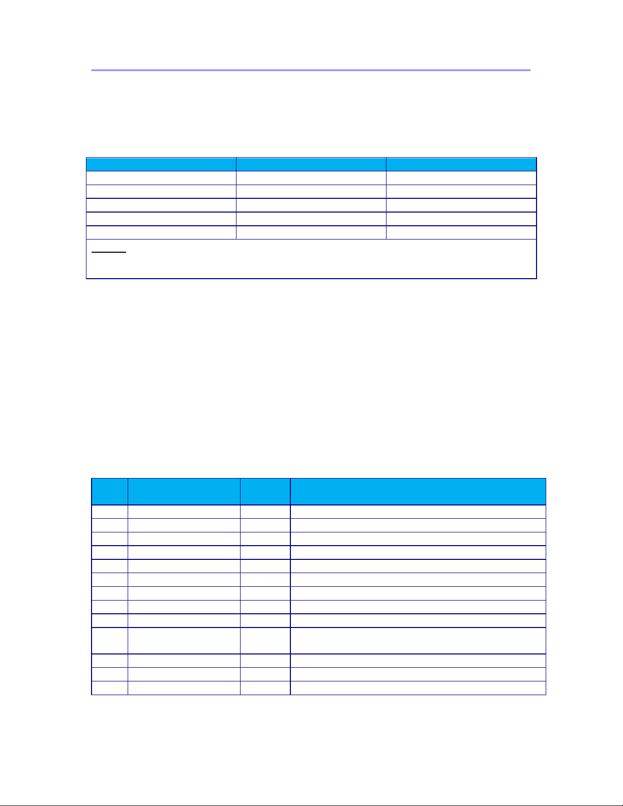
This manual provides User guidelines for the Futurecom P25 Digital Vehicular Repeater
(DVR) interfaced to a remote mount Motorola APX mobile radio:
Mobile Radio Model
Firmware Requirements
Notes
APX2500
R19.00.00 or later
Requires option GA00631
APX4500
R19.00.00 or later
Requires option GA00631
APX6500
R19.00.00 or later
Requires option GA00631
APX7500
R19.00.00 or later
Requires option GA00631
APX8500
R19.00.00 or later
Requires option GA00631
NOTE:
Mobile Radio must be configured as Remote Mount in order to be compatible with the
DVRS.
When the DVR is interfaced to a compatible P25 capable Motorola Mobile Radio, the
complete equipment package is referred to as Digital Vehicular Repeater System
(DVRS).
The DVR may also be used as a standalone (Tactical) repeater. The operation of the
Tactical DVR is described in publication 8A083X21.
For details on the APX Interfaced DVRS Installation and Programming Guidelines,
please refer to publication 8M083X025.
For details on the Motorola APX series mobile radios, please refer to the applicable
User’s Manuals available from Motorola.
Manual Revisions
Rev
#
Date
By
Notes & References
0
July 2, 2013
KG
Original Release
1
December 8, 2014
KG
Firmware R1.10 Update
2
July 22, 2015
KG
Firmware R1.20 / SR7.15.5 Update
3
September 3, 2015
KG
Removed APX2500/APX4500
4
October 14, 2015
KG
Firmware R1.21 / R14.04.00 Update
5
February 10, 2016
KG
Firmware R1.22 / R14.50.00 Group Services
6
October 11,2016
AJK/SN
Firmware R1.30/SR7.17 Update
7
February 28,2017
AJK/SN
Removed APX2500/APX4500
8
April 17, 2017
AJK/SN
Firmware R1.40/ SR 7.17.5 Update
9
January 15,2018
AJK/SN
Firmware R1.41/SR 7.18 Update
FCC/ISED Update
10
June 11, 2018
AJK/SN
Firmware R1.42/SR 7.18.5 Update
11
January 28, 2019
AJK/SN
Firmware R1.43/SR 7.18.8 Update
Page 9

8A083X30 Rev.11
APX Series P25 Interface
DVRS User’s Guide
January 2019 Page 9 of 94
Firmware
The DVRS Operation described in this Document requires the following Firmware:
APX Mobile Radios - firmware release: Host R19.00.00 or later.
APX Mobile Radios operating as the host mobile for the DVR require subscriber option
GA00631 for operation.
XTS1500 / XTS2500 / XTS5000 - firmware release R17.01.01 or later.
APX2000 / APX4000 / APX6000 / APX7000 / APX8000 – firmware release R19.00.00 or
later.
APX Portable Radios operating through a DVR, utilizing the enhanced DVR digital
feature set require subscriber option QA00631.
DVR must be loaded with firmware release:
Application 4C083X11 R1.43 or later.
Tweaker Programming software 6A083X05 – Version 1.18 or later.
Computer Software Copyrights
The products described in this manual include copyrighted Futurecom computer
programs stored in semiconductor memories or other media. Laws in the United States,
Canada and other countries preserve for Futurecom certain exclusive rights for
copyrighted computer programs, including but not limited to, the exclusive right to copy
or reproduce in any form the copyrighted computer programs. Any copyrighted computer
program contained in the Futurecom products described in this manual may not be
copied, reproduced, modified, reverse-engineered, or distributed in any manner without
the express written permission of Futurecom. The purchase of Futurecom products shall
not be deemed to grant either directly or by implication, estoppels, or otherwise, any
license under the copyrights, patents or patent applications of Futurecom, except for the
normal non-exclusive license to use that arises by operation of law in the sale of a
product.
Document Copyrights
No part of this manual may be reproduced, distributed or transmitted in any form or by
any means, for any purpose without written permission of Futurecom.
Disclaimer
The information in this document is carefully examined and is believed to be entirely
reliable. However, no responsibility is assumed for inaccuracies.
Futurecom Systems Group, ULC. reserves the right to make changes to any products
herein to improve reliability, function or design. Futurecom does not assume any liability
arising out of the application or use of any product or circuit described herein.
Trademarks
MOTOROLA, ASTRO, XTLTM2500, XTLTM5000, XTSTM1500, XTSTM2500, XTSTM5000,
APXTM4000, APXTM6000, APXTM7000, APXTM8000,APXTM2500,APXTM4500, APXTM6500,
APXTM7500, APXTM8500, MDC1200 are trademarks of Motorola Solutions Inc.
Page 10

8A083X30 Rev.11
APX Series P25 Interface
DVRS User’s Guide
January 2019 Page 10 of 94
Commercial Warranty and Service
Futurecom Systems Group, ULC. warrants to the original purchaser all standard
products sold by Futurecom Systems Group, ULC. to be free of defects in material and
workmanship for one (1) year from the date of shipment from Futurecom Systems Group
ULC.
Futurecom’s warranty hereunder DOES NOT cover the following :
(i) Defects or damage resulting from use of the product in other than its normal
and customary manner.
(ii) Defects or damage from improper installation, testing, operation, or
maintenance.
(iii) Defects or damage due to alterations, modifications or adjustments carried
out by the Buyer without Futurecom’s explicit approval.
(iv) Defects or damage from misuse, accident, water or neglect.
(v) Freight costs to the repair depot.
(vi) Scratches or other cosmetic damage to the product surfaces that does not
affect the operation of the product.
(vii) Normal wear and tear.
The warranty set forth herein is conditioned upon proper storage, installation, use and
maintenance in accordance with applicable written recommendation of Futurecom. The
warranty furnished hereunder does not extend to damage to items purchased hereunder
resulting in whole or in part from the use of components, accessories, parts of supplies
not furnished by Futurecom Systems Group, ULC.
Futurecom’s sole obligation shall be to repair or replace, at Futurecom’s option, any
defective component or item and pay transportation expenses for such replacement at
no charge to Buyer who shall provide labor for the removal of the defective component
or item and installation of its replacement at no charge to Futurecom. Buyer shall bear
all risk of loss or damage to returned goods while in transit. In the event no defect or
breach of warranty is discovered by Futurecom upon receipt of any returned item, the
item will be returned to Buyer at Buyer’s expense and Buyer will reimburse Futurecom
for the transportation charges, labor and associated charges incurred in testing the
allegedly defective item.
Except as expressly provided herein, Futurecom makes no warranty of any kind,
expressed or implied, with respect to any goods, parts and service provided by
Futurecom including, but not limited to, the implied warranties or merchantability and
fitness for a particular purpose. The sole and exclusive remedy for breach of any
warranty is limited to the remedies provided in the paragraph above. Futurecom shall
not in any event be liable for any other damages arising out of or in connection with
furnishing of goods, parts or service hereunder, or the performance, use of, or inability to
use any goods, parts or service, or otherwise, whether based on contract, tort or any
other legal theory.
To exercise this warranty, please contact Futurecom’s Administration Department in
Concord, Ontario, Canada at 1-800 701 9180 to obtain a return material authorization
(RMA) and shipping instructions. No product will be accepted for return without an RMA.
The repair of a product by Futurecom pursuant to this warranty is warranted for the
balance of the original warranty period, or at least 90 days from date of shipment to
Buyer of the repaired product.
Page 11

8A083X30 Rev.11
APX Series P25 Interface
DVRS User’s Guide
January 2019 Page 11 of 94
Notations Used in This Manual
The following notations are used throughout this document:
NOTE:
A clarifying statement that expands on the text that follows.
IMPORTANT!
An important statement that should be considered and / or implemented in order
to achieve adequate equipment operation.
ATTENTION!
An instruction that must be followed to insure compliance with the appropriate
standards or proper equipment operations.
Page 12
8A083X30 Rev.11
APX Series P25 Interface
DVRS User’s Guide
January 2019 Page 12 of 94
Declaration of Conformity
This equipment has been tested and found to comply with the limits for a Class A digital
device, pursuant to Part 15 of the FCC Rules. These limits are designed to provide
reasonable protection against harmful interference when the equipment is operated in a
commercial environment. This equipment generates, uses, and can radiate radio
frequency energy and, if not installed and used in accordance with the instruction
manual, may cause harmful interference to radio communications. However, there is no
guarantee that interference will not occur in a particular installation.
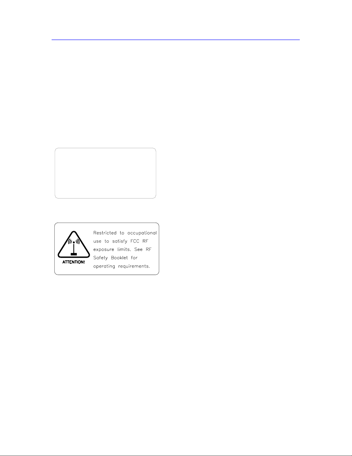
FCC Label
including interference that may cause undesired
2) This device must accept any interference received,
1) This device may not cause harmful interference, and
Operation is subject to the following two conditions:
This device complies with Part 15 of the FCC Rules.
operation.
RF Exposure Label
Page 13

8A083X30 Rev.11
APX Series P25 Interface
DVRS User’s Guide
January 2019 Page 13 of 94
RF Energy Exposure Compliance, Awareness and
Control Information and Operational Instructions
ATTENTION!
Changes or modifications not expressly approved by Futurecom Systems Group,
ULC. could void the User’s authority to operate the equipment. To satisfy
FCC/ISED RF exposure requirements for mobile transmitting devices, the
minimum separation distances specified in the RF Safety Booklet 8F083X03(FCC)
or 8F083X05(ISED) shipped with the DVRS should be maintained. To ensure
compliance, operations at closer than this distance is not allowed.
ATTENTION!
Futurecom requires the P25 DVRS operator to ensure FCC/ISED Requirements for
Radio Frequency Exposure are met. The minimum distance between all possible
personnel and the body of the DVRS equipped vehicle is specified in the “RF
Safety” book shipped with the DVR. Failure to observe the Maximum Permissible
Exposure (MPE) distance exclusion area around the antenna may expose persons
within this area to RF energy above the FCC exposure limit for bystanders
(general population). It is the responsibility of the repeater operator to ensure MPE
limits are observed at all times during repeater transmissions. The repeater
operator must ensure at all times that no person comes within MPE distance from
the vehicle body.
ATTENTION!
The Transportable (suitcase) DVRS ships without an APX Mobile radio. Once an
APX Mobile radio is installed, refer to the Product Safety and RF Exposure booklet
8F083X03(FCC) or 8F083X05(ISED) enclosed with your DVRS. Refer to the vehicle
installation guidelines for vehicle installation. For fixed site installation, refer to
the Fixed DVRS Site Antennas section.
Page 14

8A083X30 Rev.11
APX Series P25 Interface
DVRS User’s Guide
January 2019 Page 14 of 94
Introduction
The P25 DVR allows Portable Subscriber Units (PSU) to be used in areas where only
MSU coverage is available and PSU coverage is either intermittent or nonexistent.
Installed in the trunk of a car, fire truck, armored vehicle, ambulance or configured as a
Transportable or Fixed mount DVR, the P25 DVRS extends radio communications when
the PSU users are outside of the vehicle, inside a nearby building or in any portable
radio marginal coverage areas. The P25 Digital Vehicular Repeater (DVR) is designed to
be seamlessly interfaced to a compatible remote mount APX series Digital Mobile
Subscriber Unit (MSU) with or without Control Head (CH).
The DVR may also be used as a standalone (Tactical) repeater. The operation of the
Tactical DVR is described in publication 8A083X21.
The DVR extends voice (clear or encrypted) communications as well as key trunking
system features. It can be configured to provide various advanced options to the PSU
users.
The following table summarizes the DVRS compatibility scenarios:
FIXED NETWORK TYPE / MOBILE RADIO MODE
Portable
Radio Type /
Mode
Conventional
Analog MSU
Conventional
P25
MSU
3600 Analog
/ Digital
Trunking
MSU
P25 Trunking
Phase I
(FDMA)
MSU
P25 Trunking
Phase II
(TDMA)
MSU
Conventional
Analog PSU
YES
A/M
YES
A/M
YES
A/M
YES
A/M
YES
A/M
Generic
Conventional
P25 PSU
NO
YES
D/M/FA
NO
YES
D/M/FA
NO
DVRS Enabled
Conventional
P25 PSU
YES
FA/FA-All
YES
D/FA/M/ FA-
All
YES
FA/ FA-All
YES
D/FA/M/ FA-
All
YES*
D/FA/M/ FA-
All
Table 1 DVRS vs Infrastructure Compatibility
*DVRS Channel Types:
A = Analog
D = Digital
M = Mixed
FA = Forced Analog
FA-All= Forced Analog All
*Applies only to APX Portables
Page 15
8A083X30 Rev.11
APX Series P25 Interface
DVRS User’s Guide
January 2019 Page 15 of 94
Identifying Your DVRS Model
Frequency Band of Operation
Depending on the frequency band of operation of the APX Series Mobile Subscriber Unit
(MSU) and DVR, the DVRS models are classified as follows:
• In-Band – when the MSU and DVR operate in the same frequency band.
• Cross-Band – when the MSU and DVR operate in two different frequency
bands.
Cross-Band
Cross-Band DVRS models do not include any filters on the MSU side since the MSU
and DVR are not intended to simultaneously operate in the same frequency band. In
single band MSU configurations the MSU and DVR operate in different frequency bands.
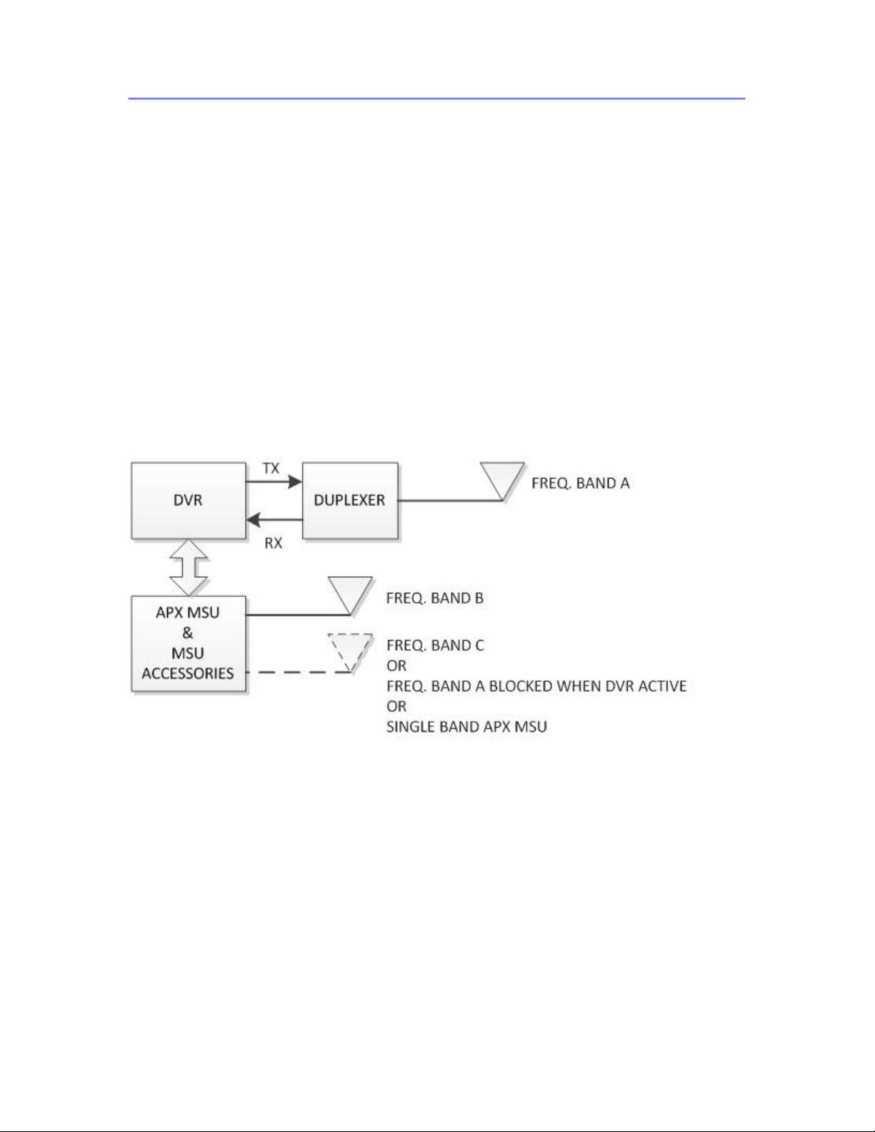
In dual band MSU configuration either the MSU & DVR operate in 3 different frequency
bands or one of the MSU frequency bands is locked out when DVR operation is enabled
as shown on Figure 1.
Figure 1 Cross-Band Full Duplex & Simplex Capable DVRS - Conceptual Diagram
The Cross-Band DVRS typically includes a duplexer which can accommodate full duplex
and simplex DVR operation as shown on Figure 1. The cross-band duplexer however
has a limited pass-band window and is tuned to the DVR frequencies provided on the
purchase order.
APX8500 may require interface kit. Please refer to the DVR/VRX1000 Ordering Guide.
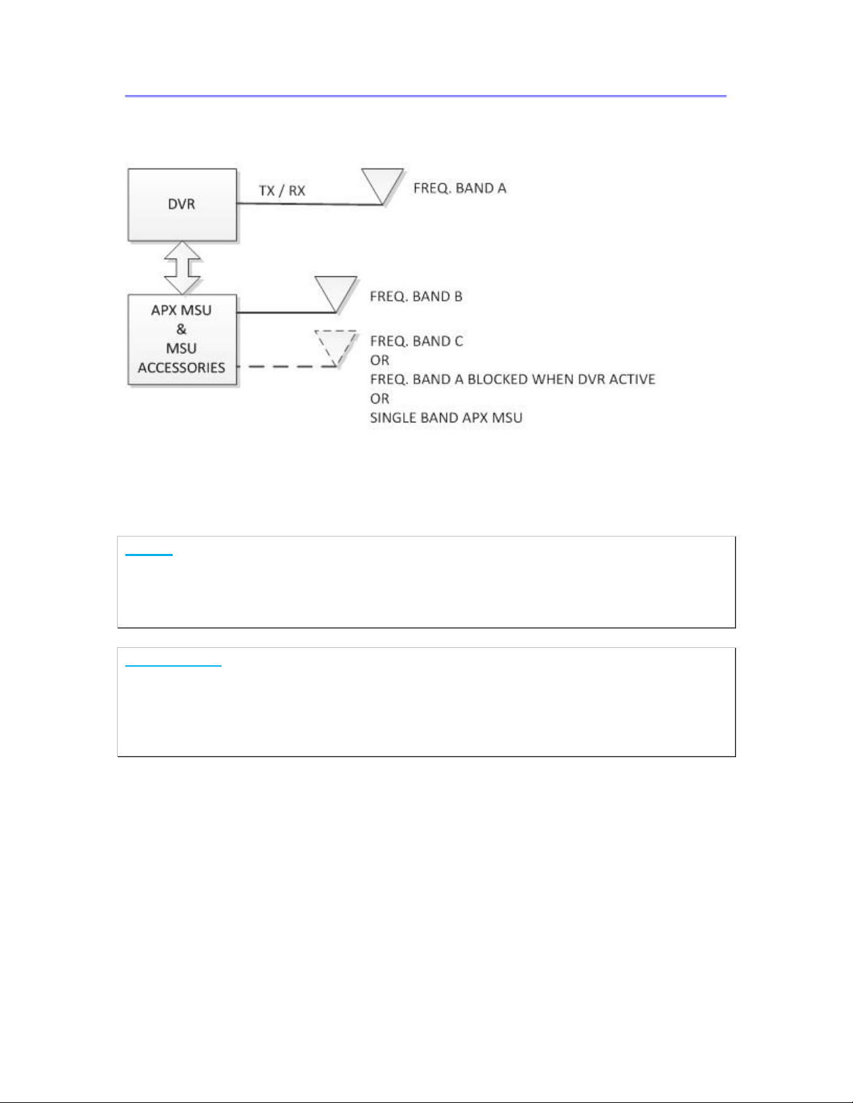
As an option, a cross-band DVRS can be configured for simplex only operation as
shown on Figure 2. In this case the DVRS does not utilize any filters.
Page 16
8A083X30 Rev.11
APX Series P25 Interface
DVRS User’s Guide
January 2019 Page 16 of 94
Figure 2 Cross-Band Simplex Only Capable DVRS - Conceptual Diagram
APX8500 may require interface kit. Please refer to the DVR/VRX1000 Ordering Guide.
NOTE:
The vehicular (side-by-side) mount Cross-Band DVR can be interfaced to a High Power
MSU, however, the Transmit power of the MSU must be reduced to comply with the
maximum power restrictions described in the RF Safety Booklet 8F083X03, which is
provided with the DVR.
IMPORTANT!
The DVRS is shipped equipped with custom filters tuned to the specified
frequency range provided by the Customer. Programming the DVR / MSU to
operate on frequencies outside of the original specified bands may result in
intermittent or complete loss of communications. Frequency changes may require
filter retuning or replacement.
Page 17
8A083X30 Rev.11
APX Series P25 Interface
DVRS User’s Guide
January 2019 Page 17 of 94
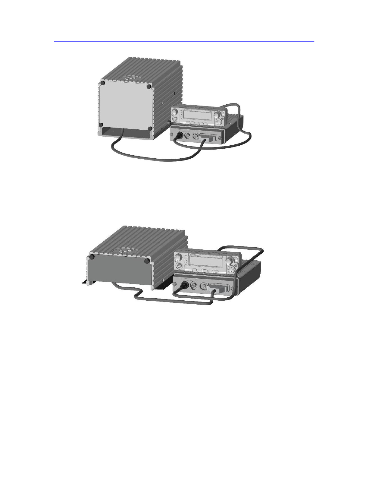
Figure 4 Vehicular Mount Cross Band DVRS Model - Simplex Only Capable
Figure 3 Vehicular Mount Cross Band DVRS Model – Full Duplex & Simplex Capable
Page 18

8A083X30 Rev.11
APX Series P25 Interface
DVRS User’s Guide
January 2019 Page 18 of 94
In-Band
The in-band DVRS models are equipped with two sets of filters, which are required in
order to ensure interference-free operation when both the MSU and DVR are
transmitting and receiving simultaneously in the same frequency band. The DVR is a full
duplex capable repeater, equipped with a duplexer, which provides sufficient isolation to
prevent desense during DVR repeat activation. The DVR duplexer also provides 40 dB
isolation on the Mobile radio transmit / receive frequencies. The filters installed at the
output of the MSU are designed to provide 40 dB isolation on the DVR transmit and
receive frequencies.
IMPORTANT!
The above filtering isolation must be complemented by 30dB minimum antenna
isolation (between the DVR and Mobile Radio antennas) in order to ensure
interference-free operation. It is recommended that the Mobile antenna is mounted
on the roof of the vehicle while the DVR antenna is mounted on the trunk.
Each DVRS is equipped with custom filters tuned to the specified frequency
bands – note the frequency range specified on the filter Labels.
Programming the DVR / Mobile radio to operate on frequencies outside of the
original specified bands may result in intermittent or complete loss of
communications. Frequency changes may require filter retuning or replacement.
The in-band DVRS models are also equipped with an RF bypass switch, which
bypasses the filtering at the output of the MSU when a “DVR – Disabled” TG is selected
on the MSU control head (see Figure 5).
When a “DVR – Enabled” TG is selected on the MSU CH, the RF switch automatically
connects the extra filters between the MSU antenna port and the MSU antenna to
ensure interference-free operation.
The complex in-band filtering is only feasible if sufficient frequency gap is present
between the DVR frequencies and the MSU frequencies associated with the “DVR -
Enabled” TGs.
For more information on the feasible filtering options, please refer to the DVRS Ordering
Guides.
As an option, an in-band DVRS can also be configured as simplex only (Figure 6). The
simplex in-band configuration however still requires DVR and in-band filters.
NOTE:
The DVR and MSU always require two (or three in the case of dual band MSU) separate
antennas.
NOTE:
The In-Band filters connected to the MSU have typical insertion loss of 1.5dB.
Page 19
8A083X30 Rev.11
APX Series P25 Interface
DVRS User’s Guide
January 2019 Page 19 of 94
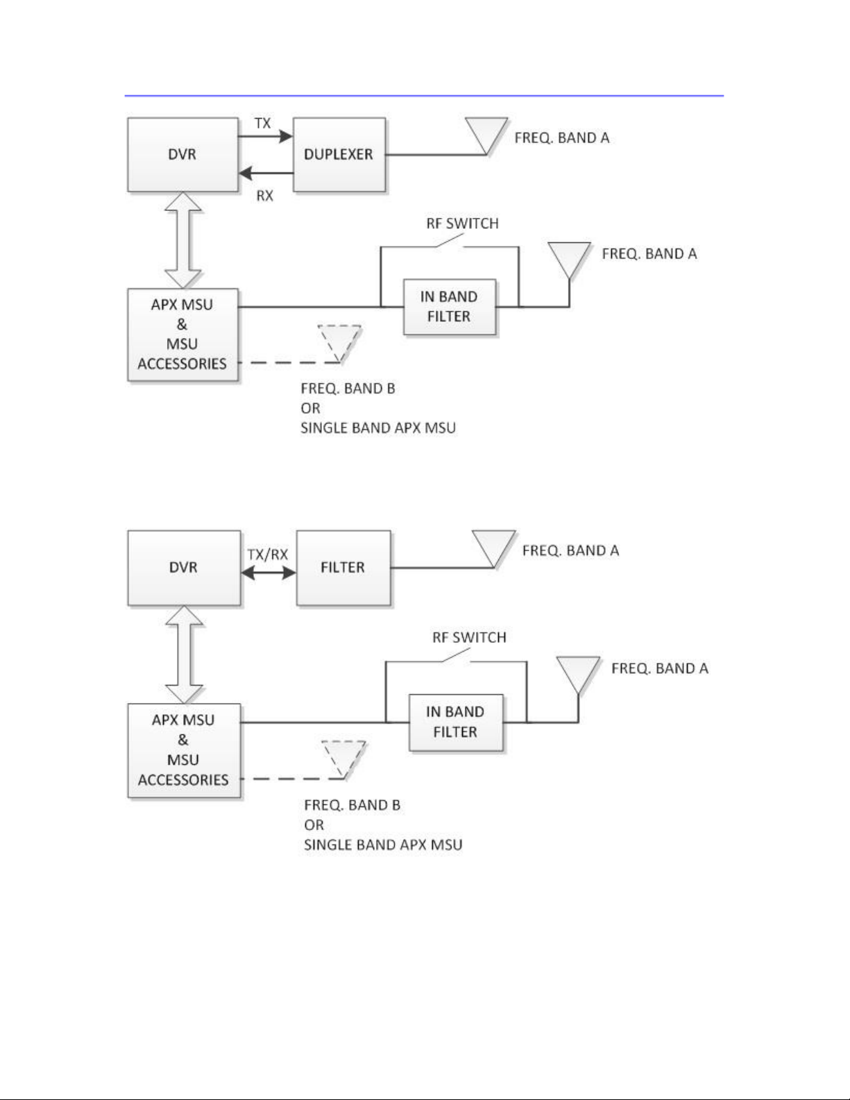
Figure 5 In-Band Full Duplex / Simplex Capable DVRS - Conceptual Diagram
Figure 6 In-Band Simplex Only Capable DVRS - Conceptual Diagram
Page 20
8A083X30 Rev.11
APX Series P25 Interface
DVRS User’s Guide
January 2019 Page 20 of 94
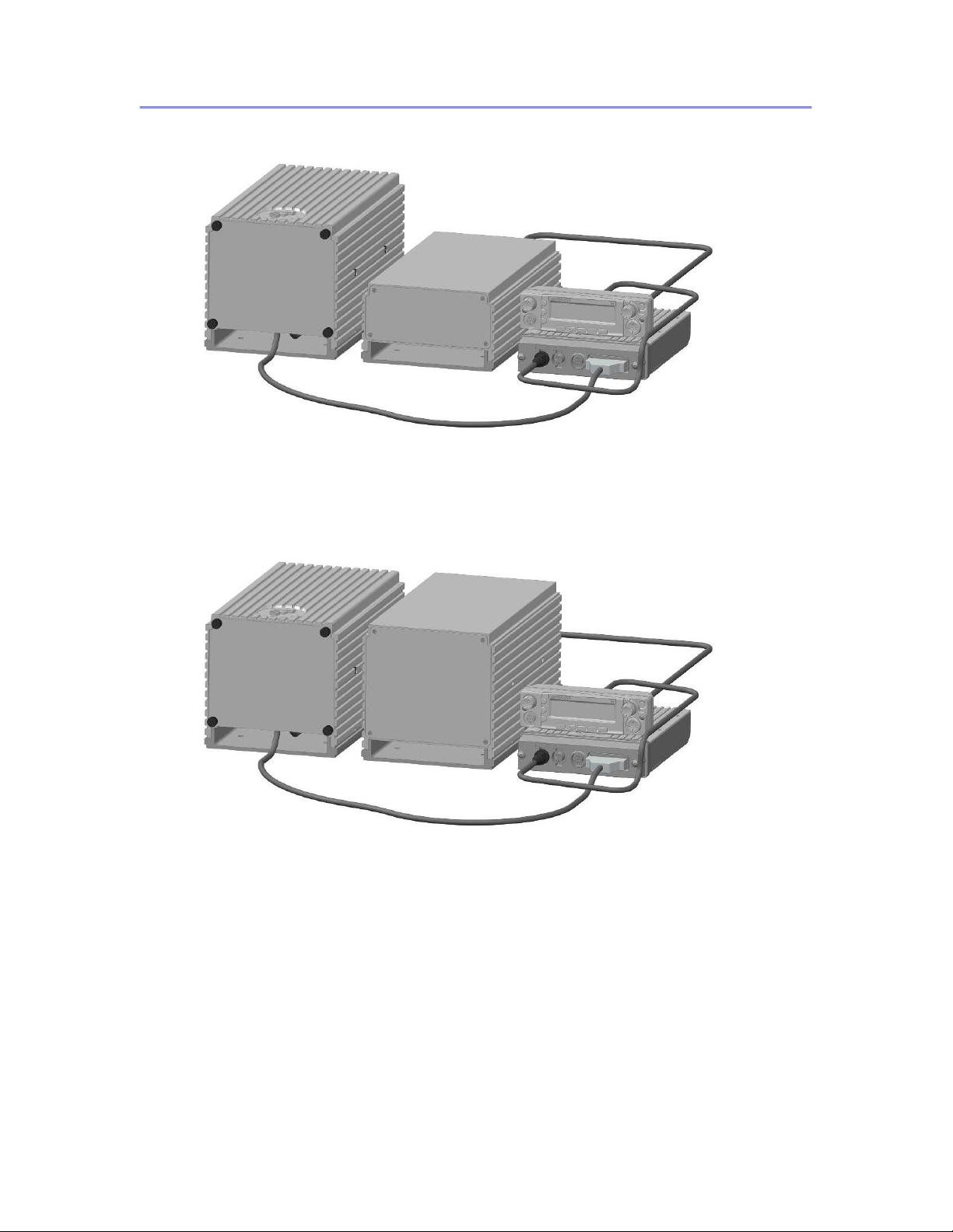
Figure 7 Vehicular Mount In-Band 700 or 800MHz DVRS Model - Full Duplex & Simplex
Capable
Figure 8 Vehicular Mount In-Band VHF or UHF DVRS Model - Full Duplex & Simplex
Capable
Page 21

8A083X30 Rev.11
APX Series P25 Interface
DVRS User’s Guide
January 2019 Page 21 of 94
Band Locking
When both the MSU and DVR are configured to operate in the same frequency band,
the DVRS requires a special set of filters including and in-band filter placed at the MSU
antenna port. The special in-band filters are required in order to prevent interference
when the DVR and MSU are activated at the same time. When the in-band filter is not
present (‘MSU RF Bypass switch’ in the Tweaker Hardware setup screen is unchecked),
the Band Lock feature is enabled by default and the Tweaker prevents DVR operation
on MSU channels that are explicitly using the same frequency band as the DVR. On
MSU channels where the frequency band is not explicitly known such as in multi-site
Trunking systems, the MSU will be prevented from using frequencies in the same band
while the DVR is active (i.e. in SYSTEM or LOCAL mode). In this case the MSU will no
longer allow roaming to sites using the locked out band. If the MSU is currently on a
Trunking site that uses the locked out band, the MSU will roam to another site. If no
other sites are available, the MSU will become Out Of Range. When the DVR is inactive
(OFF mode), the MSU frequency band is unlocked.
If Band Locking is disabled in the Tweaker, the MSU is allowed to roam to any site
regardless of the frequency band. A typical in-band application that may require Band
Locking to be disabled is the Fixed DVRS application when the MSU and DVR antennas
are mounted in such way as to provide minimum 70dB of isolation and in-band filtering is
not required.
For MSU conventional channels where the band is known and fixed, the DVR restricts
access to channels using the locked out frequency band.
If Band locking is enabled in the DVR and SCAN is enabled in the MSU, the MSU will
skip over any channels in the scan list that are configured to operate in the same
frequency band as the DVR.
For information on MSU Scan operation and limitations, please refer to the MSU Scan
section of this document.
Page 22

8A083X30 Rev.11
APX Series P25 Interface
DVRS User’s Guide
January 2019 Page 22 of 94
Suitcase Mount DVRS
The DVRS is packaged in a durable suitcase and includes all necessary electronics and
filtering. The unit can be easily deployed in the field and is powered up either by
plugging into an AC outlet or by using an optional battery backup kit. The battery backup
kit is also packaged in a suitcase for ease of transportation.
The Suitcase model requires two or three antennas – one or two connected to the MSU
and one to the DVR. The MSU antenna needs to be strategically deployed in order to
ensure reliable link between the MSU and the radio system infrastructure. The DVR
antenna needs to be positioned to provide optimum radio coverage for the portable radio
users.
Cabinet Mount DVRS
This DVRS model is housed in a wall-mount indoor enclosure and includes all necessary
electronics and filtering. The Cabinet Mount DVRS is intended for permanent i.e. ‘Fixed’
type installations.
Cabinet Mount DVRS Suitcase Mount DVRS Battery Pack P25 Tactical Repeater
for TDVRS with backpack option
The indoor cabinet mount DVRS models can be upgraded to outdoor enclosure by
adding option TT05130AA as described in the DVRS Ordering Guide.
P25 Tactical Repeater with Backpack option
The P25 Tactical Repeater comes in a Backpack Frame (optional) designed for comfort
and stability.
When used as a Tactical Repeater, the full duplex DVR provides extended portable-toportable radio capabilities by receiving the analog or digital signals sent by a portable
radio and retransmitting them to the other portable radios in the area
Page 23

8A083X30 Rev.11
APX Series P25 Interface
DVRS User’s Guide
January 2019 Page 23 of 94
DVRS Operation Basics
The operation of the DVRS is determined by the following:
• Firmware options and programming settings of the DVR (DVR personality).
• Firmware options and programming settings of the APX MSU interfaced to the
DVR.
• Configuration capabilities and programmed settings of the radio system.
• Type and programming settings of the portable radios used for communications
through the DVR.
IMPORTANT!
Depending on the selected personality settings and configuration capabilities of
the complete radio system infrastructure, the features / options described
throughout this document may or may not be applicable to the specific DVRS
operation.
Page 24

8A083X30 Rev.11
APX Series P25 Interface
DVRS User’s Guide
January 2019 Page 24 of 94
DVRS Features by PSU Type – Motorola Infrastructure
When the PSU user is out of system radio coverage, the PSU can be switched to a
dedicated DVR channel so that the PSU can communicate via the DVRS. The features
available to the PSU user depend on the PSU type, programming and selected mode.
The table below specifies what features are supported by the different PSU types.
PSU FEATURE SUPPORT BY
DVRS
DVRS Enabled
PSU [Note 5]
Generic
P25 PSU
Analog PSU
Registration / Deregistration
Yes
Yes [Note 1]
Yes [Note 3]
Talk Group Proxying / Translation
Yes
Yes
No
Group Calls
Yes
Yes
Yes
PSU PTT ID
Yes
Yes
Yes [Note 2]
Private Calls
Yes
No
No
Announcement Group
No
No
No
Phone Interconnect
Yes
No
No
Patch
Yes
No
No
Dynamic Regrouping
Yes
No
No
Selector Lock / Unlock
No
No
No
Emergency Call / Alarm
Yes
Yes
Yes
Emergency ID Pass Through
Yes
Yes
Yes [Note 2]
PSU Hot Mic
Yes [Note 4]
No
No
PSU Emergency Revert
Yes
Yes
Yes
P25 Encryption
Yes
Yes
No
Call Alert /Page
Yes
Yes
No
System Status Broadcast (Failsoft,
Out Of Range, Site Trunking)
Yes
No
No
Local Mode Indication
Yes
No
No
Automatic Revert to TA when no
DVR
Yes
No
No
Adaptive Power Control
Programmable
Yes [Note 6]
No
Talk Permit Tones (generated by
PSU)
Yes
No
No
Leading / Trailing Tones (sent over
the air)
No
No
Yes
Radio Check / Radio Inhibit
Yes
Yes
No
P25 Trunking OTAR
Yes
No
No
PSU Group Services
Yes [Note 7]
No
No
PSU LOCATION
Yes
No
No
PSU SCAN
No
No
No
Remote DVR Activation by PSU
Yes (Call Alert)
Yes (Call Alert)
Yes (DTMF)
Remote DVR Activation by PSU
Emergency Alarm
Yes
Yes
Yes
(MDC1200)
End to End digital on TDMA P25
Phase 2
Yes[Note 8]
No
No
Table 2 DVRS Features vs Type of PSU
Note 1 When selecting a DVR Mode on the Generic P25 PSU, it registers upon first Group Call. Generic
PSU is deregistered after a preprogrammed timer counting the period of inactivity expires.
Note 2 Supported only with MDC1200 capable portables.
Note 3 Analog PSU is registered on the P25 system with its MDC1200 ID.
Note 4 Requires firmware R12.00.13 or later in the XTS ‘DVRS Enabled’ PSU and R07.00.05 or later if
using APX ‘DVRS/VRX Enabled’ PSU.
Note 5 The PSU models that can be programmed as DVRS Enabled are described in Table 6.
Page 25

8A083X30 Rev.11
APX Series P25 Interface
DVRS User’s Guide
January 2019 Page 25 of 94
Note 6: Motorola Solutions XTS or APX series PSUs in non DVRS/VRX Enabled mode.
Note 7: Group services only supported on APX ‘DVRS Enabled’ PSUs (R14.50.00 or later in PSU/MSU).
‘DVRS Enabled’ PSU Features Support in Non-Motorola
Infrastructure
‘DVRS ENABLED’ PSU FEATURE SUPPORT
HARRIS
P25 Trunked FDMA
CASSIDIAN
P25 Trunked FDMA
PSU Registration / Deregistration
Yes
Yes
PSU Talk Group Proxying / Translation
Yes
Yes
In Car Monitor
Yes
Yes
MSU MIC PTT with DVRS ON
Yes
Yes
PSU Group Calls
Yes
Yes
PSU PTT ID
Yes
Yes
PSU Private Call II *
Yes
Yes
PSU Emergency Call / Alarm
Yes
Yes
PSU Emergency ID Pass Through
Yes
Yes
PSU Hot Mic
Yes
Yes
PSU P25 Encryption
Yes
Yes
PSU Call Alert Page
Yes
Yes
Out Of Range / Site Trunking indication on PSU
Yes
Yes
DVRS OOR indication on PSU
Yes
Yes
FNE NO COMMS indication through DVRS
Yes
Yes
DVRS Local Mode Indication on PSU
Yes
Yes
Talk Permit Tones (generated by PSU)
Yes
Yes
PSU Radio Check / Radio Inhibit
Yes
Yes
PSU P25 Trunking OTAR
Yes - Limited
Yes
PSU Adaptive Power Control
Yes
Yes
PSU Phone Interconnect
Yes
Yes
PSU Patch & Simulselect
Yes
Yes
PSU Dynamic Regrouping
Not Supported
Not Supported
Automatic Revert to TA when no DVR
Yes
Yes
PSU LOCATION
Yes
Yes
Remote DVR Activation by PSU Call Alert Page
to DVR ID
Yes
Yes
Remote DVR Activation by PSU Emergency
Alarm Retries
Yes
Yes
PSU Status / Message
Yes
Yes
Remote MSU Channel Steering via PSU Call
Alert Page to DVR ID
Yes
Yes
Data
Not Supported
Not Supported
PSU OTAP
Not Supported
Not Supported
MSU Votescan
Not Supported
Not Supported
Limited Features support on P25 TDMA FNE
Yes
(Group Voice, PTT-ID
and Emerg Alarm/Call)
Not Supported
Table 3 'DVRS Enabled' PSU Features Support on Non-MSI Infrastructure
*PC II Support only; Enhanced Private Calls are only supported on Motorola Infrastructure.
Page 26

8A083X30 Rev.11
APX Series P25 Interface
DVRS User’s Guide
January 2019 Page 26 of 94
Powering up the DVRS
The DVR powers up together with the MSU. The power up mode and channel are
programmable. Depending on the programmed personality, the DVR can power up in
one of the following states:
• DVR Disabled mode, last selected DVR channel
• OFF mode
• SYSTEM mode, last selected DVR channel
• SYSTEM mode, preprogrammed DVR channel
• LOCAL mode, last selected DVR channel
• LOCAL mode, preprogrammed DVR channel
• If the DVRS powers up on a ‘strapped’ mobile radio channel, the DVR will be
steered according to the Talk Group selected on the MSU. The steering may
involve both DVR channel and mode change.
Turning ON the DVRS
When the MSU is powered up, the DVRS can be activated by one or more of the
methods described in the following section.
• The DVR is ON when SYSTEM (or optionally LOCAL) mode of operation is
selected.
• The DVR is OFF when OFF mode is selected.
• The DVR is disabled when a “DVR Disabled” Mode / Channel is selected on the
APX MSU or if the currently selected DVR and MSU modes are incompatible
(such as TDMA MSU mode and P25 Digital DVR channel).
NOTE:
The DVR can only be activated when a compatible “DVR Enabled” mode / channel is
selected on the APX MSU.
Activating the DVRS via the Control Head
Ensure the MSU is powered up and a DVR Enabled TG / channel is selected on the
control head.
To activate the DVR:
• Press the DVRS menu item to enter the ‘DVR Control Mode’.
• Once in the ‘DVR Control Mode’ screen, press the MODE button to toggle the
available DVR modes until the desired mode is selected.
• Press the SEL button or wait 6 seconds until the ‘DVR control Mode’ screen
times out. The last selected DVR mode becomes effective.
Pressing the DVRS button allows the user to enter the ‘DVR Control Mode’ and to select
the desired DVR mode and DVR channel as described in the
Page 27

8A083X30 Rev.11
APX Series P25 Interface
DVRS User’s Guide
January 2019 Page 27 of 94
Automatic DVRS Activation (AVRA)
The DVR can be activated automatically (switched from OFF or LOCAL to SYSTEM
Mode) if one of the VIP inputs on the MSU control head is wired to the desired trigger
source – portable charger switch or door switch or custom manual switch.
When AVRA is enabled in the DVR, the user still has the option of manually changing
the DVR mode from the MSU control head or remotely.
The AVRA feature depends on the DVR programming as shown below:
AVRA Configuration
(as programmed in DVR)
System Mode
Allowed
VIP Input
Current DVR
Mode
New DVR mode
Activation / Deactivation
True
Asserted
OFF
SYSTEM
Activation / Deactivation
False
Asserted
OFF
LOCAL
Activation / Deactivation
True
Asserted
LOCAL
SYSTEM
Activation / Deactivation
False
Asserted
LOCAL
LOCAL
Activation / Deactivation
True
Asserted
SYSTEM
SYSTEM
Activation / Deactivation
True/False
De-asserted
ANY
OFF
Activation Only
True
Asserted
OFF
SYSTEM
Activation Only
False
Asserted
OFF
LOCAL
Activation Only
True
Asserted
LOCAL
SYSTEM
Activation Only
False
Asserted
LOCAL
LOCAL
Activation Only
True
Asserted
SYSTEM
SYSTEM
Activation Only
True/False
De-asserted
ANY
NO CHANGE
Toggle
True
Asserted
OFF
SYSTEM
Toggle
False
Asserted
OFF
LOCAL
Toggle
True/False
Asserted
LOCAL
OFF
Toggle
True
Asserted
SYSTEM
OFF
Toggle
True/False
De-asserted
ANY
NO CHANGE
Table 4 AVRA Functionality
Page 28

8A083X30 Rev.11
APX Series P25 Interface
DVRS User’s Guide
January 2019 Page 28 of 94
Remote Activation of the DVRS
Via Call Alert (Page) to DVR
NOTE:
This feature requires the use of a P25 PSU and implies Digital or Forced Analog DVRS
mode of operation.
To remotely activate a DVR, the PSU user can send a Call Alert (Page) with the ID of
the specific DVR.
Upon receipt of a Call Alert (Page) from the PSU the DVR will:
• Switch from OFF or LOCAL mode to SYSTEM mode (unless it is already in the
SYSTEM mode). If the selected DVR / MSU channel is programmed as LOCAL
only, the DVR will switch from OFF to LOCAL mode.
• Switch to Primary status and force any other Primary DVR to become a
Secondary unless there is a Permanent Primary (on the same DVR channel)
already present in the same area.
• Force the MSU to revert to a TG selected on the PSU (if programmed).
Via PSU Emergency Alarm
The DVR switches from OFF to SYSTEM mode after a programmable number of
Emergency Alarm attempts sent by a PSU are successfully received by the DVR and are
not serviced by another (Primary) DVRS.
Via PSU DTMF Tones
To remotely activate a DVR (analog mode), the PSU user can send a preprogrammed
DTMF sequence, which can be received by DVRS in the PSU radio coverage area.
Upon receipt of the preprogrammed DTMF sequence from the PSU the DVR will:
• Switch from OFF or LOCAL mode to SYSTEM mode.
• Switch to Primary status unless there is already a Primary / Permanent Primary
DVRS (on the same DVR channel) already present in the same area.
DTMF activation is supported on analog or mixed mode DVR channels only.
Page 29

8A083X30 Rev.11
APX Series P25 Interface
DVRS User’s Guide
January 2019 Page 29 of 94
Via System / Dispatcher Call Alert Page to MSU
Dispatcher can send a Call Alert (Page) to a specific MSU ID, which in turn causes DVR
mode change in the following order: OFF-SYS-LOC-OFF.
The MSU can be programmed to support one of the following configurations:
a. Call Alert / Remote Activation Disabled – the MSU does not respond to any Call
Alert requests
b. Call Alert Enabled – the MSU responds to Call Alerts addressed to its ID and
does NOT initiate DVRS mode change
c. Remote Activation Enabled – the MSU will acknowledge Call Alerts addressed to
its ID and will initiate DVR mode change provided the source ID of the Call Alert
is programmed in the “DVR Remote Activation IDs” table.
If “Generate Status on DVR Mode Change” is enabled for a given DVRS Profile (in the
APX MSU) , the MSU will send back a mode change status to indicate the current DVRS
mode (OFF, SYSTEM, LOCAL). Only the dispatcher console can interpret those status
messages:
DVR MODE
STATUS VALUE
OFF
1
LOCAL
2
SYSTEM
3
Dispatcher can’t force a Non-Primary DVR to become a Primary and can’t activate a
DVR when a ‘VR Disabled’ mode is selected on the control head.
Page 30

8A083X30 Rev.11
APX Series P25 Interface
DVRS User’s Guide
January 2019 Page 30 of 94
Turning OFF the DVRS
Deactivating the DVRS via the MSU Control Head
To deactivate the DVR via the MSU control head:
• Press the DVRS button to enter the ‘DVR Control Mode’, then press the MODE
button until VR OFF is displayed and either press the SEL button or wait for the
screen timeout (6 seconds).
OR
• Select a ‘DVR Disabled’ TG / Mode / Zone on the MSU
OR
• Power down the MSU if radio operation is no longer required.
Deactivating the DVRS via Call Alert sent by Dispatch
Dispatcher can send a Call Alert (Page) to a specific MSU ID, which in turn causes DVR
mode change in the following order: OFF-SYS-LOC-OFF.
The MSU can be programmed to support one of the following configurations:
a. Call Alert / Remote Activation Disabled – the MSU does not respond to any Call
Alert requests
b. Call Alert Enabled – the MSU responds to Call Alerts addressed to its ID and
does NOT initiate DVRS mode change
c. Remote Activation Enabled – the MSU will acknowledge Call Alerts addressed to
its ID and will initiate DVR mode change provided the source ID of the Call Alert
is programmed in the “DVR Remote Activation IDs” table.
If “Generate Status on DVR Mode Change” is enabled for a given DVRS Profile (in the
APX MSU) , the MSU will send back a mode change status to indicate the current DVRS
mode (OFF, SYSTEM, LOCAL). Only the dispatcher console can interpret those status
messages:
DVR MODE
STATUS VALUE
OFF
1
LOCAL
2
SYSTEM
3
Dispatcher can’t force a Non-Primary DVR to become a Primary and can’t activate a
DVR when a ‘VR Disabled’ mode is selected on the control head.
Page 31

8A083X30 Rev.11
APX Series P25 Interface
DVRS User’s Guide
January 2019 Page 31 of 94
Automatic DVRS Deactivation
AVRA
If the DVR is in the SYSTEM or LOCAL Mode and the AVRA VIP input is de-asserted,
the DVR can be programmed to automatically switch to OFF Mode as described in
Table 4. If the DVR is in the OFF Mode, de-asserting the AVRA VIP will not result in any
change. The method of de-asserting the AVRA VIP depends on the actual installed
AVRA trigger. For example, if the selected AVRA trigger is the Portable Charger Switch,
de-asserting the AVRA VIP input is equivalent to placing the PSU back in the charger.
Inactivity Timer
If programmed, the DVR can switch automatically to OFF mode upon expiration of its
Inactivity Timer (programmable from 0 to 180 minutes). The timer is restarted every time
the DVR detects PSU activity.
Page 32

8A083X30 Rev.11
APX Series P25 Interface
DVRS User’s Guide
January 2019 Page 32 of 94
DVRS Status Display
The following MSU control head display Icons / messages relate to the DVRS operation:
O5 DISPLAY ICON /
MESSAGE
DVRS STATUS DESCRIPTION
Steady
V R
DVR is in a Primary State
Steady
Primary DVR Receiving
Steady
Primary DVR Transmitting
Steady
Primary DVR Receiving and Transmitting
Flashing
V R
DVR is in a Secondary State
Flashing
Secondary DVR Receiving
Steady
V R
DVR is in a Permanent Primary State
Flashing
V R
DVR is in a Permanent Primary on Standby (there is
another Permanent Primary already present in the area)
Flashing
Permanent Primary on Standby Receiving
Steady
Permanent Primary Receiving
Steady
Permanent Primary Transmitting
Steady
Permanent Primary Receiving and Transmitting
VR SERVICE
DVR is in Service Mode (during re-flashing of the
firmware).
VR ERROR
DVR detected error. Display toggles between VR ERROR
and the actual error code / number.
VR IN RESET
DVR is being reset
VR DISABLED
DVR Disabled on selected MSU TG / Mode
Table 5 DVRS Status Display Messages / Icons
Page 33

8A083X30 Rev.11
APX Series P25 Interface
DVRS User’s Guide
January 2019 Page 33 of 94
DVRS Enabled PSUs
The following Portable Radios have firmware that allows enhanced communications with
the DVR and support of an extended list of features.
PSU Models that can be ‘DVRS
Enabled’
PSU Firmware Revision Required
XTS1500
XTS2500
XTS5000
R9.00.00 and higher
Note: It is highly recommended to always use the latest
released PSU firmware to ensure all fixes and new features
are included.
APX4000
APX6000
APX7000
APX8000
R17.01.00 and higher
Note: It is highly recommended to always use the latest
released PSU firmware to ensure all fixes and new features
are included.
APX portable radios operating through a DVR,
utilizing the enhanced DVR digital feature set
require subscriber option QA00631.
Table 6 DVRS Enabled PSU Models
All other P25 capable PSU models or the above models with either older firmware
versions or when not programmed as ‘DVRS Enabled’, can only be programmed as ‘P25
Generic’ since they are not capable of extended communications with the DVR.
Page 34

8A083X30 Rev.11
APX Series P25 Interface
DVRS User’s Guide
January 2019 Page 34 of 94
DVRS Status Tones
DVRS Status Tones - MSU Speaker
The following DVRS specific tones will be heard in the MSU speaker under the
circumstances described below:
TONE TYPE
TONE NAME
DVRS STATUS
Short high-pitched tone
DVRS Button Press
Indicates a valid DVRS Button
press during DVRS Selection
Mode.
Short low-pitched tone
DVR Invalid Option
Indicates Invalid DVR selection
(for example when pressing the
PM button when PM option is
disabled).
Long high-pitched tone
DVR Control
Timeout
Indicates the end of DVR Control
Mode session. The last DVR
settings (DVR channel, DVR
mode, Permanent Primary status)
selected by the user and displayed
on the MSU control head become
active.
Chirping Sound
Permanent Primary
ON/OFF
Indicates Permanent Primary
ON/OFF.
Two short low-pitched
tones
50% Transmit Duty
Cycle
Indicates that the DVR and Mobile
radio transmitters have been
keyed up more than 50% of the
time over the past 30 minutes and
any nearby bystanders may be
getting excessive RF radiation.
The users must immediately limit
their talk time to comply with FCC
rules.
Single high-pitched tone
every few seconds (5-255
sec. programmable)
DVR Active
Indicates the DVR is either in
SYSTEM or LOCAL mode
(programmable). The ‘DVR Active’
tones are heard in both Primary
and Secondary DVR modes.
Table 7 DVRS Status Tones (MSU Speaker)
Page 35

8A083X30 Rev.11
APX Series P25 Interface
DVRS User’s Guide
January 2019 Page 35 of 94
DVRS Status Tones - PSU
P25 ‘DVRS Enabled’ PSU
The following DVRS-only specific tones are available (if programmed) in the P25 PSU:
TONE TYPE
TONE NAME
DESCRIPTION
Series of short beeps
Go Ahead
System (clear)
DVRS system mode talk permit tone, clear
voice
Series of short beeps
Go Ahead
System (secure)
DVRS system mode talk permit tone,
encrypted (secure) voice
Series of short beeps
Go Ahead Local
(clear)
DVRS local mode talk permit tone, clear
voice
Series of short beeps
Go Ahead Local
(secure)
DVRS local mode talk permit tone,
encrypted (secure) voice
Low pitched tone
every 30 seconds
Low Car Battery
Sent by the DVRS when the car battery
voltage is below the programmed threshold
Series of short beeps
Queued Call
Call has been queued, waiting for system
grant
Two short beeps
No Activity
Timer Expiration
Warning tones sent to alert the PSU users
that the DVR will switch from SYS/LOC to
OFF. Sent every minute for the last 5
minutes prior to the switching.
Three beeps
DVR Active
Tones sent upon DVRS activation (SYS or
LOC mode).
Table 8 P25 DVRS Enabled PSUs – DVRS Specific Tones
Generic P25 PSUs
‘Low Car Battery’, ‘No Activity Timer Expiration’ and ‘DVR Active’ tones (as described in
Table 8 above) are supported.
Page 36

8A083X30 Rev.11
APX Series P25 Interface
DVRS User’s Guide
January 2019 Page 36 of 94
Conventional Analog PSUs
The DVR in analog mode can be configured to send the following tones to the analog
PSUs:
TONE TYPE
TONE NAME
DESCRIPTION
Beep
Encrypted
Call
Sent to local analog PSUs when the MSU is
receiving encrypted call. The beeps are sent until
the encrypted call ends.
Three Short Beeps
Long Low pitched
tone
Leading Go
Ahead
Leading
Deny
Leading tones sent by the DVR over the air upon
receipt of system grant. Requires the LPSU user
to do ‘double PTT’ in order to get a channel and
release the PTT to be able to receive the Leading
Tones.
Single high-pitched
tone
Longer Low pitched
tone
Trailing
Successful
System
Access
Trailing
Unsuccessful
System
Access
Trailing Tones sent by DVR in analog mode to
conventional analog PSUs at the end of PSU
transmission. If the transmission was
unsuccessful the PSU User will know that he /
she needs to repeat the message if they want to
reach the system. Lack of Trailing tones would
indicate that the PSU user is outside of the DVR
range.
Single Low pitched
tone every 30
seconds
Low Battery
The Low Battery tones are sent to the local
portables every 30 seconds when the battery
voltage drops below the programmed threshold.
Single Low pitched
tone
Trailing Access
Denied
Indicates system was busy and the portable radio
call was only repeated locally.
Programmable or
default (3 short
beeps)
Emergency
ACK
If programmed, emergency ACK tones are sent
by the DVR when processing MDC1200
emergency issued by a PSU.
Two short beeps
No Activity
Timer
Expiration
Warning tones sent to alert the PSU users that
the DVR will switch from SYS/LOC to OFF. Sent
every minute for the last 5 minutes prior to the
switching.
Programmable
number of tones,
tone duration and
frequencies.
DVR
Activation
If programmed, DVR generated tones are sent to
the PSUs every time the DVR is activated i.e.
switched to LOCAL or SYSTEM Mode.
Table 9 Analog PSU - DVRS Specific Tones
NOTE:
All PSUs which are in the analog mode DVR radio coverage area and switched to the
DVR channel will hear the DVR status tones since those are transmitted over the air (on
the same frequency with PL/DPL) and are NOT generated by the portable radios.
Page 37

8A083X30 Rev.11
APX Series P25 Interface
DVRS User’s Guide
January 2019 Page 37 of 94
‘DVRS Enabled’ Mobile Radio TGs / Channels
DVR operation may be enabled (by the DVR and MSU programming) on selected mobile
radio Talk Groups / channels and disabled on others.
When the user selects a DVRS Enabled TG / channel on the MSU control head, the
DVR operation is enabled in the following manner:
• The DVR automatically enters the pre-programmed DVR mode/channel
associated (‘Strapped’) with the selected MSU TG / channel if DVR strapping is
programmed in the DVR.
OR
• The user may change the DVR mode / channel (if ‘strapping’ is not enabled) by
pressing the assigned DVRS button and entering the ‘DVR control mode’.
• The DVR can be activated and used to repeat messages between the system
users of the TG/channel selected on the MSU and the PSU users on the
selected DVR channel.
• If enabled in the DVR personality, ‘DVR Enabled’ tones will be heard every few
seconds (5-255 sec. programmable) in the MSU speaker, regardless of the
Primary / Secondary status.
‘DVRS Disabled’ Mobile Radio TGs / Channels
DVR operation may be enabled on selected mobile radio Talk Groups / channels and
disabled on others.
When the user selects a “DVRS Disabled” TG / channel on the control head:
• Pressing the DVRS button results in a DVR Invalid Option Tone (single lowpitched tone).
• DVR operation is prohibited i.e. all DVR functions are disabled.
• Call Alert Page from the local PSU, sent on the last used DVR channel, can steer
the MSU to a ‘VR Enabled’ mode if programmed accordingly.
Page 38

8A083X30 Rev.11
APX Series P25 Interface
DVRS User’s Guide
January 2019 Page 38 of 94
In Car Monitor (ICM)
The ICM feature allows the MSU to monitor PSU Voice traffic and is configurable in the
MSU codeplug as follows:
• ICM is enabled / disabled globally in the MSU via the ‘ICM Allowed’ Field
• If ‘ICM Allowed’ is programmed in the MSU then ICM operation is further
configured on a per MSU channel basis via the ‘ICM Allowed’ codeplug field.
• ICM functionality is further configured to be triggered by either Hang Up Box
(HUB) on / off transitions OR via menu item / button on the MSU control head or
keypad microphone.
When ICM functionality is configured to be triggered via HUB on/off then ‘ICM Selected’
operation takes place when the MSU microphone is placed on HUB, ‘ICM All’ operation
will take place when the MSU microphone is taken off HUB.
For details on how to program the ICM functionality and options in the MSU, please refer
to the corresponding Motorola Documentation.
When the MSU is operating on a Trunking FNE with ICM enabled the following
configurations are available:
• ‘ICM Selected’ – the MSU speaker unmutes to PSU audio matching its selected
TG ID (digital DVR channel) or all qualified analog PSU audio (analog DVR
channel).
• ‘ICM All’ – the MSU speaker unmutes to all PSU audio regardless of the TG ID
(digital DVR channel) or all analog PSU audio (analog DVR channel).
When the MSU is operating on a Conventional FNE with ICM enabled the following
configurations are available:
• ‘ICM Selected’ and MSU configured for Selective Squelch – the MSU speaker
will unmute only to PSU audio matching its selected TG (digital DVR channels) or
qualified analog audio (analog DVR channels)
• ‘ICM Selected’ and MSU configured for Normal Squelch – the MSU speaker will
unmute to any PSU TG audio (digital DVR channels) or qualified analog PSU
audio (analog DVR channels).
• ‘ICM All’ – the MSU speaker unmutes to all PSU audio
Page 39

8A083X30 Rev.11
APX Series P25 Interface
DVRS User’s Guide
January 2019 Page 39 of 94
Primary / Secondary Operation Basics
The DVRS has a built-in simulcast prevention mechanism, which prevents more than
one DVRS to transmit on the same frequency, at the same time, in the same location.
NOTE:
The algorithm is intended to operate in stationary, same scene scenarios only. It cannot
be applied to moving vehicles. Moving vehicles must either have the DVRS switched
OFF or ‘VR Disabled’ MSU mode selected.
The DVRs are capable of communicating with each other and negotiating which DVR is
a Primary, i.e. elected to repeat, and which DVRs are on Secondary for as long as there
is a Primary.
The simulcast prevention algorithm has two phases:
• Primary / Secondary Phase
• Busy Lockout Phase
During the ‘Primary / Secondary’ phase, the DVRs exchange P25 messages on their Rx
frequency. When a DVR is activated (switched to System or Local mode), it sends a
query – “Is there a Primary?” If it receives a Primary (or Permanent Primary) ‘Heart
Beat’, then the DVR assumes Secondary state. If no Primary Heart Beat is received, the
DVR becomes the Primary and starts sending ‘Primary Heart Beats’ notifying other
DVRs of its status.
The ‘Secondary’ DVRs monitor any DVR-related activity while in a Standby mode and
execute Primary/Secondary checks periodically.
The ‘Primary’ DVR services any communication requests in the area and
‘communicates’ its status to the other DVRs periodically.
The Busy Lockout phase serves as an added protection by forcing the Primary DVR not
only to periodically communicate with the other DVRs in the area (using its Rx
frequency) but also to check for any activity on its Tx frequency prior to every repeat. In
order to accommodate the dynamically changing “real life” environment, i.e. DVRs
arriving or leaving the scene at random time, DVR channel / mode changes, Permanent
Primary activation, Remote DVR steering, etc., the Primary / Secondary algorithm has
several built-in layers, configurable in the DVR programmed personality.
The ‘Permanent Primary Status Enable’ field (in the Primary/Secondary Setup
Menu) is disabled by default and should be used only in special applications such as at
remote, fixed DVR installations, during testing or by selected public safety personnel.
The Primary / Secondary Status of a DVR is re-evaluated every time one of the following
takes place:
• Change of DVR channel frequency
• Change of DVR mode
• Remote activation of another DVR
• Selecting a DVR Disabled TG / Channel on the MSU
Page 40

8A083X30 Rev.11
APX Series P25 Interface
DVRS User’s Guide
January 2019 Page 40 of 94
• Powering down a DVRS
• Detected presence or absence of another Primary
• User enforced Permanent Primary status
PRIMARY
STANDBY
PERMANENT
PRIMARY
DEFINITION
An active DVR which
has won the voting
selection and has
been selected to
repeat Local PSU or
System
communications.
An active DVR which
was voted off and
forced to stay on
stand-by, without
repeating for as long
as the elected Primary
DVR is servicing the
communication needs
in the area.
An active DVR, which
is forced by the user or
programmed to act as
a Primary. The
Permanent Primary
forces all other DVRs
in the area to assume
Secondary status. If
more than one
Permanent Primary is
available in the same
area, it will go through
higher level voting to
elect one winning
Permanent Primary.
SELECTION
Transparent to the
user selection via
DVRS voting
algorithm.
Transparent to the
user selection via
DVRS voting
algorithm.
Press the DVRS
button to enter the
‘DVR Control Menu’,
then press the PM
button to toggle
Permanent Primary
Status ON and OFF if
such selection is
enabled in the DVRS
personality.
DISPLAY
Steady
V R
Flashing
V R
Steady
V R
Table 10 Primary DVR Definitions
NOTE:
As an option, an external light may be placed on the top of the vehicle, which can be
used to indicate which DVRS is the currently selected Primary.
Page 41

8A083X30 Rev.11
APX Series P25 Interface
DVRS User’s Guide
January 2019 Page 41 of 94
Permanent Primary Activation
If programmed, a DVRS can be forced to be a Permanent Primary from the MSU CH.
NOTE:
If another Permanent Primary is already present, the newly activated Permanent Primary
DVR will force the “old” Permanent Primary to assume Permanent Primary ‘On Standby’
Status. If the Permanent Primary leaves the scene, the Permanent Primary ‘On
Standby’ takes over. If several users try to simultaneously activate several DVRS as
Permanent Primaries, the DVRs will go through voting to ensure only one Permanent
Primary DVR is selected and all other DVRs are forced to become Permanent Primary
‘On Standby’.
Permanent Primary Deactivation
The Permanent Primary status of a DVRS can be switched off from the MSU CH.
Legacy Mobexcom II Voting Compatibility Mode
The voting compatibility mode is applicable to analog DVRS mode only. If Legacy
Mobexcom II Voting Compatibility mode is enabled in the DVR, its voting algorithm is
compatible with older style analog only Mobexcom II VRs. Enabling this feature allows
seamless replacement of old style VRs with the new DVR by supporting the deployment
of both types of units in the same fleet during the transition period.
Page 42

8A083X30 Rev.11
APX Series P25 Interface
DVRS User’s Guide
January 2019 Page 42 of 94
DVRS Modes of Operation
When a “DVRS Enabled” TG / Channel is selected on the APX MSU control head, the
DVR can be switched to one of the following modes – OFF, LOCAL or SYSTEM.
OFF Mode
ACTIVITY
OFF MODE ACTION
Control Head Display
VR OFF <DVR CH Name>
DVRS Button Press
Short high-pitched tone.
DVR Control Mode is accessible.
MSU Receiving from System
DVR does not repeat audio received by
MSU.
MSU Speaker Audio present.
MSU User PTTs the MSU
Microphone
MSU Keys up. DVR does not key up.
PSU Activity on DVR channel
DVRS Transmit Function Disabled i.e.
No DVR repeat. No Speaker Audio.
Table 11 OFF Mode DVRS Basic Operation
SYSTEM Mode
ACTIVITY
SYSTEM MODE ACTION
Control Head Display
VR SYS <DVR CH Name>
DVRS Active Tones
If programmed, a short high-pitched ‘DVR
Enabled’ tone is repeated every few
seconds (5-255 sec. programmable) in the
MSU Speaker regardless of the Primary /
Secondary Status of the DVR.
DVRS Button Press
Short high-pitched tone.
DVR Control Mode is accessible.
MSU User PTTs the MSU
Microphone
Both DVR and MSU key up.
DVR may be programmed not to key up!
MSU Receiving from System
DVR repeats audio received by MSU to
PSU Users on the designated DVR
Channel. Speaker Audio is present.
PSU Activity on DVR channel
PSU audio is repeated locally by DVRS as
well as by the MSU to the System. MSU
Speaker Audio is present if In-Car Monitor
is enabled in the MSU.
Table 12 SYSTEM Mode DVRS Basic Operation
Page 43

8A083X30 Rev.11
APX Series P25 Interface
DVRS User’s Guide
January 2019 Page 43 of 94
NOTE:
If the selected DVR channel attribute is programmed as Simplex, the local voice repeat
DVR function is not available. If proxying and In-Car Monitor are enabled and the TG
selected by the local PSU is different from that selected on the MSU, then Inbound or
Outbound speaker audio will depend on the MSU ICM setting (‘ICM Selected’ or ‘ICM
All’) as well as the ICM trigger as described in the In Car Monitor (ICM) section of this
document.
LOCAL Mode
ACTIVITY
LOCAL MODE ACTION
Control Head Display
VR LOC <DVR CH Name>
DVRS Active Tones
If programmed, a short high-pitched ‘DVR
Enabled’ tone is repeated every few
seconds (5-255 sec. programmable) in the
MSU Speaker regardless of the Primary /
Secondary Status of the DVR.
DVRS Button Press
Short high-pitched tone.
DVR Control Mode is accessible.
MSU Receiving from System
DVR may be programmed to repeat audio
received by MSU to the PSU Users over the
DVR Channel when the DVR is idle.
Speaker Audio is present.
MSU User PTTs the MSU
Microphone
DVR keys up. MSU may or may not key up
depending on MSU programming.
PSU Activity on DVR channel
PSU audio is repeated locally by DVRS.
Speaker Audio is present if In-Car Monitor
is enabled in the MSU.
Table 13 LOCAL Mode DVRS Basic Operation
Page 44

8A083X30 Rev.11
APX Series P25 Interface
DVRS User’s Guide
January 2019 Page 44 of 94
Selecting DVRS Mode
When a ‘DVRS Enabled’ TG / channel is selected on the MSU, the user may enter the
‘DVRS Control Mode’ by pressing the DVRS button on the control head and change the
DVRS mode / channel / status as described below:
Selecting DVRS Mode from the Control Head
To change the DVRS mode:
• Press the DVRS button and observe the MSU enter the ‘DVR Control Mode’.
• Press the MODE button to toggle the DVRS mode until the desired selection
appears on the top line of the control mode display.
• Once the desired mode is displayed press the SEL button or simple wait for the
DVR control mode to timeout (the last selected DVR Mode is in effect).
Strapped DVRS Mode
The DVRS mode and channel may be programmed to be ‘Strapped’ to the specific MSU
TG/Channel.
In this case, selecting a specific MSU TG / channel on the control head would
automatically force the DVR to revert to a pre-programmed DVR mode and/or channel.
For example, selecting a DVR Enabled TG named ‘DISPATCH’ on the MSU may
automatically force the DVR to switch to DVR Channel 1, SYSTEM Mode. If enabled in
the specific DVR personality programming, the DVRS user can still toggle the DVR
mode by pressing the DVRS button and entering the ‘DVR Control Mode’. If mode
change by the user is prohibited in the specific DVRS personality, the user can only
select between the ‘Strapped’ (either LOCAL or SYSTEM) and OFF DVR modes from
the ‘DVR Control Mode’ menu.
Selecting DVRS Channel
When a ‘DVRS Enabled’ TG / Channel is selected on the MSU, the user may enter the
‘DVRS Control Mode’ by pressing the assigned DVRS button on the MSU control head
and then change the DVRS mode / channel / status as described below:
Independent DVRS Channel Change
To change the DVRS channel:
• Press the DVRS button and observe the display changing to the ‘DVR Control
Mode’ screen with the top line displaying the currently selected DVR mode and
channel.
• Use the MSU control head navigation keys to scroll through the available DVR
channels. Once the desired DVR channel is selected, press the SEL button or
wait until the DVR control mode times out.
Strapped DVRS Channel Change
The DVRS mode and channel may be programmed to be strapped to the specific MSU
TG/channel. In this case, selecting a specific MSU TG / channel would automatically
force the DVR to revert to a given DVR channel and/or mode.
For example, selecting a DVR Enabled TG named ‘DISPATCH’ on the O5 may
automatically force the DVR to switch to DVR Channel 1, SYSTEM Mode.
Page 45

8A083X30 Rev.11
APX Series P25 Interface
DVRS User’s Guide
January 2019 Page 45 of 94
When strapping is enabled, and the DVR channel follows the MSU TG/mode selection,
the user may still be allowed (if enabled by the DVR programmed personality) to change
the DVR channel by pressing the DVRS button and then turning the mode knob.
NOTE:
Depending on the specific DVR personality programming, the DVR channel selection
may be restricted to a short list of allowed DVR channels (or no channel selection
options at all). If channel strapping is enabled then the DVR will always land on the
specified strapped DVR channel first even when more than one channels are on its
allowed channels list. For example, when TG named ‘DISPATCH’ is selected on the O5,
the DVR automatically lands on DVR CH 1 and the User may be allowed to toggle
between DVR Channels 1 and 4 while the selection of DVR channels 2 and 3 may be
prohibited.
Page 46

8A083X30 Rev.11
APX Series P25 Interface
DVRS User’s Guide
January 2019 Page 46 of 94
MSU Scan
Supported MSU Scan Types
The MSU Scan feature is allowed while the DVRS is active (System or Local Mode) if
the MSU Scan type is configured as one of the following:
• Trunking Scan
• Conventional Scan
• Mixed Conventional Voting Scan
• Legacy Voting Scan
• Multi System Scan
• Priority Monitoring
The MSU does not support any other modes of scan operation, apart from those listed
above, while the DVRS operates in SYSTEM or LOCAL mode. In such unsupported
cases, the MSU will automatically suspend scan operation when the DVRS is set to
SYSTEM or LOCAL mode of operation and resume it when the DVRS is OFF.
NOTE:
The LPSU calls will be repeated on the MSU Selected Channel.
DVR Enabled / Disabled Rules while MSU Scan is enabled
The Selected DVRS channel settings are used across all MSU scan channels except
when the DVRS operation is Disabled for the given MSU channel.
If the Selected MSU channel is programmed as DVR Disabled, the DVR operation will
remain disabled even if the MSU scans to a channel which is DVR Enabled.
The DVR will become temporarily disabled if the MSU lands on a channel that is
programmed as DVR Disabled. In this scenario the DVR will not handle Outbound calls
received by the MSU but will still repeat Inbound PSU calls by reverting the MSU to its
selected channel.
Outbound Calls (received by MSU from the FNE) with MSU Scan Enabled
If the MSU is configured to only unmute to a specific TG ID or NAC, only the audio
containing the specified TG ID or NAC will be proxied by the DVRS to the PSU.
Individual call signaling (Page, Call Alert, Message, Radio inhibit etc) originating from a
secondary (not the MSU selected) channel is not proxied by the DVRS to the PSU.
Emergency Alarm / Call originating from a secondary channel are supported through the
DVRS.
Inbound Calls (received by DVRS from PSU) with MSU Scan Enabled
MSU Talkback and Designated TX are not supported when a PSU makes a call through
the DVRS while the MSU has SCAN enabled. The MSU always moves back from the
landed to the selected channel when the PSU initiates a call through the DVRS.
Talkback and Designated TX are supported only for MSU initiated calls.
Page 47

8A083X30 Rev.11
APX Series P25 Interface
DVRS User’s Guide
January 2019 Page 47 of 94
MSU ISSI Roaming
The NGI (New Generation Interoperability) feature and DVR feature will be allowed such
that a DVR MSU enabled subscriber may also be enabled for InterWACN-Roaming in
the subscriber codeplug. When the MSU roams to a foreign System the DVR will display
“VR Limited” to indicate to the user the limited functionality available.
When the MSU has roamed to the foreign system, the following features are not
supported by the local PSU.
• Private Call
• Telephone Interconnect
• Call Alert
• Dynamic Regrouging
• Radio Check
• Multisystem Scan
• Selector Lock
• Status
• Message
• Remote Monitor
• Reprogram Request
Unsupported PSU Features
The following PSU features are not presently supported by the DVRS or DVRS Enabled
PSUs:
• Evac Tone
• Hearclear
• DTMF Hot Keypad
• Securenet
• Soft ID
• QCII
• Singletone
• Conventional OTAR
• Authentication Demand packets
• Over-the-Air-Channel Reassignment (OTACR)
• Over-the-Air Channel Steering (OTACS)
• Over-the-Air-Programming (OTAP)
• PSU Scan
• PSU Reprogram request / Selector Lock
• PSU Smart PTT
• PSU Announcement Group operation
• PSU Phase II P25 conventional operation
Page 48

8A083X30 Rev.11
APX Series P25 Interface
DVRS User’s Guide
January 2019 Page 48 of 94
NOTE: The unsupported PSU features list provided above may NOT include ALL
unsupported features. Please contact Motorola Solutions Inc for specific feature support
information.
Page 49

8A083X30 Rev.11
APX Series P25 Interface
DVRS User’s Guide
January 2019 Page 49 of 94
P25 Digital Mode Operation
This chapter provides details on the DVRS Digital P25 mode of operation.
The P25 Digital mode assumes the following:
• APX MSU Programmed for DVRS Operation
• P25 FDMA/TDMA only mode is selected on the MSU.
• P25 PSU programmed for DVRS operation (Local PSU).
• DVRS Enabled mode selected on the Local PSU.
• DVR channel is programmed in the DVR for Digital (or Mixed) Mode of
Operation.
NOTE:
The Local PSU notation throughout this chapter refers to a P25 PSU which is used to
communicate with / through the DVRS.
‘DVRS Enabled’ type Local PSU refers to the models described in Table 6 when
programmed for DVRS operation.
Some of the Digital mode DVRS features described are only available in P25 ‘DVRS
Enabled’ type PSUs and not available in Generic P25 PSUs (refer to Table 6).
A System PSU refers to a P25 PSU which has a P25 Mode (Trunking or Conventional)
selected and communicates directly with the P25 Trunking or Conventional System, i.e.
without a DVRS.
In in-band DVRS applications, the Local and System PSUs may be of the same model
and personality. When a ‘DVR Enabled’ P25 Mode is selected, the PSU is referred to as
Local PSU. When a P25 System TG / Channel is selected, the PSU is referred to as
System PSU.
In cross-band DVRS applications, the Local PSUs operate in different frequency band
from the system infrastructure, i.e. from the System PSUs.
Page 50

8A083X30 Rev.11
APX Series P25 Interface
DVRS User’s Guide
January 2019 Page 50 of 94
PSU Affiliation
When a Local PSU user selects a DVR Enabled TG, the Local PSU is affiliated via an
active Primary DVRS if:
• The DVR is programmed for Digital (or Mixed) mode on the selected DVR
channel.
• The same Digital DVR channel is selected on both the PSU and the DVRS.
Generic P25 PSU is registered during the first Group Call made after switching to the
DVR enabled Mode. ‘DVRS Enabled’ P25 PSU starts automatic affiliation process upon
selection of DVR Enabled Mode (no PTT required to start affiliation process).
The maximum number of PSUs that can get affiliated with one DVRS is 256.
Group Calls
Inbound and Outbound Group Calls are supported by the DVRS.
MSU Priorities
MSU Proxy Request Priority Level
Proxy Request
LOW
Idle (incl. in Emergency Call, not receiving
audio)
Group Voice Receive (all group call types,
including hang time while on trunked voice
channel)
Packet Data
MEDIUM
Transmitting
Signaling features (call alert, status etc.)
Individual Calls (unit to unit and Phone)
HIGH
Emergency Alarm
Emergency Call Transmit
Emergency Call Receive
MSU Mode Change, Power Down
Table 14 MSU Proxy Request Priorities
PSU Proxy Request Priorities
PSU Proxy Request Priority Level
Proxy Request
HIGH
Emergency Alarm
Emergency Call
LOW
All other Proxy Requests
Table 15 PSU Proxy Request Priorities
Page 51

8A083X30 Rev.11
APX Series P25 Interface
DVRS User’s Guide
January 2019 Page 51 of 94
Signaling Request Interactions with Voice and Signaling Proxy
When the DVR is in the process of handling a voice or signaling request for a PSU and
another Local PSU initiates a Signaling request, the DVRS will respond depending on its
programming and as described in Table 16 and Table 17 below. PSU Emergency Alarm
is considered High Priority Signaling. All other PSU signaling (such as Status, Message
etc.) is considered Low Priority.
New Request
Existing Request
Action
High Priority Signaling
High Priority Signaling
Queue New Request
High Priority Signaling
Low Priority Signaling
Process New Request
Low Priority Signaling
Low/High Priority Signaling
Queue New Request
Table 16 Signaling Request Interaction with Signaling Proxy
New Request
Existing Request
‘Outbound
Takeover By
Signaling
Allowed’
Action
High Priority Signaling
PSU Group Voice
Enabled or
Disabled
Process New
Request
High Priority Signaling
PSU Individual Voice
Enabled or
Disabled
Process New
Request
High Priority Signaling
Outbound FNE Group
Voice
Enabled or
Disabled
Process New
Request
High Priority Signaling
Outbound FNE
Individual Voice
Enabled or
Disabled
Process New
Request
Low Priority Signaling
PSU Group Voice
Enabled or
Disabled
Discard New
Request
Low Priority Signaling
PSU Individual Voice
Enabled or
Disabled
Discard New
Request
Low Priority Signaling
Outbound FNE Group
Voice
Enabled
Process New
Request
Low Priority Signaling
Outbound FNE Group
Voice
Disabled
Discard New
Request
Low Priority Signaling
Outbound FNE
Individual Voice
Enabled or
Disabled
Discard New
Request
H/L Priority Signaling
Group Voice
Hangtime
Enabled or
Disabled
Process New
Request
High Priority Signaling
Individual Voice
Hangtime
Enabled or
Disabled
Process New
Request
Low Priority Signaling
Individual Voice
Hangtime
Enabled
Process New
Request
Low Priority Signaling
Individual Voice
Hangtime
Disabled
Discard New
Request
Table 17 Signaling Request Interaction with Voice Proxy
Page 52

8A083X30 Rev.11
APX Series P25 Interface
DVRS User’s Guide
January 2019 Page 52 of 94
Voice Request Interaction with Signaling and Voice Proxy
Voice Request Interactions with Signaling Proxy are described in Table 18. Emergency
Call is considered high priority voice, while all group voice calls (including Patch,
Dynamic Regrouping and Announcement / Multigroup are considered low priority voice.
PSU Emergency Alarm is considered high priority signaling. All other PSU signaling
(such as Status, Message etc.) is considered low priority. Voice Proxy Request
Interactions with Voice Proxy are handled by the DVRS as programmed, see Table 19.
New Request
Existing Request
Action
High Priority Voice
High/Low Priority Signaling
Process New Request
Low Priority Voice
High Priority Signaling
Discard New Request
Low Priority Voice
Low Priority Signaling
Process New Request
Table 18 Voice Request Interactions with Signaling Proxy
Page 53

8A083X30 Rev.11
APX Series P25 Interface
DVRS User’s Guide
January 2019 Page 53 of 94
New Request
Existing
Request
‘Inbound
Takeover
Allowed’
‘Outbound
Takeover by
Voice Allowed’
Action*
High Priority Voice
High Priority PSU
Group Voice
Disabled
Enabled or
Disabled
Discard New
Request
High Priority Voice
High Priority PSU
Group Voice
Enabled
Enabled or
Disabled
Process New
Request
High Priority Voice
Low Priority PSU
Group Voice
Enabled or
Disabled
Enabled or
Disabled
Process New
Request
High Priority Voice
PSU Individual
Call
Enabled or
Disabled
Enabled or
Disabled
Process New
Request
High Priority Voice
Outbound H/L
Priority FNE
Group Voice
Enabled or
Disabled
Enabled or
Disabled
Process New
Request
Low Priority Voice
High Priority PSU
Group Voice
Enabled or
Disabled
Enabled or
Disabled
Discard New
Request
Low Priority Voice
Low Priority PSU
Group Voice
Enabled
Enabled or
Disabled
Process New
Request
Low Priority Voice
Low Priority PSU
Group Voice
Disabled
Enabled or
Disabled
Discard New
Request
Low Priority Voice
PSU Individual
Voice
Enabled
Enabled or
Disabled
Process New
Request
Low Priority Voice
PSU Individual
Voice
Disabled
Enabled or
Disabled
Discard New
Request
Low Priority Voice
Outbound H/L
Priority FNE
Group Voice
Enabled or
Disabled
Enabled
Process New
Request
Low Priority Voice
Outbound H/L
Priority FNE
Group Voice
Enabled or
Disabled
Disabled
Discard New
Request
High/Low Priority
Voice
Group Voice
Hangtime
Enabled or
Disabled
Enabled or
Disabled
Process New
Request
Low Priority Voice
Individual Voice
Hangtime
Enabled or
Disabled
Enabled
Process New
Request
Low Priority Voice
Individual Voice
Hangtime
Enabled or
Disabled
Disabled
Discard New
Request
*Action rules apply to ‘DVRS Enabled’ PSUs. Generic Conventional P25 radios perform interrupts based on
which unit has the strongest signal.
Table 19 Voice Proxy Interaction with Voice Proxy
Page 54

8A083X30 Rev.11
APX Series P25 Interface
DVRS User’s Guide
January 2019 Page 54 of 94
MSU Voice and Signaling Proxy Interactions
The MSU handles interactions with a PSU voice or signaling proxy request from the
DVR based on the following general priority rules:
• MSU Emergency overrides all proxies including PSU emergency alarm /
emergency call.
• PSU Emergency overrides all MSU non-emergency proxies
• MSU PTT and signaling features (call alert, status etc) override all PSU non-
emergency proxies
• PSU non-emergency proxies override MSU receive
Talk Group Proxying
The Local PSU User can change the selected ‘DVRS Enabled’ TG and seamlessly talk
to the corresponding TG users through the DVRS. The MSU can be on any ‘DVRS
Enabled’ TG, which may or may not match the TG selected by the Local PSU. For
example, if the Local PSU selects TG1 while the MSU is on TG2, the Local PSU can talk
to Local TG1 users as well as System TG1 users via the DVRS i.e. the MSU will be
transmitting on TG1. If the MSU microphone is PTT-ed, both the MSU and the DVR will
transmit on the TG selected on the MSU i.e. TG2. An outbound call received by the MSU
on either TG1 or TG2 will be repeated by the DVRS to the Local PSUs.
If Proxying is disabled, then the Local PSU and the MSU must have the same TG
selected in order to enable Local PSU affiliation and communications.
Talk Group Translation
When TG translation is enabled in the DVR for a specific PSU TG ID, then any call that
is received by the DVR from the Local PSU with this TG ID will be translated to the ID of
the TG currently selected on the MSU’s control head. The Local PSU could be
programmed with just one TG ID and if this ID is programmed in the DVRS TG
Translation list, the PSU call will always be translated by the DVRS to the TG ID
currently selected on the MSU control head. For instance, if the Local PSU is on TG A,
which is programmed in the DVRS TG Translation list and the MSU is on TG B then all
inbound Local PSU calls will be repeated by the DVR locally and to the system on TG B.
If the MSU mode is then switched to TG C then the Local PSU calls will be repeated on
TG C.
Generic (non-DVRS Enabled) Conventional P25 PSUs that are not enabled for
Talkgroup operation will, by default, use TG ID 1 when transmitting. If TG ID 1 is added
to the DVR Translation table, then PSUs transmitting TG ID 1 will be translated to the
TG selected on the MSU.
IMPORTANT!
TG Translation requires that TG Proxying is enabled.
When TG Proxying is enabled and the TG selected on the Local PSU is programmed in
the DVRS Translation Table, the DVRS will affiliate the Local PSU on the TG that is
selected on the MSU. If TG Proxying is enabled but the Local PSU is on a TG that is not
in the DVRS TG Translation list then the DVRS will proxy any inbound / outbound calls
on the PSU TG ID. Outbound call (system originated call) received on the currently
selected MSU TG is repeated ‘as is’ i.e. without any translation. Therefore the Local
Page 55

8A083X30 Rev.11
APX Series P25 Interface
DVRS User’s Guide
January 2019 Page 55 of 94
PSUs need to be programmed with Normal Squelch (or NID = F7E) in order to hear
those calls.
IMPORTANT!
Encryption Key Translation is not supported by the DVRS.
Private Calls
Private Calls (Local to Local PSU; Local to System PSU; System to Local PSU) are
supported on ‘DVRS Enabled’ PSUs only. Generic P25 PSU mode does not support
Private Calls via DVRS.
PSU Talk Permit Tones
‘Go Ahead’ tones are generated in the ‘DVRS Enabled’ PSUs. Different tones are
generated to indicate if the DVRS is in Local or System Mode or the call is P25
Encrypted. As a programming option Local Mode tones can be generated when the
System is busy and only Local repeat is available. Alternatively, the PSU user can get
‘System Busy’ tones and be forced to wait for system grant (see ‘Digital System Setup
Menu’ in the DVRS Programming section). Generic P25 PSU mode does not support
Talk Permit Tones when operating through the DVRS.
Status Broadcast
If enabled in the DVR (“Network Status Reporting Interval”, Digital System setup
screen), the DVR transmits status broadcasts that can be received only by P25 DVRS
Enabled PSUs:
• FNE Out of Range
• DVR Local only status
• Site Trunking
• Failsoft
• IV&D Data Enabled / Disabled status
NOTE:
Only a Primary DVR can transmit Status Broadcasts.
The above status indication is not available to Generic P25 PSUs when using the DVRS.
The status indication is passed to the Local PSU every time the status changes. If there
is no change to the status, the DVRS sends status indication to the Local PSUs at a
preprogrammed time interval. The DVRS also sends a network status notification every
time a Local PSU is affiliated with the System via DVRS. If the FNE enters Failsoft
mode, the MSU proxies the Failsoft message (if Failsoft is enabled in the MSU). The
DVR stops sending Status Broadcast to the local DVRS Enabled PSUs and periodically
transmits Failsoft message instead.
Page 56

8A083X30 Rev.11
APX Series P25 Interface
DVRS User’s Guide
January 2019 Page 56 of 94
Local Mode Indication
When the DVRS is operating in the LOCAL mode, the DVRS Enabled PSU User can
see “LOCAL ONLY” message displayed on the PSU screen if Status broadcast is
enabled in the DVR as described in the ‘Status Broadcast’ paragraph. The above
indication is only available on ‘DVRS Enabled’ P25 PSUs and is not available to Generic
P25 PSUs.
Radio Check / Inhibit
Radio Check and Radio Inhibit functions are passed through the DVRS to the Local PSU
when the DVRS is in the SYSTEM or LOCAL mode. Those functions are available to
both ‘DVRS Enabled’ and Generic P25 PSUs when the MSU is operating on a P25
Trunked or P25 Conventional Mode. If the MSU gets radio inhibited, the DVR switches
to ‘VR Disabled’ mode of operation.
P25 Trunking OTAR
P25 Over The Air Rekeying (OTAR) is supported through the DVRS when the Local
PSUs are of the ‘DVRS Enabled’ type, the DVRS is in the SYSTEM mode and the MSU
is on a P25 Trunking mode. OTAR is not supported if generic P25 PSUs are used and /
or if the MSU is on a P25 conventional channel.
Patch
When several TGs are patched on the system side (using the trunking group-regrouping
function), the DVRS ensures the patching is matched on the local PSU side when
‘DVRS Enabled’ PSUs are used, the DVRS is in the SYSTEM or LOCAL mode and the
MSU is on a P25 Trunking TG.
IMPORTANT!
System design must ensure that PSU TGs that are programmed for TG Translation
are outside of the range of Talkgroups used on the trunking system.
MSU Patch is supported as follows:
• Inbound call from PSU on TG Translation enabled TG will be translated to the
patch supergroup and repeated locally and to the system.
• Outbound call will be repeated as is (with the supergroup TG ID).
Page 57

8A083X30 Rev.11
APX Series P25 Interface
DVRS User’s Guide
January 2019 Page 57 of 94
Dynamic Regrouping
The Dynamic Regrouping feature allows a dispatcher to remotely redirect subscribers to
operate on a designated TG without any intervention from the subscriber unit operator.
This is done by remotely assigning a new TG for the subscriber to operate on. When the
subscriber receives the request, it automatically switches to the assigned zone /
channel. The DVRS extends this functionality to the ‘DVRS Enabled’ Local PSUs when
the DVRS is in the SYSTEM or LOCAL mode and the MSU is operating on a P25
trunked channel. PSU Reprogram request (PSU requesting to be dynamically regrouped
or ungrouped) and Selector Lock / Unlock (disabling / enabling the zone/channel
selection functionality while a PSU is dynamically regrouped) are not presently
supported via the DVRS.
NOTE:
Dynamic Regrouping is not supported on Generic P25 PSUs.
Phone Interconnect
Phone Interconnect is supported on Local P25 ‘DVRS Enabled’ PSU when the DVRS is
on a full duplex P25 channel (digital or mixed mode) and the MSU is on a P25 Trunked
mode. Phone Interconnect requires the DVR to be in the System or Local mode.
Adaptive Power Control
The DVRS sends P25 messages to the Local ‘DVRS Enabled’ PSUs to adjust their
transmit power depending on the received signal strength and thereby to conserve the
PSU battery. Enabling this feature is NOT recommended in applications where multiple
PSUs are used with a single simplex mode DVRS since it will affect the PSU-to-PSU
communications range
Digital Audio Buffering
Audio buffering is supported by the DVRS in order to eliminate loss of messages / parts
of messages due to the inherent delays associated with acquiring system access. The
Digital Audio Buffer in the DVR is programmable up to 1800ms.
Page 58

8A083X30 Rev.11
APX Series P25 Interface
DVRS User’s Guide
January 2019 Page 58 of 94
P25 Encryption
The DVRS transparently passes the P25 encryption algorithms used by the subscriber
and fixed network equipment. Even though the DVRS can be programmed to support
TG translation, it cannot support encryption key translation. When the DVR is on a P25
Digital channel, inbound digital audio from a Local PSU is handled according to the
following table:
Local PSU Call
MSU Secure
Strapping
Receiving Local
PSUs
Receiving FNE
P25 Clear
Clear or Secure
P25 Clear
P25 Clear
P25 Encrypted
Clear or Secure
P25 Encrypted
P25 Encrypted
Table 20 Inbound P25 Encryption Rules
While the DVR is on a Digital channel, outbound digital audio originating from the FNE is
handled according to the following table:
Call from FNE
MSU Secure Strapping
Receiving Local PSUs
P25 Clear
Clear or Secure
P25 Clear
P25 Encrypted
Clear or Secure
P25 Encrypted
Table 21 Outbound P25 Encryption Rules
While the DVR is on a Digital channel, outbound digital audio originating from the MSU
is handled according to the following table:
MSU Mode
MSU Secure Strapping
Receiving Local PSUs
Digital P25
Clear
P25 Clear
Digital P25
Secure
P25 Encrypted
Table 22 MSU MIC PTT P25 Encryption Rules
The MSU interfaced to the DVR will unmute to Inbound or Outbound Encrypted P25
calls ONLY if the MSU contains the key used for encryption in its Encryption Key List.
Page 59
8A083X30 Rev.11
APX Series P25 Interface
DVRS User’s Guide
January 2019 Page 59 of 94
Remote DVR Activation and Steering by PSU Call Alert (Page)
A P25 PSU may be programmed to send a Call Alert (Page) and preprogrammed
Network ID (NID) to a specific DVRS and thereby remotely change:
• DVRS Mode (from OFF or Local to System)
• DVR Status (Secondary / Primary)
• Selected TG / Channel on MSU
NOTE:
Remote change of MSU Mode has no effect on the operation of the rest of the PSUs in
the area since the TG Proxying feature allows multiple TG operation. This applies to
Mode change within the same system, and when TG Translation is not enabled
The DVRS is addressed by sending a call alert (page) with the specific programmed
DVRS’ ID.
NOTE:
All DVRS should have unique IDs programmed in the digital mode settings menu if the
remote control feature is to be used. If no DVRS ID is programmed, the DVR will
assume the ID of the MSU currently interfaced to it. Remote activation and steering are
supported when the MSU ID = DVR ID.
The remote DVR status change will not be successful if there is another Permanent
Primary already present in the area (see Table 23).
Page 60

8A083X30 Rev.11
APX Series P25 Interface
DVRS User’s Guide
January 2019 Page 60 of 94
The following table illustrates some typical remote steering scenarios:
Local PSU
DVRS A
Steering
BEFORE AFTER
DVRS B
Steering
BEFORE AFTER
Call Alert (Page)
to:
DVRS A
PSU on TG 1
OFF OR
LOCAL
SECONDARY
DVR CH 1
MSU TG 1
SYSTEM
PRIMARY
DVR CH 1
MSU TG 1
LOCAL OR SYSTEM
PRIMARY
DVR CH 1
MSU TG 1
LOCAL OR
SYSTEM
SECONDARY
DVR CH 1
MSU TG 1
Call Alert (Page)
to:
DVRS A
PSU on TG 1
OFF OR
LOCAL
SECONDARY
DVR CH 1
MSU TG 1
SYSTEM
SECONDARY
DVR CH 1
MSU TG 1
LOCAL OR SYSTEM
PERM. PRIMARY
DVR CH 1
MSU TG 1
LOCAL OR
SYSTEM
PERM. PRIMARY
DVR CH 1
MSU TG 1
Call Alert (Page)
to:
DVRS A
PSU on TG 2
OFF OR
LOCAL
SECONDARY
DVR CH 1
MSU TG 1
SYSTEM
PRIMARY
DVR CH 1
MSU TG 2
LOCAL OR SYSTEM
PRIMARY
DVR CH 1
MSU TG 1
LOCAL OR
SYSTEM
SECONDARY
DVR CH 1
MSU TG 1
Call Alert (Page)
to:
DVRS A
PSU on TG 2
OFF OR
LOCAL
SECONDARY
DVR CH 1
MSU TG 1
SYSTEM
SECONDARY
DVR CH 1
MSU TG 2
LOCAL OR
SYSTEM
PERM. PRIMARY
DVR CH 1
MSU TG 1
LOCAL OR
SYSTEM
PERM. PRIMARY
DVR CH 1
MSU TG 1
Call Alert (Page)
to:
DVRS A
PSU on CONV1
OFF OR
LOCAL
SECONDARY
DVR CH 1
MSU TG 1
SYSTEM
PRIMARY
DVR CH 1
MSU CONV1
LOCAL OR
SYSTEM
PRIMARY
DVR CH 1
MSU TG 1
LOCAL OR
SYSTEM
SECONDARY
DVR CH 1
MSU TG 1
Call Alert
(Page) to:
DVRS A
PSU on TG1
OFF OR
LOCAL
SECONDARY
DVR CH 1
MSU CONV1
SYSTEM
PRIMARY
DVR CH 1
MSU TG 1
LOCAL OR
SYSTEM
PRIMARY
DVR CH 1
MSU TG 1
LOCAL OR
SYSTEM
SECONDARY
DVR CH 1
MSU TG 1
Table 23 Typical Remote Steering Scenarios
Page 61

8A083X30 Rev.11
APX Series P25 Interface
DVRS User’s Guide
January 2019 Page 61 of 94
Emergency in Digital Mode
The ‘DVRS Enabled’ P25 PSU can be programmed to block the launch of the
Emergency feature if the P25 Trunking system is in failsoft mode (when ‘Emergency
Blocked in Failsoft’ is enabled). The ‘DVRS Enabled’ P25 PSU can be programmed to
use the programmed ‘Fallback Revert Talkgroup’ while in Emergency and when on the
Dynamic Talkgroup channel without an assigned dynamic working group.
Emergency Alarm
When an affiliated Local PSU issues an Emergency Alarm, the active Primary DVR will
process the Emergency to the system as follows:
• If the ‘Portable ID Display’ box (in the DVR Emergency Mode Setup) is
checked, the local PSU unit ID will be displayed on the MSU control head of the
current Primary DVRS.
• The PSU unit ID will also appear on the display of the other local PSUs if they
are programmed accordingly.
• During Emergency Call, the unit ID of the local PSU, which has initiated the
Emergency Call, may be displayed on the system PSUs / MSUs if those are
programmed accordingly.
• The local PSU ID during Emergency may also be displayed on the dispatcher
console.
• The DVR sends back an Emergency ACK to prevent the PSU from re-sending
the Emergency either right after the DVR decodes the Emergency request (if the
‘System Acknowledge Type’ on the Mobile Radio Channel Settings menu is
set to “VR Ack”) or after FNE ACK has been received (if the ‘System
Acknowledge Type’ on the Mobile Radio Channel Settings menu is set to
‘Site Ack’ or ‘Console Ack’ ).
• All Secondary DVRS in the area are monitoring the number of emergencies
issued by local PSUs according to the ‘Attempts Timeout’ and ‘Attempts
Counter’ settings programmed in the DVRs Emergency Mode Setup. If the
number of detected but not serviced Emergency Attempts exceeds the counter,
the Secondary DVRs will go through Primary / Secondary voting to select a new
Primary to pass the emergency to the System.
• If a DVRS is in the OFF Mode when it receives an Emergency from a local PSU,
the DVR will switch to System mode after the ‘Attempts Counter’ is exceeded,
affiliate the PSU and pass the Emergency to the System.
• If a DVRS is on a ‘VR Disabled’ Mode and it receives an Emergency from a local
PSU with a valid steering NAC then after the ‘Attempts Counter’ is exceeded,
the DVRS will steer to the corresponding ‘VR Enabled’ MSU mode, switch to
SYSTEM mode, affiliate the PSU and pass the Emergency to the System.
The PSU Emergency attempts counter must be programmed to be equal to the DVRS
‘Attempts Counter’ plus 3.
Page 62

8A083X30 Rev.11
APX Series P25 Interface
DVRS User’s Guide
January 2019 Page 62 of 94
Emergency Call
Emergency Call operation provides the user with access to a voice resource on a priority
basis. The user’s Emergency Call has priority over all other types of call traffic.
Upon receipt of an Emergency Call from a local PSU, the DVRS will process the call
locally as well proxy the call to the FNE. The DVR also updates its display to indicate the
PSUs Emergency Call condition. Upon PSU Cancellation of the Emergency Call, the
DVRS will clear its emergency display. The DVRS will also proxy the PSU emergency
cancellation to the P25 FNE. Emergency Hot MIC enables automatic emergency voice
transmission without having to press the PSU PTT. PSU Emergency Hot Mic is
supported only on ‘DVRS Enabled’ PSUs. Only the ‘DVRS Enabled’ PSU waits for
Emergency Alarm ACK before requesting a voice channel. If Emergency Hot MIC is
enabled in Generic P25 PSUs (or ‘DVRS Enabled’ XTS PSUs with firmware older than
R12.00.13), the PSU will send emergency alarm and immediately enter the call phase,
which prevents consistent emergency processing. If the MSU interfaced to the DVR is
placed in Emergency Call, the DVR will proxy the call to all Local PSUs that are in the
DVRS proxy list.
Emergency Revert through DVR
The DVR can be configured to revert local PSUs that have entered emergency by mode
steering the MSU to a preconfigured zone/channel. When the DVRS is programmed for
emergency revert and the MSU is not already in Emergency, the DVR steers the MSU to
the preprogrammed zone/channel upon receiving and Emergency Alarm / Call from the
PSU. When the DVR receives emergency cancellation from the PSU, it steers the MSU
back to the original zone / channel, provided the MSU is not in emergency and the user
has not manually changed the MSU channel.
Emergency Revert through PSU
The PSU can be configured to revert to a preprogrammed Talkgroup or zone / channel
when it enters Emergency. With the Talkgroup revert option, the PSU does not change
its mode but rather stays on the currently selected channel and performs all emergency
related voice and signaling by using the Revert Talkgroup ID. Talkgroup revert is only
supported on the APX ‘DVRS’ Enabled PSUs.
Emergency operation during TG Translation
Emergency operation is affected by TG Translation as follows:
• Inbound Emergency Alarm received by the DVRS on TG X will be translated
and repeated locally on all translated TG IDs that are selected on Local PSUs,
which are currently affiliated with the DVRS. The Emergency Alarm is also
translated to the ID of the TG selected on the MSU and forwarded to the System.
• Outbound Emergency Alarm received by the MSU on the MSU selected TG
(TG Y) will be translated and repeated to the local PSUs on all translated TG IDs
that are selected on Local, affiliated with the DVRS PSUs.
• Inbound Emergency Call on TG X will be translated by the DVRS to the ID of
the TG selected on the MSU and will be repeated locally on the translated TG.
• Outbound Emergency call received on TG Y selected on the MSU will be
repeated by the DVRS to the Local PSUs on TG Y.
• If Emergency Revert is programmed in the local PSU then:
Page 63

8A083X30 Rev.11
APX Series P25 Interface
DVRS User’s Guide
January 2019 Page 63 of 94
• If the revert TG is on the DVRS TG Translation list, then the Emergency will be
translated to the ID of the TG that is selected on the MSU.
• Emergency Alarm will be repeated locally on all Translation enabled TG IDs that
are selected on local (affiliated with the DVRS) PSUs.
• If the revert TG is not in the DVRS TG Translation list then the emergency will be
proxied and the inbound, outbound and local repeat will be on the new
emergency revert TG.
• If the MSU (interfaced to the Primary DVR) is placed in Emergency and
programmed to revert in Emergency then a subsequent local PSU emergency
will also be translated and declared on the MSU’s emergency revert TG.
Fireground (FG) Signaling
The Fireground deployment consists of a fleet of subscribers communicating with an
incident commander position using digital signaling and either analog or digital voice.If
Fireground (FG) signaling is enabled in the local PSUs and on the selected full duplex
DVRS channel, the DVR repeats locally the FG messages received form the local PSUs
to the FG terminal. FG Emergency signaling received from the local PSU can be either
repeated locally, sent to the system or both (as programmed in the DVR).
NOTE:
Only ‘Generic P25’ PSUs support Fireground operation.
PSU IV&D
The DVRS supports IV&D for only one PSU at any time. The use of PSU IV&D requires
P25 ‘DVRS Enabled’ PSUs, a DVR in LOCAL or SYSTEM mode operating on a P25
digital or Forced Analog channel, and MSU operating on a P25 Trunked mode. Voice
operation and signaling (such as call alert etc.) initiated from the MSU or PSU take
priority over data operation.
PSU Location Reporting
Location Reporting is supported on ‘DVRS Enabled” PSUs when the MSU is operating
on a P25 Trunked system. This feature relies on PSU IV&D functionality described
above.
PSU Call Alert
PSU Call Alert is supported via the DVRS when the MSU is operating on a P25 Trunked
or P25 Conventional mode and when the PSU is either P25 DVRS Enabled or P25
Generic.
PSU Message
The Message feature is supported on all types of P25 PSUs when the MSU is operating
on a P25 Conventional mode only.
PSU Status Update and Status Request
The PSU Status Update & Status Request features are supported on all types of P25
PSUs when the MSU is operating on a P25 Conventional or P25 trunked mode.
Page 64

8A083X30 Rev.11
APX Series P25 Interface
DVRS User’s Guide
January 2019 Page 64 of 94
Automatic PSU Revert to Talk Around (TA)
The DVRS Enabled PSU (with firmware R09.00.00 or later) can be programmed to
automatically revert to TA if it goes outside of the DVR radio coverage range. The PSU
automatically reverts to normal full duplex operation as soon as it re-enters the DVR
radio coverage range.
If using a simplex DVRS channel, the simplex PSU can be programmed to automatically
revert to TA so that it can transmit even when the PSU is outside of the range of the
DVRS. This way, simplex PSU-to-PSU calls will be allowed regardless of the presence
or absence of the DVRS.
PSU Group Services
Pre-requisites for PSU Group Services support via DVRS:
• APX series ‘DVRS Enabled’ PSUs with Firmware R14.50.00 or later
• P25 Trunked FNE with firmware 7.16 or later
• DVRS with firmware R1.22 / MSU R14.50.00 or later
• DVRS in SYSTEM or LOCAL Mode, Digital Channel Selected
• MSU that DVR is interfaced to receiving Group Services while on P25 Trunked
FDMA Mode
The following Group Services can be supported by the DVRS:
Group Text
Group text is an unconfirmed message that is sent to all members of a Talkgroup. The
DVRS passes the Group Text messages to the local PSUs. If the Local ‘DVRS Enabled’
PSU users want to receive only Group Text Messages sent to the PSU selected
Talkgroup, then the PSU must be programmed for ‘Selective Squelch’ instead of the
default ‘Normal Squelch’. If programmed for ‘Normal Squelch’, the Local PSU will
receive all Group Text Messages proxied by the DVRS regardless of the Talkgroup
currently selected on the PSU.
NOTE:
The above also applies to voice calls in general – if the Local PSU users want their
PSUs to only unmute to the PSU selected Talkgroup, then they need to program
‘Selective Squelch’ in the PSU. If they are using the default ‘Normal Squelch’ setting, the
PSUs will unmute to all calls proxied by the DVRS regardless of the incoming call
Talkgroup.
Page 65
8A083X30 Rev.11
APX Series P25 Interface
DVRS User’s Guide
January 2019 Page 65 of 94
Group Alias Update
Group Alias update is a message sent to a given Talkgroup while on a voice channel to
alert the receiving radio of the transmitting radio’s alias/ID configured in the Provisioning
Manager on the console. The updated Group Alias data is received by the members of
the Talkgroup and their Unified Call List (UCL) is updated. The DVRS passes the Group
Alias Update to the local ‘DVRS Enabled’ PSUs so that their UCLs can get the update
even while they are not directly connected to the trunked system but are proxied via the
DVRS.
NOTE:
The updated Alias will be displayed on the receiving PSU only when the PSU is directly
affiliated on the trunking system. When affiliated through the DVRS, the PSU will still
display the Unit ID of the transmitting PSU but it will not display the programmed or the
updated Alias for that transmitting Unit ID.
NOTE:
When the MSU is operating on TDMA mode, the MSU may receive group services but
will not proxy those to the DVRS / Local PSUs.
Page 66

8A083X30 Rev.11
APX Series P25 Interface
DVRS User’s Guide
January 2019 Page 66 of 94
Digital Mode – Summary of Features
Digital DVR Mode with P25 Trunking Mode Selected on MSU
The operation described below assumes a DVR Digital mode conventional channel and
P25 Talk Group are selected on the DVR and MSU respectively.
FEATURE
DVR
OFF Mode
DVR
SYSTEM Mode
DVR
LOCAL Mode
DVRS Status Display on MSU CH
VR OFF <DVR CH>
VR SYS <DVR CH>
VR LOC <DVR CH>
PSU Affiliation
No
Yes
Yes
Talk Group Proxying /
Translation
No
Yes
Yes
Outbound Group Call
No
Yes
Programmable
Outbound Private Call
No
Yes
Yes
MSU Microphone PTT
Keys up MSU only
As programmed
As programmed
Inbound Group Call
No
Yes
Yes (Local Side)
Inbound Private Call
No
Yes
Yes
Inbound Call Alert
No
Yes
Yes
PSU Talk Permit Tones
No
Yes
Yes
PSU Emergency Alarm & Call
Yes (after activation)
Yes
Yes
PSU Emergency Revert
No
Yes
Yes
PSU Emerg. ID Pass Through
Yes (after activation)
Yes
Yes
PSU Remote DVRS Activation &
Steering
Yes – Call Alert
Yes – Call Alert
Yes – Call Alert
Failsoft / Out of Range / Site
Trunking Indication on PSU
No
Yes
No
PSU Local Mode Indication
No
No
Yes
DVR Primary / Secondary Voting
No
Yes
Yes
DVR Tones – MSU Speaker
No
Yes
Yes
PSU Radio Check / Inhibit
No
Yes
Yes
PSU Location
No
Yes
Yes
PSU P25 Trunking OTAR
No
Yes
Yes
PSU Patch
No
Yes
Yes
PSU Dynamic Regrouping
No
Yes
Yes
PSU Selector Lock /Unlock
No
No
No
PSU Phone Interconnect
No
Yes (Full duplex
only)
Yes (Full duplex
only)
PSU Adaptive Power Control
No
Yes
Yes
Audio Buffering
No
Yes
Yes
P25 Encryption
No
Yes
Yes
PSU Scan
No
No
No
PSU Announcement Group
No
No
No
PSU Status / Message
No
Status only
Status only
PSU Group Services
No
Yes
Yes
PSU PTT ID
No
Yes
Yes
LOP (Location on PTT)
No
Yes
Yes
Page 67

8A083X30 Rev.11
APX Series P25 Interface
DVRS User’s Guide
January 2019 Page 67 of 94
Digital DVR Mode with P25 Conventional Mode Selected on MSU
The operation described below assumes a DVR digital mode conventional channel and
P25 conventional mode are selected on the DVR and MSU respectively.
FEATURE
DVR
OFF Mode
DVR
SYSTEM Mode
DVR
LOCAL Mode
DVRS Status Display on MSU CH
VR OFF <DVR CH>
VR SYS <DVR CH>
VR LOC <DVR CH>
PSU Affiliation
No
Yes
Yes
Talk Group Proxying /
Translation
No
Yes
Yes
Outbound Group Call
No
Yes
Programmable
Outbound Private Call
No
No
No
MSU Microphone PTT
Keys up MSU only
As programmed
As programmed
Inbound Group Call
No
Yes
Yes (Local Side)
Inbound Private Call
No
No
No
Inbound Call Alert
No
Yes
Yes
PSU Talk Permit Tones
No
Yes
Yes
PSU Emergency Alarm & Call
Yes (after activation)
Yes
Yes
PSU Emergency Revert
Yes (after activation)
Yes
Yes
PSU Emerg. ID Pass Through
Yes (after activation)
Yes
Yes
PSU Remote DVRS Activation &
Steering
Yes – Call Alert
Yes – Call Alert
Yes – Call Alert
Failsoft / Out of Range / Site
Trunking Indication on PSU
NA
NA
NA
PSU Local Mode Indication
No
No
Yes
DVR Primary / Secondary Voting
No
Yes
Yes
DVR Tones – MSU Speaker
No
Yes
Yes
PSU Radio Check / Inhibit
No
Yes
Yes
PSU LOCATION
No
Yes
Yes
PSU P25 Trunking OTAR
NA
NA
NA
PSU Patch
NA
NA
NA
PSU Dynamic Regrouping
NA
NA
NA
PSU Selector Lock /Unlock
NA
NA
NA
PSU Phone Interconnect
NA
NA
NA
PSU Adaptive Power Control
No
Yes
Yes
Audio Buffering
No
Yes
Yes
PSU Scan
No
No
No
PSU Announcement Group
No
No
No
P25 Encryption
No
Yes
Yes
PSU Status / Message
No
Yes
Yes
PSU PTT ID
No
Yes
Yes
Page 68
8A083X30 Rev.11
APX Series P25 Interface
DVRS User’s Guide
January 2019 Page 68 of 94
Forced Analog Mode
Forced Analog Mode is a hybrid mode in which the communications between the DVRS
and the ‘DVRS Enabled’ P25 PSU are P25 digital, while the voice communications are
‘forced’ to be analog when the MSU is on a non-P25 channel / Talkgroup. Forced analog
mode is used only when the Local PSUs are ‘DVRS Enabled’. When the MSU is on
analog conventional or 3600 Baud trunking (analog or digital) channel the DVR ‘forces’
the ‘DVRS Enabled’ PSU to transmit analog voice. When the MSU is on a P25 channel /
Talkgroup, the DVRS and PSU operate in P25 digital mode. At all times the signaling
between the DVRS Enabled PSUs and the DVRS is digital P25. The DVRS must be on
a DVR channel programmed for ‘F.Analog’ mode as described in the ‘Repeater
Channel Setup Menu’ section.
IMPORTANT!
Generic P25 PSUs cannot operate with a DVRS in Forced Analog Mode when MSU
is on an Analog or Type II Trunking Mode.
IMPORTANT!
The PSU and DVR PL/DPLs must be programmed to be properly matched. The
DVRS Enabled PSU must be programmed for mixed receive in order to be able to
program PL on a ‘DVRS Enabled’ channel.
Leading & Trailing Tones
The DVR can be programmed to send over-the-air Leading or Trailing tones to the
LPSUs to indicate successful MSU key up / system access.
If Leading Tones are enabled, the local PSU operation involves the following:
• User does a quick PTT of LPSU so that MSU can request channel grant
• User releases the PTT for a moment and waits to hear the Leading tones.
• If the Leading tones indicate successful system access (channel grant), the
LPSU user PTTs again and talks.
• If the Leading tones indicate lack of channel grant, the LPSU user can try the call
again.
Trailing tones are sent at the end of LPSU transmission and therefore do not require
double PTT.
Both Leading and Trailing Tones are sent over-the-air (i.e. not generated in the PSU that
initiates the call) therefore all LPSUs that are within the DVR range and switch to the
DVR channel will hear the tones.
Page 69

8A083X30 Rev.11
APX Series P25 Interface
DVRS User’s Guide
January 2019 Page 69 of 94
Forced Analog All DVR Mode- Operation and Programming
Overview
Forced Analog All Mode is a hybrid mode in which the communications between the
DVRS and the ‘DVRS Enabled’ P25 PSU are P25 digital, while the voice
communications are ‘forced’ to be analog for all MSU channels. At all times the signaling
between the DVRS Enabled PSUs and the DVRS is digital P25. The DVRS must be on
a DVR channel programmed for ‘F.Analog All’ mode as described in the ‘Repeater
Channel Setup Menu’ section.
IMPORTANT!
Generic P25 PSUs cannot operate with a DVRS in Forced Analog All Mode.
IMPORTANT!
The PSU and DVR PL/DPLs must be programmed to be properly matched. The
DVRS Enabled PSU must be programmed for mixed receive in order to be able to
program PL on a ‘DVRS Enabled’ channel.
Page 70

8A083X30 Rev.11
APX Series P25 Interface
DVRS User’s Guide
January 2019 Page 70 of 94
Forced Analog Mode – Summary of Features
Forced Analog DVR Mode with Conventional Analog Mode Selected on
MSU
The operation described below assumes a DVR forced analog mode conventional
channel and conventional analog mode are selected on the DVR and MSU respectively.
This mode is supported on ‘DVRS Enabled’ PSUs ONLY.
FEATURE
DVR
OFF Mode
DVR
SYSTEM Mode
DVR
LOCAL Mode
DVRS Status Display on the MSU
CH
VR OFF <DVR CH>
VR SYS <DVR CH>
VR LOC <DVR CH>
PSU Affiliation
No
No
No
Talk Group Proxying
No
No
No
Outbound Group Call
No
Yes
Programmable
Outbound Private Call
No
No
No
MSU Microphone PTT
Keys up MSU only
As programmed
As programmed
Inbound Group Call
No
Yes
Yes (Local Side)
Inbound Private Call
No
No
No
Inbound Call Alert
No
No
Yes (Local Side)
PSU Talk Permit Tones
No
Yes
Yes
PSU Emergency Alarm
Yes (after activation)
Yes
Yes
PSU Emergency Revert via DVRS
No
Yes
Yes
PSU Emerg. ID Pass Through
No
Yes
Yes
PSU Remote DVRS Activation &
Steering
Yes – Call Alert
Yes – Call Alert
Yes – Call Alert
Failsoft / Out of Range / Site
Trunking Indication on PSU
NA
NA
NA
PSU Local Mode Indication
No
No
Yes
DVR Primary / Secondary Voting
No
Yes
Yes
DVR Tones – MSU Speaker
No
Yes
Yes
PSU Radio Check / Inhibit
No
No
No
PSU LOCATION
No
Yes
Yes
PSU P25 Trunking OTAR
NA
NA
NA
PSU Patch
NA
NA
NA
PSU Dynamic Regrouping
NA
NA
NA
PSU Selector Lock / Unlock
NA
NA
NA
PSU Phone Interconnect
NA
NA
NA
PSU Adaptive Power Control
No
No
No
Audio Buffering
No
Yes
Yes
PSU Scan
No
No
No
PSU Announcement Group
No
No
No
P25 Encryption
No
Programmable
Programmable
PSU Status / Message
No
Yes
Yes
PSU PTT ID
No
Locally only
Locally only
Page 71

8A083X30 Rev.11
APX Series P25 Interface
DVRS User’s Guide
January 2019 Page 71 of 94
Forced Analog DVR Mode with 3600 Trunking Mode Selected on MSU
The operation described below assumes a DVR forced analog mode conventional
channel and 3600 Baud trunking analog or digital mode are selected on the DVR and
MSU respectively.
This mode is supported on ‘DVRS Enabled’ PSUs only.
FEATURE
DVR
OFF Mode
DVR
SYSTEM Mode
DVR
LOCAL Mode
DVRS Status Display on the MSU
CH
VR OFF <DVR CH>
VR SYS <DVR CH>
VR LOC <DVR CH>
PSU Affiliation
No
No
No
Talk Group Proxying
No
No
No
Outbound Group Call
No
Yes
Programmable
Outbound Private Call
No
No
No
MSU Microphone PTT
Keys up MSU only
As programmed
As programmed
Inbound Group Call
No
Yes
Yes (Local Side)
Inbound Private Call
No
No
No
Inbound Call Alert
No
No
Yes (Local Side)
PSU Talk Permit Tones
No
Yes
Yes
PSU Emergency Alarm
Yes (after activation)
Yes
Yes
PSU Emergency Call
No
Yes (group call)
Yes (group call)
PSU Emergency Revert via DVRS
No
Yes
Yes
PSU Emerg. ID Pass Through
Yes (after activation)
Yes (with
Emergency Alarm)
Yes (with Emergency
Alarm)
PSU Remote DVRS Activation &
Steering
Yes – Call Alert
Yes – Call Alert
Yes – Call Alert
Failsoft / Out of Range / Site
Trunking Indication on PSU
No
No
No
PSU Local Mode Indication
No
No
Yes
DVR Primary / Secondary Voting
No
Yes
Yes
DVR Tones – MSU Speaker
No
Yes
Yes
PSU Radio Check /Inhibit
No
No
No
PSU LOCATION
No
No
No
PSU P25 Trunking OTAR
NA
NA
NA
PSU Patch
No
No
No
PSU Dynamic Regrouping
No
No
No
PSU Selector Lock / Unlock
No
No
No
PSU Phone Interconnect
No
No
No
PSU Adaptive Power Control
No
No
No
Audio Buffering
No
Yes
Yes
PSU Scan
No
No
No
PSU Announcement Group
No
No
No
P25 Encryption
No
No
Programmable
PSU Status / Message
No
No
No
PSU PTT ID
No
Locally only
Locally only
Page 72

8A083X30 Rev.11
APX Series P25 Interface
DVRS User’s Guide
January 2019 Page 72 of 94
Forced Analog DVR Mode with P25 Trunking TDMA Mode Selected on MSU
The operation described below assumes a DVR forced analog mode conventional
channel and P25 Phase II (TDMA) 9600 Baud trunking mode are selected on the DVR
and MSU respectively.
This mode is supported on ‘DVRS Enabled’ PSUs only.
FEATURE
DVR
OFF Mode
DVR
SYSTEM Mode
DVR
LOCAL Mode
DVRS Status Display on MSU CH
VR OFF <DVR
CH>
VR SYS <DVR CH>
VR LOC <DVR CH>
PSU Affiliation
No
Yes
Yes
Talk Group Proxying
No
No
No
Outbound Group Call
No
Yes
Programmable
Outbound Private Call
No
No
No
MSU Microphone PTT
Keys up MSU only
As programmed
As programmed
Inbound Group Call
No
Yes
Yes (Local Side)
Inbound Private Call
No
No
No
Inbound Call Alert
No
Yes
Yes
PSU Talk Permit Tones
No
Yes
Yes
PSU Emergency Alarm
Yes (after
activation)
Yes
Yes
PSU Emergency Call
No
Yes (group call)
Yes (group call)
PSU Emergency Revert via DVRS
No
Yes
Yes
PSU Emergency ID Pass Through
Yes (after
activation)
Yes
Yes
PSU Remote DVRS Activation
Yes (Call Alert)
NA
Yes (Call Alert)
MSU Mode Steering
No
Yes (Call Alert)
Yes (Call Alert)
Failsoft / Out of Range / Site
Trunking Indication on PSU
No
Yes
Yes
PSU Local Mode Indication
No
Yes
Yes
DVR Primary / Secondary Voting
No
Yes
Yes
DVR Tones – MSU Speaker
No
Yes
Yes
PSU Radio Check / Inhibit
No
Yes
Yes
PSU LOCATION
No
Yes
Yes
PSU P25 Trunking OTAR
NA
Yes
Yes
PSU Patch
No
Yes
Yes
PSU Dynamic Regrouping
No
Yes
Yes
PSU Selector Lock /Unlock
No
No
No
PSU Phone Interconnect
No
Yes
Yes
PSU Adaptive Power Control
No
Yes
Yes
Audio Buffering
No
Yes
Yes
PSU Scan
No
No
No
PSU Announcement Group
No
No
No
P25 Encryption
No
Yes
Yes
PSU Status / Message
No
Yes
Yes
PSU PTT ID
No
Yes
Yes
Page 73

8A083X30 Rev.11
APX Series P25 Interface
DVRS User’s Guide
January 2019 Page 73 of 94
Analog Mode Operation
This Chapter provides details on the DVRS Analog Mode of operation.
The Analog Mode assumes the following:
• APX MSU Programmed for DVRS Operation.
• PSU programmed for DVRS operation using a Conventional, Analog, non-
ASTRO Personality.
• DVR Channel used is programmed for Analog (or Mixed) Mode of Operation.
NOTE:
The basic principles of DVRS operation (both Analog and Digital) are as described in the
DVRS Operation Basics Chapter. This Chapter focuses on features specific to the
Analog Mode of operation.
DVR Channel Setup for Analog Mode
To enable Analog DVR operation on a specific DVR channel the Channel Type (in the
Repeater Channel Setup Menu) must be set to Analog. The DVR Tx / Rx Frequencies
as well as the Tx / Rx PL or DPL must be programmed to match the corresponding PSU
settings.
NOTE:
Mixed DVR mode allows Analog DVR operation by switching between digital and analog
modes as described in the Mixed DVRS Mode section. The use of mixed mode for
analog DVRS communications is not recommended since it requires special user
training in order to handle the switching between default digital and temporary analog
mode. Mixed DVR mode should only be used when both analog and digital PSUs are
required to operate on the same DVR channel.
Group Calls
An analog local PSU in DVRS mode can communicate with other analog local PSUs via
an active Primary DVRS if all units are using the same radio channel (full duplex only)
and using matching PL / DPLs. Inbound PSU calls will be repeated on the MSU side
over the currently selected MSU TG / Channel. Outbound calls received by the MSU are
repeated to the Local Analog PSUs.
Page 74

8A083X30 Rev.11
APX Series P25 Interface
DVRS User’s Guide
January 2019 Page 74 of 94
Emergency in Analog Mode
The Emergency operation in analog mode is based on the type of signaling as selected
in the Emergency Mode Setup Menu. The recommended analog mode signaling type is
MDC1200. Note that in addition to the DVR programming, MDC1200 signaling must also
be enabled in the local PSU personality. If MDC 1200 signaling is used, the Local PSU
Emergency Alarm MDC ID will be passed through to the system provided the MDC ID is
enabled (valid) on the system side.
NOTE:
MDC PTT ID pass-through is not supported by DVRS on Type 2 trunking MSU modes.
Only MDC Emergency ID (with Emergency Alarm) pass-through is supported by the
DVRS on Type 2 trunking MSU modes.
Emergency Alarm
When an affiliated local PSU issues an Emergency Alarm, the active Primary DVR will
process the emergency to the system as follows:
• If the ‘Portable ID Display’ box (in the DVR Emergency Mode Setup) is
checked, the Local PSU Unit ID will be displayed on the MSU control head of the
current Primary DVRS.
• The PSU Unit ID will also appear on the display of the other local PSUs if they
are programmed accordingly.
• The local PSU ID during Emergency may also be displayed on the dispatcher
console.
• The DVR sends back an Emergency ACK to prevent the PSU from re-sending
the Emergency either right after the DVR decodes the Emergency request (if the
‘System Acknowledge Type’ on the Mobile Radio Channel Settings menu is
set to “VR Ack”) or after FNE ACK has been received (if the ‘System
Acknowledge Type’ on the Mobile Radio Channel Settings menu is set to
‘Site Ack’ or ‘Console Ack’ ).
• All Secondary DVRS in the area are monitoring the number of emergencies
issued by local PSUs according to the ‘Attempts Timeout’ and ‘Attempts
Counter’ settings programmed in the DVRs Emergency Mode Setup. If the
number of detected not serviced Emergency Attempts exceeds the counter, the
Secondary DVRs will go through Primary / Secondary voting to select a new
Primary to pass the emergency to the system.
• If a DVRS is in the OFF mode when it receives an Emergency from a local PSU,
the DVR will switch to SYSTEM mode after the ‘Attempts Counter’ is exceeded,
affiliate the PSU and pass the Emergency to the system.
The PSU Emergency attempts counter must be programmed to be equal to the DVRS
‘Attempts Counter’ plus 3.
Emergency Call
Emergency Call operation provides the user with access to a voice resource on a priority
basis. The user’s Emergency Call has priority over all other types of call traffic. Upon
Page 75

8A083X30 Rev.11
APX Series P25 Interface
DVRS User’s Guide
January 2019 Page 75 of 94
receipt of an Emergency Call from a local PSU, the DVRS will process the call locally as
well as proxy the call to the FNE. On Type II trunking systems, the PSU Emergency Call
will be proxied with the MSU Emergency ID, NOT the PSU MDC ID. The DVR also
updates its display to indicate the PSUs Emergency Call condition.
Emergency Revert through DVR
The DVR can be configured to revert the local PSUs that have entered emergency by
mode steering the MSU to a preconfigured zone/channel. When the DVRS is
programmed for emergency revert and the MSU is not already in Emergency, the DVR
steers the MSU to the preprogrammed zone/channel upon receiving and Emergency
Alarm / Call from the PSU. The emergency revert condition can be configured as
permanent or timed. If configured as timed then the DVR will revert the MSU back to the
original channel after the emergency inactivity timer expires without inbound or outbound
activity.
Analog Audio Buffering
Audio buffering is supported by the DVRS in order to eliminate loss of messages / parts
of messages due to the inherent delays associated with acquiring system access. The
analog buffer is programmable in the DVR (up to 1300ms).
Tactical Public Safety (TPS)
The TPS feature allows analog subscribers to send digital PTT ID information on an
analog channel with analog voice. TPS is only supported when the DVR is on an analog
channel in the SYSTEM mode and the MSU is configured for analog transmit (without
any signaling) and with Mixed receive.
Fireground (FG) Signaling
The Fireground deployment consists of a fleet of subscribers communicating with an
incident commander position using digital signaling and either analog or digital voice.
If Fireground (FG) signaling is enabled in the local PSUs and on the selected full duplex
DVRS channel, the DVR repeats locally the FG messages received from the Local PSUs
to the FG terminal.
FG Emergency signaling received from the Local PSU can be either repeated locally,
sent to the system or both (as programmed in the DVR).
NOTE:
Only Generic P25 PSUs support Fireground operation.
Page 76
8A083X30 Rev.11
APX Series P25 Interface
DVRS User’s Guide
January 2019 Page 76 of 94
Remote DVRS Activation via DTMF
The local PSU may be programmed to remotely activate the DVR by switching it from
OFF or LOCAL to SYSTEM mode by sending a pre-programmed DTMF sequence. The
remote activation only works if the Local PSU and the DVR are set to operate on the
same radio channel and there is no other Primary / Permanent Primary DVR in the area
operating on the same channel.
IMPORTANT!
The DVR cannot be switched OFF remotely via DTMF.
P25 Encryption in Analog Mode
If the MSU is receiving a P25 Encrypted call while the DVRS is operating on analog
channel, the DVRS can be programmed to do one of the following:
• Forward encrypted audio to the local PSUs
• Forward clear audio to the local PSUs
• Send warning tones to the local PSUs and no audio
P25 Encrypted audio received by the MSU is processed by the DVRS as described
below:
Call from FNE received by MSU
DVR Programming for
Outbound Encrypted Calls
DVR Transmits to receiving
Local PSUs
P25 Encrypted
Transmit Encrypted
P25 Encrypted*
P25 Encrypted
Transmit Clear
Clear Analog
P25 Encrypted
Send Warning Tones
Warning Tones
*Local PSUs must be configured for Mixed receive.
Mobile Mode Steering via PL/DPL
This feature allows a PSU User to remotely change the currently selected MSU mode by
transmitting with a pre-programmed PL/DPL. When the DVR decodes the PL/DPL it
finds the corresponding MSU mode in its look-up table and steers the MSU to the new
mode. Depending on the programming, the MSU may either stay on the new mode or it
may revert after a preprogrammed timer expires to the originally selected MSU mode.
The preprogrammed timer (‘MSU Mode Steering Hang Time’, Analog Setup) starts
after the local PSU (causing the steering) keys off.
Steering and Emergency
• If steering is disabled on the current DVR channel, local PSU emergency is
declared on the currently selected MSU channel (no steering).
• If steering is enabled on the current DVR channel, the local PSU emergency is
declared on the new (steered) MSU mode.
• When MSU is in emergency call state (‘Put DVR in Emergency Call State’ is
enabled), the local PSU calls handling is defined by the ‘Steering in
Emergency’ programming for the specific DVR channel. If ‘Steering in
Emergency’ is Disabled, the DVR repeats any local PSU calls on the emergency
channel (no steering occurs).
Page 77

8A083X30 Rev.11
APX Series P25 Interface
DVRS User’s Guide
January 2019 Page 77 of 94
• If ‘Steering in Emergency’ is enabled, the DVR will steer and then key up the
MSU. In this case the MSU will re-declare Emergency call on the new (steered
to) channel.
• If ‘Put DVR in Emergency Call State’ is Disabled (local PSU and MSU
programmed for Emergency Alarm only), an inbound local PSU call initiated
while the MSU is waiting for emergency ACK, should terminate MSU emergency
and steer the MSU to the corresponding MSU mode/channel without re-declaring
the emergency alarm on the new MSU channel.
MSU Operating on TDMA (P25, Phase 2)
When the MSU is switched to a TDMA capable mode, the DVR can operate in either
Analog, Forced Analog, Forced Analog All or Digital mode.
For Forced Analog & Forced Analog All mode operation, please refer to the Forced
Analog & Forced Analog All Mode section of this document.
When operating on TDMA system, any TDMA specific feature that can cause the MSU
to interrupt an ongoing transmission will also affect the proxying of Local PSU
transmissions to the system. The Local PSU will not receive an indication that its proxy
transmission from the MSU to the system may have gotten interrupted.
Page 78

8A083X30 Rev.11
APX Series P25 Interface
DVRS User’s Guide
January 2019 Page 78 of 94
Analog Mode – Summary of Features
Analog DVR Mode with P25 Trunking Mode Selected on MSU
The operation described below assumes a DVR analog mode channel and P25 Talk
Group are selected on the DVR and MSU respectively.
FEATURE
DVR
OFF Mode
DVR
SYSTEM Mode
DVR
LOCAL Mode
DVRS Status Display on MSU CH
VR OFF <DVR CH>
VR SYS <DVR CH>
VR LOC <DVR CH>
PSU Affiliation
No
MDC
MDC
Talk Group Proxying
No
No
No
Outbound Group Call
No
Yes
Programmable
Outbound Private Call
No
No
No
MSU Microphone PTT
Keys up MSU only
As programmed
As programmed
Inbound Group Call
No
Yes
Yes (Local Side)
Inbound Private Call
No
No
No
Inbound Call Alert
No
No
No
PSU Leading/Trailing Tones
No
As Programmed
As Programmed
PSU Emergency Alarm
Yes (after activation)
Yes
Yes
PSU Emergency Call
No
Yes (group call)
Yes (group call)
PSU Emergency Revert via DVRS
Yes (after activation)
Yes
Yes
PSU Emerg. ID Pass Through
Yes (after activation)
Yes – MDC1200 with
Emerg. Alarm
Yes – MDC1200 with
Emerg. Alarm
PSU Remote DVRS Activation
Yes – DTMF
NA
Yes – DTMF
MSU Mode Steering
No
Yes (PL/DPL)
Yes (PL/DPL)
Failsoft / Out of Range / Site
Trunking Indication on PSU
No
No
No
PSU Local Mode Indication
No
No
No
DVR Primary / Secondary Voting
No
Yes
Yes
DVR Tones – MSU Speaker
No
Yes
Yes
PSU Radio Check / Inhibit
No
No
No
PSU LOCATION
No
No
No
PSU P25 Trunking OTAR
No
No
No
PSU Patch
No
No
No
PSU Dynamic Regrouping
No
No
No
PSU Selector Lock /Unlock
No
No
No
PSU Phone Interconnect
No
No
No
PSU Adaptive Power Control
No
No
No
Audio Buffering
No
Yes
Yes
PSU Scan
No
No
No
PSU Announcement Group
No
No
No
P25 Encryption
No
Programmable
Programmable
PSU Status / Message
No
Yes Status only
Yes Status only
PSU PTT ID
No
Yes
Yes
Page 79

8A083X30 Rev.11
APX Series P25 Interface
DVRS User’s Guide
January 2019 Page 79 of 94
Analog DVR Mode with P25 Conventional Mode Selected on MSU
The operation described below assumes a DVR analog mode channel and conventional
P25 channel are selected on the DVR and MSU respectively.
FEATURE
DVR
OFF Mode
DVR
SYSTEM Mode
DVR
LOCAL Mode
DVRS Status Display on MSU CH
VR OFF <DVR CH>
VR SYS <DVR CH>
VR LOC <DVR CH>
PSU Affiliation
No
No
No
Talk Group Proxying
No
No
No
Outbound Group Call
No
Yes
Programmable
Outbound Private Call
No
No
No
MSU Microphone PTT
Keys up MSU only
As programmed
As programmed
Inbound Group Call
No
Yes
Yes (Local Side)
Inbound Private Call
No
No
No
Inbound Call Alert
No
No
No
PSU Leading / Trailing Tones
No
Yes
Yes
PSU Emergency Alarm
Yes (after activation)
Yes
Yes
PSU Emergency Revert
No
Yes
Yes
PSU Emerg. ID Pass Through
Yes (after activation)
Yes – MDC1200 with
Emerg. Alarm
Yes – MDC1200 with
Emerg. Alarm
MSU Mode Steering
No
Yes (PL/DPL)
Yes (PL/DPL)
Failsoft / Out of Range / Site
Trunking Indication on PSU
NA
NA
NA
PSU Local Mode Indication
No
No
No
DVR Primary / Secondary Voting
No
Yes
Yes
DVR Tones – MSU Speaker
No
Yes
Yes
PSU Radio Check / Inhibit
No
No
No
PSU LOCATION
No
No
No
PSU P25 Trunking OTAR
NA
NA
NA
PSU Patch
NA
NA
NA
PSU Dynamic Regrouping
NA
NA
NA
PSU Selector Lock /Unlock
NA
NA
NA
PSU Phone Interconnect
No
No
No
PSU Adaptive Power Control
No
No
No
Audio Buffering
No
Yes
Yes
PSU Scan
No
No
No
PSU Announcement Group
No
No
No
P25 Encryption
No
Programmable
Programmable
PSU Status / Message
No
Yes
Yes
PSU PTT ID
No
Yes
Yes
Page 80

8A083X30 Rev.11
APX Series P25 Interface
DVRS User’s Guide
January 2019 Page 80 of 94
Analog DVR Mode with Conventional Analog Mode Selected on MSU
The operation described below assumes a DVR analog mode channel and conventional
analog channel are selected on the DVR and MSU respectively.
FEATURE
DVR
OFF Mode
DVR
SYSTEM Mode
DVR
LOCAL Mode
DVRS Status Display on MSU CH
VR OFF <DVR CH>
VR SYS <DVR CH>
VR LOC <DVR CH>
PSU Affiliation
No
No
No
Talk Group Proxying
No
No
No
Outbound Group Call
No
Yes
Programmable
Outbound Private Call
No
No
No
MSU Microphone PTT
Keys up MSU only
As programmed
As programmed
Inbound Group Call
No
Yes
Yes (Local Side)
Inbound Private Call
NA
NA
NA
Inbound Call Alert
No
No
No
PSU Leading / Trailing Tones
No
Yes
Yes
PSU Emergency Alarm
Yes (after
activation)
Yes
Yes
PSU Emergency Revert via DVRS
No
Yes
Yes
PSU Emerg. ID Pass Through
Yes (after
activation)
Yes
Yes
PSU Remote DVRS Activation
Yes – DTMF
NA
Yes – DTMF
MSU Mode Steering
No
Yes (PL/DPL)
Yes (PL/DPL)
Failsoft / Out of Range / Site
Trunking Indication on PSU
NA
NA
NA
Local Mode Indication on PSU
No
No
No
DVR Primary / Secondary Voting
Yes
Yes
Yes
DVR Tones – MSU Speaker
No
Yes
Yes
PSU Radio Check / Inhibit
No
No
No
PSU LOCATION
No
No
No
P25 Trunking OTAR
NA
NA
NA
PSU Patch
NA
NA
NA
PSU Dynamic Regrouping
NA
NA
NA
PSU Selector Lock / Unlock
NA
NA
NA
PSU Phone Interconnect
NA
NA
NA
PSU Adaptive Power Control
NA
NA
NA
Audio Buffering
No
Yes
Yes
PSU Scan
No
No
No
PSU Announcement Group
No
No
No
P25 Encryption
No
No
Programmable
PSU Status / Message
No
Yes
Yes
PSU PTT ID
No
Yes
Yes
Page 81

8A083X30 Rev.11
APX Series P25 Interface
DVRS User’s Guide
January 2019 Page 81 of 94
Analog DVR Mode with 3600 Baud Analog or Digital Trunking Mode
Selected on MSU
The operation described below assumes a DVR analog mode channel and 3600 Baud
analog or digital trunking mode are selected on the DVR and MSU respectively.
FEATURE
DVR
OFF Mode
DVR
SYSTEM Mode
DVR
LOCAL Mode
DVRS Status Display on MSU CH
VR OFF <DVR CH>
VR SYS <DVR CH>
VR LOC <DVR CH>
PSU Affiliation
No
No
No
Talk Group Proxying
No
No
No
Outbound Group Call
No
Yes
Programmable
Outbound Private Call
No
No
No
MSU Microphone PTT
Keys up MSU only
As programmed
As programmed
Inbound Group Call
No
Yes
Yes (Local Side)
Inbound Private Call
No
No
No
Inbound Call Alert
No
No
No
PSU Leading / Trailing Tones
No
Yes
Yes
PSU Emergency Alarm
Yes (after activation)
Yes
Yes
PSU Emergency Call
No
Yes (group call,
using MSU unit ID
and TG)
Yes (group call,
using MSU unit ID
and TG)
PSU Emergency Revert via DVRS
No
Yes
Yes
PSU Emerg. ID Pass Through
Yes (after activation)
Yes – MDC1200 with
Emerg. Alarm
Yes – MDC1200 with
Emerg. Alarm
PSU Remote DVRS Activation
Yes – DTMF
NA
Yes – DTMF
MSU Mode Steering
No
Yes (PL/DPL)
Yes (PL/DPL)
Failsoft / Out of Range / Site
Trunking Indication on PSU
No
No
No
PSU Local Mode Indication
No
No
No
DVR Primary / Secondary Voting
No
Yes
Yes
DVR Tones – MSU Speaker
No
Yes
Yes
PSU Radio Check / Inhibit
No
No
No
PSU LOCATION
No
No
No
PSU P25 Trunking OTAR
NA
NA
NA
PSU Patch
No
No
No
PSU Dynamic Regrouping
No
No
No
PSU Selector Lock /Unlock
No
No
No
PSU Phone Interconnect
No
No
No
PSU Adaptive Power Control
No
No
No
Audio Buffering
No
Yes
Yes
PSU Scan
No
No
No
PSU Announcement Group
No
No
No
P25 Encryption
No
No
Programmable
PSU Status / Message
No
No
No
PSU PTT ID
No
No
No
Page 82

8A083X30 Rev.11
APX Series P25 Interface
DVRS User’s Guide
January 2019 Page 82 of 94
Analog DVR Mode with P25 Phase II (TDMA) Trunking Mode Selected on
MSU
The operation described below assumes a DVR analog mode channel and Phase II
TDMA 9600 Baud trunking mode are selected on the DVR and MSU respectively.
FEATURE
DVR
OFF Mode
DVR
SYSTEM Mode
DVR
LOCAL Mode
DVRS Status Display on MSU CH
VR OFF <DVR CH>
VR SYS <DVR CH>
VR LOC <DVR CH>
PSU Affiliation
No
No
No
Talk Group Proxying
No
No
No
Outbound Group Call
No
Yes
Programmable
Outbound Private Call
No
No
No
MSU Microphone PTT
Keys up MSU only
As programmed
As programmed
Inbound Group Call
No
Yes
Yes (Local Side)
Inbound Private Call
No
No
No
Inbound Call Alert
No
No
No
PSU Leading / Trailing Tones
No
Yes
Yes
PSU Emergency Alarm
Yes (after activation)
Yes
Yes
PSU Emergency Call
No
Yes (group call)
Yes (group call)
PSU Emergency Revert via DVRS
No
Yes
Yes
PSU Emerg. ID Pass Through
Yes (after activation)
Yes – MDC1200 with
Emerg. Alarm
Yes – MDC1200 with
Emerg. Alarm
PSU Remote DVRS Activation
Yes – DTMF
NA
Yes – DTMF
MSU Mode Steering
No
Yes (PL/DPL)
Yes (PL/DPL)
Failsoft / Out of Range / Site
Trunking Indication on PSU
No
No
No
PSU Local Mode Indication
No
No
No
DVR Primary / Secondary Voting
No
Yes
Yes
DVR Tones – MSU Speaker
No
Yes
Yes
PSU Radio Check / Inhibit
No
No
No
PSU LOCATION
No
No
No
PSU P25 Trunking OTAR
NA
NA
NA
PSU Patch
No
No
No
PSU Dynamic Regrouping
No
No
No
PSU Selector Lock /Unlock
No
No
No
PSU Phone Interconnect
No
No
No
PSU Adaptive Power Control
No
No
No
Audio Buffering
No
Yes
Yes
PSU Scan
No
No
No
PSU Announcement Group
No
No
No
P25 Encryption
No
No
Programmable
PSU Status / Message
No
Status only
Status only
PSU PTT ID
No
Yes (MDC1200)
Yes (MDC1200)
Page 83

8A083X30 Rev.11
APX Series P25 Interface
DVRS User’s Guide
January 2019 Page 83 of 94
Mixed DVRS Mode
Mixed DVR mode allows analog DVR operation by switching between digital and analog
modes as described below. The use of mixed mode for analog DVRS communications is
not recommended since it requires special user training to be able to handle the DVR
switching between default digital and temporary analog mode as described below.
Mixed DVR mode should only be used when both analog and digital PSUs are required
to operate on the same DVR channel. Mixed DVRS mode requires the MSU to be
switched to a P25 Digital channel. When a DVR channel is programmed to operate in
mixed mode, the DVRS can handle calls from both P25 and analog local PSUs while the
same DVR channel is selected on the MSU.
When mixed mode is selected, the DVR can be toggled between digital and analog
mode as follows:
• The default DVRS mode is digital i.e. the P25 modem is enabled by default.
• If a call from a local PSU is detected and the DVR does not decode a P25 frame
sync within the preprogrammed ‘P25 Frame Sync Detection Timer’, the DVR
switches to analog mode and starts decoding analog mode signaling (such as
DTMF, MDC1200). The DVR repeats analog signals to the local analog PSUs
and system MSUs / PSUs on the selected system channel / TG.
• After the local PSU keys off, the DVR stays in the analog mode for the duration
of the preprogrammed ‘VR Ch Mixed Mode Hold Timer’. Any outbound calls
which are received by the MSU prior to the above timer’s expiration will be
repeated by the DVR as analog conventional.
• Once the ‘VR Ch Mixed Mode Hold Timer’ expires, the DVR returns back to
digital mode and any outbound calls are repeated as digital. Inbound analog
calls received by the DVR in mixed mode are repeated to the system by the MSU
on the selected TG / Channel.
• If TG Proxying is enabled, digital inbound calls received by the DVR are
transmitted by the MSU on the TG selected on the local PSU (not on the TG
selected on the MSU).
Page 84

8A083X30 Rev.11
APX Series P25 Interface
DVRS User’s Guide
January 2019 Page 84 of 94
Special Features Support
TPS Signaling
Tactical Public Safety (TPS) signaling support can be enabled on a DVR channel,
operating in conjunction with a conventional P25, trunking P25 or conventional analog
mobile radio channel. This option enables specially programmed local PSUs to transmit
TPS Leading and / or Trailing IDs. TPS Emergency can also be received and processed
by the DVRS when on the corresponding TPS enabled analog channel.
Page 85

8A083X30 Rev.11
APX Series P25 Interface
DVRS User’s Guide
January 2019 Page 85 of 94
Troubleshooting
The following error messages may be displayed on the MSU control head:
CH Display
Description / Action
INCOMP MSU HW
Indicates incompatible MSU hardware (XTL MSU
connected to an APX compatible DVR). Ensure to
connect a compatible APX MSU or change the DVR to
an XTL compatible model.
Alternating VR ERROR and
RC ERROR XXXX
Turn the DVRS off and then back on. If it does not
correct the condition, note the exact error code and
contact Futurecom to obtain an RMA and shipping
instructions.
INCOMP MSU SW
Please contact Motorola and Futurecom to obtain
compatible firmware upgrades for the radios.
Warning RC0400
Displayed upon power up only indicates that the Primary
EEPROM map of the DVR contains corrupted data. The
DVR will still operate properly from the backup EEPROM
map. To fix the primary map, please use the latest
Tweaker to read the DVR. This will restore the Primary
EEPROM Map.
VR Error RC1000
Displayed permanently indicates that both the Primary
and Backup EEPROM maps are corrupted and the unit is
not operation. Please contact Futurecom for further
instructions on how to troubleshoot the problem.
RC ERROR 4000
Indicates that the DVR firmware has been updated but its
programmed personality has not. The DVR personality
needs to be updated by reading the unit with the
Tweaker programming software in order to upgrade the
EEPROM map as described in the Firmware upgrade
instructions provided by Futurecom.
LOW BATTERY
Indicates Low Battery Warning or Alarm.
VR PROGRAMMING
Indicates the VR is being programmed and the MSU is
on standby.
ID MISCONFIG
Indicates a PSU ID misconfiguration has been detected.
Requires PSU ID change.
SYNC ERROR
Indicates the MSU programming has been changed but
the DVR template has not been updated. Requires
export and import of the new MSU .XML file in the DVR.
SCN LIST ERR
Displayed temporarily when Scan and DVR are turned
ON while band lock is enabled in the DVR and the MSU
scan list contains members using the same frequency
band as the DVR.
Page 86

8A083X30 Rev.11
APX Series P25 Interface
DVRS User’s Guide
January 2019 Page 86 of 94
Appendix 1 – DVR Specifications
General Specifications
Dimensions: Height / Width / Depth
185mm (7.28”) / 186mm (7.32”) / 315mm (12.41”)
Weight
10.3kg (22.7lb)
Channel Spacing
12.5 or 25 kHz programmable
Number of Channels
192
CTCSS/DCS
Programmable per Channel
Power Supply
13.8V DC +/- 20%
DC Current Drain
RPTR Off
Standby/Receive
Transmit
0.01 A Max
0.8 A Max
4.5 A Max
Operating Temperature
-30ºC to +60ºC
Protection Against Liquids
IP6 (water jet proof)
Antenna Impedance
50 Ohms
External Connectors
Antenna
Computer Interface
Mini UHF
USB
Equipment Type Acceptance
VHF
UHF
700
800
FCC
Industry Canada
LO6-DVRSVHF
2098B-DVRSVHF
LO6-DVRSUHF
2098B-DVRSUHF
LO6-DVRS700
2098B-DVRS700
LO6-DVRS800
2098B-DVRS800
Transmitter Specification
VHF
UHF
700
800
Frequency Band [MHz]
136-174
380-430
450-470
470-512
764-776
851-870
Power Output at TX Connector
Standalone Mode:
FCC Simultaneous DVRS
Repeated and Mobile Operation:
20 W Max. (programmable per channel from
1 W Min.)
5W, 6W, 10W or 20W Max. (programmable
per channel from 1 W Min.)
Refer to RF Safety Booklet for maximum
allowed power output for specific approved
DVRS, Mobile Radio and antenna
combinations
Maximum DVRS power output is
programmed by authorized service
personnel at time of DVRS installation in
accordance with approved DVRS, Mobile
Radio and antenna combinations.
Power output cannot be changed by the
operator
CCT Option
15 sec to 15 min or Disabled
Max Spurious Output
-60dBc
Frequency Stability
+/- 1.5ppm
FM Hum and Noise 12.5 / 25 kHz
37 dB / 43 dB
Audio Response
+1, -3 dB of 6 dB / octave pre-emphasis
characteristic over 300 Hz – 3 kHz
Audio Distortion
<2%
Page 87

8A083X30 Rev.11
APX Series P25 Interface
DVRS User’s Guide
January 2019 Page 87 of 94
Receiver Specification
VHF
UHF
700
800
Frequency Band [MHz]
136-174
380-430
450-470
470-512
794-806
806-825
Receiver Sensitivity
-115 dBm
Frequency Stability
+/- 1.5ppm
Selectivity 12.5 / 25 kHz
60 dB / 75 dB
Intermodulation
70 dB
Deviation 12.5 / 25 kHz
+/-2.5 kHz / +/-5 kHz
FM Hum and Noise 12.5 / 25 kHz
37 dB / 43 dB
Audio Output (Repeater Detect Audio)
600 mV RMS nominal, flat response
Audio Response
+1, -3 dB of 6 dB / octave pre-emphasis
characteristic over 300 Hz – 3 kHz
Audio Distortion
<2%
Page 88

8A083X30 Rev.11
APX Series P25 Interface
DVRS User’s Guide
January 2019 Page 88 of 94
Contact Information
Technical Support
905-532-1158
[email protected]
Orders
Please contact Motorola / Drop Ship
Return Authorizations
1-800-701-9180
Head Office and Manufacturing
3277 Langstaff Rd
Concord, Ontario L4K 5P8
Canada
905-660-5548
www.futurecom.com
Page 89

8A083X30 Rev.11
APX Series P25 Interface
DVRS User’s Guide
January 2019 Page 89 of 94
Glossary
Keyword
Description
ACK
Acknowledgement of communications.
AVRA
Automated VR / DVR Activation. DVR Option which permits
automated activation of the DVR by either using a VIP input on
the MSU CH / DEK or a pin on the DVR Auxiliary cable.
Requires external logic / switch, not supplied with the DVRS
Hardware.
Band Lock
When enabled, causes the MSU to block usage of the same
frequency band as the DVR while the DVR is active. Enabled
by default when no in-band filter is present.
BL
Busy Lockout – dynamic voting phase (follows the static
Primary / Secondary phase) of the DVR simulcast prevention
algorithm.
Channel
A group of characteristics, such as transmit / receive
frequency pairs, radio parameters, encryption encoding etc.
Coded Squelch
Tone Private-Line (PL) or Digital Private-Line (DPL). Used on
conventional channels for signal validation.
Conventional
Refers to radio-to-radio communications, sometimes through a
base station repeater or vehicular repeater.
Dispatcher
An individual who has radio system management duties.
DPD File
DVR personality file saved as file_name.dpd.
DPL Coded Squelch
A continuous sub-audible data signal transmitted with the
carrier. See Coded Squelch.
DVR
Digital Vehicular Repeater.
DVR Mode
Determines the communication exchange capabilities between
System Users and Local Portable Users; Can be set to OFF,
LOCAL or SYSTEM.
DVRS
Digital Vehicular Repeater interfaced to a Remote Mount APX
Mobile radio with or without Control Head or to a remote
mount XTL2500 / XTL5000 with O3/O5/M5 Control head.
This document only describes the APX interfaced DVR.
‘DVRS Enabled’
PSU
P25 XTSTM1500, XTSTM2500, XTSTM5000, APXTM4000,
APXTM6000 or APXTM7000 Portable Radio with enabled DVRS
operation.
Page 90

8A083X30 Rev.11
APX Series P25 Interface
DVRS User’s Guide
January 2019 Page 90 of 94
Keyword
Description
EPR File
File containing DVR personality (dpd) and calibration data of
the specific DVR unit. Typically saved in the following format
xxxxxxxx.epr where xxxxxxxx is the SN of the specific DVR.
FCC
Federal Communications Commission.
FNE
Fixed Network Equipment – Trunking or Conventional System
Infrastructure
Forced Analog
Mode
Hybrid DVR Mode of operation where communications
between the DVR and the P25 ‘DVRS enabled’ PSUs are
digital while the voice communications are forced to be analog
when the MSU is operating on a non-P25 channel / TG. When
the MSU is operating on a P25 channel / TG, the DVR is
operating in Digital mode (digital voice and signaling).
Heart Beat
P25 Message periodically sent by a Primary DVR to other
DVRs during Primary/Secondary processing.
HUB
Hang Up Box – refers to the MSU Microphone being on hook
or off hook.
ICM
In Car Monitor – when enabled in the MSU, allows the MSU
user to monitor voice traffic to and from the local PSU
Inbound Call
A Call transmitted by Local PSU and received by the DVR.
Local Mode
DVR Mode which provides extended portable-to-portable voice
and data range by repeating Local PSU (optionally MSU)
communications without keying up the Mobile radio interfaced
to the DVR.
Local PSU
PSU switched to the DVR channel and used for
communication with the DVR
Local Tx Fallback
When enabled, the MSU reverts to local call if the MSU fails to
access the system.
Mode
MSU / PSU - A programmed combination of operating
parameters.
DVR – OFF, SYSTEM or LOCAL (see DVR Mode)
MPE
Maximum Permissible Exposure.
MSU
Mobile Subscriber Unit
Page 91

8A083X30 Rev.11
APX Series P25 Interface
DVRS User’s Guide
January 2019 Page 91 of 94
Keyword
Description
NAC
Network Access Code – used in P25 mode for validation of
P25 radio communications, similar to the use of PL/DPL in
analog mode. Also used for DVRS Steering.
NID
Network ID - see Network Access Code (NAC)
Outbound Call
System Call received by the MSU.
PSU
Portable Subscriber Unit.
PTT
Push to talk. The PTT engages the transmitter (of the Portable
or Mobile radio and / or DVR) when pressed.
RF
Radio Frequency. Part of the general frequency spectrum
10kHz - 10,000,000 MHz.
RSSI
Received Signal Strength Indicator.
System Mode
DVR mode which provides extended voice and signaling
communications between System Users and Local Portable
Users over the selected DVR channel / Mobile Radio Mode.
Talk Group
A group of radio users who communicate with each other by
using the same communication path.
Talk Group
Translation
Feature where the PSU Talkgroup is translated by the DVR to
match the currently selected MSU Talkgroup.
Trunking
The automatic sharing of radio frequencies by large number of
users based on communication path sharing for the length of a
conversation.
Tweaker
DVRS Programming Software Application
Page 92

8A083X30 Rev.11
APX Series P25 Interface
DVRS User’s Guide
January 2019 Page 92 of 94
Index
A
Activating the DVRS via the Control Head .............. 26
Adaptive Power Control ........................................... 56
Analog Audio Buffering ........................................... 73
Analog Mode ............................................................ 71
Automatic DVRS Activation (AVRA) ..................... 27
Automatic PSU Revert to Talk Around (TA) ........... 63
B
Band Locking ............................................................ 21
C
Contact Information .................................................. 85
Cross-Band ............................................................... 15
D
Digital Audio Buffering ............................................ 56
Digital Mode ............................................................. 65
DVR Specifications .................................................. 84
DVRS Compatibility Scenarios ................................ 14
DVRS Control Mode ................................................ 44
DVRS Disabled’ Mobile Radio TGs / Channels ....... 37
DVRS Enabled PSUs ................................................ 33
DVRS Enabled’ Mobile Radio TGs / Channels ........ 37
DVRS Features by PSU Type ............................. 24, 25
DVRS Modes of Operation ....................................... 42
DVRS Status Display ................................................ 32
DVRS Status Tones .................................................. 34
Dynamic Regrouping ................................................ 56
E
Emergency in Analog Mode ..................................... 72
Emergency in Digital Mode ...................................... 60
Emergency operation during TG Translation ............ 61
F
Fireground (FG) Signaling .................................. 62, 73
Fixed DVRS.............................................................. 22
Forced Analog Mode ................................................ 67
G
Glossary .................................................................... 86
Group Alias Update .................................................. 64
Group Services .......................................................... 63
Group Text ................................................................ 63
I
In Car Monitor (ICM) .............................................. 38
Inactivity Timer ........................................................ 31
In-Band .................................................................... 18
L
Leading & Trailing Tones ........................................ 74
Legacy Mobexcom II Voting Compatibility Mode .. 41
Local Mode .............................................................. 43
Local Mode Indication ............................................. 55
M
Mixed DVRS Mode ................................................. 81
Mobile Mode Steering via PL/DPL .......................... 75
MSU Operating on TDMA (P25, Phase 2) ............... 75
MSU Proxy Request Priorities ................................. 49
MSU Scan ................................................................ 46
N
Network Status Reporting ....................................... 54
O
OFF Mode ................................................................ 42
P
P25 Digital Mode ..................................................... 48
P25 Encryption ......................................................... 57
P25 Encryption in Analog Mode .............................. 74
P25 Trunking OTAR ................................................ 55
Patch ......................................................................... 55
Permanent Primary Activation ................................. 41
Permanent Primary Deactivation .............................. 41
Phone Interconnect ................................................... 56
Powering up the DVRS ............................................ 26
Primary / Secondary ................................................. 39
Private Calls ............................................................. 54
PSU Affiliation......................................................... 49
PSU Call Alert.......................................................... 62
PSU IV&D ............................................................... 62
PSU Location Reporting GPS ............................... 62
PSU Message ........................................................... 62
PSU Proxy Request Priorities ................................... 49
PSU Status Update and Status Request .................... 62
PSU Talk Permit Tones ............................................ 54
Page 93

8A083X30 Rev.11
APX Series P25 Interface
DVRS User’s Guide
January 2019 Page 93 of 94
R
Radio Check / Inhibit ................................................ 55
Remote Activation of the DVRS............................... 28
Remote DVR Activation and Steering ...................... 58
Remote DVRS Activation via DTMF ....................... 74
S
Selecting DVRS Channel .......................................... 44
Selecting DVRS Mode .............................................. 44
Status Broadcast ........................................................ 54
System Mode ............................................................ 42
T
Tactical Public Safety (TPS) ..................................... 73
Talk Group Proxy ..................................................... 53
Talk Group Translation ............................................. 53
TPS Signaling ........................................................... 82
Transportable DVRS ................................................. 22
Troubleshooting ........................................................ 83
Turning OFF the DVRS ............................................ 30
Turning ON the DVRS ............................................. 26
U
Unsupported PSU Features ....................................... 47
Page 94

January 2019 Page 94 of 94
Subscribe to our newsletter if you want to be informed about new releases and
updates. Please visit http://futurecom.com/support/newsletter/
Futurecom Systems Group, ULC.
3277 Langstaff Rd
Concord, Ontario L4K 5P8
Canada
1-800-701-9180
© Futurecom Systems Group, ULC 2016
 Loading...