

Page 1

Installation Instructions
EBF - End Bed Flap
Design Highlights
-Quiet smooth action with variable speed motion
-Stylish look and finish
-Easy installation
-Retract and roll flap mechanism gives neatest possible look
-Simple flap adjustment
Lift Mechanisms
Thank you for choosing
futureautomation
email info@futureautomation.co.uk tel: +44 (0) 1438 833577 fax: +44 (0) 1438 833565 ISSUE 001
Page 2

EBF - End Bed Flap
Safety Disclaimer
Important Safety Instructions
Explanation of graphical symbols
-(Electric Shock Symbol) = The lightning flash within an equilateral triangle is intended to alert you to the presence of un-insulated
“dangerous voltage” within the products enclosure that may be of sufficient magnitude to constitute an electric shock to persons
-(Caution Symbol) = The exclamation point within an equilateral triangle is intended to alert you to the presence of important
operating and maintenance (servicing) instructions in the literature accompanying the product
-(Tools Symbols) = The tools symbol within a coloured square are intended to highlight the required tools necessary for correct and
safe installation of the product. These are intended as a
guide only, and it is at the installer’s discretion as to which tools are used.
WARNING: RISK OF ELECTRIC SHOCK, ONLY AUTHORIZED INSTALLERS TO OPEN THE POWER CONTROL BOX.
WARNING: To reduce the risk of fire or electric shock, do not expose electrical parts to rain or moisture, unless the
product has been specifically designed to do so.
Introduction: Safety Information
WARNING: Failure to provide adequate structural strengthening, prior to installation can result in serious personal injury or damage to the
equipment. It is the installer’s responsibility to ensure the structure to which the component is affixed can support the four times the
weight of the component.
WARNING: Do not exceed the weight capacity. This can result in serious personal injury or damage to the equipment. It is the installer’s
responsibility to ensure that the total combined weight of all attached components does not exceed that of the maximum figure stated.
WARNING: Failure to provide adequate structural strength for this component can result in serious personal injury or damage to equipment! It is the installer’s responsibility to make sure the structure to which this component is attached can support five times the combined
weight of all equipment. Reinforce the structure as required before installing the component.
Warnings:
1. Read all technical instructions fully before installation and use. It is the installer’s responsibility to ensure that all
documentation is passed on the end user and read fully before operation.
2. Keep all documentation.
3. Heed all warnings.
4. Follow all technical specifications and instructions during installation.
5. Do not use near water unless the product has been specifically designed to do so.
6. Clean only with a dry cloth.
7. Do not defeat the purpose of the polarized or grounding type plug. A polarized plug has two blades, one wider
than the other. A grounding type plug has two blades and a grounding prong. The wide blade or third prong are
provided for your safety. If the provided plug does not fit your outlet, consult an electrician or contact the
manufacturer.
8. Protect the power cord from being walked on or pinched, particularly at plugs, convenience receptacles, and the
point where the exit from the apparatus.
9. Unplug the apparatus during lightning storms or when unused for long periods of time.
10. Only use attachments/accessories specified by the manufacturer.
11. Refer all servicing to qualified personnel. Servicing is required regularly on an annual basis, when the apparatus is
damaged in any way, liquid has been spilled or objects have fallen into the apparatus, the apparatus has been
exposed to rain or moisture, does not operate normally, or has been dropped.
12. To completely disconnect the apparatus form the AC mains, disconnect the power cord plug from the AC
receptacle on the power control box.
13. To prevent overheating, do not cover the apparatus. Install in accordance with the instructions.
14. UK, Ireland and Hong Kong only – The power cord is supplied with a 13A plug having an earthing pin. The
apparatus is earthed and this pin is not required for safety, merely to operate the safety shutter of mains outlet.
15. No naked flames such as lit candles should be placed on the unit.
16. Observe and follow the local regulations when disposing of batteries.
17. Do not expose the unit to dripping or splashing fluids.
18. Do not place objects filled with liquid, such as vases, on the unit.
19. Do not expose the batteries to excessive heat such as sunshine, fire or the like.
20. For all mounted apparatus, the apparatus should be installed on solid wood, bricks, concrete or solid wood
columns and battens.
21. Always turn off power at source before putting on or taking off parts and cleaning.
22. Do not use outdoors unless marked for outdoor use.
23. Exceeding the weight capacity can result in serious personal injury or damage to equipment.
Caution
Warning
Beware of
Moving Parts
Danger
Electricity
Keep Hands
Clear
Future Sound & Vision trading as Future Automation intend to make this and all documentation as accurate as possible. However, Future
Automation makes no claim that the information contained herein covers all details, conditions or variations, nor does it provide for every
possible contingency in connection with the installation or use of this product. The information contained in this document is subject to
change without prior notice or obligation of any kind. Future Automation makes no representation of warranty, expressed or implied,
regarding the information contained herein. Future Automation assumes no responsibility for accuracy, completeness or sufficiency of the
information contained in this document.
Page 1 of 12 // email info@futureautomation.co.uk tel: +44 (0) 1438 833577 fax: +44 (0) 1438 833565
Page 3

EBF - End Bed Flap
Contents Page
Introduction
Safety Information 1
Contents 2
Contents 3
Tool Indicator Icons 3
Installation
Parts List
Package Contents 4
Stage 1
Before You Start 5
Stage 2
Add The Flap Mounting Brackets 6
Stage 3
Fixing The Drive & Slave Side Units Down 7
Stage 4
Connecting The Drive Shaft 8
Stage 5
Fixing The Flap 9
Stage 6
Adjusting The Flap 10
Stage 7
Test & Run The Flap 11
Stage 8
Adding The UBL / UBLS 12
Introduction: Contents
Page 2 of 12 // email info@futureautomation.co.uk tel: +44 (0) 1438 833577 fax: +44 (0) 1438 833565
Page 4

EBF - End Bed Flap
Introduction: Contents / Tool Indicator
Tool Indicator Icons
1. 2. 3. 4. 5. 6.
7.
8.
1. - Drill 3. - Allen Keys 5. - Screwdrivers 7. - Pencil
2. - Tape measure 4. - Spirit Level 6. - Spanners 8. - Saw
This product carries a warranty that covers the cost of labour and spare parts incurred by any defects in materials and workmanship under normal use
during a two year period from date of purchase. Support for any problems that are not hardware faults are excluded from the warranty entitlement.
This warranty does not affect your statutory consumer rights.
The following is excluded from warranty service:
• Malfunctioning caused by misuse or damage, accidental or otherwise, or service modification by persons not authorised by Future Automation,
or the use of any non Future Automation supplied parts;
• Any electrical, or other environmental work external to your Future Automation mechanism including power cuts, surges or lightning strikes;
• Additional items not supplied by Future Automation although they may have been supplied together by the retailer;
• Any 3rd party software products controlling your mechanism;
• Any transfer of ownership. Warranty is provided only to the initial purchaser;
• Compensation for loss of use of the product, and consequential loss of any kind;
• Use of the product over the specified weight capacity;
• Any damage to products during transit that is not checked and notified as “unchecked” or “damaged” upon receipt of delivery.
Product Warranty
Any part of your system that needs to be replaced during a warranty repair becomes the property of Future Automation.
Page 3 of 12 // email info@futureautomation.co.uk tel: +44 (0) 1438 833577 fax: +44 (0) 1438 833565
Page 5
EBF - End Bed Flap
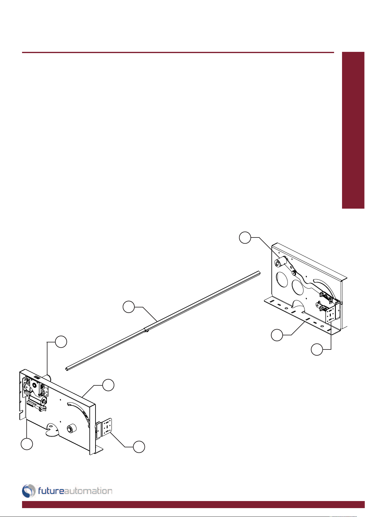
Package Contents
1 - Mechanism
1.1 - Drive Side Unit
1.2 - Slave Side Unit
1.3 - Telescopic Drive Shaft
1.4 - Locking Bosses
1.5 - Flap Mount Brackets
Not Shown On Page
2 - Multi Pack Of Nuts, Bolts & Washers
3 - Mains Power Lead
Nuts & Bolts Multipack:
A range of nuts, bolts, washers
and spacers to help aid in the
mounting for your flap
1.4
Installation: Package Contents
1.3
1.2
1.4
1.5
1.1
1
1.5
Page 4 of 12 // email info@futureautomation.co.uk tel: +44 (0) 1438 833577 fax: +44 (0) 1438 833565
Page 6
EBF - End Bed Flap
Before you start
Prior to installation check the following:
- The product is in good condition
- No damage to any parts
- Wiring is all secure
- Test the mechanism by running it
NOTE - The UBL / UBLS will
Installation: Stage 1
NOT work until the EBF is
connected to the control box
General Mechanism
Assembly
Page 5 of 12 // email info@futureautomation.co.uk tel: +44 (0) 1438 833577 fax: +44 (0) 1438 833565
Page 7
EBF - End Bed Flap
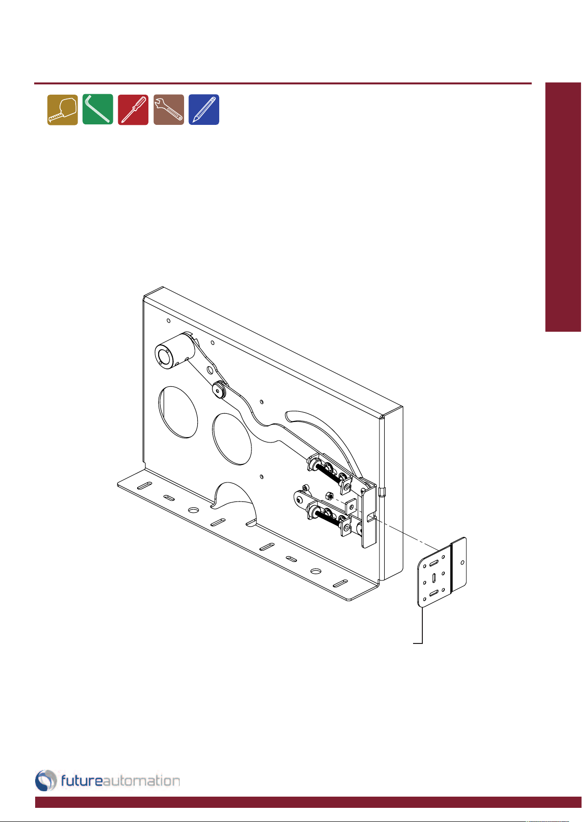
Add the flap mounting brackets
Fix the flap mounting brackets to the drive
and slave side as shown below using M6
nuts and washers.
Installation: Stage 2
Flap Mounting Bracket
Page 6 of 12 // email info@futureautomation.co.uk tel: +44 (0) 1438 833577 fax: +44 (0) 1438 833565
Page 8

EBF - End Bed Flap
Fixing the drive and slave side units down
Installation: Stage 3
Fix down to the floor
using appropriate fixings
Align the sides flush to the
internal end of the bed
Page 7 of 12 // email info@futureautomation.co.uk tel: +44 (0) 1438 833577 fax: +44 (0) 1438 833565
Page 9

EBF - End Bed Flap
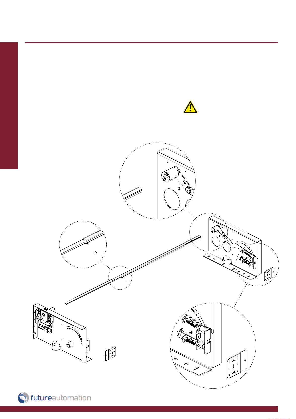
Connecting the drive shaft
To adjust the telescopic width to suit
the flap loosen the grub screw and
slide in or out to required length
Fix the drive shaft to the
side units as shown below
Installation: Stage 4
Side
Attachment
Telescopic
Adjustment
Page 8 of 12 // email info@futureautomation.co.uk tel: +44 (0) 1438 833577 fax: +44 (0) 1438 833565
Page 10

EBF - End Bed Flap
Fixing the Flap
Offer the flap into position through the bed end void and fix
through the flap mount brackets on both side.
Try to keep the gap around the flap equal all the way round
Installation: Stage 5
and the minimum gap should be 3mm [0.1”].
Fix through the flap mount brackets slots first for adjustment.
Once happy with the position use the counter sink holes.
Page 9 of 12 // email info@futureautomation.co.uk tel: +44 (0) 1438 833577 fax: +44 (0) 1438 833565
Page 11

EBF - End Bed Flap
Adjusting the flap
Use the Flap Corner Adjusters on each side
to push and pull the flap corners to level the
flap with the footboard.
Recommended clearance should be min
3mm [0.1”]
NOTE - These are the only
adjustments available. The
IN / OUT switch positions are
fixed.
Use a ball driver or a allen key to turn the
adjustment bolts as shown to the right.
Installation: Stage 6
Flap Corner Adjusters
Page 10 of 12 // email info@futureautomation.co.uk tel: +44 (0) 1438 833577 fax: +44 (0) 1438 833565
Page 12

EBF - End Bed Flap
Test and run the flap
Plug the wiring loom into the
drive side as shown
Installation: Stage 7
Test the flap and make sure it
runs correctly and nothing is in
the path of the flap
NOTE - The UBL / UBLS will
NOT work until the EBF is
connected to the control box.
The control box requires 2
mains inputs, one to power
the EBF and the other to
power the UBL / UBLS.
Page 11 of 12 // email info@futureautomation.co.uk tel: +44 (0) 1438 833577 fax: +44 (0) 1438 833565
Page 13

EBF - End Bed Flap
Adding the UBL / UBLS
Finally slide the UBL or UBLS under the bed and fix into place using the
Tech Sheet for relevant dimensions
Installation: Stage 8
Page 12 of 12 // email info@futureautomation.co.uk tel: +44 (0) 1438 833577 fax: +44 (0) 1438 833565
Page 14

Future Automation
Unit 2 Kimpton Enterprise Park
Claggy Road
Kimpton
Hertfordshire
SG4 8HP
United Kingdom
Tel: +44 (0) 1438 833 577
Fax: +44 (0) 1438 833 565
Email: info@futureautomation.co.uk
www.futureautomation.co.uk
 Loading...