

Page 1
Installation Instructions
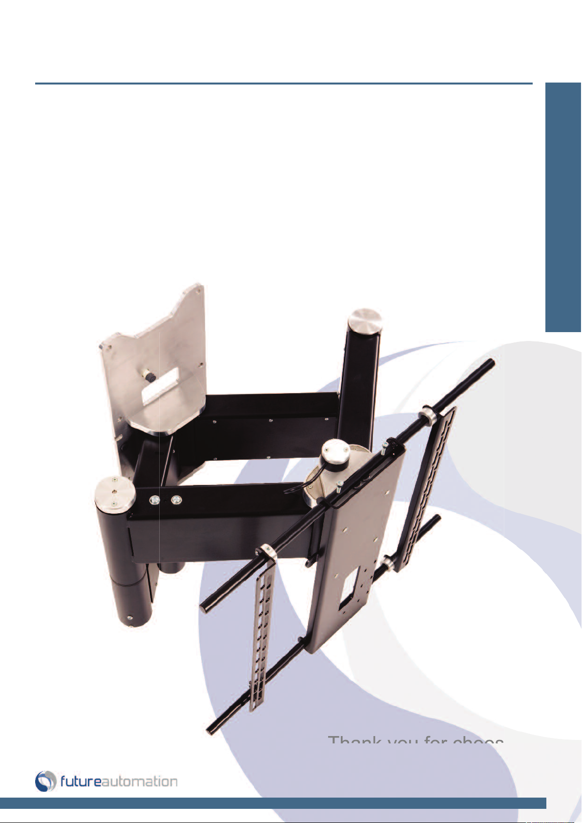
QA2 & QA2-60 - Quad Arm
Design Highlights
-Parallel Track for beautifully tight recessed finish
-Bidirectional rotating head for 150 degree rotation
-Smooth quiet motion
-Full Cable Management
-Range of preset positions
-Onboard Electronics
Wall Mounts
Thank you for choosing
futureautomation
email info@futureautomation.co.uk tel: +44 (0) 1438 833577 fax: +44 (0) 1438 833565 ISSUE 001
Page 2
QA2 & QA2-60 - Quad Arm
Safety Disclaimer
Important Safety Instructions
Explanation of graphical symbols
-(Electric Shock Symbol) = The lightning flash within an equilateral triangle is intended to alert you to the presence of un-insulated
“dangerous voltage” within the products enclosure that may be of sufficient magnitude to constitute an electric shock to persons
-(Caution Symbol) = The exclamation point within an equilateral triangle is intended to alert you to the presence of important
operating and maintenance (servicing) instructions in the literature accompanying the product
-(Tools Symbols) = The tools symbol within a coloured square are intended to highlight the required tools necessary for correct and
safe installation of the product. These are intended as a
guide only, and it is at the installer’s discretion as to which tools are used.
WARNING: RISK OF ELECTRIC SHOCK, ONLY AUTHORIZED INSTALLERS TO OPEN THE POWER CONTROL BOX.
WARNING: To reduce the risk of fire or electric shock, do not expose electrical parts to rain or moisture, unless the
product has been specifically designed to do so.
Introduction: Safety Information
WARNING: Failure to provide adequate structural strengthening, prior to installation can result in serious personal injury or damage to the
equipment. It is the installer’s responsibility to ensure the structure to which the component is affixed can support the four times the
weight of the component.
WARNING: Do not exceed the weight capacity. This can result in serious personal injury or damage to the equipment. It is the installer’s
responsibility to ensure that the total combined weight of all attached components does not exceed that of the maximum figure stated.
WARNING: Failure to provide adequate structural strength for this component can result in serious personal injury or damage to equipment! It is the installer’s responsibility to make sure the structure to which this component is attached can support five times the combined
weight of all equipment. Reinforce the structure as required before installing the component.
Warnings:
1. Read all technical instructions fully before installation and use. It is the installer’s responsibility to ensure that all
documentation is passed on the end user and read fully before operation.
2. Keep all documentation.
3. Heed all warnings.
4. Follow all technical specifications and instructions during installation.
5. Do not use near water unless the product has been specifically designed to do so.
6. Clean only with a dry cloth.
7. Do not defeat the purpose of the polarized or grounding type plug. A polarized plug has two blades, one wider
than the other. A grounding type plug has two blades and a grounding prong. The wide blade or third prong are
provided for your safety. If the provided plug does not fit your outlet, consult an electrician or contact the
manufacturer.
8. Protect the power cord from being walked on or pinched, particularly at plugs, convenience receptacles, and the
point where the exit from the apparatus.
9. Unplug the apparatus during lightning storms or when unused for long periods of time.
10. Only use attachments/accessories specified by the manufacturer.
11. Refer all servicing to qualified personnel. Servicing is required regularly on an annual basis, when the apparatus is
damaged in any way, liquid has been spilled or objects have fallen into the apparatus, the apparatus has been
exposed to rain or moisture, does not operate normally, or has been dropped.
12. To completely disconnect the apparatus form the AC mains, disconnect the power cord plug from the AC
receptacle on the power control box.
13. To prevent overheating, do not cover the apparatus. Install in accordance with the instructions.
14. UK, Ireland and Hong Kong only – The power cord is supplied with a 13A plug having an earthing pin. The
apparatus is earthed and this pin is not required for safety, merely to operate the safety shutter of mains outlet.
15. No naked flames such as lit candles should be placed on the unit.
16. Observe and follow the local regulations when disposing of batteries.
17. Do not expose the unit to dripping or splashing fluids.
18. Do not place objects filled with liquid, such as vases, on the unit.
19. Do not expose the batteries to excessive heat such as sunshine, fire or the like.
20. For all mounted apparatus, the apparatus should be installed on solid wood, bricks, concrete or solid wood
columns and battens.
21. Always turn off power at source before putting on or taking off parts and cleaning.
22. Do not use outdoors unless marked for outdoor use.
23. Exceeding the weight capacity can result in serious personal injury or damage to equipment.
Caution
Warning
Beware of
Moving Parts
Danger
Electricity
Keep Hands
Clear
Future Sound & Vision trading as Future Automation intend to make this and all documentation as accurate as possible. However, Future
Automation makes no claim that the information contained herein covers all details, conditions or variations, nor does it provide for every
possible contingency in connection with the installation or use of this product. The information contained in this document is subject to
change without prior notice or obligation of any kind. Future Automation makes no representation of warranty, expressed or implied,
regarding the information contained herein. Future Automation assumes no responsibility for accuracy, completeness or sufficiency of the
information contained in this document.
Page 1 of 22 // email info@futureautomation.co.uk tel: +44 (0) 1438 833577 fax: +44 (0) 1438 833565
Page 3

QA2 & QA2-60 - Quad Arm
Contents Page
Introduction
Safety Information 1
Contents 2
Contents 3
Tool Indicator Icons 3
Product Warranty 3
Installation
Parts List
Package Contents 4
Stage 1
Before you Start Check the Following 5
Stage 2
Screen Upright Mounting 6
Stage 3
Fitting the Mechanism to the Wall 7
Stage 4
Removing Panel Covers 8
Stage 5
Cable Management 9
Stage 6
Testing Mechanism & Replacing the Panel Covers 10
Stage 7
Mounting the Screen 11
Stage 8
Marine Lock Option 12
Stage 9
Final Checks & Set Up 13
Stage 10
Manual Head Rotation 14
Stage 11
Manual Head Rotation 15
Stage 12
Operation Buttons for the IR Remote 16
Electrical Connections
Contact Closure 17
RS232 18
Introduction: Contents
Operations
Connectivity Details 19
Changing Batteries 19
Trouble Shooting 20
Technical Overview 21
Page 2 of 22 // email info@futureautomation.co.uk tel: +44 (0) 1438 833577 fax: +44 (0) 1438 833565
Page 4
QA2 & QA2-60 - Quad Arm
Introduction: Contents / Tool Indicator
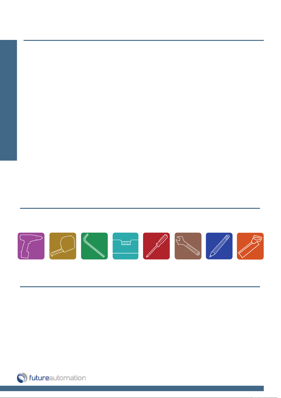
Tool Indicator Icons
1. 2. 3. 4. 5. 6.
7.
8.
1. - Drill 3. - Allen Keys 5. - Screwdrivers 7. - Pencil
2. - Tape measure 4. - Spirit Level 6. - Spanners 8. - Saw
This product carries a warranty that covers the cost of labour and spare parts incurred by any defects in materials and workmanship under normal use
during a two year period from date of purchase. Support for any problems that are not hardware faults are excluded from the warranty entitlement.
This warranty does not affect your statutory consumer rights.
The following is excluded from warranty service:
• Malfunctioning caused by misuse or damage, accidental or otherwise, or service modification by persons not authorised by Future Automation,
or the use of any non Future Automation supplied parts;
• Any electrical, or other environmental work external to your Future Automation mechanism including power cuts, surges or lightning strikes;
• Additional items not supplied by Future Automation although they may have been supplied together by the retailer;
• Any 3rd party software products controlling your mechanism;
• Any transfer of ownership. Warranty is provided only to the initial purchaser;
• Compensation for loss of use of the product, and consequential loss of any kind;
• Use of the product over the specified weight capacity;
• Any damage to products during transit that is not checked and notified as “unchecked” or “damaged” upon receipt of delivery.
Product Warranty
Any part of your system that needs to be replaced during a warranty repair becomes the property of Future Automation.
Page 3 of 22 // email info@futureautomation.co.uk tel: +44 (0) 1438 833577 fax: +44 (0) 1438 833565
Page 5
QA2 & QA2-60 - Quad Arm
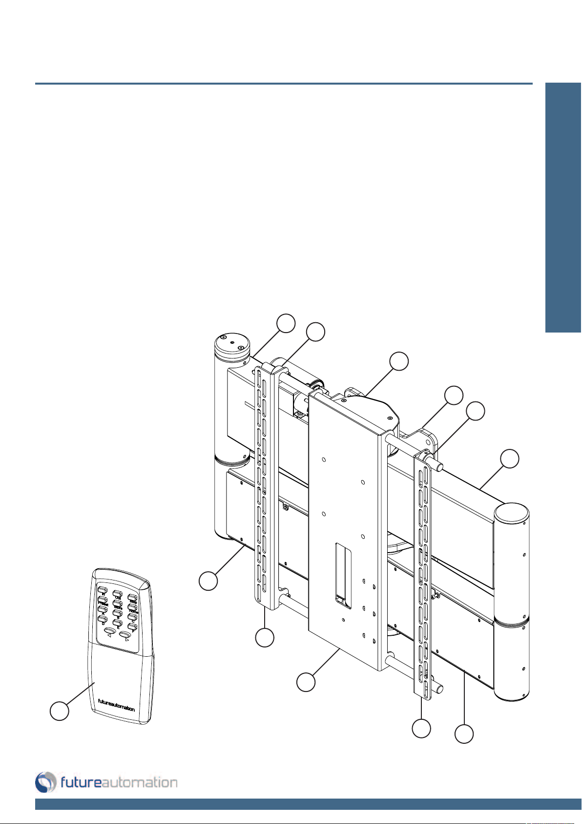
Package Contents
1 - Mechanism
1.1 - Screen Mount Plate
1.2 - Wall Mount Plate
1.3 - Screen Upright
1.4 - Screen Upright Restraint
1.5 - Arm Cover
1.6 - Upright Restraints
2 - IR Remote Control
Not Shown On Page
3 - x2 AAA Batteries
4 - Multi Pack Of Nut, Bolts & Washers
5 - Mains Power & Other Leads
Nuts & Bolts Multipack:
A range of nuts, bolts, washers
and spacers to help add in the
mounting for your screen
(Your pack may also contain a
custom adapter if your screen is
not VESA compatible)
1.4
1.6
1
Installation: Package Contents
1.5
1.2
1.6
1.4
1.3
1.1
2
1.3
Page 4 of 22 // email info@futureautomation.co.uk tel: +44 (0) 1438 833577 fax: +44 (0) 1438 833565
1.5
Page 6
QA2 & QA2-60 - Quad Arm
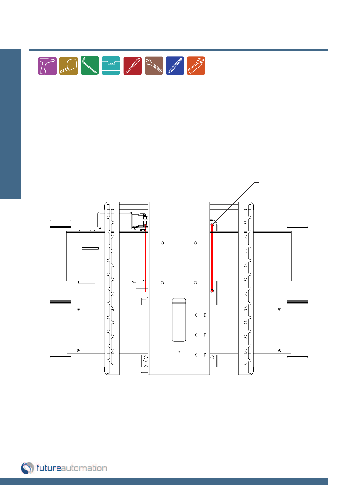
Before you Start, Check the Following:
-The product is in good condition
-No damage to any parts
-Wiring is all secure
Installation: Stage 1
-The unit is in the closed position
-Remove transit red cable ties before operating
RED TRANSIT
CABLE TIES
If your screen is not a VESA compatible, then a custom adapter will need to be added to
the QA2 bracket to suit your screen. Further instructions relating to any custom mount will
be included with the custom adapter.
When fitting the screen to the mechanism, make sure that the centre of any adaptor plate
is in line with the centre of the mechanism.
Page 5 of 22 // email info@futureautomation.co.uk tel: +44 (0) 1438 833577 fax: +44 (0) 1438 833565
Page 7
QA2 & QA2-60 - Quad Arm
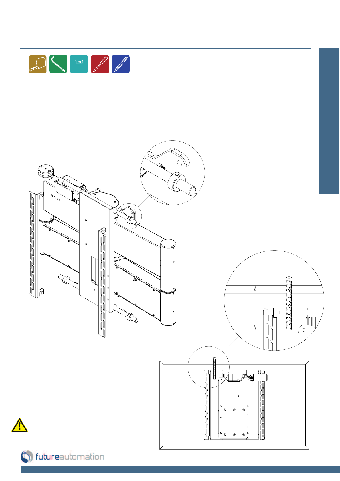
Screen Upright Mounting
First release the screen uprights by removing the bolt on the upright restraints shown
in the detail view below.
Align the uprights on the rear of the screen and measure down to the wall plate fixing
holes so mounting height can be determined on the wall.
Installation: Stage 2
Remove screen and screen
uprights before attaching the
mechanism to the wall.
Page 6 of 22 // email info@futureautomation.co.uk tel: +44 (0) 1438 833577 fax: +44 (0) 1438 833565
Page 8
QA2 & QA2-60 - Quad Arm
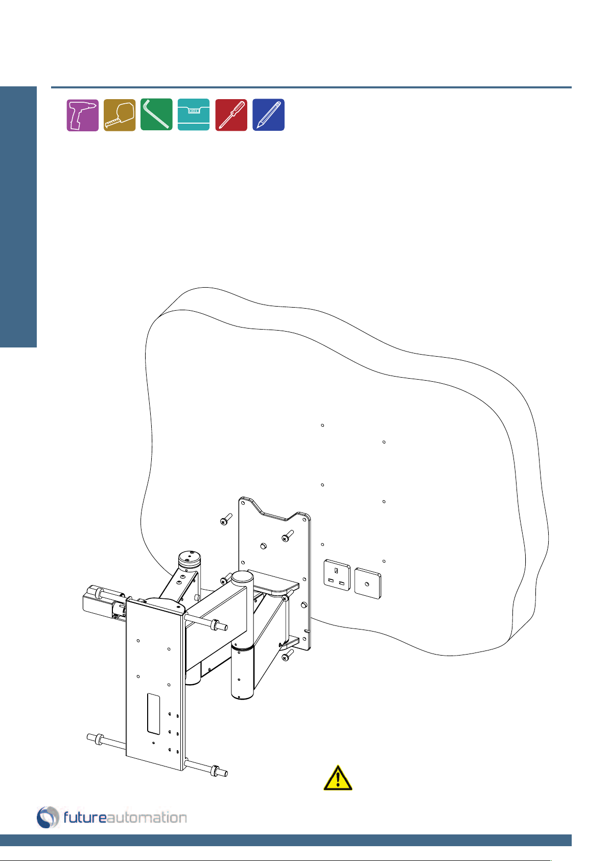
Fitting the Mechanism to the Wall
Once you have decided on the location of your screen you can fix the wall plate to the wall.
-Fix through one of the top holes first.
-Using the wall plate as a template, mark the other holes before drilling into the wall.
Installation: Stage 3
-Make sure a spirit level is used at all times to ensure mechanism is always level.
-Make sure the wall which the mechanism is being mounted to is structurally suitable.
-Minimum 2 person install step.
Page 7 of 22 // email info@futureautomation.co.uk tel: +44 (0) 1438 833577 fax: +44 (0) 1438 833565
It is the installers responsibility to
choose the appropriate fixings when
attaching to the wall and to make sure
the mechanism is secure and safe.
Page 9

QA2 & QA2-60 - Quad Arm
Removing Panel Covers
Power the mechanism half way out so all the arm cover panels are accessible.
Remove the bolts and 4 cover panels so the interiors of the arms are accessible.
Installation: Stage 4
Page 8 of 22 // email info@futureautomation.co.uk tel: +44 (0) 1438 833577 fax: +44 (0) 1438 833565
Page 10

QA2 & QA2-60 - Quad Arm
Cable Management
Feed the screen, speaker and signal cables though the bottom of the mechanism and
then out into the lower arm, then up the elbow tube and out into the upper arm. Then
out the lower face of the upper arm and through the centre of the screen plate ready to
Installation: Stage 5
connect to the screen.
Feed the mechanism power and IR cable through the other bottom arm as shown and
connect to control board.
Wall
Mechanism power
& control cables
Page 9 of 22 // email info@futureautomation.co.uk tel: +44 (0) 1438 833577 fax: +44 (0) 1438 833565
AV power and
signal cables
Page 11

QA2 & QA2-60 - Quad Arm
Testing Mechanism & Replacing Panel Covers
This is a good point to test the mechanism and make sure it’s working properly. Make sure
cables are restrained/cable tied in the arms and have enough slack for movement.
Installation: Stage 6
Finally fix all the arm panel covers back on.
Page 10 of 22 // email info@futureautomation.co.uk tel: +44 (0) 1438 833577 fax: +44 (0) 1438 833565
Page 12

QA2 & QA2-60 - Quad Arm
Mounting the Screen
Hook the screen back over the mount bars and lock in place by fixing the bolts back
through the upright restraints.
Installation: Stage 7
Screen Uprights
Upright
Restraints
Mount
Bars
Page 11 of 22 // email info@futureautomation.co.uk tel: +44 (0) 1438 833577 fax: +44 (0) 1438 833565
Page 13

QA2 & QA2-60 - Quad Arm
Marine Lock Option
An optional marine lock is available which locks the mechanism in the IN position
against the wall, making it suitable for indoor marine installations.
Installation: Stage 8
Latch
Bracket
PRODUCT CODES
QA2 M
QA2 60 M
Locking
Toggle
Page 12 of 22 // email info@futureautomation.co.uk tel: +44 (0) 1438 833577 fax: +44 (0) 1438 833565
Page 14

QA2 & QA2-60 - Quad Arm
Final Checks & Set Up
-Make sure that all side panels are fitted securely in place
-Nothing is obstructing the movement of the mechanism or screen
-Product is square and level on the wall
Installation: Stage 9
-The product condition is good and all the wiring is neatly organised
Bracket movement examples:
Page 13 of 22 // email info@futureautomation.co.uk tel: +44 (0) 1438 833577 fax: +44 (0) 1438 833565
Page 15

QA2 & QA2-60 - Quad Arm
Manual Head Rotation
To manually adjust the parallel head position remove the top head inner plate as
shown in the detail view.
Installation: Stage 10
Head Angle
Head Inner Plate
Page 14 of 22 // email info@futureautomation.co.uk tel: +44 (0) 1438 833577 fax: +44 (0) 1438 833565
Page 16

QA2 & QA2-60 - Quad Arm
Manual Head Rotation
Loosen the 4 rotational locking
bolts circled in red in the detail
view.
Installation: Stage 11
Manually rotate the head into the desired
parallel postion then lock back in place by
tighten the rotational locking bolts back up
X4 Rotational
Locking Bolts
Finally replace the head inner
plate back onto of the head
Page 15 of 22 // email info@futureautomation.co.uk tel: +44 (0) 1438 833577 fax: +44 (0) 1438 833565
Page 17

QA2 & QA2-60 - Quad Arm
Operation Buttons for the IR Remote
Installation: Stage 12
In - Brings the bracket
fully in, parallel to the wall
Out - Moves the arm out,
no head movement
< - Moves arm out, head rotates
to left viewing angle
Home - Moves the arm
out, head parallel
Store then D - Set programmable
viewing angle D
After pressing STORE you have a
2 second window to select your
save button, after 2 seconds the
command is void.
Stop - Will stop
the operation at
any position
Preset - Moves arm to recess
position, head parallel
> - Moves arm out, head rotates
to right viewing angle
Store then F - Set programmable
viewing angle F
Store then E - Set programmable
viewing angle E
Note
Only buttons indicated are functional with
the product. Any button pressed when in
motion will stop the mechanism.
OUT parallel
position
IN position
Max OUT parallel
position
Once stored limits have been set, the mechanism will not be able to travel beyond these points
Page 16 of 22 // email info@futureautomation.co.uk tel: +44 (0) 1438 833577 fax: +44 (0) 1438 833565
Max LEFT position
if limit not set
Max RIGHT position
if limit not set
Page 18

QA2 & QA2-60 - Quad Arm
SLQV
568A 568B
1 12V SUPPLY
12V SUPPLY - CURRENT LIMITED
W/G W/O
2 12V LATCH
When 12V attached, device will go OUT. When
12V removed, device will go IN.
GO
3GROUND GROUND W/OW/G
4 DEVICE LATCH
Momentary short to GROUND (pin 3), device will
go IN.
BL BL
5 VIEWING ANGLE D
Momentary short to GROUND (pin 3), moves
arm out to viewing angle D.
W/BL W/BL N / A
6 VIEWING ANGLE F
Momentary short to GROUND (pin 3), moves
arm out to viewing angle F.
O G N / A
7PRESET
Momentary short to GROUND (pin 3), moves
arm to recess position, head parallel.
W/BR W/BR N / A
8 DEVICE IN
Momentary short to GROUND (pin 3), makes
device go fully IN.
BR BR N / A
PIN
DESCRIPTION
ACTION
WIRE / CABLE
CONTACT CLOSURE
LED INDICATOR
Contact Closure
Use an RJ45 connector in the
CC1 socket on the control box
to operate via contact closure
Installation: Electrical connection
Any contact closure input whilst the
mechanism is in motion will stop the
movement and all other contact closure
commands will be disabled for 1 second.
Warning lights
- LED’s to show operation of limit
Page 17 of 22 // email info@futureautomation.co.uk tel: +44 (0) 1438 833577 fax: +44 (0) 1438 833565
switches and in switch.
Page 19

COMMAND ACTION
fa_in Device Fully IN
fa_out Moves Arm OUT, Head PARALLEL
fa_preset Moves Arm to Recess Position, Head PARALLEL
fa_left Moves Arm OUT, Rotates Head Fully LEFT
fa_right Moves Arm OUT, Rotates Head Fully RIGHT
fa_d Go to Viewing Angle D
fa_e Go to Viewing Angle E
fa_f Go to Viewing Angle F
fa_stop STOPS Device at any position
fa_save-0 Store Viewing Angle 0
fa_save-1 Store Viewing Angle 1
fa_save-2 Store Viewing Angle 2
fa_save-3 Store Viewing Angle 3
fa_save-4 Store Viewing Angle 4
fa_save-5 Store Viewing Angle 5
fa_go-0 Go to Viewing Angle 0
fa_go-1 Go to Viewing Angle 1
fa_go-2 Go to Viewing Angle 2
fa_go-3 Go to Viewing Angle 3
fa_go-4 Go to Viewing Angle 4
fa_go-5 Go to Viewing Angle 5
QA2 & QA2-60 - Quad Arm
SLQV
RS232
- Use an RJ25 connector in the socket marked
RS232 on the control box to operate using RS232
Installation: RS232
Details
RJ25 9 PIN D
Baud rate: 9600
Stop bit: 1
Parity: None
Databits: 8
PIN 1: RX TO PIN 2: TX
PIN 6: TX TO PIN 3: RX
PIN 3: GROUND TO PIN 5: GROUND
PIN 4: GROUND TO PIN 5: GROUND
IMPORTANT
Ensure protocol is entered exactly as written, including Carriage Return
(Enter / ASCII 13). After pressing STORE you have a 2 second window to
select your save button, after 2 seconds the command is void.
Page 18 of 22 // email info@futureautomation.co.uk tel: +44 (0) 1438 833577 fax: +44 (0) 1438 833565
Pin 1: RX
Pin 6 : TX
Pin 3 & 4: GROUND
Pin 2: TX
Pin 3: RX
Pin 5: GROUND
Page 20

QA2 & QA2-60 - Quad Arm
Connectivity Details
QA2
UDC3 BOARD
Installation: Operations
RS232
Contact
Closure
IR LED
EMERGENCY STOP
This connection will stop all functions of the mechanism
once broken / removed. This is where we recommend
wiring a safety device - For a range of safety devices see
control, safety & accessories section in product brochure
Mains Voltage
Input
DC2
DC1
DC3
QA2 60, QA2 M & QA2 60 M
UDC4 BOARD
DC3
RS232
Contact
Closure
IR LED
EMERGENCY STOP
This connection will stop all functions of the mechanism
once broken / removed. This is where we recommend
wiring a safety device - For a range of safety devices see
control, safety & accessories section in product brochure
Mains
Voltage
Input
DC4 DC2
DC1
Replacing Batteries
Future Automation
IR Remote
Controller needs x2
AAA batteries which
are provided within
the packaging
Page 19 of 22 // email info@futureautomation.co.uk tel: +44 (0) 1438 833577 fax: +44 (0) 1438 833565
Page 21

QA2 & QA2-60 - Quad Arm
Wall Mount QA2 - Trouble shooting
For information & technical support on our products
please refer to the relevant web site or phone number -
General Contact
info@futureautomation.co.uk
+44 (0)1438 833577
US Contact
info@futureautomation.net
+1 (603) 742 9181
Trouble Shooting:
Page 20 of 22 // email info@futureautomation.co.uk tel: +44 (0) 1438 833577 fax: +44 (0) 1438 833565
Page 22

QA2 & QA2-60 - Quad Arm
QA2 QA2 60 QA2 M QA2 60 M
Product Dimensions
(W,D,H When Closed)
777x130x520mm
[30.6x5.1x20.5"]
927x130x740mm
[36.5x5.1x29.1"]
777x130x520mm
[30.6x5.1x20.5"]
927x130x740mm
[36.5x5.1x29.1"]
Weight (Kg) 25Kg [55.1lb] 35Kg [77.2lb] 26Kg [57.3lb] 36Kg [79.4lb]
Power Consumption Max 120W Max 120W Max 120W Max 120W
Power Consumption
On Standby
3W 3W 3W 3W
Lifting Capacity (Kg) 45Kg [99.2lb] 80Kg [176.4lb] 45Kg [99.2lb] 80Kg [176.4lb]
Standard Colour Black Black Black Black
Marine In Lock No No Yes No
Max Parallel Out
Distance
750mm [29.5"] 910mm [35.8"] 750mm [29.5"] 910mm [35.8"]
Max Rotation
150ȗ
150ȗDĂdž;>ĂƌŐĞƌƐĐƌĞĞŶƐ
will have less rotation)
150ȗ
150ȗDĂdž;>ĂƌŐĞƌƐĐƌĞĞŶƐ
will have less rotation)
Min & Max Television
Size
32" - 50" 60" - 90" 32" - 50" 60" - 90"
Control
IR Remote, RF Remote,
Contact Closure & RS232
IR Remote, RF Remote,
Contact Closure & RS232
IR Remote, RF Remote,
Contact Closure & RS232
IR Remote, RF Remote,
Contact Closure & RS232
Power Supply 240V or 110V 240V or 110V 240V or 110V 240V or 110V
Control Of 3rd
Party Product
No No No No
Output Power Supply No No No No
Shipping Details
Dimensions (W,D,H)
750x200x600mm
[29.5x7.9x23.6"]
1000x200x800mm
[39.4x7.9x31.5"]
750x200x600mm
[29.5x7.9x23.6"]
1000x200x800mm
[39.4x7.9x31.5"]
Weight (Kg) 30Kg [66.1lb] 40Kg [88.2lb] 30Kg [66.1lb] 40Kg [88.2lb]
Technical Overview
A general technical overview of the QA2 two way electric wall mount.
Technical overview:
Page 21 of 22 // email info@futureautomation.co.uk tel: +44 (0) 1438 833577 fax: +44 (0) 1438 833565
Page 23

QA2 & QA2-60 - Quad Arm
Notes...
Page 22 of 22 // email info@futureautomation.co.uk tel: +44 (0) 1438 833577 fax: +44 (0) 1438 833565
Page 24

Future Automation
Unit 2 Kimpton Enterprise Park
Claggy Road
Kimpton
Hertfordshire
SG4 8HP
United Kingdom
Tel: +44 (0) 1438 833 577
Fax: +44 (0) 1438 833 565
Email: info@futureautomation.co.uk
www.futureautomation.co.uk
 Loading...